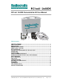
1
Radiocrafts Embedded Wireless Solutions RC1xx0 / 2x00DK RC1xx0 / 2x00DK Demonstration Kit User Manual Table of contents TABLE OF CONTENTS ............................................................................................................ 1 QUICK START GUIDE .............................................................................................................. 2 INTRODUCTION ....................................................................................................................... 3 DEMONSTRATION BOARD..................................................................................................... 4 POWER SUPPLY SECTION..................................................................................................... 5 RS-232 INTERFACE ................................................................................................................. 6 CONTROLLING CONFIG-MODE VIA THE RS232 PORT ....................................................... 6 CONNECTORS ......................................................................................................................... 7 PUSH BUTTONS ...................................................................................................................... 7 USING THE DEMONSTRATION KIT ....................................................................................... 7 ANTENNA SELECTION VERSUS RANGE PERFORMANCE ................................................ 8 CIRCUIT DIAGRAM .................................................................................................................. 9 BILL OF MATERIALS ............................................................................................................. 10 PCB LAYOUT ......................................................................................................................... 11 TROUBLESHOOTING ............................................................................................................ 13 DOCUMENT REVISION HISTORY......................................................................................... 14 DISCLAIMER .......................................................................................................................... 14 TRADEMARKS ....................................................................................................................... 14 LIFE SUPPORT POLICY ........................................................................................................ 14 CONTACT INFORMATION ..................................................................................................... 14 2008 Radiocrafts AS RC1xx0 / 2x00DK Demonstration Kit version 3.0 User Manual (rev. 3.2) Page 1 of 14 Radiocrafts Embedded Wireless Solutions RC1xx0 / 2x00DK Quick Start Guide How do I set up a simple link between the boards? To do a basic communication test, do like this for each of the Demonstration Boards: • • • • Attach the antenna to the SMA connector Connect the RS232 port to a PC Start a terminal program on the PC (like Microsoft HyperTerminal). Make sure to select the correct serial port, set data rate 19200, 1 start bit, no parity, 1 stop bit, no flow control. Connect the battery eliminator plug to the DC jack. Put the battery eliminator in the wall outlet socket. The module will now be in idle mode listening for a valid data packet to arrive. Now you can enter data in one terminal window and after approximately 2 seconds timeout, the ASCII string is transmitted to the other module and shown in the other terminal window if the transmission was successful. How do I go on and change the RF channel or any other parameter? To change configurable parameters, assert the CONFIG pin (pulling low by pressing CONFIG-button, see Figure 1), and send the command string using the same serial interface as for transmitting data. Parameters can be changed permanently and stored in non-volatile memory in the module. The details for this you should look up in the RC232 User Manual. The best way to use the configuration interface of the module is to use a terminal program that provides the possibility to send and receive binary / hexadecimal numbers, and not only ASCII characters. 2008 Radiocrafts AS RC1xx0 / 2x00DK Demonstration Kit version 3.0 User Manual (rev. 3.2) Page 2 of 14 Radiocrafts Embedded Wireless Solutions RC1xx0 / 2x00DK Introduction The RC1xx0 and RC2x00 RF modules with embedded protocol (RC232, Wireless MBUS or custom specific) provide a very compact solution for a wide range of applications. The Demonstration Kit is designed to make it easy for the user to evaluate the module and develop an application and build prototypes very quickly. The Demonstration Kit includes two Demonstration Boards. The Demonstration Boards contain the RC10xx, RC11xx, RC12xx, RC2000 or RC2100 module and associated support circuits. The board can easily be operated using a PC terminal emulator. This User Manual describes how to use the Demonstration Kit and provides detailed documentation for the Demonstration Board. The Demonstration Kit includes what you need to evaluate the RF performance of the modules, develop your own application interfacing the modules, and can also be used to build a prototype of your application. Your Demonstration Kit should contain the following items: Kit contents Item Demonstration Board (RC1xx0/RC2x00DB) Antenna, 50Ω quarter-wave monopole, SMA male connector SMA to BNC adapters RS232 serial cable (1:1) AC/DC battery eliminator 6VDC 2008 Radiocrafts AS Number of articles 2 2 2 2 2 RC1xx0 / 2x00DK Demonstration Kit version 3.0 User Manual (rev. 3.2) Page 3 of 14 Radiocrafts Embedded Wireless Solutions RC1xx0 / 2x00DK Demonstration Board The Demonstration Board contains a serial port driver circuit for RS232 and the 9-pin D-Sub connector, buttons (CONFIG, TXEN, RXEN, RESET), voltage regulator, configuration jumpers and connectors to make it easy to interface the onboard module with various test equipment or the host used in an application. Not all components are needed in an actual application. Please see the datasheet for each specific module for a typical application circuit. The Demonstration Board comes in different versions, equipped with the different variants of the modules. Among the frequencies supported are 433 MHz, 868 MHz, 915 MHz and 2.45 GHz. For each frequency there exist narrowband versions (RC12x0-series) and wideband versions (RC11x0-series and RC2x00). This covers the most used frequency bands, the 433 MHz band in Europe and the US, the 868 MHz band in Europe, the 902-928 MHz band in the US and the 2 450 MHz band world-wide. The actual module mounted can be seen on the marking on the module itself. DC jack Supply voltage terminal block RX232 D-Sub Antenna connector Digital I/O connector RESET RC1xx0 or RC2x00 RXEN TXEN CONFIG Figure 1: RC1xx0/RC2x00 Demonstration Board 2008 Radiocrafts AS RC1xx0 / 2x00DK Demonstration Kit version 3.0 User Manual (rev. 3.2) Page 4 of 14 Radiocrafts Embedded Wireless Solutions RC1xx0 / 2x00DK Power supply section The board contains a voltage regulator. You can choose between applying a 4-10V unregulated supply voltage at the DC jack (like the equipped battery eliminator), or the screw terminal where a battery pack or some other supply can be connected. The on-board regulator drops the voltage to 3.0V. Input supply voltage range is 4 – 10 V. A series diode protects the circuit against wrong polarity. An ampere meter can be connected in order to measure the DC current drawn by the module. Remove the jumper on connector P15 and connect the ampere meter between the two pins as shown in the figure below. Remove jumper and connect ampere meter at P15 to measure current consumption VDD output from module available at P9 pin 5* Short here to set module in OFF mode* Figure 2. Module current consumption measurement As shown in the figure above there are also available connection points for setting the module in OFF mode* and for VDD monitoring, both optional connections for test purposes. Note: The 100k pull-up resistor R2 will draw approximately 27 uA in OFF mode if not removed. The pull-up resistor is used to keep the module in ON mode for normal use. In a real application this pin could be controlled by a digital output, and (the pull-up) R2 could be omitted, and hence the very low OFF mode current consumption could be achieved. *VDD and ON/OFF pin is not supported by the RC11XX modules 2008 Radiocrafts AS RC1xx0 / 2x00DK Demonstration Kit version 3.0 User Manual (rev. 3.2) Page 5 of 14 Radiocrafts Embedded Wireless Solutions RC1xx0 / 2x00DK RS-232 interface The Demonstration Board provides an RS232 driver circuit. The serial port is configured as a data modem and a 1:1 cable should be used to connect the board to the PC. The RTS/CTS handshaking pair is also provided, so that hardware handshaking may be used on this port, but this is not enabled in the default configuration from the factory. Handshaking can be enabled by changing the configuration in permanent memory, see RC232 User Manual, and doing the following changes: • • Remove jumper at P14 Insert jumpers at P13 to connect CTS and RTS to the RS232 driver Move jumpers at P13 to the right for enabling CTS and RTS Remove jumper at P14 for enabling CTS Figure 3: Enabling CTS and/or RTS handshake P13 is used to set jumpers to connect the module UART interface to the RS232 PHY driver. Normally the jumpers connecting RXD and TXD are installed, and provide UART communication with a PC without handshaking. With the jumpers removed the modules RXD and TXD can easily be connected to a host, for instance a microcontroller or external development board. The table below shows the pinout and signals at P13. Pin no. 1 3 5 7 9 11 13 2 4 6 8 10 12 14 Signal GND CTS RTS CONFIG TXD RXD GND Note Install jumper when using hardware handshake Install jumper when using hardware handshake Jumper installed from factory Jumper installed from factory Note: The module CTS is set up during the first stop bit sent to the module when the buffer is full, and the host should then halt further character transmissions to prevent character loss. If the host can not detect the CTS quickly enough during hardware handshake, it should be configured for two stop bits. Controlling CONFIG-mode via the RS232 port The module can enter CONFIG-mode by toggling the RTS-signal from the host (microcontroller or PC). By doing so, the Demonstration Board can act as a modem without the need for manually or with other circuitry asserting the CONFIG-pin. Modification procedure: On the bottom side of the PCB (layer 2), solder a connection between Pin 7 and Pin 8 on P13 as seen in Figure 4, right picture, if required (the pins might already be connected on newest PCB revisions). Then place the jumpers as shown in Figure 4, left picture. Config-mode is now enabled when RTS signal is asserted low. RTS can normally be controlled via various terminal-programs. 2008 Radiocrafts AS RC1xx0 / 2x00DK Demonstration Kit version 3.0 User Manual (rev. 3.2) Page 6 of 14 Radiocrafts Embedded Wireless Solutions RC1xx0 / 2x00DK Figure 4. Jumper placement and solder connection for connecting RTS to CONFIG Connectors The Demonstration Board is furnished with many connectors for easy access to all module signals. P5 (and P13) bring out all the digital data and control lines used to interface the module. P9 brings out supply voltage and ON/OFF signals (Not supported for RC11XX). A 2.54 mm pitch pin-row can be mounted at P9 if convenient. P6 brings out digital I/O for future use and custom specific applications, and analogue RSSI (if applicable for the module variant). A 2.54 mm pitch pin-row can be mounted at P6 if convenient. P7 brings out digital I/O for future use. A 2.54 mm pitch pin-row can be mounted at P7 if convenient. P8, P10 and P11 are for factory test only and not equipped on the PCB. Push buttons The Demonstration Board is furnished with four push buttons connected to the control signals: S1: RXEN. Pressing this button will activate RX when using un-buffered mode. S2: TXEN. Pressing this button will activate TX when using un-buffered mode. S3: CONFIG. Pressing this button will activate configuration mode. S4: RESET. Pressing this button will activate the main RESET of the module. Using the Demonstration Kit The Demonstration Kit is useful for providing hands-on experience with the RC1xx0/RC2x00 for both software and hardware developers. Follow the Quick Start Guide instructions to hook up the kit. The RC232 User Manual together with the Data Sheet for each specific module provides information on how to change the configurations of the modules. Important: The use of radio transceivers is regulated by international and national rules. Radiocrafts’ modules meet the regulations in EU and US/Canada for different frequency variants. Make sure the local regulative are according to these rules. Your local telecommunication authorities can provide more information on use of un-licensed radio transmitter in your country. 2008 Radiocrafts AS RC1xx0 / 2x00DK Demonstration Kit version 3.0 User Manual (rev. 3.2) Page 7 of 14 Radiocrafts Embedded Wireless Solutions RC1xx0 / 2x00DK Antenna Selection versus range performance The choice of antenna is crucial for achieving the maximum range for any radio system. Due to the small size of the PCB and the off-centre placement of the onboard SMA connector the Demo Boards will not demonstrate the maximum range or omni directional radiation. To improve this, a larger groundplane and a centred placement of the antenna above this groundplane is required. One possible solution for maximum radiation is shown in the figure below. With the addition of two different SMA adaptors and one sufficiently large groundplane (radius ≥ L, length of the antenna) and a good electrical connection to the GND-layer, an optimum performance of the antenna following the kit is achieved. Other antenna solutions can be tested by connecting to the excisting SMA female connector on the Demo Board via one of the methods below: 1. Solder the feeding point of the antenna to be tested directly to an SMA male connector and fasten to the SMA female connector 2. Connect to an external antenna (or board with antenna) via a shortest possible 50 Ohm coax cable with minimum insertion loss Antenna Antenna length L Minimum radius of GND plane = L PCB with solid bottom GND layer SMA female/female adaptor in drilled hole SMA male/male adaptor Radiocrafts Demo Board Proper connection betwen GND plane and adaptor outer shielding Figure 5: Extending size of ground plane with extra PCB 2008 Radiocrafts AS RC1xx0 / 2x00DK Demonstration Kit version 3.0 User Manual (rev. 3.2) Page 8 of 14 Radiocrafts Embedded Wireless Solutions RC1xx0 / 2x00DK Circuit Diagram The circuit diagram is shown below. A full resolution schematic is found in RC1xx0DB_3_0.zip available from Radiocrafts’ webpage. Note: For the RC11XX modules the following changes apply: - Reset button is strapped to pin 6 and disconnected from pin 22 - U3 removed 2008 Radiocrafts AS RC1xx0 / 2x00DK Demonstration Kit version 3.0 User Manual (rev. 3.2) Page 9 of 14 Radiocrafts Embedded Wireless Solutions Reference C1 C2 C3-7 D1 D2 M1 P1 P2 P3 P4 P13 R1 R2;R7-9 R3 S1-4 U1 U2 U3 RC1xx0 / 2x00DK Bill of materials Quantity 1 1 5 1 1 1 1 1 1 1 1 1 4 1 4 1 1 1 2008 Radiocrafts AS Part number C_2U2_0603_X5R_K_10 C_3U3_TAN_B C_100N_0603_X7R_K_50 BAT254 LED_CL150GCD RC1XX0 DSUB_9F SCREW_TERM_2 DC_JACK_2.5 SMA CON_2X7_TH_MALE R_0_0603 R_100K_0603_G R_150_0603_G PUSH_BUTTON MAX3232 LP2980-3.0V TPS3809J25 Description Capacitor, 0603 Capacitor, tantal Capacitor, 0603 Diode, Si Green LED RF Module D-Sub, 9 pin, female 2 pin terminal, screw DC jack, 2.5mm center pin SMA connector, straight Connector 14 pins, pin header Resistor, 0603 Resistor, 0603 Resistor, 0603 Push button, SMD RS-232 Transceiver, SO-16 3.0V low drop-out regulator Voltage supervisor, 2.5V, SOT-23 RC1xx0 / 2x00DK Demonstration Kit version 3.0 User Manual (rev. 3.2) Page 10 of 14 Radiocrafts Embedded Wireless Solutions RC1xx0 / 2x00DK PCB layout The PCB is a simple 2-layer board where the bottom layer is used as ground plane. The laminate used is standard FR-4 board material. The PCB is 1.6mm thick. Full resolution layout and assembly drawing are found in RC1xx0DB_3_0.zip. Figure 6: RC1xx0/2x00DB PCB layout, top layer (1) Figure 7: RC1xx0/2x00DB PCB layout, bottom layer (2) 2008 Radiocrafts AS RC1xx0 / 2x00DK Demonstration Kit version 3.0 User Manual (rev. 3.2) Page 11 of 14 Radiocrafts Embedded Wireless Solutions RC1xx0 / 2x00DK Figure 8: RC1xx0/2x00DB PCB component placement, top side 2008 Radiocrafts AS RC1xx0 / 2x00DK Demonstration Kit version 3.0 User Manual (rev. 3.2) Page 12 of 14 Radiocrafts Embedded Wireless Solutions RC1xx0 / 2x00DK Troubleshooting It doesn’t work • Is the battery eliminator plugged into the wall socket? • Do you have the correct power source? If you use an AC/DC battery eliminator check also that it has the correct AC-voltage rating for your outlet (220V or 110V). • Measure the supply voltage at P15. Should be 3.0V and a strap or ampere meter must connect the two pins. • First, measure the supply voltage at P9, pin 3. Should be 3.0V. • Is the supply voltage correctly polarized? If not, the protection diode will prevent any current from flowing. + and – are indicated on the PCB, on the DC jack, the tip is + and the ring is –. I cannot communicate with the RC1XX0 UART through the serial port • Make sure that the RXD and TXD jumpers are inserted. • Set up your terminal program according to the instructions in the Quick Start Guide. Remember to select the correct COM-port and connect to this port. • Make sure that you are using a correctly wired 1:1 cable (as the one provided with the kit). • Entering configuration mode (by press CONFIG button) the command prompt (“>”) should be displayed on the terminal window. Make sure to exit the command mode using the exit command (capital “X”). I cannot communicate between two modules in buffered mode • Make sure that the address mode and CRC mode is the same in both modules (set using the “M” Memory configuration command, refer to the RC232 User Manual). • Make sure the destination address is the same as the other modules Unique ID if addressing is used (set using the “T” Destination address command, refer to the RC232 User Manual). • Make sure to exit from command mode using capital “X”. • The present configuration can be listed to the terminal using the test command “0” (zero). The module consumes more than the rated current in OFF mode • Note that the ON/OFF signal pull up resistor R2 (100 kΩ) draws approximately 27 uA. Remove this resistor when measuring the module current in OFF mode. I cannot access configuration mode when I press the CONFIG button • Press and hold CONFIG button while pushing the RESET button (or power up the board). The reason you could not enter configuration mode, is most likely that some configuration memory values have been set to illegal values. List and check all values using the ‘0’ (zero) command. Set all values back to default values (see RC232 User Manual or the respective Data Sheet). • Note: If the mode is already in configuration mode it will not respond with another prompt if the CONFIG button is pressed. Send the ‘0’ (zero) command to the module in order to check if it is already in configuration mode. 2008 Radiocrafts AS RC1xx0 / 2x00DK Demonstration Kit version 3.0 User Manual (rev. 3.2) Page 13 of 14 Radiocrafts Embedded Wireless Solutions Document Revision History Document Revision 1.0 2.0 3.0 3.1 RC1xx0 / 2x00DK Changes First release Minor updates. This revision applies for Demo Board revision 2.0 Updated according to Demo Board revision 3.0 Added chapter “Control CONFIG-mode via the RS232 port”. Added figure 4 and corrected text under figure 3. RC11XX information added 3.2 Disclaimer Radiocrafts AS believes the information contained herein is correct and accurate at the time of this printing. However, Radiocrafts AS reserves the right to make changes to this product without notice. Radiocrafts AS does not assume any responsibility for the use of the described product; neither does it convey any license under its patent rights, or the rights of others. The latest updates are available at the Radiocrafts website or by contacting Radiocrafts directly. As far as possible, major changes of product specifications and functionality, will be stated in product specific Errata Notes published at the Radiocrafts website. Customers are encouraged to check regularly for the most recent updates on products and support tools. Trademarks RC232™ is a trademark of Radiocrafts AS. The RC232™ Embedded RF Protocol is used in a range of products from Radiocrafts. The protocol handles host communication, data buffering, error check, addressing and broadcasting. It supports point-to-point, point-to-multipoint and peer-to-peer network topologies. All other trademarks, registered trademarks and product names are the sole property of their respective owners. Life Support Policy This Radiocrafts product is not designed for use in life support appliances, devices, or other systems where malfunction can reasonably be expected to result in significant personal injury to the user, or as a critical component in any life support device or system whose failure to perform can be reasonably expected to cause the failure of the life support device or system, or to affect its safety or effectiveness. Radiocrafts AS customers using or selling these products for use in such applications do so at their own risk and agree to fully indemnify Radiocrafts AS for any damages resulting from any improper use or sale. © 2008, Radiocrafts AS. All rights reserved. Contact Information Web site: www.radiocrafts.com Address: Radiocrafts AS Sandakerveien 64 NO-0484 OSLO NORWAY Tel: +47 4000 5195 Fax: +47 22 71 29 15 E-mails: [email protected] [email protected] [email protected] 2008 Radiocrafts AS RC1xx0 / 2x00DK Demonstration Kit version 3.0 User Manual (rev. 3.2) Page 14 of 14