1
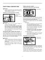
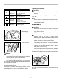
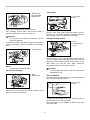
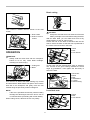
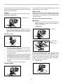
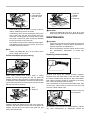
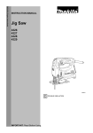
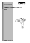
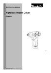
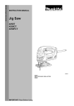
ENGLISH (Original instructions)
INSTRUCTION MANUAL
Cordless Jig Saw
DJV140
DJV180
007481
IMPORTANT: Read Before Using.
1
ENGLISH (Original instructions)
SPECIFICATIONS
Model
DJV140
Length of stroke
26 mm
26 mm
135 mm
135 mm
Wood
Max. cutting capacities
DJV180
Mild steel
10 mm
10 mm
Aluminum
20 mm
20 mm
Strokes per minute (min-1)
0 - 2,600
0 - 2,600
Overall length
255 mm
257 mm
Net weight
2.8 kg
2.9 kg
Rated voltage
D.C. 14.4 V
D.C. 18 V
• Due to our continuing program of research and development, the specifications herein are subject to change without notice.
• Specifications and battery cartridge may differ from country to country.
• Weight, with battery cartridge, according to EPTA-Procedure 01/2003
END004-6
Symbols
Model DJV180
The following show the symbols used for the equipment.
Be sure that you understand their meaning before use.
・ Read instruction manual.
Sound pressure level (LpA) : 84 dB (A)
Sound power level (LWA) : 95 dB (A)
Uncertainty (K) : 3 dB (A)
Cd
Ni-MH
Li-ion
・
Wear ear protection
Only for EU countries
Do not dispose of electric equipment or
battery pack together with household
waste material!
In observance of the European
Directives, on Waste Electric and
Electronic Equipment and Batteries and
Accumulators and Waste Batteries and
Accumulators and their implementation
in accordance with national laws,
electric equipment and batteries and
battery pack(s) that have reached the
end of their life must be collected
separately and returned to an
environmentally compatible recycling
facility.
ENG900-1
Vibration
The vibration total value (tri-axial vector sum) determined
according to EN60745:
Work mode : cutting boards
Vibration emission (ah,B) : 7.0 m/s2
Uncertainty (K) : 1.5 m/s2
Work mode : cutting sheet metal
Vibration emission (ah,M) : 3.5 m/s2
Uncertainty (K) : 1.5 m/s2
ENG901-1
•
ENE019-1
Intended use
The tool is intended for the sawing of wood, plastic and
metal materials. As a result of the extensive accessory
and saw blade program, the tool can be used for many
purposes and is very well suited for curved or circular
cuts.
•
•
ENG905-1
Noise
The typical A-weighted noise level determined according
to EN60745:
•
Model DJV140
Sound pressure level (LpA) : 83 dB (A)
Sound power level (LWA) : 94 dB (A)
Uncertainty (K) : 3 dB (A)
2
The declared vibration emission value has been
measured in accordance with the standard test
method and may be used for comparing one tool
with another.
The declared vibration emission value may also be
used in a preliminary assessment of exposure.
WARNING:
The vibration emission during actual use of the power
tool can differ from the declared emission value
depending on the ways in which the tool is used.
Be sure to identify safety measures to protect the
operator that are based on an estimation of
exposure in the actual conditions of use (taking
account of all parts of the operating cycle such as
the times when the tool is switched off and when it
is running idle in addition to the trigger time).
ENH101-17
5.
Avoid body contact with earthed or grounded
surfaces such as pipes, radiators, ranges and
refrigerators. There is an increased risk of
electric shock if your body is earthed or grounded.
6.
Do not expose power tools to rain or wet
conditions. Water entering a power tool will
increase the risk of electric shock.
7.
Do not abuse the cord. Never use the cord for
carrying, pulling or unplugging the power tool.
Keep cord away from heat, oil, sharp edges or
moving parts. Damaged or entangled cords
increase the risk of electric shock.
8.
When operating a power tool outdoors, use an
extension cord suitable for outdoor use. Use of
a cord suitable for outdoor use reduces the risk of
electric shock.
9.
If operating a power tool in a damp location is
unavoidable, use a ground fault circuit
interrupter (GFCI) protected supply. Use of an
GFCI reduces the risk of electric shock.
Personal safety
10. Stay alert, watch what you are doing and use
common sense when operating a power tool. Do
not use a power tool while you are tired or under
the influence of drugs, alcohol or medication. A
moment of inattention while operating power tools
may result in serious personal injury.
11. Use personal protective equipment. Always
wear eye protection. Protective equipment such
as dust mask, non-skid safety shoes, hard hat, or
hearing protection used for appropriate conditions
will reduce personal injuries.
12. Prevent unintentional starting. Ensure the
switch is in the off-position before connecting
to power source and/or battery pack, picking
up or carrying the tool. Carrying power tools with
your finger on the switch or energising power tools
that have the switch on invites accidents.
13. Remove any adjusting key or wrench before
turning the power tool on. A wrench or a key left
attached to a rotating part of the power tool may
result in personal injury.
14. Do not overreach. Keep proper footing and
balance at all times. This enables better control
of the power tool in unexpected situations.
15. Dress properly. Do not wear loose clothing or
jewellery. Keep your hair, clothing, and gloves
away from moving parts. Loose clothes, jewellery
or long hair can be caught in moving parts.
16. If devices are provided for the connection of
dust extraction and collection facilities,
ensure these are connected and properly used.
Use of dust collection can reduce dust-related
hazards.
For European countries only
EC Declaration of Conformity
Makita declares that the following Machine(s):
Designation of Machine:
Cordless Jig Saw
Model No./ Type: DJV140, DJV180
Conforms to the following European Directives:
2006/42/EC
They are manufactured in accordance with the following
standard or standardized documents:
EN60745
The Technical file in accordance with 2006/42/EC is
available from:
Makita, Jan-Baptist Vinkstraat 2, 3070, Belgium
31.12.2013
000331
Yasushi Fukaya
Director
Makita, Jan-Baptist Vinkstraat 2, 3070, Belgium
GEA006-2
General Power Tool Safety
Warnings
WARNING Read all safety warnings and all
instructions. Failure to follow the warnings and instructions
may result in electric shock, fire and/or serious injury.
Save all warnings and
instructions for future reference.
The term "power tool" in the warnings refers to your
mains-operated (corded) power tool or battery-operated
(cordless) power tool.
Work area safety
1.
Keep work area clean and well lit. Cluttered or
dark areas invite accidents.
2.
Do not operate power tools in explosive
atmospheres, such as in the presence of
flammable liquids, gases or dust. Power tools
create sparks which may ignite the dust or fumes.
3.
Keep children and bystanders away while
operating a power tool. Distractions can cause
you to lose control.
Electrical safety
4.
Power tool plugs must match the outlet. Never
modify the plug in any way. Do not use any
adapter plugs with earthed (grounded) power
tools. Unmodified plugs and matching outlets will
reduce risk of electric shock.
3
Service
28. Have your power tool serviced by a qualified
repair person using only identical replacement
parts. This will ensure that the safety of the power
tool is maintained.
29. Follow instruction for lubricating and
changing accessories.
30. Keep handles dry, clean and free from oil and
grease.
Power tool use and care
17. Do not force the power tool. Use the correct
power tool for your application. The correct
power tool will do the job better and safer at the
rate for which it was designed.
18. Do not use the power tool if the switch does
not turn it on and off. Any power tool that cannot
be controlled with the switch is dangerous and
must be repaired.
19. Disconnect the plug from the power source
and/or the battery pack from the power tool
before making any adjustments, changing
accessories, or storing power tools. Such
preventive safety measures reduce the risk of
starting the power tool accidentally.
20. Store idle power tools out of the reach of
children and do not allow persons unfamiliar
with the power tool or these instructions to
operate the power tool. Power tools are
dangerous in the hands of untrained users.
21. Maintain power tools. Check for misalignment
or binding of moving parts, breakage of parts
and any other condition that may affect the
power tool’s operation. If damaged, have the
power tool repaired before use. Many accidents
are caused by poorly maintained power tools.
22. Keep cutting tools sharp and clean. Properly
maintained cutting tools with sharp cutting edges
are less likely to bind and are easier to control.
23. Use the power tool, accessories and tool bits
etc. in accordance with these instructions,
taking into account the working conditions
and the work to be performed. Use of the power
tool for operations different from those intended
could result in a hazardous situation.
Battery tool use and care
24. Recharge only with the charger specified by
the manufacturer. A charger that is suitable for
one type of battery pack may create a risk of fire
when used with another battery pack.
25. Use power tools only with specifically
designated battery packs. Use of any other
battery packs may create a risk of injury and fire.
26. When battery pack is not in use, keep it away
from other metal objects, like paper clips,
coins, keys, nails, screws or other small metal
objects, that can make a connection from one
terminal to another. Shorting the battery
terminals together may cause burns or a fire.
27. Under abusive conditions, liquid may be
ejected from the battery; avoid contact. If
contact accidentally occurs, flush with water.
If liquid contacts eyes, additionally seek
medical help. Liquid ejected from the battery may
cause irritation or burns.
GEB045-2
CORDLESS JIG SAW SAFETY
WARNINGS
1.
2.
3.
4.
5.
6.
7.
8.
9.
10.
11.
12.
13.
14.
15.
Hold power tool by insulated gripping surfaces,
when performing an operation where the cutting
accessory may contact hidden wiring. Cutting
accessory contacting a "live" wire may make exposed
metal parts of the power tool "live" and could give the
operator an electric shock.
Use clamps or another practical way to secure
and support the workpiece to a stable platform.
Holding the work by hand or against your body
leaves it unstable and may lead to loss of control.
Always use safety glasses or goggles.
Ordinary eye or sun glasses are NOT safety
glasses.
Avoid cutting nails. Inspect workpiece for any
nails and remove them before operation.
Do not cut oversize workpiece.
Check for the proper clearance beyond the
workpiece before cutting so that the blade will
not strike the floor, workbench, etc.
Hold the tool firmly.
Make sure the blade is not contacting the
workpiece before the switch is turned on.
Keep hands away from moving parts.
Do not leave the tool running. Operate the tool
only when hand-held.
Always switch off and wait for the blade to
come to a complete stop before removing the
blade from the workpiece.
Do not touch the blade or the workpiece
immediately after operation; they may be
extremely hot and could burn your skin.
Do not operate the tool at no-load
unnecessarily.
Some material contains chemicals which may
be toxic. Take caution to prevent dust
inhalation and skin contact. Follow material
supplier safety data.
Always use the correct dust mask/respirator for
the material and application you are working with.
SAVE THESE INSTRUCTIONS.
4
WARNING:
Tips for maintaining maximum battery life
DO NOT let comfort or familiarity with product
(gained from repeated use) replace strict adherence
to safety rules for the subject product. MISUSE or
failure to follow the safety rules stated in this
instruction manual may cause serious personal
injury.
1.
2.
ENC007-8
IMPORTANT SAFETY
INSTRUCTIONS
3.
FOR BATTERY CARTRIDGE
4.
1.
Before using battery cartridge, read all
instructions and cautionary markings on (1)
battery charger, (2) battery, and (3) product
using battery.
2.
Do not disassemble battery cartridge.
3.
If operating time has become excessively
shorter, stop operating immediately. It may
result in a risk of overheating, possible burns
and even an explosion.
4.
If electrolyte gets into your eyes, rinse them
out with clear water and seek medical
attention right away. It may result in loss of
your eyesight.
5.
Do not short the battery cartridge:
(1) Do not touch the terminals with any
conductive material.
(2) Avoid storing battery cartridge in a
container with other metal objects such as
nails, coins, etc.
(3) Do not expose battery cartridge to water
or rain.
A battery short can cause a large current flow,
overheating, possible burns and even a
breakdown.
6.
Do not store the tool and battery cartridge in
locations where the temperature may reach or
exceed 50 ゚ C (122 ゚ F).
7.
Do not incinerate the battery cartridge even if
it is severely damaged or is completely worn
out. The battery cartridge can explode in a fire.
8.
Be careful not to drop or strike battery.
9.
Do not use a damaged battery.
10. Follow your local regulations relating to
disposal of battery.
SAVE THESE INSTRUCTIONS.
5
Charge
the
battery
cartridge
before
completely discharged.
Always stop tool operation and charge the
battery cartridge when you notice less tool
power.
Never recharge a fully charged battery
cartridge.
Overcharging shortens the battery service life.
Charge the battery cartridge with room
temperature at 10 ゚ C - 40 ゚ C (50 ゚ F - 104 ゚ F).
Let a hot battery cartridge cool down before
charging it.
Charge the battery cartridge once in every six
months if you do not use it for a long period of
time.
Battery protection system
(Lithium-ion battery with star marking)
FUNCTIONAL DESCRIPTION
•
CAUTION:
Always be sure that the tool is switched off and the
battery cartridge is removed before adjusting or
checking function on the tool.
1. Star marking
1
Installing or removing battery cartridge
1
1. Red indicator
2. Button
3. Battery cartridge
2
012128
Lithium-ion batteries with a star marking are equipped
with a protection system. This system automatically cuts
off power to the tool to extend battery life.
The tool will automatically stop during operation if the tool
and/or battery are placed under one of the following
conditions:
•
Overloaded:
The tool is operated in a manner that causes
it to draw an abnormally high current.
In this situation, release the switch trigger on
the tool and stop the application that caused
the tool to become overloaded. Then pull the
switch trigger again to restart.
If the tool does not start, the battery is
overheated. In this situation, let the battery
cool before pulling the switch trigger again.
•
Low battery voltage:
The remaining battery capacity is too low and
the tool will not operate. In this situation,
remove and recharge the battery.
3
007482
CAUTION:
Always switch off the tool before installing or
removing of the battery cartridge.
•
Hold the tool and the battery cartridge firmly
when installing or removing battery cartridge.
Failure to hold the tool and the battery cartridge
firmly may cause them to slip off your hands and
result in damage to the tool and battery cartridge
and a personal injury.
To remove the battery cartridge, slide it from the tool
while sliding the button on the front of the cartridge.
To install the battery cartridge, align the tongue on the
battery cartridge with the groove in the housing and slip it
into place. Insert it all the way until it locks in place with a
little click. If you can see the red indicator on the upper
side of the button, it is not locked completely.
•
•
•
Selecting the cutting action
1. Cutting action
changing lever
CAUTION:
Always install the battery cartridge fully until the red
indicator cannot be seen. If not, it may accidentally
fall out of the tool, causing injury to you or someone
around you.
Do not install the battery cartridge forcibly. If the
cartridge does not slide in easily, it is not being
inserted correctly.
1
007483
This tool can be operated with an orbital or a straight line
(up and down) cutting action. The orbital cutting action
thrusts the blade forward on the cutting stroke and
greatly increases cutting speed.
To change the cutting action, just turn the cutting action
changing lever to the desired cutting action position.
Refer to the table to select the appropriate cutting action.
6
Lighting up the lamps
Position
Cutting action
Applications
0
Straight line
cutting action
For cutting mild steel,
stainless steel and plastics.
For clean cuts in wood
and plywood.
Small orbit
cutting action
For cutting mild steel,
aluminum and hard wood.
Medium orbit
cutting action
For cutting wood and
plywood.
For fast cutting in
aluminum and mild steel.
NOTE:
•
Use a dry cloth to wipe the dirt off the lens of lamp.
Be careful not to scratch the lens of lamp, or it may
lower the illumination.
Large orbit
cutting action
For fast cutting in
wood and plywood.
ASSEMBLY
CAUTION:
Do not look in the light or see the source of light
directly.
To turn on the lamp, pull the trigger. Release the trigger to
turn it off.
•
006376
Switch action
•
2
1
1. Lock-off button
2. Switch trigger
CAUTION:
Always be sure that the tool is switched off and the
battery cartridge is removed before carrying out
any work on the tool.
Installing or removing saw blade
CAUTION:
Always clean out all chips or foreign matter
adhering to the blade and/or blade holder. Failure
to do so may cause insufficient tightening of the
blade, resulting in a serious personal injury.
•
Do not touch the blade or the workpiece
immediately after operation; they may be extremely
hot and could burn your skin.
•
Tighten the saw blade securely. Failure to do so
may cause a serious injury.
•
When you remove the saw blade, be careful not to
hurt your fingers with the top of the blade or the tips
of workpiece.
To install the blade, open the tool opener to the position
shown in the figure.
•
007484
1. Lock-off button
1
B
A
007485
CAUTION:
Before inserting the battery cartridge into the tool, always
check to see that the switch trigger actuates properly and
returns to the "OFF" position when released.
•
When not operating the tool, depress the lock-off button
from A side to lock the switch trigger in the OFF position.
To prevent the switch trigger from accidentally pulled, the
lock-off button is provided.
To start the tool, depress the lock-off button from B side
and pull the switch trigger.
Tool speed is increased by increasing pressure on the
switch trigger. Release the switch trigger to stop. After
use, always press in the lock-off button from A side.
1. Tool opener
•
1
001909
Keeping that situation, insert the saw blade into the blade
clamp as far as the two protrusions of the blade can not
be seen.
7
1
Cover plate
1. Blade clamp
2. Jig saw blade
3. Protrusions
3
1
1. Cover plate
2. Base
2
2
001910
Return the tool opener to its original position.
After installing, always make sure that the blade is
securely held in place by trying to pull it out.
007503
Use the cover plate when cutting decorative veneers,
plastics, etc. It protects sensitive or delicate surfaces
from damage. Fit it on the back of the tool base.
CAUTION:
Do not open the tool opener excessively, or it may
cause tool damage.
To remove the blade, open the tool opener to the position
shown in the figure. Pull the saw blade out toward the
base.
Anti-splintering device
•
1. Base
2. Anti-splintering
device
1. Jig saw blade
1
2
007504
For splinter-free cuts, the anti-splintering device can be
used. To install the anti-splintering device, move the tool
base all the way forward and fit it from the back of tool
base. When you use the cover plate, install the
anti-splintering device onto the cover plate.
1
001911
NOTE:
•
Occasionally lubricate the roller.
Hex wrench storage
•
1. Base
2. Hex wrench
CAUTION:
The anti-splintering device cannot be used when
making bevel cuts.
Dust extraction
The dust nozzle (optional accessory) is recommended to
perform clean cutting operations.
1
1. Dust nozzle
2. Base
1
2
007486
When not in use, store the hex wrench as shown in the
figure to keep it from being lost.
2
001921
To attach the dust nozzle on the tool, insert the hook of
dust nozzle into the hole in the base.
The dust nozzle can be installed on either left or right
side of the base.
8
Bevel cutting
001922
Then connect a Makita vacuum cleaner to the dust
nozzle.
007488
CAUTION:
Always be sure that the tool is switched off and the
battery cartridge is removed before tilting the base.
With the base tilted, you can make bevel cuts at any
angle between 0° and 45° (left or right).
Loosen the bolt on the back of the base with the hex
wrench. Move the base so that the bolt is positioned in
the center of the bevel slot in the base.
1. Dust nozzle
2. Hose for vacuum
cleaner
•
2
1
2
1
007495
1. Base
2. Bolt
3. Hex wrench
3
OPERATION
•
CAUTION:
Always hold the base flush with the workpiece.
Failure to do so may cause blade breakage,
resulting in a serious injury.
007489
Tilt the base until the desired bevel angle is obtained.
The V-notch of the gear housing indicates the bevel
angle by graduations. Then tighten the bolt firmly to
secure the base.
1. Cutting line
2. Base
1
6
2
5
007487
1
Turn the tool on without the blade making any contact
and wait until the blade attains full speed. Then rest the
base flat on the workpiece and gently move the tool
forward along the previously marked cutting line.
4
3
1. Bevel slot
2. Base
3. Bolt
4. Graduations
5. V-notch
6. Gear housing
2
007490
NOTE:
•
If the tool is operated continuously until the battery
cartridge has discharged, allow the tool to rest for
15 minutes before proceeding with a fresh battery.
When cutting curves, advance the tool very slowly.
Front flush cuts
1
007491
9
2
3
1. Base
2. Bolt
3. Hex wrench
Loosen the bolt on the back of the base with the hex
wrench and slide the base all the way back. Then tighten
the bolt to secure the base.
To trim edges or make dimensional adjustments, run the
blade lightly along the cut edges.
Cutouts
Always use a suitable coolant (cutting oil) when cutting
metal. Failure to do so will cause significant blade wear.
The underside of the workpiece can be greased instead
of using a coolant.
Metal cutting
Cutouts can be made with either of two methods A or B.
A) Boring a starting hole:
1. Starting hole
Rip fence set (optional accessory)
CAUTION:
Always be sure that the tool is switched off and the
battery cartridge is removed before installing or
removing accessories.
•
1.
1
Straight cuts
007492
1. Rip fence
For internal cutouts without a lead-in cut from an
edge, pre-drill a starting hole 12 mm or more in
diameter. Insert the blade into this hole to start your
cut.
B) Plunge cutting:
•
1
007496
1. Hex wrench
2. Bolt
3. Fence guide
1
2
007493
•
1.
2.
3.
4.
You need not bore a starting hole or make a lead-in
cut if you carefully do as follows.
Tilt the tool up on the front edge of the base with
the blade point positioned just above the
workpiece surface.
Apply pressure to the tool so that the front edge of
the base will not move when you switch on the tool
and gently lower the back end of the tool slowly.
As the blade pierces the workpiece, slowly lower
the base of the tool down onto the workpiece
surface.
Complete the cut in the normal manner.
3
007497
When repeatedly cutting widths of 160 mm or less, use of
the rip fence will assure fast, clean, straight cuts. To
install, insert the rip fence into the rectangular hole on the
side of the tool base with the fence guide facing down.
Slide the rip fence to the desired cutting width position,
then tighten the bolt to secure it.
2.
Finishing edges
007498
007494
10
Circular cuts
1. Fence guide
2. Threaded knob
3. Circular guide
pin
1
3
2
1
2
3
007499
•
•
1. Guide rail
adapter
2. Screw
3. Guide rail
007502
When cutting circles or arcs of 170 mm or less in
radius, install the rip fence as follows.
Insert the rip fence into the rectangular hole on the
side of the base with the fence guide facing up.
Insert the circular guide pin through either of the
two holes on the fence guide. Screw the threaded
knob onto the pin to secure the pin.
Now slide the rip fence to the desired cutting radius,
and tighten the bolt to secure it in place. Then move
the base all the way forward.
•
CAUTION:
Always use blades No. B-8, B-13, B-16, B-17 or 58
when using the guide rail and the guide rail adapter.
MAINTENANCE
•
•
NOTE:
•
Always use blades No. B-17, B-18, B-26 or B-27
when cutting circles or arcs.
CAUTION:
Always be sure that the tool is switched off and the
battery cartridge is removed before attempting to
perform inspection or maintenance.
Never use gasoline, benzine, thinner, alcohol or the
like. Discoloration, deformation or cracks may
result.
Replacing carbon brushes
Guide rail adapter set (accessory)
1. Limit mark
1
001145
007500
Remove and check the carbon brushes regularly.
Replace when they wear down to the limit mark. Keep
the carbon brushes clean and free to slip in the holders.
Both carbon brushes should be replaced at the same
time. Use only identical carbon brushes.
Use a screwdriver to remove the brush holder caps. Take
out the worn carbon brushes, insert the new ones and
secure the brush holder caps.
When cutting parallel and uniform width or cutting
straight, the use of the guide rail and the guide rail
adapter will assure the production of fast and clean cuts.
To install the guide rail adapter, insert the rule bar into the
square hole of the base as far as it goes. Secure the bolt
with the hex wrench securely.
1. Bolt
2. Rule bar
1
1. Brush holder cap
2. Screwdriver
2
1
2
007501
Install the guide rail adapter on the rail of the guide rail.
Insert the rule bar into the square hole of the guide rail
adapter. Put the base to the side of the guide rail, and
secure the bolt securely.
007505
To maintain product SAFETY and RELIABILITY, repairs,
any other maintenance or adjustment should be
11
performed by Makita Authorized Service Centers, always
using Makita replacement parts.
OPTIONAL ACCESSORIES
CAUTION:
These
accessories
or
attachments
are
recommended for use with your Makita tool
specified in this manual. The use of any other
accessories or attachments might present a risk of
injury to persons. Only use accessory or
attachment for its stated purpose.
If you need any assistance for more details regarding
these accessories, ask your local Makita Service Center.
•
Jig saw blades
•
Hex wrench 4
•
Rip fence (guide rule) set
•
Guide rail adapter set
•
Guide rail set
•
Anti-splintering device
•
Cover plate
•
Dust nozzle
•
Makita genuine battery and charger
•
NOTE:
•
Some items in the list may be included in the tool
package as standard accessories. They may differ
from country to country.
12
13
14
15
Makita Jan-Baptist Vinkstraat 2, 3070, Belgium
Makita Corporation Anjo, Aichi, Japan
885272A222
www.makita.com
16