1
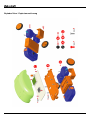
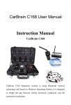
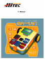
About the manual
This manual is organized in order of level of difficulty and different uses of MA-VIN.
Precautions
This manual contains crucial information including the precautions that must be taken seriously to insure trouble free
operation of MA-VIN robot as well as prevent damage for the user and others. In addition, this user manual should be
placed in a place where it is accessible to as many users as possible.
When inner content of battery is accidentally put into one’s eyes, wash the eyes immediately with clean, flowing
water and follow the procedures given by a medical doctor.
It may cause serious damage to the eyes if kept untreated.
When inner content of battery is exposed to skin or clothes, make sure to wash with clean, flowing water.
It may cause damage to skin if put unwashed.
Do not dissemble or tamper with any part of the machine.
It might cause electrocution or damage due to malfunction of the machine.
Do not touch any inner part of the machine exposed due to external damage such as fall.
It might cause electrocution or damage on user. Take out the batteries and ask for professional help from Multiplex
Modellsport GmbH & Co.KG
Do not exert any extreme pressure on the machine.
It might cause damage or fire.
Do not apply any inflammable chemical such as benzene, paint thinner etc. Do not place any part of the machine
near naphthalene or camphor.
Plastic case might melt or cause fire and electrocution. When not in use, take out the batteries.
Keep parts away from any infant.
Make sure that batteries are inserted the right way round and with the correct polarity.
Do not mix new and used batteries or mix batteries of different types - always use a complete set of new
batteries of the same type when replacing batteries.
Do not recharge non-rechargeable batteries.
Use the correct charger for the size and type of rechargeable battery and always remove rechargeable batteries
from the toy before recharging them.
Remove exhausted batteries from the product.
In use of a power pack, we recommend to use only original power packs from Hitec/Multiplex, in other cases, we can not
take over warranty.
Specifications and Product Design are subject to change without prior notice
Before Reading the MA-VIN Manual
Our contemporary society is swiftly changing to accommodate not only the ever increasing amount of information but also
the ubiquitous intelligent machines. Constituents of the society now daily struggle to more efficiently handle the enormous
amount of information as well as better satisfy individual needs.
In this new era of ‘ubiquitous’ robots, intelligent robots will play a crucial part in improving people’s lives. The intelligent
robots, also referred to as ‘personal robots’, will therefore play a crucial role in our future society, altering our lifestyles,
cultures etc. Combining with already huge multimedia and IT industries, such robots are also expected to rise significantly
in their market values.
Hitec/Multiplex. is willing to take a bold step forward in order to accommodate such changes of our society. Based on our
R&D effort, we create market-based and human-friendly robots. We, as the forerunners in the field of anthropocentric
robotics, will incorporate the diverse contents from informatics, education and entertainment. We promise to bring the
technology together with a suitable market.
Thank you for purchasing the education robot, MA-VIN!
Exploded View / Explosionszeichnung
1.
HOW TO ASSEMBLE MA-VIN BODY..................................................................................................................................... 3
1.1.
2.
HOW TO ASSEMBLE MA-VIN BODY ...................................................................................................................................... 3
MA-VIN COMPONENTS ............................................................................................................................................................ 5
2.1.
PRODUCT COMPONENTS ......................................................................................................................................................... 5
2.1.1. Components list................................................................................................................................................................. 5
2.1.2. MA-VIN Controller Body .................................................................................................................................................. 5
2.1.3. Input/Output Module Function ......................................................................................................................................... 6
2.1.4. How to Connect Modules .................................................................................................................................................. 7
2.1.5. Using Connection Port...................................................................................................................................................... 7
2.2.
INSTALLING MA-VIN ROBOTICS LAB ............................................................................................................................... 8
2.2.1. Before Installing................................................................................................................................................................ 8
2.2.1.1.
2.2.1.2.
2.2.2.
Installing ........................................................................................................................................................................... 8
2.2.2.1.
2.2.2.2.
2.2.2.3.
3.
What is MA-VIN ROBOTICS LAB? ......................................................................................................................................... 8
MA-VIN ROBOTICS LAB User System Requirements ............................................................................................................ 8
Installing USB to USB-UART Bridge Driver............................................................................................................................. 8
Installing MA-VIN ROBOTICS LAB ........................................................................................................................................ 9
Installing USB Drive Manually................................................................................................................................................. 12
BASIC USES OF MA-VIN ROBOTICS LAB.......................................................................................................................... 17
3.1.
MA-VIN ROBOTICS LAB CONFIGURATIONS .................................................................................................................... 17
3.1.1. Screen Display ................................................................................................................................................................ 17
3.1.2. Menu Display .................................................................................................................................................................. 17
3.1.2.1.
3.1.2.2.
3.1.2.3.
3.1.2.4.
3.1.2.5.
3.1.3.
File(F) ....................................................................................................................................................................................... 17
Source(S) .................................................................................................................................................................................. 19
Tool(T)...................................................................................................................................................................................... 19
View(V) .................................................................................................................................................................................... 20
Help(H) ..................................................................................................................................................................................... 20
Modules : Logic Module, Branch Module, Output Module ............................................................................................ 21
3.1.3.1.
3.1.3.2.
3.1.3.3.
Logic Module............................................................................................................................................................................ 21
Output Module .......................................................................................................................................................................... 22
Module Properties and Programming Result............................................................................................................................. 23
3.2.
PROGRAMMING IN MA-VIN ROBOTICS LAB (BASICS OF MOTION MODULE)................................................................... 23
3.2.1. Arranging Modules ......................................................................................................................................................... 23
3.2.2. Converting Programming into Machine Language ........................................................................................................ 24
3.2.3. Downloading Compiled Program to MA-VIN................................................................................................................. 25
4.
PROGRAMMING IN MA-VIN ROBOTICS LAB (BASICS OF MOTION MODULE)..................................................... 27
4.1.
INSCRIBING LCD .................................................................................................................................................................. 27
4.1.1. Characteristics of LCD Module ...................................................................................................................................... 27
4.1.2. Changing Parameters ..................................................................................................................................................... 27
4.1.3. Programming Completed; D/L to MA-VIN ..................................................................................................................... 27
4.2.
RINGING BUZZER.................................................................................................................................................................. 27
4.2.1. Characteristics of Buzzer Module ................................................................................................................................... 27
4.2.2. Changing Parameters ..................................................................................................................................................... 28
4.2.3. Ringing Buzzer ................................................................................................................................................................ 28
4.3.
LIGHTING LED ..................................................................................................................................................................... 28
4.3.1. Characteristics of LED Module ...................................................................................................................................... 28
4.3.2. Changing Parameters ..................................................................................................................................................... 28
4.3.3. Turning On/Off LED ....................................................................................................................................................... 29
4.3.4. Turning On/Off LED Consecutively ................................................................................................................................ 29
4.4.
COUNT DOWN USING FND................................................................................................................................................... 29
4.4.1. Characteristics of FND Module...................................................................................................................................... 29
4.4.2. Changing Parameters ..................................................................................................................................................... 30
4.4.3. Count Down Using FND................................................................................................................................................. 30
4.5.
RINGING MELODY (1)........................................................................................................................................................... 30
4.5.1. Characteristics of Speaker Module ................................................................................................................................. 30
4.5.2. Changing Parameters ..................................................................................................................................................... 31
4.5.3. Ringing Different Kinds of Melodies............................................................................................................................... 31
4.6.
RINGING MELODY (2)........................................................................................................................................................... 31
4.6.1. Characteristics of Compose Module ............................................................................................................................... 31
4.6.2. Changing Parameters ..................................................................................................................................................... 31
4.6.3. Create Your Own Melody................................................................................................................................................ 32
1 of 43
4.7.
MOVING MA-VIN................................................................................................................................................................ 32
4.7.1. Characteristics of Motor Module.................................................................................................................................... 32
4.7.2. Changing Parameters ..................................................................................................................................................... 32
4.7.3. Spinning MA-VIN in One Direction ................................................................................................................................ 32
4.7.4. Move MA-VIN Forward/Backward/Right/Left ................................................................................................................ 32
5.
PROGRAMMING IN MA-VIN ROBOTICS LAB (BASICS OF SENSOR MODULE)...................................................... 33
5.1.
MAKING DOORBELL USING TOUCH SENSOR (1) ................................................................................................................... 33
5.1.1. Characteristics of Touch Sensor Module ........................................................................................................................ 33
5.1.2. Changing Parameters ..................................................................................................................................................... 33
5.1.3. Doorbell Using Buzzer.................................................................................................................................................... 33
5.1.4. Doorbell Using Melody................................................................................................................................................... 34
5.1.5. Make Your Own Doorbell ............................................................................................................................................... 34
5.2.
ALARM CLOCK ..................................................................................................................................................................... 34
5.2.1. Ringing Melody after 10 Seconds.................................................................................................................................... 34
5.2.2. Ringing Melody in Daylight – Characteristics of CdS Module....................................................................................... 35
5.2.3. Changing Parameters ..................................................................................................................................................... 35
5.2.4. Making Alarm Clock ....................................................................................................................................................... 35
5.3.
BURGLARY ALARM .............................................................................................................................................................. 36
5.3.1. Characteristics of Microphone Module .......................................................................................................................... 36
5.3.2. Changing Parameters ..................................................................................................................................................... 36
5.3.3. Making Burglary Alarm .................................................................................................................................................. 36
5.4.
REMOTE CONTROLLED MA-VIN.......................................................................................................................................... 37
5.4.1. Characteristics of Remote Control Module..................................................................................................................... 37
5.4.2. Changing Parameters ..................................................................................................................................................... 37
5.4.3. Changing FND Number Using Remote Control ............................................................................................................. 37
5.4.4. Remote Controlled MA-VIN............................................................................................................................................ 38
6.
PROGRAMMING IN MA-VIN ROBOTICS LAB (APPLICATIONS OF FRONT/REAR MODULE)............................ 39
6.1.
CHARACTERISTICS OF FRONT/REAR MODULE ...................................................................................................................... 39
6.1.1. Characteristics of Front/Rear Module ............................................................................................................................ 39
6.1.2. Changing Parameters ..................................................................................................................................................... 39
6.1.3. Controlling FND Using Front/Back Module .................................................................................................................. 39
6.2.
MA-VIN AVOID ROBOT ....................................................................................................................................................... 40
6.2.1. Programming Avoid Robot ............................................................................................................................................. 40
6.3.
MA-VINLINE TRACE ROBOT ............................................................................................................................................... 40
6.3.1. Programming Line Tracer .............................................................................................................................................. 41
7.
PROGRAMMING IN MA-VIN ROBOTICS LAB (USE OF APPLICATIONS MODULES) ............................................ 42
7.1.
APPLICATION MODULES ....................................................................................................................................................... 42
7.1.1. Making Application Module............................................................................................................................................ 42
2 of 43
1. How to Assemble MA-VIN Body
1.1. How to Assemble MA-VIN Body
1. Check if you are missing any of the MA-VIN
components
2. Tighten the screws on the battery pack
3. Assemble the left gear box
4. Assemble the right gear box
5. Attach the cover to gear box
6. Screw the cover to the gear box
3 of 43
7. Attach the Front/Rear sensor
8. Take out the main board
9. Attach the main board to the body of MA-VIN
10. Screw the main board to the body
11. Connect LCD, power supply, motor etc. to the
body
12. Put the cover on the body
4 of 43
2. MA-VIN Components
2.1. Product Components
2.1.1. Components list
No.
1
2
3
4
5
6
7
8
9
10
11
12
13
14
15
16
Components
Main Board
Gear Box
Battery Box
Front/Rear Sensor Module
LCD
Wheels
USB Download Cable
Case
Speaker
Buzzer
FND
LED
CDS
Touch Sensor
Switch
Screw
Qty.
1
2
1
1
1
2
1
1
1
1
1
1
1
1
1
14
Usage
Controls MA-VIN
MA-VIN driver motor
AAA 1.5V * 4
Equipped with assistant wheels; perceives front/rear environment
Displays 2*8 letters
MA-VIN driver wheels
Connector to PC
External protection cover
Plays melodies
Buzzes
Displays 0~9, A, B, C, D, F
Controls 4 LED’s
Perceives the light intensity
Perceives touch sense
1~7 switch input
Needed in assembling MA-VIN
2.1.2. MA-VIN Controller Body
5 of 43
No.
Komponente
1
LCD display panel
2
3
4
5
6
7
8
9
10
POWER LED(Red LED)
Power switch
DL Jack
Download LED(Green LED)
Motor Connector
Module Connector
IR Receptor
Microphone
Power Connector
11
Power Jack
Beschreibung
can be personalized. 2 lines, 8 letters each line,
total 16 letters can be displayed
displays the status of power supply by DC 5V
turns on and off the power
connects to download cable
displays the download status
connects DC motor to the MA-VIN body
connects module to KIT(1~5)
receives remote control signal
perceives sound
supplies DC 5V power
supplies DC 5V power (when supplying power
with other adaptors)
2.1.3. Input/Output Module Function
1) Input Module
Typ
Module
Function
controls output according to Tact S/W
input
Switch Module
controls output according to light input
CdS Sensor Module
Touch Sensor Module
Microphone Module
Front/Rear Sensor Module
controls output according to touch sense
input
internally installed in KIT; controls output
according to sound input Schall
installed in frame as a button; total 6 (front
3, rear 3) controls output
2) Output Module
Typ
Module
Function
Buzzer Module
buzzes
FDN Module
displays one digit number, depending on
input value
LED Module
displays 4 LED output values
LCD Module
displays 2 x 8 text
Speaker Module
plays melody; plays 1.5 octave, 18 notes
DC Motor Module
controls output by connector time;
directional control; controls velocity by
variable resistance (optional category)
6 of 43
2.1.4. How to Connect Modules
a. Align the MA-VIN body and the module as shown in (picture) (texts on module and board aligned)
b. Plug the module into any of number from 1 to 5 of MA-VIN Body Module.
c. There are Buzzer Module, LED Module, FND Module, Speaker Module, Touch Sensor Module, CdS Sensor
Module, and Switch Module that could be plugged into MA-VIN Body Module.
d. LCD, Buzzer, Remote Control Receptor are already installed on MA-VIN Body. We currently do not provide
Remote Control Transmitter.
2.1.5. Using Connection Port
Program download cable is installed in the following steps:
a.
b.
c.
d.
Connect the USB cable to USB port of computer.
Connect the other end of USB cable to DL(Download) Jack of MA-VIN control board.
After programming in MA-VIN ROBOTICS LAB, download the program to MA-VIN.
Check the program in MA-VIN.
7 of 43
2.2. Installing MA-VIN ROBOTICS LAB
2.2.1. Before Installing
2.2.1.1. What is MA-VIN ROBOTICS LAB?
MA-VIN ROBOTICS LAB is a software for programming the movements of MA-VIN. Generally, controlled robots need to
be programmed in C programming language. However, such programming requires significant devotion of time and
effort. In order to make programming easier, we have created MA-VIN ROBOTICS LAB in GUI setting. Such icon-based
programming according to different kinds of modules has already made the robotics education experience much more
effective and fun.
2.2.1.2. MA-VIN ROBOTICS LAB User System Requirements
MA-VIN ROBOTICS LAB runs optimally under the following systems.
If lacking any, we recommend upgrading your system.
• 200 MB hard-disk space
• 100 MB hard-disk space
• 256 MB or above RAM
• Intel Pentium III or above processor or compatible processors
• OS Microsoft Windows 2000, XP etc.
.
2.2.2. Installing
Installing MA-VIN ROBOTICS LAB starts with inserting the setup CD into CD-ROM. First install USB to UART Bridge
Driver
2.2.2.1. Installing USB to USB-UART Bridge Driver
Click USB to UART Bridge Driver • CP2101_Drivers.exe.
The window on the right will appear at the beginning of
the driver install process.
The initial screen disappears, and the window on the left
will show. Click ‘next’ to begin installing.
If you agree with license information concerning CP2101
USB to UART Bridge Controller, click ‘Yes’.
8 of 43
Select a folder to install CP2101 USB to UART
Bridge Controller Driver in. Click ‘Next’. Default
folder is “C:\SiLabs\MCU\CP2101”.
CP2101 USB to UART Bridge Controller is being
installed.
2.2.2.2. Installing MA-VIN ROBOTICS LAB
After CP2101 USB to UART Bridge Controller
Driver installation is complete, start MA-VIN
ROBOTICS LAB installation in following order.
Double click Setup.exe in MA-VIN ROBOTICS LAB Setup CD. Click “Next”
9 of 43
Enter your name and the name of your organisation and click “next”.
Select “Complete” Installation and click next. The default folder of installation is “C:\Program Files\MA-VIN”.
10 of 43
Click “Install”. MA-VIN ROBOTICS LAB is being installed.
11 of 43
Installation complete. Click “Finish”.
2.2.2.3. Installing USB Drive Manually
Control Panel • Add New Hardware
12 of 43
If your computer will automatically search for a new hardware to install and shows the CP2101 USB to UART Bridge
Controller Driver window as shown below, skip procedure 3)~6) and start from 7).
If your computer does not automatically search for a new hardware, manual install window as shown below will appear. If
MA-VIN is connected to the PC, select ‘Yes’ as below.
13 of 43
Select ‘CP2101 USB to UART Bridge Controller’ and click ‘Next>’
Install completed
After ‘Add Hardware Wizard’ is completed, ‘Found New Hardware Wizard’ as shown below will appear.
14 of 43
Select ‘(Advanced)’ and click ‘Next>’.
Select the folder that contains the drivers as shown below.
Check if the folder is the right one, and click ‘Next’.
15 of 43
Installing
Installing Hardware is completed when ‘Completing The Found New Hardware’ appears.
16 of 43
3. Basic Uses of MA-VIN ROBOTICS LAB
3.1. MA-VIN ROBOTICS LAB Configurations
3.1.1. Screen Display
1. Main Menu : contains “file”, “source”, “tool”, “view”, and “help”.
2. Tool Bar : icons of the selected menu options
3. Logic Module : includes branch modules and logic modules, such as sensors, needed for programming the
movements of MA-VIN.
4. Output Module : output module of MA-VIN; includes motor and LED modules.
5. Main View : space for programming MA-VIN
6. Module Properties : indicates module’s properties
7. Programming Result : displays MA-VIN ROBOTICS LAB programming process
8. Application Module : functions made by logic modules and output modules can be used as modules.
3.1.2. Menu Display
Knowing different menu options and tool bar buttons is the first step of learning programming. Each “file”, “source”, “tool”,
“view”, and “help” has its own menu within. Click the menu for its submenu. Using icon toolbar can ease the burden of
having to click through the submenus. Once you get used to using MA-VIN ROBOTICS LAB, toolbar will become much
handier than the menu. We will now talk about menu and toolbar buttons :
Main menu and toolbar are as shown as below. The most commonly used menu functions are in icons.
3.1.2.1. File(F)
New, Open, Save These are the most basic functions needed for programming. It opens a new file, opens a created file,
and saves a file.
17 of 43
3.1.2.1.1. New
Creates a blank file. Click the
“new”
icon button or “file” •
Abb. 1 File Æ New
3.1.2.1.2. Open
Opens a created file. Click the icon button or “file” ->”open”, then select a file to open and click “open”
Abb. 2 File Æ Open
3.1.2.1.3. Save
Saves a file. Click the icon button or „file“ -> „save“. Give the file a name in “filename”. There is no need for adding “.izi”
extention.
3.1.2.1.4. Save As
Save As : Similar to “save”, “save as” saves a file in a different name. Click “file” • “save as”. Name the file in
“file name” and click “save”.
18 of 43
3.1.2.1.5. Make app module
Making Application Modules : Menu used in creating application modules for programming in MA-VIN ROBOTICS LAB.
Details will be described in “VI. Programming in MA-VIN ROBOTICS LAB (Use of Application Modules)”.
3.1.2.2. Source(S)
View Source, Edit Source, External Source not offered.
3.1.2.3. Tool(T)
Logic Check, Simulation, Compile, Download
‘Logic Check’ verifies the legitimacy of the programming language. ‘Compile’ turns icon-based language into C
programming language. ‘Download’ transmits the program to robot.
3.1.2.3.1. Logic Check
This menu checks if the programming is done in logical
fashion. Press the button as shown in the picture or ‘tool’
→ ‘logic check’.
3.1.2.3.2. Simulation
Simulates how the program will run in reality.
3.1.2.3.3. Compile
Icon-based programming done in MA-VIN ROBOTICS
LAB gets re-written in C language. Press the button as
shown in the picture or ‘tool’ • ‘compile’.
19 of 43
3.1.2.3.4. Download
Program written in C language using ‘Compile’ is sent to
MA-VIN. ‘Download’ saves the program done in PC into
MA-VIN via USB cable. Press the button as shown in the
picture or ‘tool’ • ‘download’.
3.1.2.4. View(V)
In a setting that requires relatively small number of menu icons, use ‘zoom in’ to make the size of icons bigger. In a
setting that requires relatively large number of menu icons, use ‘zoom out’ to make the size of icons smaller.
3.1.2.4.1. Zoom In
Zoom In : Zooms in and make the size of ‘Main View’
icons bigger. Press the button as shown in the picture or
‘view’ • ‘zoom in’.
3.1.2.4.2. Zoom Out
„Zoom Out : Zooms out and make the size of ‘Main
View’ icons smaller. Press the button as shown in the
picture or‘view’ • ‘zoom out’.
Abb. 3 Zoom Funktion
3.1.2.5. Help(H)
Unter diesem Menüpunkt finden Sie die Funktionen „Content“, „Search“, „Online Update“ und „MA-VIN info“. Mit diesen
Funktionen können Hilfethemen andere Informationen eingesehen werden.
20 of 43
3.1.3. Modules : Logic Module, Branch Module, Output Module
In order to make programming easier, MA-VIN ROBOTICS LAB divides the modules into categories of function. Generally
speaking, a module is either a ‘Logic Module’, such as “start”, “end”, “repeat” and “delay”, a ‘Branch Module’, such as
“remote control” and “touch sensor”, or a ‘Output Module’ which controls the movement of MA-VIN.
3.1.3.1. Logic Module
Logic Module icons are purple. Logic Modules include ‘Logic Modules’, such as “start” and “end”, and ‘Branch Modules’,
such as “remote control” and “touch sensor”.
3.1.3.1.1. Logic Module
Indicates starting and end point of MA-VIN program.
Modul
Module
Function
Start
Program start
Repeat
Repeats the program as many times as the whole number
indicates
Delay
Whole numbers from 1 to 65,535 can be input. Its unit is
millisecond (1/1000 sec).
End
Program end
3.1.3.1.2. Branch module
Branch Module” is also in purple like “Logic Module”. It is a group of modules that control external sensors which MA-VIN
uses.
Modul
Module
Function
Remote
Depending on the input value of remote control, it branches off
either to down or right.
Touch S/C
Depending on the pressure exerted on the touch sensor, it
branches off either to down or right.
CDS S/C
Depending on the light intensity, it branches off either to down or
right.
MIC
Depending on the sound intensity value perceived by the
microphone, it branches off either to down or right.
21 of 43
Photo
Depending on the IR value received from 3 front and 3 rear
sensors, it branches off either to down or right.
Switch
Depending on whether the switch is on or not, it branches off
either to down or right
3.1.3.2. Output Module
Modules icons are in red. They carry out different kinds of output commands that MA-VIN has.
Modul
Module
Function
Motor
Motor operates according to velocity and direction input values.
LED
Controls LED on/off
Speaker
Plays a selected tune. Currently MA-VIN ROBOTICS LAB offers
10 different tunes.
Buzzer
Buzzes as many times as the input number indicates.
LCD
Displays texts on MA-VINLCD. 2x8 texts can also be displayed.
Music
User can compose a simple tune.
FND
Displays a number 0~9
22 of 43
3.1.3.3. Module Properties and Programming Result
Every Module, except “start” and “end” of Logic Module, has its own properties. We will talk more about their properties in
the corresponding module program sections. Also, ‘Programming Result’ shows the status of programming when
processing “logic check”, “compile”, “download”. Details will be described in the next chapter.
3.2. Programming in MA-VIN ROBOTICS LAB (Basics of Motion Module)
MA-VIN programming procedure in MA-VIN ROBOTICS LAB can be briefly explained as such : arrange needed modules
in “Main View”
• input the properties of the modules
• connect the modules together.
After selecting and connecting the modules, use ‘Compile’ to turn icon-based program into C language program, and
finally download the program from PC to MA-VIN.
3.2.1. Arranging Modules
It is the most basic step of programming in MA-VIN ROBOTICS LAB. Select and arrange the modules as needed. In
order to move the robot deliberately, arrange the modules in a logical order.
1. According to the set up of the program, arrange the modules in “Main View”. Left-click the module you would like
to move and then drop it in a space by clicking again.
2. After arranging the modules, connect them together. To connect them together, click the bottom of a module and
click the top of another module you would like to connect to. In case of Branch Modules, you could also connect
to another module from its right side, depending on its compatibility.
23 of 43
3. After connecting the modules, select their properties in ‘Modules Properties’.
3.2.2. Converting Programming into Machine Language
This procedure converts the icon-based programming language into machine language and is composed of internal
programming grammar check and compile process. However, in MA-VIN ROBOTICS LAB process mentioned above is
automatically carried out from “compile” button in toolbar, and therefore the user can easily convert icon-based language
into machine language without any professional knowledge of programming.
24 of 43
3.2.3. Downloading Compiled Program to MA-VIN
This process enables carrying out the commands of MA-VIN by saving the program to the robot. After connecting PC and
MA-VIN with USB cable, press “download” icon of toolbar.
25 of 43
Note : When MA-VIN and PC are not connected or MA-VIN’s power is not turned on, windows shown below will appear.
PC and MA-VIN are connected, but MA-VIN is not turned on.
PC and MA-VIN are not connected.
26 of 43
4. Programming in MA-VIN ROBOTICS LAB (Basics of Motion Module)
4.1. Inscribing LCD
4.1.1. Characteristics of LCD Module
LCD Module displays 2x8 texts. Texts to be displayed
should be input within “ ”. LCD Module accepts only
English letters, and distinguishes between capitalized
and non-capitalized letters.
4.1.2. Changing Parameters
Left-click the LCD module to see LCD properties as
shown in the picture. Try inputting letters as such : write
“MyNameIs” in Text(line 1) and “MA-VIN” in Text(line 2).
4.1.3. Programming Completed; D/L to MA-VIN
Once done inputting properties of LCD module,
complete the programming process as shown in the
diagram. Then, press ‘compile’ and ‘download’ to
download program to MA-VIN. When download is
completed, LCD will display texts as shown in the
picture.
I
4.2. Ringing Buzzer
4.2.1. Characteristics of Buzzer Module
Buzzer module controls ringing of the buzzer. Buzzer
can only make one kind of sound.
27 of 43
4.2.2. Changing Parameters
Left-click the buzzer module to see the properties of
buzzer module. “Position” indicates where the module is
located and ranges from 1 to 5. “Number” determines
how many times the buzzer will buzz according to the
whole number input.
4.2.3. Ringing Buzzer
When done inputting the properties of buzzer module,
complete the modules as shown in the diagram. Then,
press ‘compile’ and ‘download’ to download the program
to MA-VIN. Once the download is completed, buzzer
module connected to MA-VIN will buzz according the
input values of properties.
4.3. Lighting LED
4.3.1. Characteristics of LED Module
LED Module controls on and off of LED. There are total 4 LED’s, and each could operate separately or together.
4.3.2. Changing Parameters
Left-click LED module to see the LED module properties. Then, select the position of the module from 1 to 5. “Value”
controls the four LED’s. It can control them separately or together.
28 of 43
4.3.3. Turning On/Off LED
Arrange the LED modules, compile and download to
MA-VIN, so that the four LED’s turn on and off together.
The four LED’s will turn on and off together. However,
the time for which the LED’s are on will be very short.
Can we control the duration? We can not control the
duration in LED module, because there only exists on
and off function of LED. Then, how can we control the
duration? We had learnt “delay module” of “logic
module”. “Delay module” can control the delay time from
1 to 65,535 millisecond. Therefore, by arranging a delay
module after a LED module, we can program LED to
turn on for the whole second. Complete the program
with “delay module”. Then, ‘compile’ and ‘download’ to
transmit the program to MA-VIN. Once the download is
completed, MA-VIN’s LED will turn on for a second and
will turn off
4.3.4. Turning On/Off LED Consecutively
Let us program the LED module, so that the four LED’s turn on and off consecutively. We can use the way we turned on
and off all four LED’s.
After completing the program above, download it to MA-VIN and check how the LED’s turn on and off. LED’s will turn on
consecutively from 1 to 4, and all will turn off. Thus, we can use delay modules to control the duration for which the LED’s
are on.
4.4. Count Down Using FND
4.4.1. Characteristics of FND Module
FND, also known as ‘7 segment’, is a display device for numbers. Like a digital watch, FND displays a number using the 7
segments in it. Each FND of MA-VIN displays one number.
Displaying number 0 to 9 using FND module
29 of 43
4.4.2. Changing Parameters
Left-click the FND module to see the module properties.
“Position” ranges from 1 to 5 and represents the location
of FND. “Number” is the number input that is displayed
on FND itself.
4.4.3. Count Down Using FND
In order to device a count down machine using FND, arrange the modules as shown in the picture below. When done
with programming, download the program to MA-VINto see how the numbers of FND module change.
4.5. Ringing Melody (1)
4.5.1. Characteristics of Speaker Module
Speaker module plays a selected melody. Currently, MA-VIN ROBOTICS LAB provides up to 10 different melodies.
30 of 43
4.5.2. Changing Parameters
Left-click the speaker module to see the properties.
“Position” , ranging from 1 to 5, indicates the location of
the speaker module. “Melody Type”, ranging from 1 to
10, represents different kinds of melodies to be played.
4.5.3. Ringing Different Kinds of Melodies
In order to play melodies using speaker module, arrange
the modules as shown in the picture. Once done with
programming, download it to MA-VIN and listen to
different melodies being played.
4.6. Ringing Melody (2)
4.6.1. Characteristics of Compose Module
Compose module like speaker module can produce sound through MA-VIN. However, compose module, unlike speaker
module which plays the whole melody, plays only the selected notes. Therefore, the user can compose and produce
his/her own music.
4.6.2. Changing Parameters
Left-click the compose module to see the properties. “Position”, ranging from 1 to 5, represents the location of the
th
module. “Pitch” ranges from 1 octave 1 G to 3 E. “Rhythm” ranges from the 32 note to dotted half note.
31 of 43
4.6.3. Create Your Own Melody
Using compose modules, try creating your own melody.
4.7. Moving MA-VIN
4.7.1. Characteristics of Motor Module
Motor module is used to operate one of the basic devices of MA-VIN, motor. Also, it is used to connect more than one
motors to module.
4.7.2. Changing Parameters
Left-click motor module to see the properties. “Position”,
ranging from 1 to 5, represents the position of the
module. For the basic component motor of MA-VIN,
select “basic motor” (options of having motors 1 to 5 will
be added later on). “Direction” has the options of forward
and backward. “Select Motor” is for the basic element
motor of MA-VIN
and includes “Right motor” and “Left motor”. “Velocity”
controls how fast the motor rotates, and the possible
input value ranges from 1 to 17.
4.7.3. Spinning MA-VIN in One Direction
In order to make MA-VIN
spin in one direction, arrange the modules as shown in
the diagram. Once done programming, download the
program to MA-VIN and see how MA-VIN moves.
4.7.4. Move MA-VIN Forward/Backward/Right/Left
Using motor modules, make MA-VIN move in ‘+’ shaped path. Once done programming, download the program to MAVIN and see how MA-VIN moves.
32 of 43
5. Programming in MA-VIN ROBOTICS LAB (Basics of Sensor Module)
5.1. Making Doorbell Using Touch Sensor (1)
5.1.1. Characteristics of Touch Sensor Module
Touch sensor module has a touch sensor on its top. If you touch silver-colored part of the touch sensor, it perceives the
touch, and LED of the module turns on.
5.1.2. Changing Parameters
Left-click touch sensor module to see the module
properties. “Position” ranges from 1 to 5 and represents
where the module is located. “Affirmation condition”
shows either ‘true’ or ‘false’. When it is ‘true’, the touch
sensor perceived the touch, and when it is ‘false’, the
touch was not perceived.
5.1.3. Doorbell Using Buzzer
In order to make a doorbell that buzzes when touching
the touch sensor using touch sensor module, arrange
the touch sensor modules and buzzer modules as
shown in the next page. Also, try using ‘repeat’ modules
(page 28) to program a doorbell. Once done with
programming, download the program to MA-VIN and see
how it operates.
33 of 43
5.1.4. Doorbell Using Melody
In order to make a doorbell that plays a melody and
shows “Guest” on LCD module (page 35), arrange the
modules as shown in the next page. Also, as in
“Doorbell Using Buzzer”, try using ‘repeat’ modules to
program a doorbell. Once done with programming,
download the program to MA-VIN and see how it
operates.
5.1.5. Make Your Own Doorbell
Make your own doorbell that plays a melody and shows “Guest” on LCD module by using touch sensor module and
compose module. Once done with programming, download the program to MA-VIN and see how it operates.
5.2. Alarm Clock
5.2.1. Ringing Melody after 10 Seconds
Program MA-VIN to play a melody 10 seconds after it starts moving. Also, using FND module, program MA-VIN to
countdown from 9 to 0 and play the melody when it is done counting. Once programming is done, download it to MA-VIN
and see it operate.
34 of 43
5.2.2. Ringing Melody in Daylight – Characteristics of CdS Module
In section (1), we have made a alarm that rings at a specific time. Now, let us make an alarm system that rings when it is
exposed to light. In order for MA-VIN to determine whether there exists light or not, we need to use a CdS module. CdS
cell of the module uses the chemical known as Cadmium Sulfide(CdS). CdS, because of its photoconductivity effect, has
a tendency to have lower electrical resistance when exposed to light. Using this characteristic of CdS, we can make a
light sensor.
5.2.3. Changing Parameters
Left-click the module to see the properties of CdS module. “Position”, ranging from 1 to 5, represents where the module is
located. “Luminance” determines how strong the light exposure has to be to trigger the response from MA-VIN.
“Affirmation condition” displays either true or false. When the “Affirmation condition” is true, it means that the light
exposure is greater than or equal to the “Luminance” of the module. When it is false, it means that the light exposure is
less than the set intensity value.
5.2.4. Making Alarm Clock
Let us make an MA-VIN alarm clock that rings when the sun rises. Select the light intensity of the sunrise as “light
intensity” in the module properties. When done with programming, download it to MA-VIN and see how it operates.
35 of 43
5.3. Burglary Alarm
5.3.1. Characteristics of Microphone Module
Microphone module is a type of sensor module that reacts to the ambient sound. It also reacts differently to different
levels of sound intensity. Microphone module, unlike any other module, is internally installed in MA-VIN Body (PCB).
5.3.2. Changing Parameters
Left-click the microphone module to view the properties.
“Sound intensity” ranges from 1 to 5. “Affirmation
condition”can have either ‘true’ or ‘false’. When
“Affirmation condition” is ‘true’, the sound intensity is
greater than or equal to the set value in “Sound
intensity”. When it is ‘false’, sound intensity is less than
the set value. The reason there is no “location” category
in microphone module is that microphone module is
installed internally in MA-VIN.
5.3.3. Making Burglary Alarm
Let us make an MA-VIN burglary alarm program capable of sensing the unexpected presence of noise at night. When a
burglar enters a house, some noise is most likely to be made. Using microphone module of MA-VIN, we can devise a
burglary alarm. After the sun sets and night arrives, MA-VIN burglary alarm will be activated. Let us program MA-VIN so
that when there is no burglar(no ambient sound), LED module 1 lights up, and when MA-VIN senses a presence of a
burglar, LCD displays “Burglar” and buzzer beeps. Also, let us program MA-VIN so that it will return from beeping and
displaying “Burglar” to its normal status when touched on its touch sensor. Arrange the modules as shown in the diagram
on the next page. When the programming is done, download the program to see how MA-VIN operates
36 of 43
5.4. Remote Controlled MA-VIN
5.4.1. Characteristics of Remote Control Module
‘Remote Control Module’ enables controlling MA-VIN using a remote controller. Generally, remote controllers use infrared
or RF(Radio Frequency). Infrared emitted from remote controller is perceived by the receiver located in MA-VIN Body
(PCB).
5.4.2. Changing Parameters
Left-click the remote control module to view the properties of the module. “Setting Value” lets you to choose the function
keys of remote control. “Affirmation condition” consists of ‘true’ and ‘false’. When it is ‘true’, it indicates that the input into
the module matches the function key set in “Setting Value”. When it is ‘false’, it means that the input value does not match
the “Setting Value”.
5.4.3. Changing FND Number Using Remote Control
Let us program MA-VIN so that FND number can be changed by using remote control. In “Set Value” of the module,
“Move Forward” will be represented by ‘1’, “Move Backward” by ‘2’, “Move Left” by ‘3’, and “Move Right” by ‘4’.
Also, when there is no signal input at all, let LCD module of the MA-VIN display “Nothing”. Arrange the modules as shown
in the diagram in the next page. When done with programming, download the program to see how MA-VIN operates.
37 of 43
5.4.4. Remote Controlled MA-VIN
Let us control MA-VIN with Remote Control. Arrange the modules as shown in the next page to allow MA-VIN to move
forward, backward, and turn right and left. When done with programming, download the program to see how MA-VIN
operates.
38 of 43
6. Programming in MA-VIN ROBOTICS LAB (Applications of Front/Rear Module)
6.1. Characteristics of Front/Rear Module
6.1.1. Characteristics of Front/Rear Module
Front/Rear Module is an application module of MA-VIN that is composed of six luminescent diodes and phototransistors.
Three of them are located on the front part of MA-VIN, and the rest three on the rear. The front modules perceive the
obstacles that lie ahead in the course of MA-VIN’s movement. The modules on the bottom of MA-VIN check the condition
of the surface on which MA-VIN moves.
6.1.2. Changing Parameters
Left-click the Front/Rear module to view the
module properties. “Sensor Direction” represents
the direction(either ‘Forward or ‘Backward) of
infrared module, which is a part of the Front/Back
module. “Sensor Status” can identifies a specific
situation for MA-VIN to recognize. If the
“Affirmation condition” is ‘true’, Front/Back module
matches the situation identified in “Sensor Status”.
If it is ‘false’, the module does not match the
“Sensor Status”.
6.1.3. Controlling FND Using Front/Back Module
Let us program the MA-VIN that changes FND number using FND module and Front/Back module. Denote each part of
MA-VIN with FND numbers; Front/Back module’s ‘front’ will have 1 to 3 FND numbers from its left to right; ‘rear’ will have
4 to 6 from left to right. Also, when the Boolean Statements of “Sensor Status” are all ‘false’, the module does not match
the situation identified in “Sensor Status”. Arrange the modules as shown in the diagram in the next page.
Download the program to ER6 and see how it operates.
39 of 43
6.2. MA-VIN Avoid Robot
Let us make an Avoid Robot that dodges any obstacle that is in its course of movement using motor module. It will
perceive the presence of obstacles by its Front/Rear modules.
6.2.1. Programming Avoid Robot
In order to make an MA-VINAvoid Robot, the sensor direction of Front/Rear module has to be ‘Forward’, and depending
on the situations defined in “Sensor Status”, MA-VIN’s movements have to be controlled. Arrange the modules as shown
in the next page and download the program to MA-VINto see how it operates. In order to figure out which infrared sensor
of Front/Back module was perceived by MA-VIN, let us program MA-VINusing FND modules.
6.3. MA-VINLine Trace Robot
Let us create a Line Trace Robot that traces a line and moves along the line using motor module of MA-VIN. Using
Front/Back module, create a robot that perceives the line and dodges it.
40 of 43
6.3.1. Programming Line Tracer
In order to program a Line Trace Robot, “Sensor Direction” of Front/Back module has to be ‘backward’. Arrange the
modules as shown in the previous page. Download the program to MA-VIN and see how it operates. In order to visually
be able to determine whether infrared signal was received or not, create a program that uses LED module.
Abb. 4 Beispiel Folgen einer Linie
41 of 43
7. Programming in MA-VIN ROBOTICS LAB (Use of Applications Modules)
7.1. Application Modules
7.1.1. Making Application Module
Select ‘Making Application Modules’ in the main menu
After changing the application module name, save it.
42 of 43
Click Application Output Module Lab to view the Application modules. Arrange the modules as shown below and
download the program to MA-VIN.
43 of 43