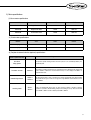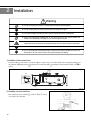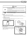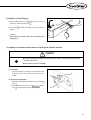
1
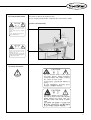
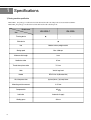
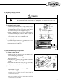
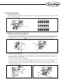
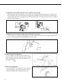
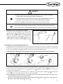
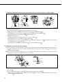
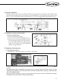
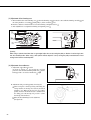
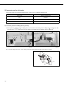
USER ’
S
MANUAL
KM-591BL-7
Long Arm Type, 1 Needle, UnisonFeed Lock Stitch Machine With
Vertical Large Hook and an
Automatic Thread Trimmer
KM-591BL
Long Arm Type, 1 Needle, UnisonFeed Lock Stitch Machine with
Vertical Large Hook
SUNSTAR MACHINERY CO., LTD.
1) FOR AT MOST USE WITH EASINESS,
PLEASE CERTAINLY READ THIS MANUAL
BEFORE STARTING USE.
2) KEEP THIS MANUAL IN SAFE PLACE
FOR REFERENCE WHEN THE MACHINE
BREAKS DOWN.
MME-050509
lity
a
u
tQ
Besst Pricevice
Be st Ser
Be
1. Thank you for purchasing our product. Based on the rich expertise and
experience accumulated in industrial sewing machine production, SUNSTAR
will manufacture industrial sewing machines, which deliver more diverse
functions, high performance, powerful operation, enhanced durability, and
more sophisticated design to meet a number of user’s needs.
2. Please read this user’s manual thoroughly before using the machine. Make
sure to properly use the machine to enjoy its full performance.
3. The specifications of the machine are subject to change, aimed to enhance
product performance, without prior notice.
4. This product is designed, manufactured, and sold as an industrial sewing
machine. It should not be used for other than industrial purpose.
R
SUNSTAR MACHINERY CO., LTD.
Contents
Safety Regulations for Machines ································4
1. Specifications
1) Sewing machine specifications
8
2) Motor specifications
9
2. Installation
1) Installation of the machine head
10
2) Installation of power switch box
10
3) Oil supply
11
4) Belt tension adjustment
11
5) Installation of program unit
12
6) Installation of belt cover
12
7) Installation of thread stand
12
8) Installation of knee lifting pad
13
9) Installation of air pressure related parts and checking their functions (optional)
13
3. Adjustment of sewing machine
1) Needle insertion
14
2) Needle Bar adjustment
14
3) Regulating timing of needle and hook
14
4) Regulating oil supply to hooks
15
5) Lower thread winding and adjustment
15
6) Lower thread hanging and tension adjustment
16
7) Upper thread hanging
16
8) Thread tension adjustment
17
9) Presser foot pressure adjustment
18
10) Stitch length adjustment
18
11) Adjustment of feed dog height and inclination
19
12) Adjustment of main and auxiliary presser foot
19
13) Adjustment of main presser foot movement
20
14) Feed cam adjustment
21
15) Adjustment of reverse solenoid location
21
16) Adjustment of trimming device
21
17) Adjustment of mes pressure
23
18) Changing moving mes
23
19) Changing fixed mes
23
20) Appropriate speed for stitches lengths
24
21) Automatic presser foot lifting device (optional)
24
Safety Regulations for Machines
Safety Regulations for Machines The safety marks are defined as danger, warning and caution.
In case the regulations are not followed, it will bring about physical injuries or mechanical damage.
The safety marks and symbols are as follows.
[Meaning of Safety Sign]
Danger
The contents of this mark should be observed clearly.
Or users are apt to be killed or suffer severe physical injuries.
Warning
The content of this mark should also be observed, otherwise users are likely to die
or suffer severe physical injuries.
Caution
The content of this mark should also be observed, otherwise it will bring about
the physical injuries or the mechanical damage.
[Meaning of Marks]
This mark means a 'must-not.'
This mark means a 'must' for safety.
This mark should be observed, or users are likely to be struck by electricity.
4
1-1) Machine Transportation
Danger
1-2) Machine Installation
Caution
The person who knows the safety regulations well should transport machines. In case the
machines are transported, the following directions should be observed.
ⓐ At least 2 persons should work together.
ⓑ In case the machine should be transported, please wipe the oil covered on the machine to prevent the
accident.
Because the physical damage such as the functional obstacles and breakdowns are likely
to occur in compliance with the condition of installing the machine, the following
preconditions should be fulfilled.
ⓐ Please keep the order from top to bottom when unpacking the package. Especially, mind that the nail
on the boxes.
ⓑ Because machines are apt to be contaminated and corroded by dust and moisture, you should install
the climate controller and should clean the machines regularly.
ⓒ Keep the machines out of the direct rays of the sun.
ⓓ Keep both sides and the backside of the machines off at least 50cm from the wall to secure enough
space to repair.
ⓔ Don't run the machine near the places with the dangers of explosion.
Don't run the machine near the places with the dangers of explosion, including the places where the
spraying product like aerosol are used in large quantities or oxygen are dealt with, unless the exact
actions concerning the operation are guaranteed to avoid the explosion.
ⓕ Because of the peculiarity of the machine, any illuminators are not equipped. So, users should install
the lighting apparatus around the working area.
[Note] The details about the installment of the machine are described in No. 2 Installment of
Machine.
1-3) Troubleshooting
Danger
In need of troubleshooting, it should be done by the trained A/S engineer of our company.
ⓐ Ahead of cleaning and repair, be sure to shut off the power supply. And wait for about 4 minutes till the
machine discharges completely.
ⓑ Even a part or all of the machine should not be modified without any consultation with our company.
ⓒ In case of repair, you should change the damaged part into the standard article of our company.
ⓓ After repair, please put again the safety cover disjointed while repairing.
5
1-4) Machine Operation
Warning
KM-591BL series are manufactured for industry use to sew textiles and other similar
material. In case of running the machine, users should observe the following things.
ⓐ Ahead of operating the machine, please read the manual and understand fully the details on its operation.
ⓑ Don't forget to put on the garment suited for the safe work.
ⓒ Keep your hands or a part of the body away from the running part of the machine like a needle, hook,
thread take-up spring and pulley etc.
ⓓ Don't remove any kind of cover for safety while running the machine.
ⓔ Be sure to connect the earthed line.
ⓕ Before opening the electric box such as a control box, be sure to shut off the power supply and make
sure that the power switch should be put on "off."
ⓖ When threading the needle or before checking after sewing, be sure to stop the machine.
ⓗ Don't switch on the power supply with the foot on the pedal.
ⓘ Don't run the machine when the cooling fan are not running. Be sure to clean the air filter in the control
box once a week.
ⓙ If possible, keep off from the strong electronic wave like a high frequency welding machine.
Warning
1-5) Safety Device
Warning
Fingers or hands can be cut off because of the belt. So be sure
to run the machine after covering the safety cover, and in case of
checking or regulating, be sure to switch off the power supply.
ⓐ Safety Label : Suggestions while running the machine are stated
ⓑ Thread take-up lever cover : The device to prevent the human body from touching the thread take-up
lever
ⓒ Belt cover : The device to prevent hands, feet and clothing from getting jammed by the belt
ⓓ Finger guard : The device to prevent fingers from contacting the needle
ⓐ
ⓑ
ⓒ
ⓓ
6
1-6) Precaution Mark Position
CAUTION
경 고
"Precautions" is adhered to the machine for safety.
In case of starting to run the machine, read the directions of "Precautions" carefully.
[Position of Precaution Mark]
Do not operate without finger guard and
safety devices. Before threading, changing
bobbin and needle, cleaning etc. switch off
main switch.
손가락 보호대와 안전장치 없이 작동하지
마십시오.
실, 보빈, 바늘교환시나 청소전에는 반드시 주
전원의 스위치를 꺼 주십시오.
CAUTION
경 고
Hazardous voltage will cause injury.
Be sure to wait at least 360 seconds before
opening this cover after turn off main switch
and unplug a power cord.
고압 전류에 의해 감전될 수 있으므로 커버를
열 때는 전원을 내리고 전원 플러그를 뽑고 나
서 360초간 기다린 후 여십시오.
1-7) Content of Precaution
CAUTION
경 고
Notice
Do not operate without finger guard
and safety devices. Before threading,
changing bobbin and needle, cleaning
etc. switch off main switch.
손가락 보호대와 안전장치 없이 작동하지 마
십시오.
실, 보빈, 바늘교환시나 청소전에는 반드시
주전원의 스위치를 꺼 주십시오.
CAUTION
경 고
Hazardous voltage will cause injury.
Be sure to wait at least 360 seconds
before opening this cover after turn
off main switch and unplug a power
cord.
고압 전류에 의해 감전될 수 있으므로 커버
를 열 때는 전원을 내리고 전원 플러그를 뽑
고 나서 360초간 기다린 후 여십시오.
7
1
Specifications
1) Sewing machine specification
KM-591BL-7 Long arm type, 1-needle unison feed lock stitch machine with vertical large hook and an automatic thread trimmer
KM-591BL Long arm type, 1-needle unison feed lock stitch machine with vertical large hook.
Model name
Item
Trimming device
KM-591BL
★
Climb device
★
Use
Medium to heavy weight material
Sewing speed
Max. 2,400 spm
Maximum stitch length
9 mm
Needle bar stroke
35 mm
Thread take-up lever stroke
71.5 mm
Hook
Vertical large hook
Needle
DPX17 #16~23 (Standard #23)
Lift of the presser foot
(by hand) 9mm, / (by knee) 16mm
Alternating vertical movement
2~5.5 mm
Compressed air
8
KM-591BL-7
0.5
Lubrication
Automatic oil supply
Working space
322 mm
2) Motor specifications
(1) Servo motor specifications
MODEL
VOLT
WATT
HERTZ
S3M55-1B
Single Phase 110V
550W
50/60 Hz
S3M55-2B
Single Phase 220V
550W
50/60 Hz
S3M55-3B
Three Phase 110V
550W
50/60 Hz
MODEL
VOLT
WATT
HERTZ
HEC-1705 (Single Phase)
110V/220V
400W
50/60 Hz
HEC-1706 (Triple Phase)
110V/220V
400W
50/60 Hz
(2) Clutch motor specifications
(3) Peripheral automatic device (optional) specifications
Name of optional devices
Model
Auto Knee
Lifting System
Usage
Air pressure cylinder working structure where the presser foot is automatically lifted by one
backward pedal.
Production Counter
SCOUN-1
A production counting system where the completed amount is displayed in the program unit
panel. Addition, subtraction and amended inventory are also displayed in addition to
implementation ratio.
Material Edge Sensor
SEDG-1
SEDG-2
By detecting the fabric s edge or thickness, the machine automatically stops without halting
the pedal. The two types of sensors are edge sensor type SEDG-1 and the thickness sensor
type SEDG-2.
Standing Pedal
SPDL-1
SPDL-2
This is an indispensable device when one man operates a number of machines. Separate
pedals for acceleration, thread trimming, and presser foot lifting are set up. There are the fixed
speed SPDL-1, EDPL-1 and the variable speed SPDL-2, EDPL-2.
9
2
Installation
Warning
▶ In case of installing the machine, it should be performed by the trained engineer.
▶ In case of wiring work, be sure to leave the work to an expert or an agent.
▶ The machine weight over 43kg. At least 2 persons should carry out the installing work.
▶ Plug in after finishing the installing work. In case the user press on the step by mistake, the
machine runs automatically. By doing so, it can cause the physical injuries.
▶ Connect the earthed lines.
Imperfection of the connection of the earthed lines gives rise to an electric shock or malfunction.
▶ Set the belt cover on top of the machine.
▶ In case of bending the machine backward or returning to the original condition, be sure to use
both hands. If you use only one hand, it causes physical injuries by slipping.
1) Installation of the machine head
Insert hinge rubber into the table. As described in Figure 1 , put the oil pan corner in the middle of the head supporting rubber and
attach the table. After putting the hinge in the bed hole, insert the hinge rubber and install the sewing machine in the table corner rubber
cushion.
①③
②
②
(Fig. 1)
2) Installation of power switch box
When attaching the power switch box , as shown in Figure 2 , attach it
to lower right corner of the table.
(Fig. 2)
10
Caution
▶ Be sure to plug in after finishing oil supply.
If the user press on the step by mistake, the machine runs automatically. By doing so, it can
cause the physical injuries.
▶ In case of treating the lubricant, don't bring the lubricant into contact with eyes or the skin. Its
contact can cause an inflammation. And don't drink the lubricant. It can cause vomiting or
diarrhea. And Keep it out of the reach of the children.
▶ Be sure to run the machine after supplying oil in case you should start to run it for the first time,
or in case it has not been used for a long time.
3) Oil supply
(1) Fitting the magnet to remove chips (iron powder).
Find the magnet to remove chips in the accessory box and it to the oil pump located at the lower part of the bed as shown in Figure 3 .
Do not use the magnet for other purposes. Operating the sewing machine without the magnets may cause malfunction and adverse effects to its
durability.
(2) Filling the oil pan with lubricants
A. Fill the lubricant up to the H" point .
B. You should use the exclusive oil provided by SUNSTAR" for industrial sewing machines or TELLUS C10" of the Shell company.
C. If the oil lever drops to the L" level , replenish it to the H" point .
D. Change the lubricant once every two weeks.
Magnet
①
②
Oil pump
(Fig. 3)
(Fig. 4)
4) Belt tension adjustment
After installing the motor, if you sufficiently loosen the fixed nuts
and , tension in the belt will occur naturally because of the weight
of the motor . At this moment, tighten the fixed nut and use fixed
nut to fix it firmly. (See figure 5)
(Fig. 5)
11
5) Installation of program unit(Sever Motor)
A. Use 4 fixed screws to fix the bracket on the program unit
In the program unit , use two fixed bolts to tightly fix the
assembled brackets.
(Fig. 6)
6) Installation of belt cover
A. 3 screws that support the belt cover can be found in the accessory
box. Assemble the two short screws into the upper part of the
sewing machine, and assemble the remaining and longest screw
into the lower part of the sewing machine.
B. Fix the Belt cover A” into the belt cover supporting screw and
assemble it using the belt cover fixed screw
(See figure 7).
C. Insert the front part of "belt cover B" into the groove of the front
part of Belt cover A" , and use the fixed screw to fix the back
part. (See figure 7)
(Fig. 7)
7) Installation of thread stand
As shown in Figure 8 , assemble the thread stand , insert it in the
table hole, and use the fixed nut and washer to fix it.
②
①
③
(Fig. 8)
12
8) Installation of knee lifting pad
A. The knee lifting pad(ass’y) socket wrapped in the accessory box
must be placed in the knee lifting axis
③
②
B. Loosen bolt
tighten it.
and maintain knee-lifting pad in vertical position to
①
[ Caution ]
When reclining the machine, recline after removing the kneelifting pad(ass’y).
(Fig. 9)
9) Installation of air pressure related parts and checking their functions (optional)
Caution
▶In need of regulating the machine with the switch on or with the air injected, please pay special
attention to your safety.
▶Please adjust air pressure to 0.5Mpa.
(1) Installation
As shown in the figure, after fixing the air pressure filter on the
bracket, use the neck screw to fix the bracket on the lower side of
the table.
②
(2) Air pressure adjustment
a) Adjust the pressure by taking out and lifting the air pressure filter
knob .
b) After adjusting the air pressure to. 0.49 (5 f/ ) turn the
knob to its original position and the adjustment is over.
①
(Fig. 10)
13
3
Adjustment of sewing machine
Caution
▶In case of setting the needle, be sure to switch off the power supply. In case the user press on the
step by mistake, the machine runs automatically. By doing so, it can cause the physical injuries.
▶In case of using the clutch motor, the motor revolves because of inertia for a while even after switching
off the power supply. Be sure to start to work only after the motor comes to a complete stop.
1) Needle insertion
While the needle groove is on the left, adhere the needle tip on the
upper side of the stopper hole and fix the needle with the fixing screw
(See figure 11) .
(Fig. 11)
2) Needle bar adjustments
After opening the side plate, turn the pulley and place the needle bar at
the lowest point, loosen the needle plate tightening screw and move the
needle plate frame at the bottom, after aligning the needle plate s lowest
point marked seal , firmly tighten the needle bar tightening screw .
(See figure 12)
(Fig. 12)
3) Regulating timing of needle and hook
After adjusting the needle bar and elevating the needle bar lowest point by
2.2mm, place the hook point at the center of the needle and fix and
tighten the setting screw . At this moment, the distance between the
needle and hook point should be 0.02mm~0.05mm and the needle plate
seal point and needle bar frame should align with the lower side.
(See figure 13)
0.02~0.05mm
2mm
2.2mm
(Fig. 13)
14
4) Regulating oil supply to hooks
Caution
▶ In case of checking the amount of oil to hooks, please take care lest the hands or the checking
slip of the amount of oil should come into contact with the movable parts such as the
surrounding tools for transfer. Its contact can cause injuries.
Hook
(1) Checking oil supply amount
Oil check paper
Spread oil band
Oil pan
Spread oil band
About 0.5 mm
About 1 mm
Minimum
Maximum
optimum amount
optimum amount
①
Decreased
If you turn the oil supply adjustment screw assembled at the lower axis
front bushing clockwise (+) the supply of oil will increase, and if it is
turned counterclockwise(-), it will decrease.
Increased
(2) Oil supply adjustment
Bed
3~10mm
A. After the sewing machine runs 3 minutes of empty rotations(at a proper
speed) if you put the oil supply check paper as shown in Figure 14
and run the machine for 5 seconds, you can check the quantity of oil by
the amount of oil that appears on the oil supply checking paper.
B. The oil checking should be done three times and the appropriate
maximum and minimum quantity are shown in Figure 14 . (If the oil
supply is too small, the hook can have motor problems, and if the oil
supply is too big, the fabric can be contaminated by the oil.)
(Fig. 14)
5) Lower thread winding and adjustment
(1) Winding the lower thread
A. The thread should come out through hole from the back of the
tension regulating dish towards the front.
B. The thread should be taken to the bobbin and wound clockwise 5 or
6times from the bottom.
C. After pushing lever and letting pulley touch the V-belt, run the
machine.
D. If the bobbin winds all the lower thread, pulley is automatically
separated from the V-belt. (See figure 15)
(2) Lower thread adjustment
A. When the lower thread is wound irregularly unscrew , move it left to
right, and tightly screw again.
B. The lower thread's winding amount can be adjusted. if you turn the
regulating screw
clockwise it increases and if you turn it
counterclockwise it decreases.
C. For the lower thread's tension adjustment that winds the bobbin, if you
turn screw clockwise it becomes stronger and if you turn it
counterclockwise it becomes weaker.
(Fig. 15)
15
Caution
▶In case of adjusting the tension of the lower thread, be sure to switch off the power supply.
If the users press on the step by mistake, the machine runs automatically. By doing so, it can
cause the physical injuries.
▶In case of using the clutch motor, the motor revolves because of inertia for a while even after
switching off the power supply.
6) Lower thread hanging and tension adjustment
Weak
Strong
(Fig. 16)
A. After putting the bobbin case into bobbin , hang the thread between the thread groove and under the tension adjustment pan spring .
For the lower thread tension adjustment, turn the tension adjustment screw clockwise to make it stronger and turn it counterclockwise to
make it weaker. For the lower thread output tension, hold the thread end so that when the bobbin case is dropped it can drop gradually by its
own weight.(See figure 16)
B. Removing bobbin case
Hold the bobbin case handle and insert it in the hook. When taking out the bobbin, hold the handle and pull it. (If you let go of the
bobbin handle, it will fall out) (See figure 16)
Caution
▶In case of taking up the upper thread, be sure to switch off the power supply.
If the users press on the step by mistake, the machine runs automatically. By doing so, it can
cause the physical injuries.
▶In case of using the clutch motor, the motor revolves because of inertia for a while.
Be sure to start to work only after the motor comes to a complete stop.
7) Upper thread hanging
Place the take-up thread at the highest point and insert the upper thread in
the order shown in Figure 17 . The amount of the upper thread coming
out of the needle hole should be around 50mm for the first sewing session.
(See figure 16)
(Fig. 17)
16
8) Thread tension adjustment
(1) Thread adjustment device
As shown in Figure 18 , if you turn the thread adjustment device s tension regulating nut
turned counterclockwise it will decrease.
clockwise the upper thread tension will increase and if
With the loosened upper thread tension
With the tightened upper thread tension
With the properly controlled thread tension
(Fig. 18)
(2) Thread take-up spring s tension adjustment
A. Thread take-up lever springs running amount adjustment
As shown in Figure 19 , after loosening the stopper tightening screw and turning counterclockwise the Take up lever spring
stopper , the Thread take-up lever spring s operation range will increase and if it is turned clockwise, the Thread take-up lever
spring s operation range will decrease. ( The standard operation range of the Thread take-up lever spring is 10~14mm)
10~14mm
Increase
Decrease
(Fig. 19)
B. Thread take-up spring tension adjustment
As shown in Figure 20 , after loosening the thread adjustment device axis screw , using a driver, if the upper end groove of the
thread adjustment device axis is turned clockwise, the tension of the thread take-up lever spring becomes stronger and if it is
turned counterclockwise it becomes weaker.
C. Thread take-up lever spring s operation timing adjustment
As shown in Figure 21 after loosening the stopper screw if you turn the thread take-up lever spring guide plate clockwise,
the thread take-up lever spring s operation timing becomes faster and if it is turned counterclockwise it becomes slower.
The thread take-up lever spring s operation timing is the standard when the thread take-up lever spring guide plate is located in
the middle as the figure shows.
Strong
Weak
(Fig. 20)
(Fig. 21)
17
(3) Adjustment of thread release operation amount (Automatic trimming type)
About 0.8 mm
After thread trimming, when the upper thread falls out of the needle hole, check if plate opened during the trimming movement. In order to adjust
the mount of the plates opening , turn on the thread release solenoid and make sure that the opening amount of the thread tension adjustment plate
is 0.8mm by adjusting the solenoid axis collar back and forth. Also, when the thread release solenoid is turned off, check if the plates are completely
adhered to each other.(See figure 22)
(Fig. 22)
(4) Adjustment of thread amount subsidiary device (Automatic trimming type)
As shown in Figure 23 , if you turn the adjusting nut clockwise, the length of the thread becomes shorter. And if it is turned counterclockwise, it
becomes longer. After trimming the thread, the appropriate length of thread is 35~45mm.
35~45mm
(Fig. 23)
9) Presser foot pressure adjustment
As shown in Figure 24 , if you turn the pressure adjustment screw
clockwise the pressure of the presser foot becomes stronger, and if it is
turned counterclockwise it becomes weaker. After adjusting it, always
fix it with the fixing nut .
(Fig. 24)
10) Stitch length adjustment
As shown in Figure 25 , the numbers that are shown in the stitch
length adjusting dial are the stitch length represented in mm .
Find the stitch length you want by adjusting it from left to right.
(Fig. 25)
18
Caution
▶After finishing dismantling or adjusting the safety devices, be sure to install it in the original
position properly and check whether it functions as desired or not.
▶In case of bending the machine backward or returning to the original condition, be sure to use
both hands. If you use only one hand, it can cause the physical injuries by slipping.
▶In case of adjusting the machine with the switch on, be sure to see that all is right.
▶In case of troubleshooting or checking the machine, it should be performed by the trained engineer.
▶In case of repair and checking related to electricity, be sure to leave the work to an expert or an agent.
11) Adjustment of feed dog height and inclination
The adjustment of the feed dog height is done by turning the pulley
and putting the feed dog at the highest point and as shown in
Figure 26 . After loosening the lifting bar crank(front) tightening
screw , move the lifting bar crank(front) . It is standard to leave
around 1.2mm distance from the needle plate s upper side. After
adjustment, firmly fix the lifting bar crank(front) tightening screw .
(Fig. 26)
12) Adjustment of main and auxiliary presser foot
It is standard that the auxiliary and main pressers foot move up and down at the same height. According to the conditions of the sewing product
the auxiliary presser foot and the main presser foot can be adjusted to have the same amount of movement and either one of the auxiliary
presser foot and the main presser foot can be lowered or elevated. Use the following information to adjust it.
5.5m
m
5.5m
m
(1) Adjusting auxiliary presser foot and main presser foot to make up and down motions at the same height.
(Fig. 27)
A. The standard range of adjustment for up and down motion of the auxiliary presser foot and main presser foot is up to 2~5.5mm.
B. The up and down motion of the auxiliary presser foot and main presser foot can be simply adjusted by the climb device dial located in
the front part of the sewing machine.
C. The dial located on the upper cover limits the motion of the climb device dial and the numbers of both dials and must be identical
for the auxiliary presser foot and the main presser foot to move at the same height.
Ex) If the auxiliary presser foot and the main presser foot's quantity of motion is set to 4mm, adjust the dial number of the upper cover to 4
and adjust the dial at the front part of the sewing machine to 4.
However, if you want to adjust from a low number to a higher number, adjust dial and then dial . And if you want to adjust from a
high number to a lower number, adjust dial and then dial .
19
(2) Adjusting auxiliary presser foot and main presser foot to make up and down motions at a different height.
(Fig. 28)
A. Adjustment of auxiliary presser foot
a) Loosen pressure adjusting screw in the pressure bar and the bracket fixing screw .
b) Adjust the bracket fixing screw to be placed 9mm above the needle plate when lifting pressure bar .
c) After adjustment is over, fix bracket fixing screw correctly and properly adjust the pressure adjusting screw .
d) After adjusting the height of the auxiliary presser foot adjust the main presser foot.
B. Adjustment of main presser foot.
a) After placing the thread take-up lever at the lowest point, lower the presser bar lifter .
b) After opening the upper cover of the rubber stopper loosen the screw .
c) By adjusting the presser foot crank for up and down motions you can adjust the auxiliary presser foot and the quantity of the up and down
motion of the main presser foot to different levels.
d) After adjustment is over, tightly screw the crank fixing screw and close it with the rubber stopper .
13) Adjustment of main presser foot movement
A. As shown in Figure 29 , the feeding quantity of the feed dog is adjusted to be the same as the motion quantity of that of the main presser
foot .(This is the point where the center of connecting single screw aligns the crank of feed rock shafe carved dot and connecting rod of
needle bar frame driving shaft. )
B. If the above-mentioned situation is not properly done you can adjust the motion quantity of the main presser foot according to the sewing
conditions by increasing or decreasing the motion amount done as follows.
Upper feed
Lower feed
(Fig. 29)
a) Loosen nut
b) You can adjust it by moving the eccentric nut connected to the the crank of feed rock shaft
c) When main presser foot movement is small turn the eccentric nut to the A direction, and when turning it backwards, turn the
eccentric nut towards the B direction.
20
14) Feed cam adjustment
The timing of the feed dog and needle can be adjusted by moving the feed cam up and down. After turning the pulley manually so that the
needle plate is fixed at the highest point as shown in Figure 30 , it is standard that when the center of the first fixed screw of the presser foot s
driving cam comes to the upper shaft center the tip of the first fixing screw of the feed cam should align with the upper shaft center
(Fig. 30)
15) Adjustment of reverse solenoid location
(1) Reverse solenoid location
A. Put the stitch length dial at maximum.
B. Loosen two reverse solenoid bracket tightening screws
C. Lower the reverse lever to the floor. Move the reverse
solenoid bracket up and down. Then adjust the distance
between the reverse solenoid movement rubber packing
and the reverse solenoid to be 0.5~1mm and tighten the
tightening screw . (See figure 31)
(Fig. 31)
16) Adjustment of trimming device
(1) Trimming device structure
The trimming device of this sewing machine is as the Figure 32 shown below.
(Fig. 32)
[ Caution ]
This sewing machine adopts a trimming drive system where the cam on the lower shaft is the main source of power. So, when
adjusting the sewing machine, if you turn the machine in the state that the trimming solenoid is operating, a needle and movable
mes can be damaged by collision.
When the solenoid is operating, if you want to use the machine, make sure that you run the machine between the regular
trimming distances (from low position of needle bar to upper position).
21
(2) Adjustment of the trimming cam
A. The standard location of the trimming cam is when the trimming cam becomes in contact with the trimming cam roller
the sewing machine s carved dot and the pulley s yellow carved dot meet.
B. In order to adjust it as mentioned above, loosen the trimming cam tightened screw .
C. After adjustment is over, tighten the trimming cam tightening screw .
①
(Fig. 33)
and
②
(Fig. 34)
[Caution]
When using a synthetic thread that does not get tangled, adjust the cam by turning the pulley to direction A and moving it 5mm
from the standard position. When using a thin synthetic thread, adjust the cam by turning the pulley towards direction B and
moving it 5mm from the standard position.
(3) Adjustment of movable mes
A. Adjustment of movable mes location
As shown in Figure 35 , the movable mes original
position is where the thread trimming holder slot and the
bed supper side s carved dot or marker dot align.
(Fig. 35)
B. Adjustment of the proceeding quantity of moving mes
After leaving the solenoid operating and turning the
sewing machine, the moving mes rotates by the thread
trimming cam. When the moving mes proceeding
quantity reaches its maximum level, it is standard to let
the cutting part of the moving mes proceed 1~1.5mm
from the tip of the fixed mes.
Move the thread trimming lever for adjustment.
(See figure 36).
1~1.5mm
(Fig. 36)
22
17) Adjustment of mes pressure
A. As shown in Figure 37 , it is standard to let the moving mes
contact the fixed mes .
B. In case where cutting is difficult due to the use of thick thread, if
you strengthen the tension of the fixed mes it will be effective.
C. To adjust the tension of fixed mes, as shown in Figure 37 , after
loosening the fixed me tension adjustment nut , you use the
adjustment screw to adjust it. After adjustment is finished
always tighten the tension adjustment nut.
(Fig. 37)
18) Changing moving mes
To change the moving mes, turn the pulley manually to let the needle
place itself on the highest point and take off the needle plate by using
the two fixing screws marked on Figure 38 . When assembling
small parts, do the disassembling process backwards.
(Fig. 38)
19) Changing fixed mes
A. To change fixed mes disassemble the fixed mes , fixing
screw on the base as shown in Figure 39 . When assembling
small parts, do the disassembling process backwards.
(See figure 39)
(Fig. 39)
B. When the thread breaks during use or the thread is not clean,
check the cutting part of the fixed mes. If the fixed mes tip is
abrased then use the oil grinder to sharpen it as shown in Figure
Fixed mes
40 .
Separating
whetstone
(Fig. 40)
23
20) Appropriate speed for stitch lengths
As the sewing speed is increased, the length of the stitches can also increase, so follow the following speeds.
Stitch length
Maximum sewing speed
4mm
2400spm
4~6mm
2400~1600spm
6~9mm
1600spm~1200spm
21) Automatic presser foot lifting device (optional)
A. Before placing an automatic presser foot ligting device you must remove the manual presser foot lifting device (See figure 41). After
loosening screws , , and , remove the parts and place the automatic presser foot lifting as shown in Figure 42 .
① ②
③④
(Fig. 41)
B. As seen in the “Figure 42 and 43”, connect the air pressure unit and the cylinder using the air pressure hose
(Fig. 42)
and
.
(Fig. 43)
24