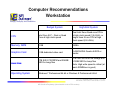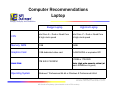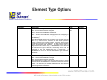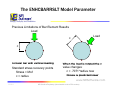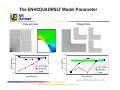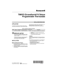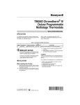
1
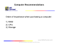
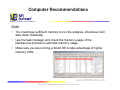
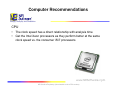
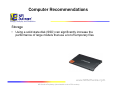
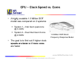
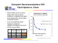
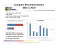
NEi Nastran Linear Tips and Tricks David Weinberg NEi Software Design, Analysis, and Simulation www.NEiSoftware.com NEi Sensitive/Proprietary (Not releasable to other FEA vendors) Design, Analysis, and Simulation NEi Nastran N t Basic B i Tips Ti and d Tricks Ti k www.NEiSoftware.com NEi Sensitive/Proprietary (Not releasable to other FEA vendors) Topics Design, Analysis, and Simulation • • • • • Selecting the Right System to Run On Element Type Options Improving Accuracy Assessing Accuracy Troubleshooting www.NEiSoftware.com NEi Sensitive/Proprietary (Not releasable to other FEA vendors) Design, Analysis, and Simulation Selecting the Right System to Run On www.NEiSoftware.com NEi Sensitive/Proprietary (Not releasable to other FEA vendors) Computer Recommendations Design, Analysis, and Simulation Order of Importance when purchasing a computer: 1) RAM 2) CPU 3) Storage www.NEiSoftware.com 6 NEi Sensitive/Proprietary (Not releasable to other FEA vendors) Computer Recommendations Design, Analysis, and Simulation RAM • You must have sufficient memory to run the analysis, otherwise it will slow down drastically • Use the task manager and check the memory usage of the Nastran.exe process to estimate memory usage • Make sure you are running a 64-bit OS to take advantage of higher memory limits www.NEiSoftware.com NEi Sensitive/Proprietary (Not releasable to other FEA vendors) Computer Recommendations Design, Analysis, and Simulation CPU • The clock speed has a direct relationship with analysis time • Get the Intel Xeon processors as they perform better at the same clock speed vs vs. the consumer i5/i7 processors www.NEiSoftware.com 8 NEi Sensitive/Proprietary (Not releasable to other FEA vendors) Computer Recommendations Design, Analysis, and Simulation Storage g • Using a solid state disk (SSD) can significantly increase the performance of large models that use a lot of temporary files www.NEiSoftware.com 9 NEi Sensitive/Proprietary (Not releasable to other FEA vendors) CPU – Clock Speed vs. Cores Design, Analysis, and Simulation • A highly scalable 1.3 Million DOF model was compared on 2 systems: System y 1 – Intel Xeon q quad-core @ 3.4GHz System 2 – Dual Intel Xeon 8-core @ 2.6GHz 1.3 Million DOF Direct Frequency Response Model • The goal is to find out if higher clock speeds are faster or if more cores are faster www.NEiSoftware.com NEi Sensitive/Proprietary (Not releasable to other FEA vendors) Computer Recommendations CPU Clock Speed vs. vs Cores Design, Analysis, and Simulation • If you do significant direct frequency response analysis, the larger core count CPUs may be faster # of CPUs 1 2 4 8 16 Solution Time Solution Time Solution Time Solution Time (4‐Core) (16‐Core) 1479 884 713 729 711 2234 1296 866 614 512 16‐Core % 16‐Core % Faster ‐34% ‐32% ‐18% 19% 39% Performance of 1 1.3M 3M DOF Direct Frequency Response 2500 2000 Solution T Time (sec) • Most models ((such as linear static) won’t see as much scaling so in general the higher clock speed CPU will be faster for typical models Solution Time (4-Core) 1500 Solution Time (16-Core) 1000 500 0 0 4 8 12 16 Number of CPUs www.NEiSoftware.com NEi Sensitive/Proprietary (Not releasable to other FEA vendors) Computer Recommendations SSD vs. HDD Design, Analysis, and Simulation CPU: Intel Core i7 @ 2.8GHz RAM: 8 GB HDD: Western Digital Black 7,200RPM 1TB SSD: Samsung 470 128GB With the SSD, an average speedup of 27% was found for large models that use a lot of temporary files www.NEiSoftware.com NEi Sensitive/Proprietary (Not releasable to other FEA vendors) Computer Recommendations Workstation Design, Analysis, and Simulation Budget System High-End System CPU Intel Core i5/i7 – Dual or Quad Core at high clock speed Dual Intel Xeon Quad-core CPUs at high clock speed (3.5+GHz). or single Xeon 8-core CPU at high clock speed (2 (2.8+GHz). 8+GHz) Memory, RAM 8 GB 32GB+ G hi C Graphics Card d 1 GB dedicated d di t d video id card d 2 GB NVIDIA Quadro K4000 or 2+GB similar Hard Disk 1TB SATA 7200RPM and 256GB SSD for temp p files Operating System Windows 7 Professional 64-bit or Windows 8 Professional 64-bit 2TB 7200 SATA for file storage and 512GB SSD for temp files Note: High write speed is critical (at least 400MB/sec is good) www.NEiSoftware.com NEi Sensitive/Proprietary (Not releasable to other FEA vendors) Computer Recommendations Laptop Design, Analysis, and Simulation Budget g Laptop p p High-End g Laptop p p CPU Intel Core i5 – Dual or Quad Core at high clock speed Intel Core i7 – Dual or Quad Core at high clock speed Memory, RAM 4 GB 16GB Graphics Card 1 GB dedicated video card 2+GB NVIDIA or equivalent ATI Hard Disk Operating System 1TB SATA 7200RPM 512GB or 1TB SSD. Note: High write speed is critical (at least 400MB/sec is good) Windows 7 Professional 64-bit or Windows 8 Professional 64-bit www.NEiSoftware.com NEi Sensitive/Proprietary (Not releasable to other FEA vendors) Design, Analysis, and Simulation Element Type Options www.NEiSoftware.com NEi Sensitive/Proprietary (Not releasable to other FEA vendors) Element Type Options Design, Analysis, and Simulation Parameter Description Type Default QUADELEMTYPE Quad element bending formulation option. SRI – Selective Reduced-Order Integration. DKQ – Discrete Kirchhoff-Mindlin Quadrilateral. DKT – Discrete Kirchhoff-Mindlin Triangle (either two overlapping or four dissecting DKT elements depending on the setting for QUADINODE). The DKT and DKQ elements may be slightly more accurate than the SRI in very coarse meshes; however, the SRI element performs better in nonlinear and buckling solutions. All three element types handle finite transverse shear stiffness. The SRI and DKQ element types are supported in all solutions. The DKT element type is supported t d in i lilinear solutions l ti only. l If QUADINODE is i sett to t ON and d the DKT element type is selected, the bending element will be comprised of four DKT subelements and a center node. If QUADINODE is set to OFF and the DKT element type is selected, the bending element will be comprised of two overlapping DKT sub elements. SRI/DKQ/ DKT SRI TRIELEMTYPE Tri element bending formulation option. DKT – Discrete Kirchhoff-Mindlin Triangle. SRI – Selective Reduced-Order Integration. The DKT element is typically more accurate than the SRI in coarse meshes and like the SRI element, works well for both thick and thin plates. Both element types handle finite transverse shear stiffness and are supported in all solutions. DKT/SRI DKT www.NEiSoftware.com NEi Sensitive/Proprietary (Not releasable to other FEA vendors) Element Type Options Design, Analysis, and Simulation Parameter Description Type Default HEXINODE Hex element internal node option. When set to ON, hex elements will produce more accurate results with a small performance degradation. The AUTO setting (default) will use the ON setting for stiffness matrix and stress calculations for models less than DECOMPAUTOSIZE or nonlinear solutions. For models greater than DECOMPAUTOSIZE and d AUTO AUTO, only l th the stiffness tiff matrix t i assembly bl phase h will ill use th the ON setting. The AUTO setting is recommended and provides optimal performance with accuracy. ON/OFF AUTO AUTO QUADINODE Quad element internal node option. When set to ON, quad elements will produce more accurate results with a small performance degradation. The AUTO setting (default) will use the ON setting for stiffness matrix and stress calculations for models less than DECOMPAUTOSIZE, models with composite shell elements, or nonlinear solutions. For models greater than DECOMPAUTOSIZE and AUTO, only the stiffness matrix assembly phase will use the ON setting. The AUTO setting provides optimal performance with accuracy. ON/OFF AUTO AUTO TETINODE Tet element internal node option. When set to ON, parabolic tet produce slightly g y more accurate results with a small elements will p performance degradation. The AUTO setting (default) will use the ON setting for stiffness matrix and stress calculations for models less than DECOMPAUTOSIZE or nonlinear solutions. For models greater than DECOMPAUTOSIZE and AUTO, only the stiffness matrix assembly phase will use the ON setting. ON/OFF AUTO OFF www.NEiSoftware.com NEi Sensitive/Proprietary (Not releasable to other FEA vendors) Element Type Options Design, Analysis, and Simulation Parameter Description Type Default SHELLRNODE Shell element drill degree of freedom option. When set to ON, CQUAD4 and CTRIA3 entries will be converted to CQUADR and CTRIAR entries, respectively. ON/OFF OFF www.NEiSoftware.com NEi Sensitive/Proprietary (Not releasable to other FEA vendors) Design, Analysis, and Simulation Improving Accuracy www.NEiSoftware.com NEi Sensitive/Proprietary (Not releasable to other FEA vendors) Improving Accuracy Design, Analysis, and Simulation • SKINGEN Model Parameter • ENHCBARRSLT Model Parameter • ENHCQUADRSLT Model Parameter www.NEiSoftware.com NEi Sensitive/Proprietary (Not releasable to other FEA vendors) The SKINGEN Model Parameter Design, Analysis, and Simulation • What a does it do do? Generates nonstructural surface skin elements over the exterior of the solid element part. • Wh Whatt are the th options? ti ? DISABLE, SURFACE, HYBRIDX, HYBRIDM, and HYBRIDA, see Reference Manual for more information. • Which options do I care about? Default which is DISABLE and the SURFACE option. • Wh When should h ld I use this thi parameter? t ? Anytime you have a solid model and are concerned about the coarseness of the mesh as it pertains to stress and strain accuracy. www.NEiSoftware.com NEi Sensitive/Proprietary (Not releasable to other FEA vendors) The SKINGEN Model Parameter Design, Analysis, and Simulation Automatic uto at c Su Surface ace S Skin Ge Generation e at o ((ASSG) SSG) • Creates nonstructural membrane surface elements on all solid element types to enhance the accuracy of peak stress recovery Solid Mesh Membrane Mesh www.NEiSoftware.com 7/3/2013 NEi Sensitive/Proprietary (Not releasable to other FEA vendors) The SKINGEN Model Parameter Design, Analysis, and Simulation We look at 2 different meshes: • • • A hex8 mesh and a tet10 mesh 1 element through the thickness C til Cantilever beam b with ith a b bending di lload d Tet10 mesh Hex8 mesh www.NEiSoftware.com NEi Sensitive/Proprietary (Not releasable to other FEA vendors) The SKINGEN Model Parameter Design, Analysis, and Simulation Theoretical solution • Z-displacement Pl 3 Pl δ= = 6.5 inches i h 3EI • Max bending stress Mc σ= = 28.8 KSI I www.NEiSoftware.com NEi Sensitive/Proprietary (Not releasable to other FEA vendors) The SKINGEN Model Parameter Design, Analysis, and Simulation Actual solution • Z-displacement Tet10 T t10 = 6 6.3 3 (2% error)) Hex8 = 6.4 (1% error) www.NEiSoftware.com NEi Sensitive/Proprietary (Not releasable to other FEA vendors) The SKINGEN Model Parameter Design, Analysis, and Simulation Actual solution – Element Actual solution – Skin • • Max bending stress Tet10 = 28.3/-28.3 28 3/ 28 3 (1% error) Hex8 = 30.7/-30.7 (10% error) Max bending stress Tet10 = 27 27.9/-28.3 9/ 28 3 (1% error) Hex8 = 27.5/-27.9 (2% error) www.NEiSoftware.com NEi Sensitive/Proprietary (Not releasable to other FEA vendors) The SKINGEN Model Parameter Design, Analysis, and Simulation More accurate outer fiber stress Von Mises Stress Mesh Convergence - Skin Stress vs. Solid Stress 250 245 240 235 230 225 220 215 210 Solid Stress Skin Stress Theoretical 0 1 2 3 4 5 6 7 Elements Through Thickness www.NEiSoftware.com 7/3/2013 NEi Sensitive/Proprietary (Not releasable to other FEA vendors) The SKINGEN Model Parameter Design, Analysis, and Simulation Solid element stress Shell skin element stress www.NEiSoftware.com NEi Sensitive/Proprietary (Not releasable to other FEA vendors) The SKINGEN Model Parameter Design, Analysis, and Simulation www.NEiSoftware.com NEi Sensitive/Proprietary (Not releasable to other FEA vendors) The ENHCBARRSLT Model Parameter Design, Analysis, and Simulation Previous Limitations of Bar Element Results Load Load c c Circular bar with vertical loading Standard stress recovery points Stress = Mc/I c = radius When the load is rotated the c value changes: c = .7071*radius now Stress is predicted lower www.NEiSoftware.com 7/3/2013 NEi Sensitive/Proprietary (Not releasable to other FEA vendors) The ENHCBARRSLT Model Parameter Design, Analysis, and Simulation • ENHCBARRSLT parameter addresses this Nastran limitation • Small FEA model of bar is built automatically and run with loading from forces/moments • Peak stress values extracted q are included • Shear stresses and torques • Requires PBARL or PBEAML www.NEiSoftware.com 7/3/2013 NEi Sensitive/Proprietary (Not releasable to other FEA vendors) The ENHCBARRSLT Model Parameter Design, Analysis, and Simulation Advantages: g • • • • No more stress recovery points needed Correct c value used Stresses now independent of recovery points Principal stresses reported which include full stress tensor www.NEiSoftware.com 7/3/2013 NEi Sensitive/Proprietary (Not releasable to other FEA vendors) The ENHCBARRSLT Model Parameter Design, Analysis, and Simulation New Output p Vector Definition: • • • • • SX-C = Maximum Stress SX-D = Minimum Stress SX E = Maximum Stress Magnitude SX-E SX-F = Minimum Stress Magnitude (usually zero unless SX-D is positive) SX MAX and SX-MAX d SX-MIN SX MIN are simply i l the th max and d min i off the th others th www.NEiSoftware.com 7/3/2013 NEi Sensitive/Proprietary (Not releasable to other FEA vendors) The ENHCBARRSLT Model Parameter Design, Analysis, and Simulation www.NEiSoftware.com 7/3/2013 NEi Sensitive/Proprietary (Not releasable to other FEA vendors) The ENHCBARRSLT Model Parameter Design, Analysis, and Simulation www.NEiSoftware.com 7/3/2013 NEi Sensitive/Proprietary (Not releasable to other FEA vendors) The ENHCQUADRSLT Model Parameter Design, Analysis, and Simulation Plate with Hole Filleted Plate 2500 550 Peak Stres ss [MPa] Peak Stre ess [MPa] 650 450 350 250 1 2 3 4 5 2250 2000 1750 1500 1 2 Mesh Refinement 3 4 5 Mesh Refinement www.NEiSoftware.com NEi Sensitive/Proprietary (Not releasable to other FEA vendors) The ENHCQUADRSLT Model Parameter Design, Analysis, and Simulation www.NEiSoftware.com 7/3/2013 NEi Sensitive/Proprietary (Not releasable to other FEA vendors) Design, Analysis, and Simulation Assessing Accuracy www.NEiSoftware.com NEi Sensitive/Proprietary (Not releasable to other FEA vendors) Results Quality Assessment Design, Analysis, and Simulation • Mesh Convergence Error • Solution Error Measure • Vector Resultant Balance www.NEiSoftware.com NEi Sensitive/Proprietary (Not releasable to other FEA vendors) Mesh Convergence Error Design, Analysis, and Simulation • • • • Establishes an upper bound of the stress error associated with shell and solid elements mesh density y Provides a normalized error based on von Mises stress at each solid or shell element g grid p point Useful in determining areas where mesh density should be increased or can be decreased Max/Min grid point and overall model shell and solid element p in all structural errors output solutions www.NEiSoftware.com NEi Sensitive/Proprietary (Not releasable to other FEA vendors) Mesh Convergence Error Design, Analysis, and Simulation www.NEiSoftware.com NEi Sensitive/Proprietary (Not releasable to other FEA vendors) Mesh Convergence Error Design, Analysis, and Simulation Output from .LOG and .RSF Files www.NEiSoftware.com NEi Sensitive/Proprietary (Not releasable to other FEA vendors) Mesh Convergence Error Design, Analysis, and Simulation www.NEiSoftware.com NEi Sensitive/Proprietary (Not releasable to other FEA vendors) Solution Error Measure - Epsilon Design, Analysis, and Simulation • Measure of accuracy of the global displacement vector • Values less than 10-6 are generally considered acceptable • The DELTASTRAINEGOUT model parameter can be used to output residual strain energy at each grid point • Causes for unacceptably large epsilon values discussed in next section www.NEiSoftware.com NEi Sensitive/Proprietary (Not releasable to other FEA vendors) Solution Error Measure - Epsilon Design, Analysis, and Simulation www.NEiSoftware.com NEi Sensitive/Proprietary (Not releasable to other FEA vendors) Solution Error Measure - Epsilon Design, Analysis, and Simulation Output from .LOG and .RSF Files www.NEiSoftware.com NEi Sensitive/Proprietary (Not releasable to other FEA vendors) Vector Resultant Balance Design, Analysis, and Simulation Output from .OUT File www.NEiSoftware.com NEi Sensitive/Proprietary (Not releasable to other FEA vendors) Design, Analysis, and Simulation Troubleshooting www.NEiSoftware.com NEi Sensitive/Proprietary (Not releasable to other FEA vendors) Typical Issues Design, Analysis, and Simulation Bad epsilon (greater that 10-6) Bad eigenvalue error measures (greater than 10-2) Bad eigenvalue orthogonality losses (greater than 10-2) Singularity or non-positive definite errors Element geometry warning messages More or less than expected number of rigid body modes Excessive mesh convergence error No convergence in the maximum number of iterations permitted • Applied load and SPC vector resultants are not equal and opposite pp • Unrealistic results • • • • • • • • www.NEiSoftware.com NEi Sensitive/Proprietary (Not releasable to other FEA vendors) Typical Issues Design, Analysis, and Simulation Bad epsilon (greater that 10-6) • Typically caused by a lack of constraint where the displacements are unrealistically high, often absurd • An A it iterative ti solution l ti was performed f d ffor th the solution l ti off displacements using the VIS or PCGLSS solver and convergence was not achieved or convergence tolerance too low (SPARSEITERTOL model parameter) • There are unrealistically high or low values of stiffness ((sometimes both)) in the model • Bad element geometry…use the ELEMGEOMOUT model parameter and check the .OUT file for a low or negative Jacobian www.NEiSoftware.com NEi Sensitive/Proprietary (Not releasable to other FEA vendors) Typical Issues Design, Analysis, and Simulation Bad epsilon (greater that 10-6) - Continued • Bad material properties…check the .OUT file material output • Check other warning messages and refer to User’s Manual E Error Messages M section ti www.NEiSoftware.com NEi Sensitive/Proprietary (Not releasable to other FEA vendors) Typical Issues Design, Analysis, and Simulation Bad eigenvalue error measures (greater than 10-2) • Causes and actions are similar to actions taken with a bad epsilon value • There Th are unrealistically li ti ll hi high h or llow values l off stiffness tiff (sometimes both) in the model • Unrealistically high values of mass • Check other warning messages and refer to User’s Manual Error Messages section www.NEiSoftware.com NEi Sensitive/Proprietary (Not releasable to other FEA vendors) Typical Issues Design, Analysis, and Simulation Bad eigenvalue orthogonality losses (greater than 10-2) • Causes and actions are similar to bad eigenvalue error measures www.NEiSoftware.com NEi Sensitive/Proprietary (Not releasable to other FEA vendors) Typical Issues Design, Analysis, and Simulation Singularity or non-positive non positive definite errors • Typically due to a lack of constraint or an internal mechanism in a static solution • Use U th the SOLUTIONERROR or NLKDIAGAFACT model d l parameters to help identify the source of the issue • Also can use RBCHECKLEVEL and RBCHECKMODES model parameters to identify the source • Negative stiffness can cause this so check the Grid Point Singularity Table and the .OUT file material output • Shell element drill DOF issues can cause this so try the SHELLRNODE model parameter www.NEiSoftware.com NEi Sensitive/Proprietary (Not releasable to other FEA vendors) Typical Issues Design, Analysis, and Simulation More or less than expected p number of rigid g body y modes • More means there is a lack of constraint or internal mechanisms • Less L means th there are iinternal t l constraints t i t either ith d due tto AUTOSPC by the solver or bad MPC equations, invalid RBE3 elements, or non-collocated CELASi elements www.NEiSoftware.com NEi Sensitive/Proprietary (Not releasable to other FEA vendors) Typical Issues Design, Analysis, and Simulation Element geometry warning messages • If the distortion is extreme such as a quad element that resembles a tri element or a tet element that is almost completely flat it can cause other issues and generate inaccurate results • The ELEMGEOMOUT model parameter will sort elements by worstt to t best b t making ki it easy to t verify if • Can use ALIGNEDGENODE model parameter if the issue is related to EPLR or EPAD • The AUTOFIXELEMGEOM model parameter will fix obvious issues like wrong node numbering www.NEiSoftware.com NEi Sensitive/Proprietary (Not releasable to other FEA vendors) Typical Issues Design, Analysis, and Simulation Excessive mesh convergence error • Often corrected by increasing the mesh density in that area if it is critical • Switching S it hi th the element l t ttype (parabolic ( b li vs. lilinear)) may h help l • Can also force QUADINODE and HEXINODE model parameters to ON www.NEiSoftware.com NEi Sensitive/Proprietary (Not releasable to other FEA vendors) Typical Issues Design, Analysis, and Simulation No convergence g in the maximum number of iterations p permitted • Typically this only happens if the user has limited the number of iterations as a performance consideration • Increasing I i th the maximum i number b off it iterations ti (f (for th the VIS and d PCGLSS solvers use MAXSPARSEITER model parameter) will fix this www.NEiSoftware.com NEi Sensitive/Proprietary (Not releasable to other FEA vendors) Typical Issues Design, Analysis, and Simulation Applied load and SPC vector resultants are not equal and opposite • Often due to the PCGLSS convergence tolerance being too high • Decreasing the convergence tolerance (use SPARSEITERTOL model parameter) will fix this • Could also be due to bad RBE3 element definition, invalid MPC equations, or internal constraints due to bad materials,, excessivelyy high g stiffnesses,, non-collocated CELASi elements, etc. www.NEiSoftware.com NEi Sensitive/Proprietary (Not releasable to other FEA vendors) Typical Issues Design, Analysis, and Simulation Unrealistic results • Check for other issues by first reviewing warning messages • Verify that previously discussed issues are not the cause • Use RBCHECKLEVEL model parameter and/or RBCHECKMODES • Check the .OUT file material output • Check Grid Point Weight Generator output • Use PARMASSOUT model parameter to verify individual part mass and d di dimensions i • Review vector resultants in .OUT file www.NEiSoftware.com NEi Sensitive/Proprietary (Not releasable to other FEA vendors) Useful Parameters for Troubleshooting Design, Analysis, and Simulation Parameter Description Type Default AUTOFIXELEMGEOM Option for automatically correcting elements that are singular due to an incorrect ordering of the element grid points. ON/OFF ON AUTOFIXRIGIDELEM When set to ON, will automatically correct improperly defined RBE3 elements by adding rotational degrees of freedom to averaging grid points po ts as needed eeded to p prevent e e t rigid g d body motion. ot o ON/OFF ON AUTOFIXRIGIDSPC When set to ON, will automatically correct the following rigid element, interpolation element, and MPC equation issues by adding a near rigid spring at the dependent degrees of freedom: ON/OFF OFF • A rigid element, interpolation element, or MPC equation dependent degree of freedom is constrained. • One or more rigid g elements,, interpolation p elements,, or MPC equations reference the same dependent degree of freedom. • A series of rigid elements, interpolation elements, and/or MPC equations are connected in a continuous link. • An RBE2 element is defined with the independent grid point located at the origin of a cylindrical coordinate system and rigidity is desired only in the R or T component direction. When AUTOFIXRIGIDSPC is set to OFF, OFF behavior will be that of a rigid element defined in the Cartesian rectangular system which defined the specified cylindrical system. When AUTOFIXRIGIDSPC is set to ON and a translational or rotational component is missing, the local grid coordinate system at each independent grid point defines that dependent/independent segment. The spring element stiffness is defined by the KRIGIDELEM model parameter See KRIGIDELEM below. parameter. below www.NEiSoftware.com NEi Sensitive/Proprietary (Not releasable to other FEA vendors) Useful Parameters for Troubleshooting Design, Analysis, and Simulation Parameter Description Type ELEMGEOMOUT Option to output individual element geometry statistics. When ELEMGEOMOUT is set to ON, the following statistics are output to the Model Results Output File for each element: ON/OFF OFF ASPECTRATIO/ SKEWANGLE/ JACOBIAN1/ O JACOBIAN2 • Aspect ratio • Taper ratio • Skew angle • Warping angle Default • Normalized Jacobian The data is sorted based on normalized Jacobian determinant, skew g , and aspect p ratio in ascending g order for each element type. yp If angle, ELEMGEOMOUT is set to ASPECTRATIO, then the sort will be in descending order and only based on element aspect ratio. If ELEMGEOMOUT is set to SKEWANGLE, then the sort will be in descending order and only based on element skew angle. If ELEMGEOMOUT is set to JACOBIAN1, then the sort will be in ascending order and only based on the total Jacobian determinant normalized using element volume. If ELEMGEOMOUT is set to JACOBIAN2 then the sort will be in ascending order and only based JACOBIAN2, on the minimum Jacobian determinant at each corner node normalized using adjacent element edge lengths. www.NEiSoftware.com NEi Sensitive/Proprietary (Not releasable to other FEA vendors) Useful Parameters for Troubleshooting Design, Analysis, and Simulation Parameter Description Type Default PARTGEOMOUT Individual part geometry statistics output option. When set to ON, additional part statistical information will be output including: ON/OFF OFF ON/OFF OFF PARTMASSOUT • Material • Property p y type yp • Bounding box dimensions • Mass • Volume • Number of grid points • Number of elements Individual part mass properties output option. When set to ON, additional part mass properties information will be output including: • Material • Property type • Mass • Location of center of gravity • Mass moment of inertia www.NEiSoftware.com NEi Sensitive/Proprietary (Not releasable to other FEA vendors) Useful Parameters for Troubleshooting Design, Analysis, and Simulation Parameter Description Type Default NLKIAGAFACT Specifies the stiffness to be added to diagonal terms of the global stiffness matrix. Specifying a small positive value is useful in stabilizing a solution and preventing a non-positive definite or singularity error. In nonlinear static solutions the added stiffness is decreased at the completion of each increment so to reach the value defined by NLKDIAGMINAFACT at the completion of the last increment. See also NLKDIAGCOMP and NLKDIAGMINAFACT. Real 0.0 SOLUTIONERROR When set to ON, it directs the program to substitute the value of FACTDIAG (default = 1.0E-10) for the factored diagonal term when a singularity or non-positive definite is detected. If FACTDIAG is set to zero, non-positive definites are ignored, while a singularity will result in program termination termination. SOLUTIONERROR and FACTDIAG are ignored in eigenvalue solutions and when the sparse iterative solvers (PCGLSS or VIS) are used. While this option is useful for modeling checkout, it may lead to solutions of poor quality or fatal messages later in the run. It is recommended that SOLUTIONERROR be set to OFF for production runs. ON/OFF OFF www.NEiSoftware.com NEi Sensitive/Proprietary (Not releasable to other FEA vendors) Useful Parameters for Troubleshooting Design, Analysis, and Simulation Parameter Description Type Default RBCHECKLEVEL Stiffness matrix equilibrium checks option. Equilibrium checks verify whether an unrestrained model can undergo simple rigid body motion without generating internal forces. There are six options: 0 – Do not perform any checks. 1 – Perform checks after stiffness matrix assembly before multipoint constraints are applied. 2 – Perform checks after multipoint constraints are applied before single point constraints are applied. 3 – Perform checks after single point constraints are applied before static condensation. 4 – Perform checks after static condensation before decomposition. decomposition 5 – Perform checks 1 – 4 above. 0 ≤ Integer ≤ 5 0 RBCHECKMODES Specifies the number of modes to solve for in an automated modal rigid body check. When set to a value greater than zero will perform an eigenvalue extraction analysis requesting that number of specified modes on the unconstrained model. Displacements and strain energy are output. Multipoint constraints requested in the first subcase of the model will be included. Integer ≥ 0 0 www.NEiSoftware.com NEi Sensitive/Proprietary (Not releasable to other FEA vendors) Design, Analysis, and Simulation www.NEiSoftware.com NEi Sensitive/Proprietary (Not releasable to other FEA vendors) Design, Analysis, and Simulation Questions www.NEiSoftware.com NEi Sensitive/Proprietary (Not releasable to other FEA vendors)