1
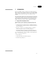
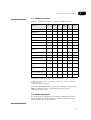
user manual
BioProcess HPLC Columns
BioProcess HPLC Columns
Instructions for Use
um 56-3225-40 AB
Important user information
All users must read this entire manual to fully
understand the safe use of the BioProcess HPLC
columns.
CE Certification
This product meets all requirements of applicable
CE directives. A copy of the corresponding
declaration of conformity is available on request.
The CE symbol and corresponding declaration of
conformity is valid for the instrument when it is:
-
used as a stand-alone unit, or
-
connected to other CE-marked Amersham
Biosciences instruments, or
-
connected to other products recommended or
described in this manual, and
-
used in the same state as it was delivered from
Amersham Biosciences, except for alterations
described in this manual.
Terms and Conditions of Sale
Unless otherwise agreed in writing, all goods and
services are sold subject to the terms and conditions
of sale of the company within the Amersham
Biosciences group that supplies them. A copy of
these terms and conditions is available on request.
Should you have any comments on this product, we
will be pleased to receive them at:
Amersham Biosciences AB
SE-751 84 Uppsala
Sweden
Trademarks
BioProcess and Drop Design are trademarks of
Amersham Biosciences Limited. Amersham and
Amersham Biosciences are trademarks of
Amersham plc. Triton is a trademark of Union
Carbide Chemicals and Plastic Company Inc.
Office Addresses
Amersham Biosciences AB
SE-751 84 Uppsala
Sweden
Amersham Biosciences UK Limited
Amersham Place
Little Chalfont
Buckinghamshire
England HP7 9NA
Amersham Biosciences Corp
800 Centennial Avenue
PO Box 1327
Piscataway NJ 08855
USA
Amersham Biosciences Europe GmbH
Munzinger Strasse 9
D-79111 Freiburg
Germany
Amersham Biosciences K.K.
Sanken Building
3-25-1 Hyakunincho, Shinjuku-ku
Tokyo 169-0073
Japan
Amersham Biosciences China Limited
13/F., Tower I
Ever Gain Plaza
88 Container Port Road
Kwai Chung, New Territories
Hong Kong
© Copyright Amersham Biosciences AB - 2003
All rights reserved
Safety Notices
This Instructions for Use contains safety notices prompting you on
correct use of the column to avoid personal injury and/or damage of the
equipment, or to present information that can optimize your use of the
columns. The various types of safety notice include:
Warning notices
WARNING! The Warning notice highlights instructions that must be
strictly followed in order to avoid personal injury. Do not proceed
until the instructions are clearly understood and all stated conditions
are met.
Caution notices
CAUTION! The Caution notice highlights instructions or conditions
that must be followed to avoid damage to the product or to other
equipment. Do not proceed until the instructions are clearly
understood and all stated conditions are met.
Important notices
IMPORTANT! The Important notice highlights instructions or
details relating to instructions that will help ensure optimal use of the
column.
Notes
Note: Notes are used to indicate additional tips and information for troublefree and optimal use of the product.
Contents
1 Introduction
1.1 Scope of this Instructions for Use . . . . . . . . . . . . . . . . . . . . . 1
1.2 Approved operators . . . . . . . . . . . . . . . . . . . . . . . . . . . . . . . 2
1.3 Intended use of the columns . . . . . . . . . . . . . . . . . . . . . . . . . 2
1.4 Safety precautions . . . . . . . . . . . . . . . . . . . . . . . . . . . . . . . . 2
1.5 Labelling of the column . . . . . . . . . . . . . . . . . . . . . . . . . . . . 3
2 Specifications and characteristics
2.1 Primary specifications . . . . . . . . . . . . . . . . . . . . . . . . . . . . . 5
2.2 Materials . . . . . . . . . . . . . . . . . . . . . . . . . . . . . . . . . . . . . . . 5
2.3 Chemical resistance. . . . . . . . . . . . . . . . . . . . . . . . . . . . . . . 6
2.4 Column bed heights . . . . . . . . . . . . . . . . . . . . . . . . . . . . . . . 6
3 Installing the column
3.1 Removing the column from its packaging. . . . . . . . . . . . . . . . 7
3.2 Connecting the column tube to the frame. . . . . . . . . . . . . . . . 7
3.3 Identifying the column components . . . . . . . . . . . . . . . . . . . . 7
3.4 Column connections . . . . . . . . . . . . . . . . . . . . . . . . . . . . . . . 8
3.5 Filling the compression fluid tank . . . . . . . . . . . . . . . . . . . . . 8
3.6 Surface cleaning . . . . . . . . . . . . . . . . . . . . . . . . . . . . . . . . . 8
4 Operation
4.1 Calculating the amount of medium needed. . . . . . . . . . . . . . . 9
4.2 Preparing the slurry . . . . . . . . . . . . . . . . . . . . . . . . . . . . . . . 9
4.3 Filling the column. . . . . . . . . . . . . . . . . . . . . . . . . . . . . . . . 10
4.4 Packing the medium. . . . . . . . . . . . . . . . . . . . . . . . . . . . . . 11
4.5 Performing a run . . . . . . . . . . . . . . . . . . . . . . . . . . . . . . . . 12
4.6 Unpacking the medium from the column . . . . . . . . . . . . . . . 12
4.7 Cleaning-in-Place (CIP) . . . . . . . . . . . . . . . . . . . . . . . . . . . 13
4.8 Storage . . . . . . . . . . . . . . . . . . . . . . . . . . . . . . . . . . . . . . . 13
Introduction
1
Introduction
BioProcessTM HPLC columns are stainless steel columns designed for
use in scale up chromatographic separations in a sanitary environment.
HPLC columns can be operated in conditions of up to 100 bar. HPLC
columns are fully scalable in the ranges 50 to 1000 mm column
diameter.
The columns feature dynamic axial compression that uses solvent as the
compression fluid. Together with a specially designed flow distribution
system fitted at both the top and bottom of the column, this ensures a
uniform distribution of the mobile phase across the whole bed. An
adapter, in the form of a piston, is used to regulate the bed height.
1.1 Scope of this Instructions for Use
This Instructions for Use is designed as a general introduction and
guide to column operation. Specifically, the Instructions will cover:
• Column specifications and characteristics, including information
on column function, column specifications, materials and chemical
resistance (Chapter 2).
• Preparing a column for use, including installation, assembly of
column components, and pre-run cleaning (Chapter 3).
• Operation, including some suggested recommended methods for
column filling, packing, unpacking, CIP, and storage (Chapter 4).
An accompanying manual, “BioProcess HPLC Columns Maintenance
Guide”, covers the following topics:
• Safety (Chapter 1).
• Column disassembly and assembly (Chapter 2).
• Troubleshooting (Chapter 3).
• p1
1
Introduction
1.2 Approved operators
To be able to use the BioProcess HPLC columns, you must have read,
understood and be acquainted with the Instructions for Use. However,
this does not guarantee user safety - it is the responsibility of the user’s
company to ensure safe operation and training. Training courses are
available and can be arranged by contacting your local Amersham
Biosciences representative.
1.3 Intended use of the columns
BioProcess HPLC columns are designed for production scale
separations.
IMPORTANT! BioProcess HPLC columns are specified to operate at
pressures (defined as the pressure in excess of ambient [1 bar]) up to
100 bar, and consequently the local authorities may consider them to
be pressure vessels. Users of the columns are responsible for ensuring
that the columns are installed and handled in accordance with the
local regulations.
1.4 Safety precautions
Information given in this Instructions for Use is suggested best working
practice and shall in no way take precedence over individual
responsibilities or local regulations. Great effort has been placed on the
design and manufacture of the various parts of the equipment so that it
will comply with all applicable safety aspects for this type of
equipment. During the operation and during other work with a
pressurized vessel, it is always each individual's responsibility to
consider:
• Their own and others' personal safety.
• The safety of the equipment through correct use in accordance with
the descriptions and instructions given in this Instructions for Use.
WARNING! Always use protective clothing appropriate with current
application to ensure personal safety during operation.
WARNING! Pay extra attention when moving the adapter as there is
a risk for trapping your hands.
WARNING! Do not exceed the rated pressure of the incoming air
supply, otherwise there is a risk of personal injury and damage to the
instrumentation.
• p2
1
Introduction
IMPORTANT! Whenever a BioProcess HPLC column is used,
always keep the Instructions for Use on hand.
IMPORTANT! The end user must ensure that all installation,
maintenance, operation and inspection is carried out by qualified
personnel who are adequately trained and understand the operating
instructions.
1.5 Labelling of the column
The BioProcess HPLC columns are labelled as follows:
Fig 1-1. The BioProcess HPLC column rating plate.
• p3
1
Specifications and characteristics
2
Specifications and characteristics
BioProcess HPLC columns feature hydraulic movement of the adapter
to pack the medium. This is achieved using the in-built packing station
on the column frame. A pump located in the base of the frame uses
compressed air to push compression fluid (ethanol) from a storage tank
into the hydraulic chamber of the column and thereby push the adapter
upwards to pack the medium.
Lid mobile phase
Lid
Adsorbent
Adapter
Compression fluid
Pressure outlet
Base end plate
Air inlet
Adapter rod
Adapter mobile phase
Compression fluid tubing
Compression fluid tank
Pump
Fig 2-1. General construction of a BioProcess HPLC column.
BioProcess HPLC columns comply with the technical performance 100
bar in industrial BioProcessing. In addition, they withstand
temperatures up to 50 °C. Construction is in stainless steel AISI 316 L,
and the sanitary design includes Quick Connections. Sealing materials
are resistant to organic solvents and a leakage detection system is
included. Table 2-1 gives the primary specifications of selected
columns. Table 2-2 lists the materials of the main column components,
and Table 2-3 the chemical resistance.
• p4
2
Specifications and characteristics
2.1 Primary specifications
Table 2-1 Properties of selected BioProcess HPLC columns.
Designation
Size DxL
(mm)
CrossMax.
sectional column
area
vol. (L)
(cm2)
Overall
Dry
column ht.
weight
(mm) - adapter (kg)
in top pos.
HPLC 50/700
50x700
19.6
1.4
2100
100
HPLC 75/700
75x700
44.2
3.1
2100
150
HPLC 100/700
100x700
78.5
5.5
2200
200
HPLC 150/700
150x700
176.7
12.4
2200
250
HPLC 200/700
200x700
314.2
22.0
2200
300
HPLC 250/700
250x700
490.9
34.4
2200
375
HPLC 300/700
300x700
706.8
49.5
2400
475
HPLC 450/700
450x700
1590.0
111.3
2800
650
HPLC 600/700
600x700
2827.4
197.9
2800
1000
2.2 Materials
Table 2-2. Materials of main components.
Component
Material
In contact
Column tube
Stainless steel 316 L
Yes
Base end plate (‘Top’)*
Stainless steel 316 L
No
Adapter and adapter rod
Stainless steel 316 L
Yes
Distributor
PE or Stainless steel 316 L
Yes
Lid (‘Bottom’)*
Stainless steel 316 L
Yes
Net
Stainless steel 316 L
Yes
Sealings
FEP encapsulated Viton, PTFE, PE
Yes
Valves
Stainless steel 316 L
Yes
PE = polyethylene, FEP = fluoroethenepropene, PTFE = polytetrafluoroethene.
* For maintenance purposes and ordering of spare parts the HPLC columns are
labelled in the upright position, that is with the adapter pushing down into the
column. This orientation is used for designating top and bottom of the column.
However, the HPLC columns are packed and run in the inverted upright
position, that is with the adapter pushing upwards into the column. Thus the
‘top’ and ‘bottom’ labels also become inverted. The end plates are thus referred
to as the ‘lid’ and ‘base end plate’ according figure 2-1.
• p5
2
Specifications and characteristics
2.3 Chemical resistance
Table 2-3. Chemical resistance of BioProcess HPLC columns
Chemical
SS 316L EPDM
FEP
PEEK
450 G
PE
PTFE
Acetic acid 1.7 M
+
+
+
+
+
+
EtOH 20%
+
+
+
+
+
+
EtOH 40%
+
+
+
+
(+)
+
Ethylene glycol 50%
+
+
+
+
+
+
Formaldehyde 1.7 M
+
+
+
+
+
+
Formic acid 10%
+
+
+
+
+
+
Glycerol 100%
+
+
+
+
+
+
Hydrochloric acid
0.1 M
-
+
+
+
+
+
Isopropyl alcohol 30% +
+
+
+
(+)
+
Nitric acid 0.1 M
+
+
+
+
(+)
+
Phosphoric acid 25%
(+)
+
+
+
+
+
Sodium chloride 0.5 M + 1)
+
+
+
+
+
Sodium hydroxide
2 M 2)
+
+
+
+
+
+
Trifluoroacetic acid
0.1%
+
+
+
+
+
+
Triton™ X-100 100% +
+
+
+
+
+
UREA 8 M
+
+
+
+
+
+
+ Resistant (+) Limited resistance - Not recommended
1) NaCl can cause corrosion on stainless steel at pH <5. Do not use NaCl in
storage solutions.
2) Maximum exposure 4 hours.
SS=stainless steel, EPDM=ethylene propylene diene, FEP=fluoroethenepropene,
PEEK=polyetherether ketone, PE=polyethylene, PP=polypropylene,
PTFE=polytetrafluoroethene.
2.4 Column bed heights
To calculate the bed height in your particular column, please refer to
the documentation supplied with your column or contact your local
Amersham Biosciences representative.
• p6
2
Installing the column
3
Installing the column
3.1 Removing the column from its packaging
Place the transport box on an even foundation and remove the side that
has been fastened with screws. Roll out the column frame on its wheels.
IMPORTANT! Make sure that the column is placed on an even
foundation.
3.2 Connecting the column tube to the frame
Unpack the column tube and fix it to the frame using the bracket on the
frame. For the 50 mm diameter column, make the attachment halfway
along the column tube length. The BioProcess HPLC column is now
ready for installation and use.
3.3 Identifying the column components
The columns are supplied together with mobile phase and compression
valves, and a frame-mounted packing station that includes pump,
safety valve, pressure gauges, valves and a regulator (see figure 3-1).
G. Lid mobile phase
valve
H. Column tube
I. Fixture device
A. Hydraulic
chamber valve
B. Compression
fluid tank
C. Adapter rod with
(D.) adapter mobile
phase connection
E. Air pressure
regulator
F. Compression
pump
J. Air pressure
K. Column pressure
L. Tubing for
compression
M. Air valve
N. Air Connection
O. Hydraulic flow
direction switches
Fig 3-1. Schematic diagram of a BioProcess HPLC column
• p7
3
Installing the column
3.4 Column connections
Compressed air is connected to the AIR CONN connection (N), which
is used by the pump (F) to push compression fluid from the
compression fluid tank (B) into the hydraulic chamber of the column
via the compression tubing (L).
Feedstock can be applied either upflow or downflow via the adapter
mobile phase connection (D) or lid mobile phase valve (G), respectively.
The lid mobile phase valve (G) is a 2 way, three port valve.
3.5 Filling the compression fluid tank
Prior to a run, fill the compression fluid tank with ethanol (suitable
concentration to inhibit microbial contamination). There is a cap for
filling purposes on the frame of the stand. The level of the compression
fluid can be seen by the indicator on the frame.
3.6 Surface cleaning
Amersham Biosciences recommends that you clean the outside of the
column with, for example warm water and/or 20%(v/v) ethanol to
remove any surface residues acquired during removal from the
packaging.
• p8
3
Operation
4
Operation
IMPORTANT! Various methods are available for operating the
BioProcess HPLC columns.
The procedure presented in this chapter describes preparing the
column for a run upflow.
For specific information on the best methods to meet your needs
please contact your Amersham Biosciences representative.
4.1 Calculating the amount of medium needed
The compression factor of the medium can be calculated by dividing
the settled volume of the medium by the desired packed volume of the
medium. The compression factor is anywhere between 1.15 and 1.30
and depends on the specific medium being used. Please check the
Instructions supplied with the medium that you are using.
4.2 Preparing the slurry
To prepare the medium a slurry-unit is recommended, which consists
of a suspension tank with a mixing device, decanting pipe and a slurry
pump.
Note: A slurry unit for your BioProcess HPLC column can be ordered from
Amersham Biosciences. Please contact your local Amersham
Biosciences representative.
• p9
4
Operation
4.3 Filling the column
G. Lid mobile phase
valve
H. Column tube
I. Fixture device
A. Hydraulic
chamber valve
B. Compression
fluid tank
C. Adapter rod with
(D.) adapter mobile
phase connection
E. Air pressure
regulator
F. Compression
pump
J. Air pressure
K. Column pressure
L. Tubing for
compression
M. Air valve
N. Air Connection
O. Hydraulic flow
direction switches
Fig 4-1. Schematic diagram of Bioprocess HPLC column.
The following section assumes that the column is empty and shall be
packed with fresh medium. If however the column needs first to be
emptied please see 4.6“Unpacking the medium from the column” on
page 12.
1. Remove the lid on the column tube:
Lock the column in its inverted upright position as shown in figure
4-1.
Loosen and remove the bolts connecting the lid to the column tube.
The lid may then be removed using a suitable hoist or crane.
Note: To help remove the lid you may need to insert T-shaped jacking bolts
into threaded holes on the lid. Screwing these in will help to release the
lid.
• p10
4
Operation
2. Withdraw the adapter to its most extreme position:
Set both of the hydraulic flow direction switches (O) to the FROM
COLUMN position.
CAUTION! Both hydraulic flow direction switches (O) must be
moved to the same position before starting the pump. A high
pressure can build up inside the tubing from the pump if the left
switch is set to TO COLUMN and the right switch to FROM
COLUMN.
Set the AIR ON/OFF switch (M) to ON and use the air pressure
regulator (E) to set the air pressure (J) to an appropriate pressure
(e.g. 0.5 bar for 50 mm diameter columns).
The adapter will move out of the column by itself.
When the adapter is fully extended turn off the air pump (M).
3. Gently swirl the slurry an extra time and pour the appropriate
amount into the open end of the column tube.
4. Replace the lid using the bolts.
4.4 Packing the medium
1. Direct the outlet valve (G) to the waste port.
2. Start the compression:
Set both of the hydraulic flow direction switches (O) to the TO
COLUMN position.
CAUTION! Both hydraulic flow direction switches (O) must be
moved to the same position before starting the pump. A high
pressure can build up inside the tubing from the pump if the left
switch is set to TO COLUMN and the right switch to FROM
COLUMN.
Set the AIR ON/OFF switch (M) to ON and use the air pressure
regulator (E) to set the air pressure (J) and thereby raise the
hydraulic pressure (K) to achieve your target volume.
IMPORTANT! Begin packing with a lower hydraulic pressure, for
example 20 bar.
• p11
4
Operation
The adapter moves into the column tube driven by the compression fluid. Fluid from the slurry is pushed out of the outlet valve
(G) as the bed is compressed and packed. Packing continues until
no more drops of fluid come from the waste pipe connected to the
outlet valve (G).
3. Adjust the column pressure (K) to the final pressure using the air
pressure regulator. Keep the pump running to maintain the
packing.
4.5 Performing a run
For the procedure described here, feedstock is entered into the bed via
the adapter mobile phase (D) through the shaft of the adapter rod (C).
An upwards flow is created and fluid exits the bed through the lid
mobile phase valve (G), where it can then be directed to one of two
ports from the valve.
Perform a run according to you own procedures. Contact you local
Amersham Biosciences representative for further advice and
information.
4.6 Unpacking the medium from the column
After you have completed your run(s) and wish to unpack the medium
first perform a CIP procedure (see 4.7“Cleaning-in-Place (CIP)” on
page 13). To unpack the column:
1. Turn off the pump pressure with the regulator (E).
2. Release residual pressure in the column tube by opening the
hydraulic chamber valve (A). Collect the hydraulic fluid in a
suitable container.
3. Remove the lid on the column tube:
Lock the column in its inverted upright position as shown in figure
4-1.
Loosen and remove the bolts connecting the lid to the column tube.
The lid may then be removed using a suitable hoist or crane.
Note: To help remove the lid you may need to insert T-shaped jacking screws
into threaded holes on the lid. Screwing these in will help to release the
lid.
4. Invert the column 180 degrees so that the pellet can later be easily
collected in a container.
5. Set the hydraulic flow direction switches (O) to the TO COLUMN
position.
• p12
4
Operation
CAUTION! Both hydraulic flow direction switches (O) must be
moved to the same position before starting the pump. A high
pressure can build up inside the tubing from the pump if the left
switch is set to TO COLUMN and the right switch to FROM
COLUMN.
Set the AIR ON/OFF switch (M) to ON and use the air pressure
regulator (E) to set the air pressure (J) to an appropriate level to
push the adapter.
As the adapter moves further into the column tube it pushes out
the packed medium pellet. Catch the medium pellet in a suitable
container.
6. Turn off the air pump (M).
7. Clean the adapter, lower bed support on the adapter, and the
opening of the column tube with ethanol or other suitable cleaning
agent and lint-free tissue paper.
8. Return the adapter to its extended position (see 4.3“Filling the
column” on page 10, step 2)
4.7 Cleaning-in-Place (CIP)
You are recommended to use a CIP method suitable for the procedure
and medium that you are using. Please contact your local Amersham
Biosciences representative for advice.
4.8 Storage
With the packed medium in the column, pump in an upward direction
at least 2-5 sedimented bed volumes of 20% ethanol and/or 10 mM
NaOH or other appropriate solution, at a flow rate of 100 cm/h. Seal
the column valves and store the column at room temperature.
• p13
4