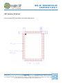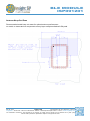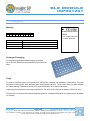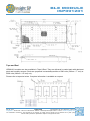
1
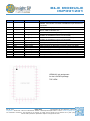
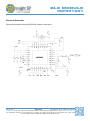
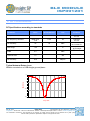
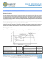
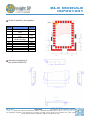
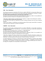
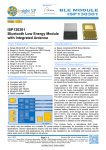
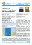
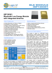
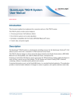
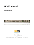
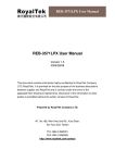
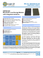
BLE MODULE ISP091201 ISP091201 Bluetooth Low Energy Module with Integrated Antenna Key Features Single Mode BLE v4.0 Slave Nordic Semiconductor µBlue products based Includes transceiver, baseband, software stack Ultra Low Power Consumption Single 1.9 to 3.6 V supply Very small size 8.0 x 12.0 x 1.5 mm Temperature -40 to 85 °C Fully integrated RF matching and Antenna Integrated 16 MHz Crystal Clock Certifications FCC Limited Modular Certification Complies with CE Complies with IC Bluetooth SIG certified RoHS compliant Applications Space constrained BLE Slave Devices Sport and fitness sensors Health care sensors Out of Range (OOR) sensors Personal User Interface Devices (PUID) Remote controls General Description This module is based on Nordic Semiconductor nRF8001 µBlue Bluetooth Low Energy Platform. The nRF8001 is a single chip transceiver with an embedded baseband protocol engine, suitable for ultra low power wireless applications conforming to the Bluetooth Low Energy Specification contained within v4.0 of the overall Bluetooth specification. The nRF8001, used in the current revision of ISP091201, is a production product using a RoM for the baseband protocol engine. The µBlue transceiver is specifically designed for both PC peripherals and ultra low power applications such as sports and wellness sensors. For sensor applications, the ultra low power consumption and advanced power management enables battery lifetimes up to several years on a coin cell battery. The ISP091201 module size measures 8 x 12 x 1.5 mm. The module integrates all the decoupling capacitors, the 16 MHz crystal and load capacitors plus the RF matching circuit and antenna in addition to the transceiver. As the module has several end applications, the antenna was designed to be compatible with several ground plane sizes including that of a USB dongle and a cell phone. The module can operate as a standalone Bluetooth sensor node with the addition of a transducer, a small external microprocessor to run application software, a 32 kHz crystal and a DC power source. May 29, 2015 Document Ref: isp_ble_DS091201_R19.docx Page 1/18 Insight SiP – Green Side – 400 avenue Roumanille – BP 309 – 06906 Sophia-Antipolis Cedex – France – www.insightsip.com The information contained in this document is the property of Insight SiP and should not be disclosed to any third party without written permission. Specification subject to change without notice. BLE MODULE ISP091201 Contents 1. Electrical Specifications ...............................................................................................................Page 2 2. RF Performances ........................................................................................................................Page 5 3. Product Development Tools ........................................................................................................Page 8 4. Mechanical Outlines ....................................................................................................................Page 9 5. Packaging .................................................................................................................................Page 12 6. Storage & Soldering Information ................................................................................................Page 14 7. Quality & User Information.........................................................................................................Page 15 1. Electrical Specifications Electrical Performance Temperature range -40 to +85 °C Parameter Value Unit 1.9 V Peak current, receiver active 14.6 mA Peak current, transmitter active 12.7 mA Current drain, connection-less state 0.5 µA 2 µA Supply voltage Min. Supply Voltage Current consumption Static levels Current drain between connection events Pin Assignment Pin 1–5 6 Name NC OUT_ANT Pin function Not Connected Antenna In/Out 7 OUT_MOD Module In/Out 8 9 10 GND NC MOSI Ground Not Connected Digital input Description Isolated pad on application PCB for mechanical stability This pin is connected to the internal antenna. It should be connected to Pin 7 OUT_MOD for normal operation. During certification the pin may be connected to an RF connector for antenna measurement This pin is the RF I/O pin of the BLE module. It should be connected to Pin 6 OUT_ANT for normal operation. During certification the pin may be connected to an RF connector for module measurement using a Bluetooth test setup Should be connected to ground plane on application PCB Isolated pad on application PCB for mechanical stability ACI Master Out Slave In May 29, 2015 Document Ref: isp_ble_DS091201_R19.docx Page 2/18 Insight SiP – Green Side – 400 avenue Roumanille – BP 309 – 06906 Sophia-Antipolis Cedex – France – www.insightsip.com The information contained in this document is the property of Insight SiP and should not be disclosed to any third party without written permission. Specification subject to change without notice. BLE MODULE ISP091201 Pin 11 Name DCC Pin function PWM driver 12 13 AVDD VCC_nRF Power Power 14 15 GND XL2 Ground Analog output 16 XL1 Analog output 17 18 19 20 21 22 23 24 25 26-36 ACTIVE TXD SCK RXD REQN MISO GND RDYN RESET NC Digital output Digital output Digital input Digital output Digital input Digital output Ground Digital output Digital Input Not Connected Description PWM driver for the external LC filter if the DC/DC converter is enabled. If the DC/DC converter is disabled this pin shall be not connected Analog power supply (1.9 – 3.6V DC) Power supply (1.9 – 3.6V) Supplies the DC/DC converter and GPIOs. VDD in nRF8001 doc Should be connected to ground plane on application PCB Connect to external 32.768kHz crystal oscillator (if internal RC oscillator is enabled then leave not connected) Connect to external 32.768kHz crystal oscillator (if internal RC oscillator is enabled then leave not connected) Device RF front end activity indicator UART (transmit) for Bluetooth low energy Direct Test Mode ACI clock input UART (receive) for Bluetooth low energy Direct Test Mode ACI request pin (handshaking, active low) ACI Master In Slave Out Should be connected to ground plane on application PCB ACI device ready indication (handshaking) Reset (Active Low) Isolated pad on PCB for mechanical stability ISP091201 pin assignment for the LGA QFN package TOP VIEW May 29, 2015 Document Ref: isp_ble_DS091201_R19.docx Page 3/18 Insight SiP – Green Side – 400 avenue Roumanille – BP 309 – 06906 Sophia-Antipolis Cedex – France – www.insightsip.com The information contained in this document is the property of Insight SiP and should not be disclosed to any third party without written permission. Specification subject to change without notice. BLE MODULE ISP091201 Electrical Schematic Electrical schematic showing ISP091201 module connections May 29, 2015 Document Ref: isp_ble_DS091201_R19.docx Page 4/18 Insight SiP – Green Side – 400 avenue Roumanille – BP 309 – 06906 Sophia-Antipolis Cedex – France – www.insightsip.com The information contained in this document is the property of Insight SiP and should not be disclosed to any third party without written permission. Specification subject to change without notice. BLE MODULE ISP091201 2. RF Performances RF Specifications according to standards Parameter Value BT V4 Std limit Unit Condition -0.9 -20 to 10 dBm Channels 0 to 39 Better than +/-20 +/- 50 Hz Channels 0 to 39 Rx sensitivity -87 -70 dBm Level for BER <0,1% ideal Tx Max range > 20 m EIRP 0.3 dBm Antenna Gain 1.2 dBi Rx sensitivity 56.8 dBµV/m Output Power RF Frequency tolerance Open field @1m height Typical Antenna Return Loss Module mounted on a USB dongle ground plane 0 dB(S(1,1)) -6 -12 -18 2.0 2.1 2.2 2.3 2.4 2.5 2.6 2.7 2.8 2.9 3.0 freq, GHz May 29, 2015 Document Ref: isp_ble_DS091201_R19.docx Page 5/18 Insight SiP – Green Side – 400 avenue Roumanille – BP 309 – 06906 Sophia-Antipolis Cedex – France – www.insightsip.com The information contained in this document is the property of Insight SiP and should not be disclosed to any third party without written permission. Specification subject to change without notice. BLE MODULE ISP091201 Radiation Pattern in 3 planes Module mounted on a USB dongle ground plane x =90° x 0 z 0 -10 z y -10 -20 y -20 -30 -30 y z -40 -40 z =0° =0° x gain (dBi) @ 2.45GHz =90° gain (dBi) @ 2.45GHz =0° x 0 z -10 y -20 -30 -40 x y =90° gain (dBi) @ 2.45GHz Ground Plane Effect Simulation USB dongle ground plane (size : 18 x 30 mm²) Cell phone config 1 ground plane (size : 40 x 100 mm²) Cell phone config 1 with side ground plane (size : 40 x 100 mm²) May 29, 2015 Document Ref: isp_ble_DS091201_R19.docx Page 6/18 Insight SiP – Green Side – 400 avenue Roumanille – BP 309 – 06906 Sophia-Antipolis Cedex – France – www.insightsip.com The information contained in this document is the property of Insight SiP and should not be disclosed to any third party without written permission. Specification subject to change without notice. BLE MODULE ISP091201 Cell phone config 2 with side ground plane (size : 40 x 100 mm²) Cell phone config 3 with side ground plane (size : 40 x 100 mm²) May 29, 2015 Document Ref: isp_ble_DS091201_R19.docx Page 7/18 Insight SiP – Green Side – 400 avenue Roumanille – BP 309 – 06906 Sophia-Antipolis Cedex – France – www.insightsip.com The information contained in this document is the property of Insight SiP and should not be disclosed to any third party without written permission. Specification subject to change without notice. BLE MODULE ISP091201 3. Product Development Tools Interface As ISP091201 is designed for operation in the peripheral role, it offers you an easy way to add Bluetooth low energy connectivity to your application. ISP091201 integrates a serial interface (ACI) for configuration and control from your microcontroller. In the following, the microcontroller is referred to as the application controller. The Application Controller Interface (ACI) is the logical interface between ISP091201 and your application. ACI is a bidirectional serial interface that enables generic application controllers to set up and operate nRF8001 integrated in ISP091201. Hardware The following development kits are recommended for using and testing ISP091201 module: Nordic Semiconductor nRFgo Starter Kit (nRF6700), need to be purchased separately Nordic Semiconductor nRF80001 Development Kit (nRF8001-DK), need to be purchased separately Insight SiP Development Kit (ISP091201-DK1), need to be purchased separately Development Tools and Software The following development tools and software are recommended for using and testing ISP091201 module: ACI commands and events are defined in nRF8001 Data Sheet downloadable for free from www.nordicsemi.com Nordic Semiconductor Software Development Kit for nRF8001 (nRF8001-SDK, downloadable from www.nordicsemi.com after purchasing nRF8001-DK): give access to software source code examples Nordic Semiconductor nRFgo Studio (downloadable from www.nordicsemi.com after purchasing nRFgo Starter Kit nRF6700) Nordic Semiconductor Master Control Panel (downloadable from www.nordicsemi.com after purchasing nRF8001-DK) IDE compatible with your chosen microprocessor. As ISP091201 is designed for operation in the peripheral role, it offers you an easy way to add Bluetooth low energy connectivity to your application. ISP091201 integrates a serial interface (ACI) for configuration and control from your microcontroller. In the following, the microcontroller is referred to as the application controller. May 29, 2015 Document Ref: isp_ble_DS091201_R19.docx Page 8/18 Insight SiP – Green Side – 400 avenue Roumanille – BP 309 – 06906 Sophia-Antipolis Cedex – France – www.insightsip.com The information contained in this document is the property of Insight SiP and should not be disclosed to any third party without written permission. Specification subject to change without notice. BLE MODULE ISP091201 4. Mechanical Outlines Mechanical Dimensions Dimensional drawing for 8 x 12 x 1.5 mm, 36-Pad LGA Package May 29, 2015 Document Ref: isp_ble_DS091201_R19.docx Page 9/18 Insight SiP – Green Side – 400 avenue Roumanille – BP 309 – 06906 Sophia-Antipolis Cedex – France – www.insightsip.com The information contained in this document is the property of Insight SiP and should not be disclosed to any third party without written permission. Specification subject to change without notice. BLE MODULE ISP091201 SMT Assembly Guidelines Recommended PCB Land Pattern and Solder Mask layout May 29, 2015 Document Ref: isp_ble_DS091201_R19.docx Page 10/18 Insight SiP – Green Side – 400 avenue Roumanille – BP 309 – 06906 Sophia-Antipolis Cedex – France – www.insightsip.com The information contained in this document is the property of Insight SiP and should not be disclosed to any third party without written permission. Specification subject to change without notice. BLE MODULE ISP091201 Antenna Keep-Out Zone Recommended metal keep out areas for optimal antenna performance: no metal, no traces and no components on any layer except mechanical LGA pads. May 29, 2015 Document Ref: isp_ble_DS091201_R19.docx Page 11/18 Insight SiP – Green Side – 400 avenue Roumanille – BP 309 – 06906 Sophia-Antipolis Cedex – France – www.insightsip.com The information contained in this document is the property of Insight SiP and should not be disclosed to any third party without written permission. Specification subject to change without notice. BLE MODULE ISP091201 5. Packaging Marking I S P 0 9 1 2 0 1 D Y Y W W Model: ISP091201D YYWW 6 mm max FCC ID: 2AAQS-ISP091201 IC: 11306A-ISP091201 ISP091201 D YY WW Product number Hardware version Two digit year number Two digit week number Prototype Packaging For engineering samples and prototype quantities up to 99 units, deliveries are provided in thermoformed trays. Trays For higher quantities and volume production, ISP091201 modules are available in Jedec trays. They are delivered in sealed pack with desiccant pack and humidity sensors. These Jedec trays are also suitable for further baking. Please see section 6 for more information on moisture sensitivity. Jedec trays are proposed in standard quantities of 100 units, 200 units and multiples of 200 units only. Please refer to tray sizes and module positioning below. Complete information on Jedec trays is available on request. May 29, 2015 Document Ref: isp_ble_DS091201_R19.docx Page 12/18 Insight SiP – Green Side – 400 avenue Roumanille – BP 309 – 06906 Sophia-Antipolis Cedex – France – www.insightsip.com The information contained in this document is the property of Insight SiP and should not be disclosed to any third party without written permission. Specification subject to change without notice. BLE MODULE ISP091201 Tape and Reel ISP091201 modules are also available in Tape & Reel. They are delivered in sealed pack with desiccant pack and humidity sensors. Reels are proposed in standard quantities of 500 units (180mm / 7” reel) or 2000 units (330mm / 15” reel) only. Please refer to tape size below. Complete information is available on request. May 29, 2015 Document Ref: isp_ble_DS091201_R19.docx Page 13/18 Insight SiP – Green Side – 400 avenue Roumanille – BP 309 – 06906 Sophia-Antipolis Cedex – France – www.insightsip.com The information contained in this document is the property of Insight SiP and should not be disclosed to any third party without written permission. Specification subject to change without notice. BLE MODULE ISP091201 6. Storage & Soldering information Moisture Sensitivity All plastic packages absorb moisture. During typical solder reflow operations when SMDs are mounted onto a PCB, the entire PCB and device population are exposed to a rapid change in ambient temperature. Any absorbed moisture is quickly turned into superheated steam. This sudden change in vapor pressure can cause the package to swell. If the pressure exerted exceeds the flexural strength of the plastic mold compound, then it is possible to crack the package. Even if the package does not crack, interfacial delamination can occur. Since the device package is sensitive to moisture absorption, it is recommended to bake the product before assembly. The baking process for dry packing is 24 hours at 125°C. ISP091201 has been tested MSL-5 according to standards. After baking, modules can be exposed to ambient room conditions (approximately 30 °C/60%RH) during 48 hours before assembly on the PCB. Soldering information Recommendation for RoHS reflow process is according to Jedec J–STD-020 and 033 standard profiles. Preheat/Soak Temperature Min (Tsmin) Temperature Max (Tsmax) Time (ts) from (Tsmin to Tsmax) Ramp-up rate (TL to Tp) Liquidous temperature (TL) Time (tL) maintained above TL 150 °C 200 °C 60-120 sec 3 °C/sec max 217 °C 60-150 sec 260°C (+0/-5°C) 260 °C 30 sec Peak package body temperature (T p) Classification Temperature (T c) Time (tp) maintained above TC-5 °C Ramp-down rate (Tp to TL) Time 25 °C to peak temperature 6 °C/sec max 8 mn max May 29, 2015 Document Ref: isp_ble_DS091201_R19.docx Page 14/18 Insight SiP – Green Side – 400 avenue Roumanille – BP 309 – 06906 Sophia-Antipolis Cedex – France – www.insightsip.com The information contained in this document is the property of Insight SiP and should not be disclosed to any third party without written permission. Specification subject to change without notice. BLE MODULE ISP091201 7. Quality & User information Certifications FCC Limited Modular Certification 15.212 FCC #2AAQS-ISP091201 CE: Complies with Directive 1999/5/EC statement N° 13214144/AA/00 Canada: IC # 11306A-ISP091201 Bluetooth SIG certified #B017595 RoHS compliant FCC grant conditions ISP091201 is certified under FCC part 15.212 with “Limited Modular Approval”. This approval is limited to hosts that use the additional metal shield ISP091205 that is delivered with ISP091201, since certification has been carried out in this way. This ensures that the radio portion of the circuit is fully shielded on all sides with the exception of the antenna access. The module itself contains the lower ground plane so it is not necessary to have a continuous plane under the module in the host. The ISP091201 is labeled with its own FCC identification number: FCC ID: xxx-ISP091201, when installed into host the outside of the host must display a label with the wording: “Contains FCC ID xxx-ISP091201” as specified by the CFR47 part15.212 (a – VI) In order to respect FCC regulation, additional metal shield ISP091205 must be implemented following the recommendation below. Note that shield installation is only related to FCC compliance. It has absolutely no influence on the module performance and the ISP091201 can operate according to the present specification with or without the shield. Antenna zone Shield installation as used for FCC part 15.212 certification tests Test board Shielding of RF circuit May 29, 2015 Document Ref: isp_ble_DS091201_R19.docx Page 15/18 Insight SiP – Green Side – 400 avenue Roumanille – BP 309 – 06906 Sophia-Antipolis Cedex – France – www.insightsip.com The information contained in this document is the property of Insight SiP and should not be disclosed to any third party without written permission. Specification subject to change without notice. BLE MODULE ISP091201 Shield installation land pattern Parameter a b g Description Shield SM aperture Shield metal trace width SM registration (ab)/2 Module pad edge to shield trace edge c d1 d2 e1 e2 f Pin1 Value in µm 750 500 125 500 2000 2300 3400 4525 3525 2250 Mechanical drawing of the shield ISP091205 May 29, 2015 Document Ref: isp_ble_DS091201_R19.docx Page 16/18 Insight SiP – Green Side – 400 avenue Roumanille – BP 309 – 06906 Sophia-Antipolis Cedex – France – www.insightsip.com The information contained in this document is the property of Insight SiP and should not be disclosed to any third party without written permission. Specification subject to change without notice. BLE MODULE ISP091201 USA – User information This intends to inform how to specify the FCC ID of our module “ISP091201” on the product. Based on the Public Notice from FCC, the host device should have a label which indicates that it contains our module. The label should use wording such as: “Contains FCC ID: 2AAQS-ISP091201”. Any similar wording that expresses the same meaning may be used. The label of the host device should also include the below FCC Statement. When it is not possible, this information should be included in the User Manual of the host device: “This device complies with part 15 of the FCC rules. Operation is subject to the following two conditions. (1) This device may not cause harmful interference (2) This device must accept any interference received, including interference that may cause undesired operation. Caution: Any Changes or modifications not expressly approved by the party responsible for compliance could void the user’s authority to operate the equipment.” CANADA – User information This intends to inform how to specify the IC ID of our module “ISP091201” on the product. According to Canadian standards “RSS-210” and “RSS-Gen”, the host device should have a label which indicates that it contains our module. The label should use wording such as: “Contains IC: 11306A-ISP091201”. Any similar wording that expresses the same meaning may be used. The label of the host device should also include the below IC Statement. When it is not possible, this information should be included in the User Manual of the host device: “This device complies with Industry Canada licence-exempt RSS standard(s). Operation is subject to the following two conditions: (1) this device may not cause interference, and (2) this device must accept any interference, including interference that may cause undesired operation of the device. Le présent appareil est conforme aux CNR d'Industrie Canada applicables aux appareils radio exempts de licence. L'exploitation est autorisée aux deux conditions suivantes : (1) l'appareil ne doit pas produire de brouillage, et (2) l'utilisateur de l'appareil doit accepter tout brouillage radioélectrique subi, même si le brouillage est susceptible d'en compromettre le fonctionnement.” May 29, 2015 Document Ref: isp_ble_DS091201_R19.docx Page 17/18 Insight SiP – Green Side – 400 avenue Roumanille – BP 309 – 06906 Sophia-Antipolis Cedex – France – www.insightsip.com The information contained in this document is the property of Insight SiP and should not be disclosed to any third party without written permission. Specification subject to change without notice. BLE MODULE ISP091201 Discontinuity Normally a product will continue to be manufactured as long as all of the following are true: - The manufacturing method is still available. - There are no replacement products. - There is demand for it in the market. In case of obsolescence, Insight SiP will follow Jedec Standard JSD-48. A Product Discontinuation Notice (PDN) will be sent to all distributors and made available on our website. After this, the procedure goes as follows: - Last Order Date will be 6 months after the PDN was published. - Last Shipment Date will be 6 months after Last Order Date, i.e. 12 months after PDN. Disclaimer Insight SiP’s products are designed and manufactured for general consumer applications, so testing and use of the product shall be conducted at customer’s own risk and responsibility. Please conduct validation and verification and sufficient reliability evaluation of the products in actual condition of mounting and operating environment before commercial shipment of the equipment. Please also pay attention (i) to apply soldering method that don’t deteriorate reliability, (ii) to minimize any mechanical vibration, shock, exposure to any static electricity, (iii) not to overstress the product during and after the soldering process. The products are not designed for use in any application which requires especially high reliability where malfunction of these products can reasonably be expected to result in personal injury or damage to the third party's life, body or property, including and not limited to (i) aircraft equipment, (ii) aerospace equipment, (iii) undersea equipment, (iv) power plant control equipment, (v) medical equipment, (vi) transportation equipment, (vii) traffic signal equipment, (viii) disaster prevention / crime prevention equipment. The only warranty that Insight SiP provides regarding the products is its conformance to specifications provided in datasheets. Insight SiP hereby disclaims all other warranties regarding the products, express or implied, including without limitation any warranty of fitness for a particular purpose, that they are defectfree, or against infringement of intellectual property rights. Insight SiP customers agree to indemnify and defend Insight SiP against all claims, damages, costs and expenses that may be incurred, including without any limitation, attorney fees and costs, due to the use of products. May 29, 2015 Document Ref: isp_ble_DS091201_R19.docx Page 18/18 Insight SiP – Green Side – 400 avenue Roumanille – BP 309 – 06906 Sophia-Antipolis Cedex – France – www.insightsip.com The information contained in this document is the property of Insight SiP and should not be disclosed to any third party without written permission. Specification subject to change without notice.