1
SAFETY INSTRUCTIONS
Care has been taken with the design of this product to ensure that it is safe. However, in
common with all products of this type, misuse can result in injury or death. Therefore, it is very
important that the instructions in this manual and on the product are observed during
transportation, commissioning, operation, maintenance and disposal.
This technical manual must be regarded as part of the product. It should be stored with the
product and must be passed on to any subsequent owner or user.
Local safety laws and regulations must always be observed.
Persons working on the product must be suitably skilled and should have been trained in that
work for these products.
The product is a component designed for incorporation in installations, apparatus and
machines.
The product must not be used as a single item safety system. In applications where
maloperation of the product could cause danger, additional means must be used to prevent
danger to persons.
Product approvals and certifications will be invalidated if the product is transported, used or
stored outside its ratings or if the instructions in this manual are not observed.
ALSPA MV3000e
Third party approvals to safety standards UL 508C and CSA C22.2 No 14 are marked on the
product.
Active Energy Management Drives (MicroCubicle™ Style Products Only)
In the European Union:
Publication No. T2002EN Rev. 0006 (06/06)
•
Products within the scope of the Low Voltage Directive, 73/23/EEC as amended are CE
marked.
•
The product complies with the essential protection requirements of the EMC directive
89/336/EEC as amended, when installed and used as described in this manual. The
requirements of the EMC Directive should be established before any installation, apparatus
or machine which incorporates the product is taken into service.
•
A machine must not be taken into service until the machine has been declared in conformity
with the provisions of the Machinery (Safety) Directive, 98/37/EEC.
Getting Started Manual
CHANGES FROM PREVIOUS EDITION
Previous edition:
This edition:
Rev. 0005 (01/03) ratings in Tables 2-1 and 2-2 updated
Options in Section 9 updated to include EMC Filters and
ferrites, 2nd CAN port and new PROFIBUS module
Rev. 0006 (06/06) New Control Diagrams and Company
name change. In Section 9 Ethernet Module added and
FIP modules deleted.
Acknowledgements
Microsoft Windows is a registered trademark of the Microsoft Corporation.
See over for default input/output diagram
Page i
SAFETY INSTRUCTIONS
Care has been taken with the design of this product to ensure that it is safe. However, in
common with all products of this type, misuse can result in injury or death. Therefore, it is very
important that the instructions in this manual and on the product are observed during
transportation, commissioning, operation, maintenance and disposal.
This technical manual must be regarded as part of the product. It should be stored with the
product and must be passed on to any subsequent owner or user.
Local safety laws and regulations must always be observed.
Persons working on the product must be suitably skilled and should have been trained in that
work for these products.
The product is a component designed for incorporation in installations, apparatus and
machines.
The product must not be used as a single item safety system. In applications where
maloperation of the product could cause danger, additional means must be used to prevent
danger to persons.
Product approvals and certifications will be invalidated if the product is transported, used or
stored outside its ratings or if the instructions in this manual are not observed.
ALSPA MV3000e
Third party approvals to safety standards UL 508C and CSA C22.2 No 14 are marked on the
product.
Active Energy Management Drives (MicroCubicle™ Style Products Only)
In the European Union:
Publication No. T2002EN Rev. 0006 (06/06)
•
Products within the scope of the Low Voltage Directive, 73/23/EEC as amended are CE
marked.
•
The product complies with the essential protection requirements of the EMC directive
89/336/EEC as amended, when installed and used as described in this manual. The
requirements of the EMC Directive should be established before any installation, apparatus
or machine which incorporates the product is taken into service.
•
A machine must not be taken into service until the machine has been declared in conformity
with the provisions of the Machinery (Safety) Directive, 98/37/EEC.
Getting Started Manual
CHANGES FROM PREVIOUS EDITION
Previous edition:
This edition:
Rev. 0005 (01/03) ratings in Tables 2-1 and 2-2 updated
Options in Section 9 updated to include EMC Filters and
ferrites, 2nd CAN port and new PROFIBUS module
Rev. 0006 (06/06) New Control Diagrams and Company
name change. In Section 9 Ethernet Module added and
FIP modules deleted.
Acknowledgements
Microsoft Windows is a registered trademark of the Microsoft Corporation.
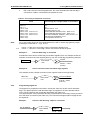
See over for default input/output diagram
Page i
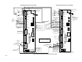
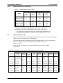
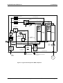
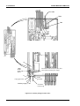
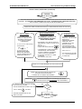
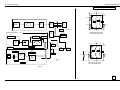
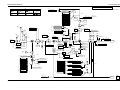
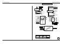
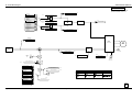
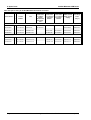
MAINS BRIDGE INPUT/OUTPUT DIAGRAM
MACHINE BRIDGE INPUT/OUTPUT DIAGRAM
+24 V
0V
SFE RUNNING
Lamp supply
Lamp supply
SFE
RUNNING
(24V Lamp)
AT VOLTS
RUNNING
DIGOUT 3
AT SPEED
EARTH
(GROUND)
STOP
RUN
LCN AUX
RUN PERMIT
KEYPAD/REMOTE
(open = Keypad)
TRIP RESET
See Ancillary Components
(Figure 2) for details of
LCN AUX wiring
To Programmable
logic controller...etc.
(Optional)
From line reactor
thermistors
(Figure 2)
LOAD POWER FEEDFORWARD
from Machine Bridge
Screened (shielded) twisted pair must be
used.
Observe polarity +,
9
INTERLOCK
8
DIGIN 1
7
DIGIN 2
6
DIGIN 3
5
DIGIN 4
4
DIGIN 5
STOP
3
2
1
DIGIN 6
+24 V O/P
0 Volts (digital)
AUX S
HSIO HSIO +
CAN LO
CAN HI
GND
RS485 RxRS485 Rx+
RS485 TxRS485 Tx+
TB5
12
11
10
9
8
7
6
5
4
3
2
1
A+
AB+
BZ+
Z+24V
FB+
+5V
0V
FBM_PTC
TB6
9
8
7
6
5
4
3
2
1
3
2
1
+10V
AN I/P 1+
AN I/P 1 AN I/P 2 +
AN I/P 2 -10V
AN GND
AN O/P 1
AN O/P 2
DIGIN 1
RUN
DIGIN 2
TB22
2
4
9
INTERLOCK
8
DIGIN 1
7
DIGIN 2
6
DIGIN 3
5
DIGIN 4
4
DIGIN 5
3
2
1
DIGIN 6
+24 V O/P
0 Volts (digital)
TB7
1
2
Lamp supply:
A 24 V supply is available
for this purpose, at TB3/2
or TB3/10 (+) with
respect to TB2/1 (0 V).
For ratings, see Table 1
on page iv.
AUX S
KEYPAD/REMOTE
(open = Keypad)
ANALOGUE REF1/2
(open = Ref. 1)
TRIP RESET
CLOSE THE "STOP" SWITCH = RUN
OPEN THE "STOP" SWITCH = STOP
At factory default state,
Analogue References are only
available in REMOTE mode
AUX T
TB4
9
8
7
6
5
4
3
2
1
HSIO HSIO +
CAN LO
CAN HI
GND
RS485 RxRS485 Rx+
RS485 TxRS485 Tx+
TB5
12
11
10
9
8
7
6
5
4
3
2
1
A+
AB+
BZ+
Z+24V
FB+
+5V
0V
FBM_PTC
TB6
9
8
7
6
5
4
3
2
1
+10V
AN I/P 1+
AN I/P 1 AN I/P 2 +
AN I/P 2 -10V
AN GND
AN O/P 1
AN O/P 2
High Speed Digital I/O
DC+
To Programmable
logic controller...etc.
(Optional)
Internal
Dynamic
Braking
Unit
(Optional)
From Encoder
and motor PTC
(Figure 2)
R/U
S/V
See Figure 2 for Power Wiring
T/W
REF1: +/-10V
20K
LOAD POWER FEEDFORWARD
to the Mains Bridge
Screened (shielded) twisted pair must be used.
Observe polarity +,
REF2:
4 - 20 mA
LOOP
METER
Speed Feedback
10 V
AN I/P 1
D
Switch
C AN I/P 2
settings
AN O/P 1 shown in their
B
AN O/P 2 factory default
C
state.
Set the DIP switches to
Configure the analogue
I/O for Current or Voltage
operation. Then refer to
menu 7, to configure the
relevant parameters.
20 mA
10 V
4
3
2
1
D
C
B
A
Set the DIP switches to
Configure the analogue
I/O for Current or Voltage
operation. Then refer to
menu 7, to configure the
relevant parameters.
*
SW1
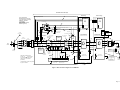
Figure 1 Bi-directional converter input/output diagram (default)
Page ii
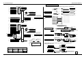
EARTH
(GROUND)
DCDC-
TB4
9
8
7
6
5
4
3
2
1
STOP
DIGOUT 3
AUX R
REVERSE
Alternative RUN/STOP control for single
switch operation, Mains or Machine
bridge:
AUX T
4
SW1
1
2
AUX R
DIGOUT 2
TB3
10 +24V O/P
PLANT INTERLOCK
TB7
CLOSE
LCN
DIGOUT 1
FAN
RUN
20 mA
At each end of cable,
connect screen (shield) to
chassis as shown
FAN
Mains Bridge
PLANT INTERLOCK
X
X
To run drive, INTERLOCK
must be connected to +24V
2
4
RS232 link for Keypad, PC
and PLC connection, on
harbour.
(Update time 100 ms)
TB2
2
+24V Aux Input
1
0V Aux Input
0V
TB22
TB3
10 +24V O/P
ALSPA MV3000e
To run drive, INTERLOCK
must be connected to +24V
HEALTHY
DIGOUT 2
TB2
2
+24V Aux Input
1
0V Aux Input
0V
From PWM
filter fuse
indicator and
thermostat
(Figure 2)
DIGOUT 1
TB1
9
8
7
6
5
4
3
2
1
Lamps on
cabinet door
DC+
Machine Bridge
HEALTHY
TB1
9
8
7
6
5
4
3
2
1
ALSPA MV3000e
Lamps on
cabinet door
RS232 link for Keypad, PC
and PLC connection, on
harbour.
(Update time 100 ms)
Internal
Dynamic
Braking
Unit
(Optional)
R/U
S/V
T/W
AN I/P 1
AN I/P 2
AN O/P 1
AN O/P 2 *
AN O/P 2 switch shown in the AEM Drive
position, NOT in the Default position. The other
three switches are shown in Default position.
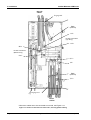
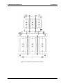
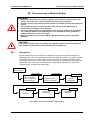
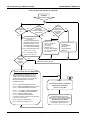
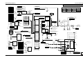
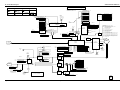
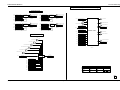
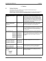
SINUSOIDAL FRONT END (SFE)
Mains Bridge
Ancillary Components
d
Basic configuration
Pre-charge
Circuit
+
Mains
Voltage
Monitor
AUX R
AUX S
AUX T
Fan Transformer
e
(Not
connected)
AUX S
AUX T
TB7
TB7
1
1
Close LCN
110 V
2
2
e
i
R2
Main
Fuses
A1
Fan Transformer
primary fuses
AC Line Reactor
Part /01
c
R3
S1
S2
S3
T1
T2
T3
R4
EMC Filter
(optional
Isolator
(Disconnect)
GLAND
Suppressor
4
4
TB22
TB22
Fan
Fan
BR
Internal
Dynamic
Braking
Unit
(optional)
Line Contactor (LCN)
Auxiliary
fuses
Mains
Network
110 V supply for
customer use
To
AA
Cabinet
Earth (Ground)
2
2
R4
EMC Capacitors
(option)
See Section 3.3
R5
R6
g
R7
R/U
DC +
S4
S4
S5
S5
S6
S7
S/V
T4
T4
T5
T5
T6
T7
T/W
N
X
1
6
INTERLOCK
(Not required)
EMC Capacitors
(option)
See Section 3.3
Thermistor
connections
Cable sizes are designated by
numbers, e.g.
. These numbers
cross-refer to cable sizes given in
Tables 3-3 to 3-5 in Section 3
(Installation).
6
LCN
AUX
PWM filter
fuses and
"fuse blown"
indicator
A
A
h
INTERLOCK
X
e
DC
DC
2
3
4
5
6
M_PTC
0V
TB1
X X
See SFE default input/output
diagram at Figure 1
c
Connect PTC
between:
TB5/1 and TB5/3
f
to
U VW
PTC
Motor Thermistor
TB1
(See Figure 1
inside front cover)
to
TB6
f
* INTERLOCK
Cabinet
Boundary
To TB5
RUN PERMIT
+24 V
7
PWM Filter
TB5
See Figure 1 for
connection details
TB6
1
TB24
T/W
TB3
f
*
S/V
DC
Link
TB5
6
10
From fan
transformer
R/U
DC +
From Encoder
and motor PTC
1
3
f
The specifications of other components
are given in Section 2.
f
*
1
Cabinet
Boundary
ALSPA MV3000
Bi-directional converter
c
c
R5
ALSPA MV3000e
Bi-directional converter
A2
AC Line Reactor
Part /02
Externally fitted
DB Resistor
(optional)
GLAND
230 V fan supply for frame sizes 4, 6 and 7,
not frame size 3
230 V
R1
Pre-charge
Circuit
+
Mains
Voltage
Monitor
AUX R
Ferrite Rings
(optional)
Bi-directional converter (2 off)
Line reactor (parts /01 and /02)
PWM filter + protection
Line contactor
Fan transformer
EMC capacitors (optional)
EMC filter (optional)
Machine Bridge
Load Power Feed Forward
(See Figure 1
inside front cover)
FB+
No te : a m o to r
the rm o sta t c a n
be
a c c o mm o d a te d
b y rep ro g ra m m ing a
d ig ita l inp ut
+5 V
E
OPTIONAL
ENCODER
SFE Running
User Control
Figure 2 Interconnection diagram for an AEM drive
Page iii
0V
FB-
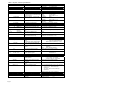
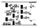
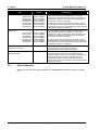
Table 1 I/O panel, connector specifications
TB1
Digital Outputs
Volt-free changeover relay outputs
DIGOUT 1 to 3
TB2
+24 V Aux input
Auxiliary Input Supply
Allows monitoring and programming
with main power switched off.
Digital Inputs
Menu 7
Pin
TB3
Signal
3 to 8
DIGIN 1-6
For remote control of drive – default
functions are shown in the default I/O
diagram (Figure 1).
Impedance:
Active:
Inactive:
Impedance:
15 kΩ
Healthy:
+12 V to +50 V
Unhealthy:
Open circuit or < 7 V
Volts range:
+22.8 V to +25.3 V
Max load:
500 mA
Connected to earth (ground) internally
Specifications
9
INTERLOCK
Hardware interlock – must be made
to enable drive.
2 & 10
+24 V O/P
User supply for peripheral equipment.
1
0 V (digital)
TB4
TB4A TB4B
Pin Pin
Pin
Signal
0 V reference of digital inputs.
Communications
1/2
3/4
15 kΩ
+12 V to +50 V
Open circuit or < 7 V
1/2
3/4
RS485 Tx +/–
RS485 Rx +/–
Differential link for improved noise
immunity (Menu 32).
0 - 2 km range. Update time 10 ms.
5/6
GND
CAN 0 V
Common ground for communications
links.
Connected to earth (ground) internally.
1
4/2
3
CAN HI/LO
SCN
Connection to CANopen or to
expanded I/O.
Future
HSIO +/–
High speed digital link (Menu 20).
(Not available in SFE mode)
RS422 protocol, ± signal differential with respect
to GND pin. Common mode ≅ 15 V
5
6/7
Specifications
250 Vac, 30 Vdc
3 A (resistive load)
Specifications
Current, nominal (Keypad+Controller) : 500 mA
Current, max (all versions) : 2.2 A
Specifications
Max volts :
Max current :
8/9
7/8
Pin
TB5
Signal
Encoder/PTC
Menu 13
1
M_PTC
Input from motor thermistor (machine
bridge)
Input from line reactor (mains bridge).
2/5
FB –/FB+
Encoder power supply feedback for
accurate setting.
4/6
+5 V/+24 V
Power supply outputs for the
encoder.
3
0V
Common return line for encoder
power supply and the PTC.
Connected to earth (ground) internally.
7/8
9 - 12
Z–/Z+
B–/B+, A–/A+
Marker signal from encoder.
Encoder position signals.
EIA RS422A, Max edge freq 1.5 MHz,
see Section 3.9
Pin
TB6
Signal
Specifications
0 Ω to 10 kΩ (P2.13 motor
PTC, P52.19 SFE choke PTC)
Reset: (Value in parameter) –0.1 kΩ
Resistive: Trip:
+5 V:
+24 V:
1/2
ANOP 1 and 2
3
AN GND
4/9
–10 V/+10 V to
5/6
7/8
AN I/P 2 –/+
AN I/P 1 –/+
Pin
TB7 (pre-charge pcb)
Signal
1/2
Page iv
CLOSE LCN
Analogue Inputs/Outputs
Menu 7
Analogue outputs 1 and 2, V or I as
selected by SW1.
Analogue ground (earth) for inputs
and outputs.
......... Reference supplies for analogue
inputs.
Differential analogue input 2
Differential analogue input 1
Relay Output
Line contactor pilot relay output
(volts free)
Adjustable, 4.5 - 6.5 V, 350 mA
maximum
Fixed, 350 mA maximum
Specifications
V or I:
(11 bit + sign), ±5% full scale accuracy, ..
V:
–10 V to +10 V, ≤ 5 mA load
I:
–20 mA to +20 mA, ≤ 500 Ω load
Connected to earth (ground) internally.
Maximum Load : 5 mA current limited
V or I as selected by SW1 (11 bit + sign), ±5% full
scale accuracy:
V:
–10 V to +10 V, 100 kΩ load input
impedance.
I:
–20 mA to +20 mA, 235 Ω load input
impedance.
Common mode volts = ±2.5 V maximum.
Specifications
D.1.1
Maximum volts : 500 Vac
Maximum current :
8A
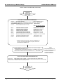
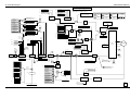
ALSPA MV3000e AEM Drives
THIS MANUAL
(T2002EN)
OVERVIEW
&
SPECIFICATIONS
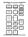
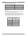
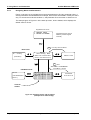
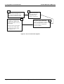
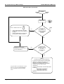
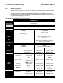
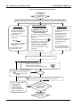
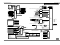
Documentation Structure
STAGES OF USE
PLANNING
+
PRODUCT SELECTION
OPTIONAL
MANUALS
BUYER'S GUIDE
(SECTIONS 1&2)
OPTIONS AVAILABLE
(SECTION 9)
DELTA DRIVE?
OPTIONAL EXTRAS?
DELTA MANUALS
(T1689, T1693)
OPTION MANUALS
INSTALLATION INSTRUCTIONS
FOR MAINS BRIDGE,
SINUSOIDAL FRONT END
AND
MACHINE BRIDGE
INSTALLATION
EVERY OPTION HAS
INDIVIDUAL
INSTALLATION
INSTRUCTIONS
(SECTION 3)
DELTA MANUALS
(T1689, T1693)
INSTALLATION OF
MODULAR DRIVES
HOW TO USE THE KEYPAD
+
DEFAULT SET-UP
+
FLOWCHARTS FOR
GUIDED COMMISSIONING
+
SIMPLE
APPLICATION EXAMPLES
COMMISSIONING
(SECTIONS 4, 5A, 5B)
FULL SYSTEM SOFTWARE
DIAGRAMS
(SECTION 5C)
(06/06)
PROGRAMMING
FOR FINAL
APPLICATION
SOLUTIONS
SIMPLE MAINTENANCE
(SECTION 6)
DIAGNOSTICS AND USE OF
ON-LINE HELP
(SECTION 7)
MAINTENANCE
+
DIAGNOSTICS
BASIC SPARES
(SECTION 8)
+
AVAILABLE OPTIONS
(SECTION 9)
+
DISPOSAL INSTRUCTIONS
(SECTION 10)
SPARES
+
OPTIONS
+
DISPOSAL
SOFTWARE MANUAL
(T1679EN)
DETAILED
DESCRIPTION OF
DRIVE PARAMETERS
+
USEFUL APPLICATION
PROGRAMMING
EXAMPLES
SOFTWARE MANUAL
(T1679EN)
DIAGNOSTIC
FLOWCHARTS
+
EXTRA DIAGNOSTIC
INFORMATION
ALSPA MV3000e Getting Started Manual for AEM Drives
Page v
ALSPA MV3000e AEM Drives
This page intentionally left blank
Page vi
ALSPA MV3000e Getting Started Manual for AEM Drives
(06/06)
ALSPA MV3000e AEM Drives
Overview
OVERVIEW
Section
1.
Page
Introduction...................................................................................................................... 1-1
Introduces the Getting Started Manual and the concept of Active Energy Management (AEM).
Explains the terminology used to describe the components of AEM drives.
2.
Product Data .................................................................................................................... 2-1
Lists the complete range of Converteam MicroCubicle™ bi-directional converters. Provides
electrical and mechanical data for the bi-directional converter, configured either as a Mains
Bridge in a Sinusoidal Front End (SFE), or as a Machine Bridge; also provides physical
dimensions and miscellaneous data common to all the converters, such as derating
information.
3.
Installation........................................................................................................................ 3-1
Explains how to properly install a MicroCubicle™ bi-directional converter, ready for
commissioning, either as part of a SFE or as a machine bridge. Mechanical aspects include
the illustrated layout of components with regard to ventilation and EMC requirements.
Electrical installation instructions include the layout of cables for EMC requirements,
segregation, access to drive connectors and cable connection.
4.
Using Menus and Parameters ........................................................................................ 4-1
Explains the system of menus and parameters which is used to configure the converter
during commissioning. Shows how to use the Drive Data Manager™ to navigate the menus
and enter parameter values. Shows how to get on-line help.
5A.
Commissioning a Mains Bridge ....................................................................................5A-1
Explains how to configure a mains bridge as part of a SFE, to generate a controlled DC
voltage, using factory default settings. Explains how to configure the converter in more detail
using Guided Commissioning (simple flowcharts) and the Control Block Diagrams supplied
in Section 5C.
5B.
Commissioning a Machine Bridge................................................................................5B-1
Explains how to configure a machine bridge to turn a motor, using factory default settings,
also how to configure the drive in more detail using Guided Commissioning (simple
flowcharts) and shows how to set up the drive for more advanced applications, using the
Control Block Diagrams supplied in Section 5C.
5C.
Control Block Diagrams................................................................................................ 5C-1
Provides a graphic representation of the converter parameters. Explains how to use these
diagrams to design customised applications.
6.
Preventive Maintenance.................................................................................................. 6-1
Simple maintenance procedures for keeping MicroCubicle™ bi-directional converters
serviceable.
7.
Diagnostics ...................................................................................................................... 7-1
What to do if the MicroCubicle™ bi-directional converter displays a WARNING or if it TRIPS.
Shows how to display Warning and Trip codes, and tabulates the meaning of these codes.
Provides many diagnostic hints to help find possible faults, explains how to reset the
converter and how to view a history of any previous incidents which may help with diagnosis.
8.
(06/06)
Spare Parts........................................................................................................................ 8-1
ALSPA MV3000e Getting Started Manual for AEM Drives
Page vii
Overview
ALSPA MV3000e AEM Drives
Lists spare parts which may be obtained from the MicroCubicle™ bi-directional converter
supplier to replace faulty items. Associated Part Nos. are included.
9.
Options .............................................................................................................................. 9-1
Lists and briefly describes the optional equipment and manuals which can be obtained from
the MicroCubicle™ bi-directional converter supplier.
10.
Disposal.......................................................................................................................... 10-1
Provides disposal instructions for the MicroCubicle™ bi-directional converter, and advises of
any toxic materials and special procedures to dispose of them.
Page viii
ALSPA MV3000e Getting Started Manual for AEM Drives
(06/06)
ALSPA MV3000e AEM Drives
Contents
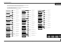
CONTENTS
Section
Page
Safety Instructions ................................................................................................................. i
Bi-directional converter input/output diagram (default) ...............................................................ii
Interconnection diagram for an AEM drive ...................................................................................iii
Input/Output panel, connector specifications...............................................................................iv
Documentation Structure .................................................................................................................v
Overview ..........................................................................................................................................vii
Contents............................................................................................................................................ix
1.
1.1
1.2
1.1
1.2
1.3
1.3.1
1.2.1
1.2.2
1.2.3
1.2.4
1.4
1.4.1
1.2.5
1.2.6
1.3
1.5
1.6
Introduction............................................................................................................................ 1-1
About this Manual.................................................................................................................... 1-1
About ALSPA MV3000e MicroCubicleTM Bi-directional Converters ........................................ 1-1
Drive Data Manager™ (Keypad) ............................................................................................. 1-2
Explanation of Product Code................................................................................................... 1-2
Terminology ............................................................................................................................. 1-2
Bi-directional Converter...................................................................................................... 1-2
Rectifier-fed Drive............................................................................................................... 1-3
Mains Bridge....................................................................................................................... 1-3
Sinusoidal Front End (SFE)................................................................................................ 1-3
Machine Bridge .................................................................................................................. 1-4
Typical Applications Using Bi-directional Converters.............................................................. 1-5
AEM Drive using two identical Bi-directional Converters ................................................... 1-5
AEM Drive using a Bi-directional Converter and a Rectifier-fed Drive............................... 1-5
Common DC Link Scheme with Several Machine Bridges ................................................ 1-6
Use of Metric Units .................................................................................................................. 1-7
Customer Support and Training .............................................................................................. 1-7
Associated Publications........................................................................................................... 1-7
2.
2.1
2.2
2.3
2.4
2.4.1
2.4.2
2.5
2.5.1
2.5.2
2.6
2.6.1
2.6.2
2.7
2.8
2.8.1
2.8.2
2.8.3
2.9
2.9.1
2.9.2
2.9.3
2.10
2.11
2.12
Product Data .......................................................................................................................... 2-1
Rating Data for Bi-directional Converters Configured as Machine Bridges ............................ 2-1
Rating Data for Bi-directional Converters Configured as Mains Bridges ................................ 2-2
MicroCubicle™ Dimensions .................................................................................................... 2-3
AC Line Reactor ...................................................................................................................... 2-4
Physical Dimensions, Inductance and Losses................................................................... 2-4
Fixing Dimensions .............................................................................................................. 2-5
PWM Filter ............................................................................................................................... 2-6
Physical Dimensions and Losses....................................................................................... 2-6
Fixing Dimensions .............................................................................................................. 2-7
Fan Transformer...................................................................................................................... 2-8
Physical Dimensions and Losses....................................................................................... 2-8
Electrical Data for Fan Transformer ................................................................................... 2-9
Line Contactor LCN ................................................................................................................. 2-9
Electrical and Environmental Specifications ......................................................................... 2-10
Common Specifications.................................................................................................... 2-10
Specifications for Machine Bridges .................................................................................. 2-10
Specifications for Sinusoidal Front End (SFE) ................................................................. 2-11
Product Performance Data .................................................................................................... 2-11
Product performance data for Machine Bridges .............................................................. 2-11
Product performance data for Sinusoidal Front End........................................................ 2-12
Mains Impedance ............................................................................................................. 2-12
DC Link Overvoltage Trip Levels........................................................................................... 2-13
Acoustic Noise Levels ........................................................................................................... 2-13
Standards .............................................................................................................................. 2-14
3.
3.1
3.2
3.2.1
Installation.............................................................................................................................. 3-1
Introduction .............................................................................................................................. 3-1
Receipt of Equipment .............................................................................................................. 3-1
Inspection and Storage ...................................................................................................... 3-1
(06/06)
ALSPA MV3000e Getting Started Manual for AEM Drives
Page ix
Contents
ALSPA MV3000e AEM Drives
3.2.2
3.3
3.3.1
3.3.2
3.4
3.4.1
3.4.2
3.5
3.5.1
3.5.2
3.5.3
3.6
3.6.1
3.6.2
3.7
3.7.1
3.7.2
3.7.3
3.7.4
3.7.5
3.8
3.9
3.10
3.11
3.12
3.12.1
3.12.2
3.13
3.13.1
3.13.2
3.14
3.14.1
3.14.2
3.15
Handling ..............................................................................................................................3-2
Harmonic Recommendations...................................................................................................3-3
AC Line Reactors ................................................................................................................3-3
PWM Filters.........................................................................................................................3-3
EMC Recommendations ..........................................................................................................3-3
EMC Filter and Capacitors..................................................................................................3-3
Cabinet Layout for EMC Compliance .................................................................................3-4
Mechanical Installation.............................................................................................................3-6
Cooling and Environment....................................................................................................3-6
Clearances and Mounting Distances ..................................................................................3-7
Mounting Checklist..............................................................................................................3-7
Electrical Installation - General ................................................................................................3-8
Protection devices...............................................................................................................3-8
Cable Lugs and Recommended Torque Settings...............................................................3-9
Cable Selection ......................................................................................................................3-10
AC Power Cable Selection................................................................................................3-10
DC Link Cable Selection ...................................................................................................3-11
DC Link Cable Screening and Segregation ......................................................................3-12
Ancillary and Control Cable Selection ..............................................................................3-12
Cable Segregation ............................................................................................................3-13
Suitability of Motors and Cables ............................................................................................3-13
Encoders and Encoder Cables ..............................................................................................3-14
Access to Electrical Connections...........................................................................................3-15
Control Connections...............................................................................................................3-17
Cable Connections - Frame Sizes 3 and 4 ............................................................................3-19
AC Power and Motor Cables ............................................................................................3-19
DC Link and Ancillary Cables ...........................................................................................3-21
Cable Connections - Frame Size 6 ........................................................................................3-23
AC Power, Motor and DC Link Cables .............................................................................3-23
Ancillary Cables ................................................................................................................3-25
Cable Connections - Frame Size 7 ........................................................................................3-27
AC Power, Motor and DC Link Cables .............................................................................3-27
Ancillary Cables ................................................................................................................3-30
Ancillary Components ............................................................................................................3-31
4.
4.1
4.1.1
4.2
4.2.1
4.2.2
4.2.3
4.2.4
4.2.5
4.2.6
4.2.7
4.3
4.4
4.4.1
4.4.2
4.4.3
4.5
4.5.1
4.5.2
4.6
Using Menus and Parameters...............................................................................................4-1
Menu Structure Overview.........................................................................................................4-1
Parameters..........................................................................................................................4-1
Use of the Drive Data Manager™ (Keypad) ............................................................................4-1
Navigation Key ....................................................................................................................4-1
Navigating Menus and Parameters ....................................................................................4-2
Editing Parameters .............................................................................................................4-3
Using the Keypad HELP (?) Key.........................................................................................4-5
SHORTCUT Method of Entering a Parameter Number......................................................4-5
Access to Other Menus (P1.31)..........................................................................................4-5
Keypad Removal.................................................................................................................4-6
Keypad Harbour Status Indicators ...........................................................................................4-7
Application Programming .........................................................................................................4-8
Control Flags and Status Flags...........................................................................................4-8
Programming Digital I/O......................................................................................................4-9
Programming Analogue I/O ..............................................................................................4-10
Security Attributes and Passwords ........................................................................................4-10
Attributes ...........................................................................................................................4-10
Parameter Passwords.......................................................................................................4-11
Control Block Diagrams .........................................................................................................4-11
5A.
5A.1
5A.2
5A.3
5A.3.1
Commissioning a Mains Bridge............................................................................................... 1
Introduction.................................................................................................................................. 1
Installation Assumptions ............................................................................................................. 2
Menu Structure Overview............................................................................................................ 3
Menu Listing........................................................................................................................... 3
Page x
ALSPA MV3000e Getting Started Manual for AEM Drives
(06/06)
ALSPA MV3000e AEM Drives
Contents
5A.3.2
5A.3.3
5A.3.4
5A.4
5A.4.1
5A.4.2
5A.4.3
5A.5
Menu 1....................................................................................................................................3
Default Configuration..............................................................................................................6
Returning to Factory Default Settings ....................................................................................7
Commissioning Procedure ..........................................................................................................7
Introduction.............................................................................................................................7
Simple Start ............................................................................................................................8
Guided Commissioning of a SFE ...........................................................................................9
Application Programming ..........................................................................................................13
5B.
5B.1
5B.2
5B.3
5B.3.1
5B.3.2
5B.3.3
5B.3.4
5B.4
5B.4.1
5B.4.2
5B.4.3
5B.5
Commissioning a Machine Bridge...........................................................................................1
Introduction ..................................................................................................................................1
Installation Assumptions..............................................................................................................2
Menu Structure Overview ............................................................................................................2
Menu Listing ...........................................................................................................................2
Menu 1....................................................................................................................................3
Default Configuration..............................................................................................................6
Returning to Factory Default Settings ....................................................................................7
Commissioning Procedure ..........................................................................................................7
Introduction.............................................................................................................................7
Simple Start ............................................................................................................................8
Guided Commissioning of a Machine Bridge .........................................................................9
Application Programming ..........................................................................................................22
5C.
Control Block Diagrams............................................................................................................1
6.
6.1
6.2
Preventive Maintenance........................................................................................................ 6-1
Tools and Equipment Required............................................................................................... 6-1
Maintenance Schedules .......................................................................................................... 6-1
7.
7.1
7.1.1
7.2
7.3
7.4
7.4.1
7.4.2
7.4.3
7.4.4
7.5
7.6
7.6.1
7.6.2
7.6.3
Diagnostics ............................................................................................................................ 7-1
LED Indicators ......................................................................................................................... 7-1
Fault Indication ................................................................................................................... 7-1
Warnings.................................................................................................................................. 7-1
Trips......................................................................................................................................... 7-1
Viewing Warnings and Trips.................................................................................................... 7-1
Action in the Event of a Warning ........................................................................................ 7-2
Action in the event of a Trip................................................................................................ 7-2
Resetting Trips ................................................................................................................... 7-2
Trip Fault Codes ................................................................................................................. 7-2
Using the HELP Key................................................................................................................ 7-2
Diagnostic Hints....................................................................................................................... 7-3
Changing Pcb's .................................................................................................................. 7-4
Failure of Converter Firmware ........................................................................................... 7-4
Uploading the Converter Memory Contents to a PC.......................................................... 7-4
8.
8.1
8.1.1
8.2
Spare Parts............................................................................................................................. 8-1
Pre-charge Fuses .................................................................................................................... 8-1
Replacing Pre-charge Fuses.............................................................................................. 8-1
Spare Parts Listing .................................................................................................................. 8-3
9.
9.1
9.2
Options ................................................................................................................................... 9-1
Optional Hardware................................................................................................................... 9-1
Optional Manuals..................................................................................................................... 9-2
10.
Disposal................................................................................................................................ 10-1
(06/06)
ALSPA MV3000e Getting Started Manual for AEM Drives
Page xi
Contents
ALSPA MV3000e AEM Drives
This page intentionally left blank
Page xii
ALSPA MV3000e Getting Started Manual for AEM Drives
(06/06)
ALSPA MV3000e AEM Drives
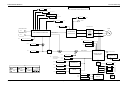
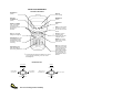
1. Introduction
1. Introduction
1.1
About this Manual
This Getting Started Manual provides a competent user trained in electrical installation
practice with sufficient information to safely install, commission, operate, maintain and dispose
of simple Active Energy Management (AEM) systems, based on the MV3000e series of
bi-directional converters.
This manual should be regarded as part of the product. It should be retained for the life of the
product and passed on to any subsequent owner or user.
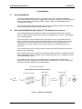
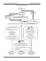
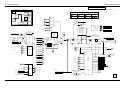
About ALSPA MV3000e MicroCubicleTM Bi-directional Converters
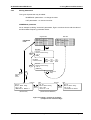
1.2
Active Energy Management systems are based on the MV3000e bi-directional converter,
which is a MicroCubicle™ style product that can be configured by the user as a mains bridge
or as a machine bridge:
The mains bridge is combined with ancillary components to form a Sinusoidal Front End
(SFE). The SFE accurately controls the bi-directional flow of power between the AC mains
supply and a DC bus (normally referred to as the "DC Link"). The current drawn from, or
regenerated to, the mains supply is at unity power factor and is substantially free from
harmonics.
The machine bridge controls a motor and the bi-directional power flow between the DC bus
and the motor or generator.
When a SFE and a machine bridge are connected at their DC terminals, an AEM drive (Active
Energy Management Drive) is created, also sometimes referred to as a "4-quadrant AC drive".
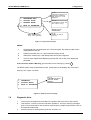
This is illustrated in Figure 1-1.
For simplicity, in this manual most examples assume a configuration comprising a bidirectional converter configured as a mains bridge, connected via a DC link to an identical bidirectional converter configured as a machine bridge.
Sinusoidal Front End (SFE)
Mains Bridge
Machine Bridge
Ancillary Componets
Motor
3
Mains
Network
DC link
3
M
Figure 1-1 AEM Drive arrangement
(06/06)
ALSPA MV3000e Getting Started Manual for AEM Drives
Page 1-1
1. Introduction
1.1
ALSPA MV3000e AEM Drives
Drive Data Manager™ (Keypad)
The converter can be configured for use by means of an optional Drive Data Manager™
(keypad) and a simple menu system. The keypad can be mounted directly to the front of the
converter, or may be panel mounted using an optional mounting kit and connected to the
converter via a cable.
1.2
Explanation of Product Code
The MicroCubicle™ bi-directional converters covered by this manual are listed in Tables 2-1
and 2-2 in Section 2. The code used to identify bi-directional converters is illustrated in Figure
1-2, using the code for an ALSPA MV3000e bi-directional converter, rated at 140 A with a
nominal supply voltage of 400 V.
Current
Bi-directional
Rating (Amps) Converter
ALSPA
MV3000
Series
Voltage Overload Rating
Rating Selectable 1.1/1.5
Standard
Fan
MV3140J5A1
Figure 1-2 ALSPA MV3000eJ bi-directional converter identity code
The voltage and current ratings are given in Section 2, Tables 2-1 and 2-2. Dimensions and
weights are provided in Section 2.3.
1.3
Terminology
1.3.1
Bi-directional Converter
A MicroCubicle™ style product that can be configured (in both hardware and software) to
operate as a mains bridge (a component of a SFE) or as a machine bridge.
Identifiable by the letter J in the part number, e.g. MV3071J5A1.
Contains mains voltage monitoring circuits to allow synchronisation to the mains when
operating as a mains bridge.
The default software operating mode is SFE mode, in which it functions as a mains bridge.
A simplified representation of the bi-directional converter is illustrated in Figure 1-3.
3-phase AC
DC
OR
DC
3-phase AC
Figure 1-3 Simplified representation of a Bi-directional converter
Page 1-2
ALSPA MV3000e Getting Started Manual for AEM Drives
(06/06)
ALSPA MV3000e AEM Drives
1.2.1
1. Introduction
Rectifier-fed Drive
Also sometimes referred to as an "AC in AC out drive" or "AC-fed drive", the Rectifier-fed
drive:
Comprises a MicroCubicle™ style product which combines the functions of a diode rectifier
bridge and a machine bridge, as shown in Figure 1-4.
Identifiable by the letter A in the part number, e.g. MV3065A5A1
Typically AC-fed and as such provides unidirectional power flow from the mains to an AC
induction motor, but can alternatively be DC-fed to allow bidirectional power flow between DC
and an AC induction machine.
Can form part of an AEM drive or a common DC link scheme.
Covered by manual T1676.
Rectifier
Machine bridge
3-phase
mains
3-phase
machine
DC
Figure 1-4 Simplified representation of a rectifier-fed drive
1.2.2
Mains Bridge
The mains bridge forms part of the Sinusoidal Front End (SFE), described in
Section 1.2.3.
1.2.3
Sinusoidal Front End (SFE)
Also sometimes referred to as a "DC feeder", the SFE:
Converts electrical energy from AC mains to DC, or vice versa. Its primary function is to
actively control the voltage at its DC terminals. To achieve this it can sink or source near
sinusoidal current to or from the AC mains.
Consists of a bi-directional converter configured with software to function as a mains bridge,
plus ancillary components as shown in Figure 2 at the front of this manual.
Can form part of an AEM drive or a common DC link scheme, described later.
The DC link is automatically precharged as soon as a voltage is applied to the AUX terminals.
If a "Run" signal is not applied, or if the mains bridge is stopped or tripped, the SFE functions
as a diode rectifier.
Figure 1-5 shows a simplified block diagram of a SFE.
(06/06)
ALSPA MV3000e Getting Started Manual for AEM Drives
Page 1-3
1. Introduction
ALSPA MV3000e AEM Drives
Sinusoidal Front End
Ancillary
components
*
Mains Bridge
Bi-directional
converter
3-phase
mains
DC
*
Refer to Figure 2 on page iii
Figure 1-5 Simplified representation of a Sinusoidal Front End
1.2.4
Machine Bridge
Also sometimes referred to as a "DC-fed drive", the machine bridge:
Converts electrical energy from DC into AC, or vice versa. Its primary function is to perform
speed or torque control of an AC induction motor or generator.
May consist of a bi-directional converter which has been software configured to operate in one
of several possible drive modes, including frequency control (VVVF), vector control (with
or without encoder), or scalar control.
Alternatively may consist of a rectifier-fed drive with its rectifier bridge unused.
Can form part of an AEM drive or a common DC link scheme, described later.
Figure 1-6 shows a simplified block diagram of a machine bridge.
Machine Bridge
DC
3-phase
machine
Figure 1-6 Simplified representation of a bi-directional converter configured as a machine bridge
Page 1-4
ALSPA MV3000e Getting Started Manual for AEM Drives
(06/06)
ALSPA MV3000e AEM Drives
1. Introduction
1.4
Typical Applications Using Bi-directional Converters
1.4.1
AEM Drive using two identical Bi-directional Converters
AEM Drive
Sinusoidal Front End
Mains Bridge
Machine Bridge
Ancillary
components
3-phase
mains
3-phase
machine
Figure 1-7 Simplified representation of an AEM drive using two identical bi-directional conveters
See Section 2 for rating details.
1.2.5
AEM Drive using a Bi-directional Converter and a Rectifier-fed Drive
AEM Drive
Rectifier-fed Drive
(Not used)
Rectifier
Sinusoidal Front End
Mains Bridge
Machine Bridge
Ancillary
components
3-phase
mains
3-phase
machine
Figure 1-8 Simplified representation of an AEM drive using a SFE and a rectifier fed drive
(06/06)
ALSPA MV3000e Getting Started Manual for AEM Drives
Page 1-5
1. Introduction
ALSPA MV3000e AEM Drives
Table 1-1 shows the model numbers of mains bridges and rectifier-fed drives which may be
used together to make an AEM drive.
Table 1-1 MV3000e Compatibility table for AEM drive creation
Mains bridge
Compatible rectifier-fed drives for use as machine bridges *
MV3071J5A1
MV3065A5A1
MV3052A5A1
MV3140J5A1
MV3124A5A1
MV3096A5A1
MV3077A5A1
MV3364J5A1
MV3302A5A1
MV3240A5A1
MV3180A5A1
MV3566J5A1
MV3477A5A1
MV3414A5A1
MV3361A5A1
MV3099J6A1
MV3099A6A1
MV3077A6A1
MV3062A6A1
MV3242J6A1
MV3242A6A1
MV3192A6A1
MV3144A6A1
MV3382J6A1
MV3382A6A1
MV3336A6A1
MV3289A6A1
MV3156A5A1
MV3125A6A1
* Refer to Converteam manual T1676 for ratings of MV3000e Rectifier-fed products.
1.2.6
Common DC Link Scheme with Several Machine Bridges
The bi-directional converter can be used in a common DC link scheme in which a SFE and
several machine bridges of various ratings drive a number of motors, as shown in Figure 1-9.
These motors may draw or regenerate power independently and thereby increase the system
efficiency by reducing the current drawn from the mains. Further information may be obtained
from the supplier.
Machine Bridges
Motors
3
M
Sinusoidal Front End (SFE)
3
3
Mains
Network
Common DC link
M
3
M
3
M
Figure 1-9 Common DC link scheme with several machine bridges
Page 1-6
ALSPA MV3000e Getting Started Manual for AEM Drives
(06/06)
ALSPA MV3000e AEM Drives
1.3
1. Introduction
Use of Metric Units
The ALSPA MV3000e range of bi-directional converters has been designed to IEC standards
using SI units. In this manual approximate values for inches, lb and hp are also included for
convenience.
1.5
Customer Support and Training
Converteam provides comprehensive telephone technical support, application planning,
service and trsaining for customers.
Contact Converteam at the address and telephone numbers shown at the end of this manual.
1.6
Associated Publications
1.6.1.1.1
T1676 ALSPA MV3000e Getting Started Manual for AC-fed Drives
This manual provides a competent user trained in electrical installation practice
with sufficient information to safely install, commission, operate, maintain and
dispose of a simple AC-fed drive installation.
1.3.1.1.1
T1679 ALSPA MV3000e Software Technical Manual
This manual includes full descriptions of the menu structure and parameters and
also the serial communications systems.
1.3.1.1.2
T1684 ALSPA MV3000e Dynamic Braking Units
Comprehensive instructions are provided to allow a competent user to install,
commission, maintain the MV3DB series DB Units, and to select and install the
associated braking resistors.
1.3.1.1.3
T2013 ALSPA MV3000e CANopen Fieldbus Facility Technical Manual
This manual enables a competent user trained in drives to use the on-board
CANopen facility to add input/output functions (extended I/O) and to configure
communication between two or more drives, using the CANopen Fieldbus.
1.3.1.1.4
T1689 ALSPA MV DELTA, Technical Manual for MV3000e DELTA
T1693 ALSPA MV DELTA Liquid Cooled Drive System
These manuals include specifications and instructions to allow a competent user
trained in drives to safely install the components of ALSPA MV3000e DELTA
systems to construct DELTA drives.
DELTA drives are a unique system of modular based drive units,150 kW to 1.8 MW
in air-cooled versions, 600 kW to 3.6 MW in liquid cooled versions.
1.3.1.1.5
T1933 ALSPA MV3000e MicroPEC Application Processor
This instruction sheet enables a competent user trained in drives to install the
MicroPEC facility and use it to add complex processor-based functions to the
simple logic functions provided as standard with the drive.
(06/06)
ALSPA MV3000e Getting Started Manual for AEM Drives
Page 1-7
1. Introduction
ALSPA MV3000e AEM Drives
This page intentionally left blank
Page 1-8
ALSPA MV3000e Getting Started Manual for AEM Drives
(06/06)
ALSPA MV3000e AEM Drives
2. Product Data
2. Product Data
2.1
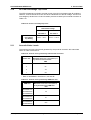
Rating Data for Bi-directional Converters Configured as Machine Bridges
Note:
The data in Table 2-1 is correct for a PWM switching frequency of 1.25 kHz. For data at other switching frequencies refer to Converteam.
Table 2-1 Rating data for bi-directional converters configured as machine bridges
Converter
Model
G
r
a
d
e
DC Link
Frame
Size
Voltage
V
Motor Rating
Nominal
Voltage
Current
1.1/1.5 O/L
A
V
3
450 - 850
88/72
4
450 - 850
176/130
MV3364J5A1
6
450 - 850
462/370
MV3566J5A1
7
450 - 850
672/552
MV3071J5A1
3
450 - 850
81/65
4
450 - 850
159/120
6
450 - 850
391/314
7
450 - 850
673/526
4
600 - 1100
127/96
600
@ 60 Hz
(500 V
to
690 V)
MV3071J5A1
MV3140J5A1
MV3140J5A1
MV3364J5A1
S
T
D
A
L
T
MV3566J5A1
MV3099J6A1
MV3242J6A1
S
T
D
MV3382J6A1
MV3099J6A1
MV3242J6A1
MV3382J6A1
A
L
T
400
@ 50 Hz
(380 V
to
440 V)
480
@ 60 Hz
(460 V
to
525 V)
6
600 - 1100
314/252
7
600 - 1100
460/369
4
600 - 1140
122/102
690
@ 50 Hz
(data valid
for 690 V
only)
6
600 - 1140
268/215
7
600 - 1140
435/400
Nominal Power
1.1 O/L
kW
Nominal Power
Drive Output Current
Heat Losses to Cabinet†
Continuous Current
(Maximum Current)
Approx. Maximum Losses
1.1 O/L
A
With Dirty
Air Kit Fitted
W
AEM Drive
Airflow required by
cabinet
Suitable SFE to
produce an
AEM Drive
1.5 O/L
kW
1.1 O/L
HP
37
30
50
40
71 (78)
58 (87)
1.1
200
140
85
MV3071J5A1
75
55
101
74
140 (154)
105 (158)
1.6
260
255
150
MV3140J5A1
200
160
268
214
364 (401)
292 (438)
3.3
440
680
400
MV3364J5A1
309
248
413
330
524 (576)
407 (611)
5.1
580
850
500
MV3566J5A1
37
30
50
40
65 (72)
52 (78)
1.1
200
140
85
MV3071J5A1
75
56
100
75
124 (137)
96 (144)
1.6
260
255
150
MV3140J5A1
187
149
250
200
302 (332)
240 (360)
3.3
440
680
400
MV3364J5A1
364
291
486
388
516 (568)
400 (601)
5.1
580
850
500
MV3566J5A1
75
56
100
75
99 (109)
77 (116)
1.6
260
255
150
MV3099J6A1
187
149
250
200
242 (266)
192 (288)
3.3
440
680
400
MV3242J6A1
309
249
412
332
352 (387)
284 (425)
5.1
580
850
500
MV3382J6A1
90
75
121
101
98 (108)
82 (123)
1.6
260
255
150
MV3099J6A1
200
160
268
214
211 (232)
170 (255)
3.3
440
680
400
MV3242J6A1
342
276
456
368
339 (373)
273 (410)
5.1
580
850
500
MV3382J6A1
1.5 O/L
HP
. δAC Voltage Grade - Selectable by parameter P99.11
STD = Standard AC Voltage Grade
ALT = Alternate AC Voltage Grade
1.5 O/L
A
Clean Air
Configuration
kW
Ventilation
t
(P99.11 = 0)
(P99.11 = 1)
3
m /h
cu ft/min
These are heat losses from the bi-directional
converter. Losses from other components are given
with the component data elsewhere in Section 2.
.Overload (O/L) ratings - Selectable by parameter P99.02 (P1.29)
1.1 rating = 1.1 overload, i.e. 1.1 x full load current (P99.02 = 1)
1.5 rating = 1.5 overload, i.e. 1.5 x full load current (P99.02 = 0)
Section 2.8 gives maximum permitted overload repetition rate.
OUTPUT DE-RATING
ALTITUDE:
Nominal 0 to 1000 m, above 1000 m de-rate 7.3% per 1000 m to a maximum of 2000 m.
TEMPERATURE: Nominal 0ο C to 40ο C, above 40ο C de-rate 2.5% per ο C to a maximum of 50ο C.
(06/06)
ALSPA MV3000e Getting Started Manual for AEM Drives
Page 2-1
2. Product Data
2.2
ALSPA MV3000e AEM Drives
Rating Data for Bi-directional Converters Configured as Mains Bridges
Note:
The data in Table 2-2 is correct for a PWM switching frequency of 2.5 kHz. For data at other switching frequencies refer to Converteam.
Table 2-2 Fusing and rating data for bi-directional converters configured as mains bridges
Converter
Input
Line Reactor
Mains Rating
PWM Filter
Fuses
PWM Filter
δ
Model
G
r
a
d
e
MV3364J5A1
V
3
MV3071J5A1
MV3140J5A1
Frame
Size
S
T
D
4
6
MV3566J5A1
7
MV3071J5A1
3
MV3140J5A1
MV3364J5A1
A
L
T
4
6
MV3566J5A1
7
MV3099J6A1
4
MV3242J6A1
MV3382J6A1
S
T
D
MV3382J6A1
6
7
4
MV3099J6A1
MV3242J6A1
Nominal
Voltage
A
L
T
6
7
400
@ 50 Hz
(380 V
to
440 V)
480
@ 60 Hz
(440 V
to
480 V)
600
@ 60 Hz
(500 V
to
600 V)
690
@ 50 Hz
(500 V
to
690 V)
Mains
Current
(1.1/1.5 O/L)
A
IEC Rated
Fuse **
(1.1/1.5 O/L)
A
UL Rated
Fuse **
(1.1/1.5 O/L)
A
Rating **
Model Number
(Parts
/01 and /02)
Model Number
IEC
A
UL/CSA
A
Heat Losses in Cabinet†
DC Link
DC Link *
Voltage
V
Ventilation
Approx. Maximum Losses
Airflow required
by cabinet
Fan
Transformer
Fan Transformer
Primary Fuses
Auxiliary Fuses
Rating ***
Rating **
Model No.
Clean Air
Configured
kW
With Dirty
Air Kit Fitted
W
1.1
200
140
85
MV3FTX0350A4
4
3.5
10
8
1.6
260
255
150
MV3FTX0350A4
4
3.5
10
8
3.3
440
680
400
MV3FTX0750A4
10
6.25
16
12
3
m /h
IEC
A
cu ft/min
UL/CSA
A
IEC UL/CSA
A
A
71/58
80/63
90/80
MV3SRL037A5
MV3PWM071A5
16
12
140/105
160/125
175/150
MV3SRL075A5
MV3PWM140A5
20
20
364/292
400/315
500/400
MV3SRL200A5
MV3PWM364A5
40
40
475/374
630/500
750/600
MV3SRL315A5
MV3PWM566A5
80
70
5.1
580
850
500
MV3FTX1306A4
10
10
16
12
65/52
80/63
90/70
MV3SRL037A5
MV3PWM071A5
16
12
1.1
200
140
85
MV3FTX0350A4
4
3.5
10
8
124/96
125/100
175/125
MV3SRL075A5
MV3PWM140A5
20
20
1.6
260
255
150
MV3FTX0350A4
4
3.5
10
8
302/240
315/250
400/300
MV3SRL200A5
MV3PWM364A5
40
40
3.3
440
680
400
MV3FTX0750A4
10
6.25
16
12
460/365
500/500
600/600
MV3SRL315A5
MV3PWM566A5
80
70
5.1
580
850
500
MV3FTX1306A4
10
10
16
12
99/77
100/80
125/100
MV3SRL090A7
MV3PWM099A6
10
10
1.6
260
255
150
MV3FTX0350A6
4
3
10
8
3.3
440
680
400
MV3FTX0750A6
6
5
16
12
5.1
580
850
500
MV3FTX1306A6
10
8
16
12
1.6
260
255
150
MV3FTX0350A6
4
3
10
8
3.3
440
680
400
MV3FTX0750A6
6
5
16
12
5.1
580
850
500
MV3FTX1306A6
10
8
16
12
242/192
250/200
350/250
MV3SRL200A7
MV3PWM242A6
32
35
289/234
400/400
500/450
MV3SRL315A7
MV3PWM382A6
50
50
98/82
100/100
125/110
MV3SRL090A7
MV3PWM099A6
10
10
211/170
250/200
300/225
MV3SRL200A7
MV3PWM242A6
32
35
272/221
400/315
450/400
MV3SRL315A7
MV3PWM382A6
50
50
.δAC Voltage Grade - Selectable by parameter P99.11 (P1.28)
STD = Standard AC Voltage Grade
ALT = Alternate AC Voltage Grade
(P99.11 = 0)
(P99.11 = 1)
.Overload (O/L) ratings - Selectable by parameter P99.02 (P1.29)
1.1 rating = 1.1 overload, i.e. 1.1 x full load current (P99.02 = 1)
1.5 rating = 1.5 overload, i.e. 1.5 x full load current (P99.02 = 0)
*
Range
550 - 850
Default
710
Range
550 - 850
Default
780
Range
700 - 1100
Default
1000
Range
700 - 1140
Default
1100
DC link volts configured by user and must be
greater than √2 x ac mains voltage.
UL/CSA approval only up to 1100 V.
** For fuse type see Section 3.6.1. These fuses
may not prevent damage to the pre-charge
circuit in the event of short circuits on the
DC link and other components.
t
These are heat losses from the bi-directional
converter. Losses from other components are given
with the component data elsewhere in Section 2.
For secondary fuse ratings, refer to Section
2.6.2.
*** Fuse type as in Section 3.6.1.
Section 2.8 gives maximum permitted overload repetition rate.
OUTPUT DE-RATING
ALTITUDE:
Nominal 0 to 1000 m, above 1000 m de-rate 7.3% per 1000 m to a maximum of 2000 m.
TEMPERATURE: Nominal 0ο C to 40ο C, above 40ο C de-rate 2.5% per ο C to a maximum of 50ο C.
Page 2-2
ALSPA MV3000e Getting Started Manual for AEM Drives
(06/06)
ALSPA MV3000e AEM Drives
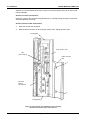
2.3
2. Product Data
MicroCubicle™ Dimensions
2. Product Data
A
TOP
VIEW
B
130O
max
310O
max
F
20 mm
DRAWING
NOT TO SCALE
FRONT
VIEW
C
Template drilling dimensions for
mounting are provided in
Section 3.5.
E
D
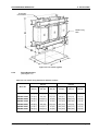
Figure 2-1 MicroCubicle™ dimensions
Table 2-3 MicroCubicle™ physical dimensions
Dimensions
mm (in)
Frame
Size
A
B
C
Weight
D
E
F (max)
kg (lb)
3
170 (6.7)
350 (13.8)
600 (23.7)
60 (2.37)
110 (4.33)
149 (5.9)
27(60)
4
255 (10.0)
370 (14.6)
789 (31.2)
145 (5.7)
110 (4.33)
204 (8.0)
45.5 (100)
6
430 (17.0)
420 (16.6)
873 (34.4)
320 (12.6)
110 (4.33)
316 (12.4)
100 (220)
7
485 (19.1)
450 (17.8)
1155 (45.5)*
372 (14.7)
110 (4.33)
350 (13.8)
155 (342)
* Overall height, including keypad harbour overhang
(06/06)
ALSPA MV3000e Getting Started Manual for AEM Drives
Page 2-3
2. Product Data
ALSPA MV3000e AEM Drives
2.4
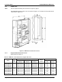
AC Line Reactor
Note:
This is a required ancillary item as shown in Figure 2, page iii.
The AC line reactor is constructed in two parts to allow the PWM filter to be connected
between them. These parts are designated /01 and /02, and are typically as shown in Figure
2-2. Part /02 is considerably larger than part /01. Physical dimensions are given in Tables 2-4
and 2-5, fixing dimensions are given in Table 2-6.
2.4.1
Physical Dimensions, Inductance and Losses
(See Figure 2-2)
Table 2-4 AC Line reactor (part /01) dimensions, inductance and losses
Overall Dimensions
Reactor
Part No.
Height A
mm (in)
Cable Fixing
Hole Dia.
Earth Stud
Lug
Weight
Inductance
Losses
mm (in)
kg (lb)
µH
W
Width B
mm (in)
Length C
mm (in)
mm (in)
400 V @ 50 Hz / 480 V @ 60 Hz
MV3SRL037A5/01
245 (9.65)
174 (6.85)*
240 (9.45)
Flying Leads
M6 (1/4)
22 (49)
583
170
MV3SRL075A5/01
295 (11.8)
180 (7.1)*
300 (11.8)
Flying Leads
M8 (5/16)
36 (79)
318
270
MV3SRL200A5/01
455 (17.9)
200 (7.9)
420 (16.5)
11 (0.43)
M8 (5/16)
110 (242)
126
450
MV3SRL315A5/01
465 (18.3)
210 (8.3)
390 (15.35)
13 (0.5)
M8 (5/16)
130 (286)
74
490
295 (11.6)
190 (7.48)*
300 (11.8)
Flying Leads
M8 (5/16)
36 (79)
638
280
MV3SRL200A7/01
455 (17.9)
200 (7.87)
420 (16.5)
11 (0.43)
M8 (5/16)
110 (242)
308
480
MV3SRL315A7/01
485 (19.1)
230 (9.1)
480 (18.9)
11 (0.43)
M8 (5/16)
160 (352)
180
540
Cable Fixing
Hole Dia.
Earth Stud
Lug
Weight
Inductance
Losses
600 V @ 60 Hz / 690 V @ 50 Hz
MV3SRL090A7/01
* Includes 30 mm for flying leads
Table 2-5 AC Line reactor (part /02) dimensions, inductance and losses
Overall Dimensions
Reactor
Part No.
Height A
mm (in)
Width B
mm (in)
Length C
mm (in)
mm (in)
mm (in)
kg (lb)
µH
W
400 V @ 50 Hz / 480 V @ 60 Hz
MV3SRL037A5/02
400 (15.8)
300 (11.8)*
360 (14.2)
Flying Leads
M10 (3/8)
78 (172)
1,749
335
MV3SRL075A5/02
515 (20.3)
310 (12.2)*
480 (18.9)
Flying Leads
M10 (3/8)
130 (286)
953
850
MV3SRL200A5/02
660 (26.0)
316 (12.5)
660 (26.0)
11 (0.43)
M12 (1/2)
280 (616)
379
2,400
MV3SRL315A5/02
765 (30.1)
362 (14.3)
720 (28.4)
13 (0.5)
M12 (1/2)
410 (902)
223
2,800
600 V @ 60 Hz / 690 V @ 50 Hz
MV3SRL090A7/02
515 (20.3)
380 (15.0)*
480 (18.9)
Flying Leads
M10 (3/8)
135 (297)
1,914
1,050
MV3SRL200A7/02
660 (26.0)
316 (12.5)
660 (26.0)
11 (0.43)
M12 (1/2)
280 (616)
923
2,050
MV3SRL315A7/02
755 (30.0)
362 (14.3)
720 (28.4)
11 (0.43)
M12 (1/2)
460 (1014)
537
3,200
* Includes 30 mm (1.2 in) for flying leads
Note:
Page 2-4
Flying leads are 1,000 mm (39 in) long.
ALSPA MV3000e Getting Started Manual for AEM Drives
(06/06)
ALSPA MV3000e AEM Drives
2. Product Data
Thermistor
Connections
Cable Fixing
Hole
Figure 2-2 Line reactor (typical)
2.4.2
Fixing Dimensions
(See Figure 2-2)
Table 2-6 Line reactor fixing dimensions (between centres)
Part /01
Part /02
Model No.
Width D
mm (in)
Length E
mm (in)
Hole dia.
mm (in)
Width D
mm (in)
Length E
mm (in)
Hole dia.
mm (in)
MV3SRL037A5
114 (4.5)
200 (7.9)
10 (0.4)*
230 (9.1)
120 (4.75)
11 (0.5)
MV3SRL075A5
120 (4.8)
204 (8.0)
10 (0.4)*
230 (9.1)
160 (6.3)
14 (0.6)
MV3SRL200A5
170 (6.7)
270 (10.7)
12 (0.5)
266 (10.5)
440 (17.4)
14 (0.6)
MV3SRL315A5
180 (7.1)
300 (11.8)
12 (0.5)
312 (12.3)
480 (18.9)
14 (0.6)
MV3SRL090A7
130 (5.2)
204 (8.0)
10 (0.4)*
300 (11.8)
160 (6.3)
14 (0.6)
MV3SRL200A7
170 (6.7)
270 (10.7)
12 (0.5)
266 (10.5)
440 (17.4)
14 (0.6)
MV3SRL315A7
190 (7.5)
320 (12.6)
14 (0.6)
312 (12.3)
480 (18.9)
14 (0.6)
* Slot width
(06/06)
ALSPA MV3000e Getting Started Manual for AEM Drives
Page 2-5
2. Product Data
ALSPA MV3000e AEM Drives
2.5
PWM Filter
Note:
This is a required ancillary item as shown in Figure 2, page iii.
The PWM filter for frame sizes 3 and 4 is shown in Figure 2-3. The filters for frame sizes 6 and
7 are shown in Figure 2-4.
Figure 2-3 PWM filter for frame sizes 3 and 4
2.5.1
Physical Dimensions and Losses
(See Figures 2-3 and 2-4)
Table 2-7 PWM filter, overall dimensions, weights and losses
Model
for
Frame
Size
MV3PWM071A5
Overall Dimensions
Losses
Weight
Height A
mm (in)
Width B
mm (in)
Depth C
mm (in)
Kg (lb)
Typical
W
Maximum
W
3
487.4 (19.2)
133.4 (5.3)
399.6 (15.8)
15 (33)
56
115
MV3PWM140A5
4
487.4 (19.2)
133.4 (5.3)
399.6 (15.8)
16 (36)
108
188
MV3PWM099A6
4
487.4 (19.2)
133.4 (5.3)
399.6 (15.8)
16 (36)
114
121
MV3PWM242A6
6
539.1 (21.3)
311.0 (12.3)
305.6 (12.0)
36 (84)
128
468
MV3PWM364A5
6
539.1 (21.3)
311.0 (12.3)
305.6 (12.0)
36 (84)
333
613
MV3PWM382A6
7
539.1 (21.3)
601.3 (23.7)
305.6 (12.0)
54 (119)
485
1018
MV3PWM566A5
7
539.1 (21.3)
601.3 (23.7)
305.6 (12.0)
54 (119)
520
1167
Page 2-6
ALSPA MV3000e Getting Started Manual for AEM Drives
(06/06)
ALSPA MV3000e AEM Drives
2. Product Data
Figure 2-4 PWM filter for frame size 6 or 7 (size 7 shown)
2.5.2
Fixing Dimensions
(See Figures 2-3 and 2-4)
Table 2-8 PWM filter fixing dimensions
Model
for
Frame
Size
MV3PWM071A5
Fixing Dimensions
D
mm (in)
E
mm (in)
F
mm (in)
G
mm (in)
H
mm (in)
J
mm (in)
Slot Width
mm (in)
3
13.0 (0.51)
464.4 (18.3)
16.4 (0.65)
55.0 (2.2)
–
–
6.0 (0.24)
MV3PWM140A5
4
13.0 (0.51)
464.4 (18.3)
16.4 (0.65)
55.0 (2.2)
–
–
6.0 (0.24)
MV3PWM099A6
4
13.0 (0.51)
464.4 (18.3)
16.4 (0.65)
55.0 (2.2)
–
–
6.0 (0.24)
MV3PWM242A6
6
13.7 (0.54)
514.4 (20.3)
119.6 (4.7)
170.8 (6.7)
119.6 (4.7)
280.8 (11.1)
7.0 (0.28)
MV3PWM364A5
6
13.7 (0.54)
514.4 (20.3)
119.6 (4.7)
170.8 (6.7)
119.6 (4.7)
280.8 (11.1)
7.0 (0.28)
MV3PWM382A6
7
13.7 (0.54)
514.4 (20.3)
119.6 (4.7)
341.6 (13.5)
119.6 (4.7)
451.6 (17.8)
7.0 (0.28)
MV3PWM566A5
7
13.7 (0.54)
514.4 (20.3)
119.6 (4.7)
341.6 (13.5)
119.6 (4.7)
451.6 (17.8)
7.0 (0.28)
(06/06)
ALSPA MV3000e Getting Started Manual for AEM Drives
Page 2-7
2. Product Data
ALSPA MV3000e AEM Drives
2.6
Fan Transformer
Note:
This is a required ancillary item as shown in Figure 2, page iii.
2.6.1
Physical Dimensions and Losses
(See Figure 2-5)
EARTH TERMINAL
A
OUTLINE OF
TERMINAL BLOCK
E
F
D
G
B
C
Figure 2-5 Fan transformer dimensions
Table 2-9 Fan transformer overall dimensions and losses
Overall Dimensions
Model
Weights
Losses
Height A
mm (in)
Width B
mm (in)
Length C
mm (in)
kg (lb)
W
MV3FTX0350A4
210 (8.3)
170 (6.7)
170 (6.7)
13 (5.9)
40
MV3FTX0750A4
210 (8.3)
220 (8.7)
170 (6.7)
21 (9.5)
60
MV3FTX1306A4
250 (9.9)
200 (7.9)
220 (8.7)
23 (10.5)
90
MV3FTX0350A6
210 (8.3)
170 (6.7)
170 (6.7)
13 (5.9)
40
MV3FTX0750A6
210 (8.3)
220 (8.7)
170 (6.7)
21 (9.5)
60
MV3FTX1306A6
250 (9.9)
200 (7.9)
220 (8.7)
23 (10.5)
90
Table 2-10 Fan transformer fixing dimensions
Page 2-8
Model
Centres
D
mm (in)
Centres E
mm (in)
Centres F
mm (in)
G
mm (in)
Slot Width
mm (in)
MV3FTX0350A4
119 (4.7)
89 (3.5)
75 (3.0)
91 (3.6)
7.0 (0.28)
MV3FTX0750A4
119 (4.7)
89 (3.5)
125 (4.9)
141 (5.6)
7.0 (0.28)
MV3FTX1306A4
–
114 (4.5)
100 (3.9)
127 (5.0)
9.5 (0.37)
MV3FTX0350A6
119 (4.7)
89 (3.5)
75 (3.0)
91 (3.6)
7.0 (0.28)
MV3FTX0750A6
119 (4.7)
89 (3.5)
125 (4.9)
141 (5.6)
7.0 (0.28)
MV3FTX1306A6
–
114 (4.5)
100 (3.9)
127 (5.0)
9.5 (0.37)
ALSPA MV3000e Getting Started Manual for AEM Drives
(06/06)
ALSPA MV3000e AEM Drives
2.6.2
2. Product Data
Electrical Data for Fan Transformer
Table 2-11 Fan transformer electrical data *
Secondary Fuses **
Continuous VA Ratings
Model
Fan
(230 V)
A
Auxiliary
(110 V)
A
@
230 V
@
110 V
MV3FTX0350A4
1
6
172.5
177.5
MV3FTX0750A4
2
10
460
290
MV3FTX1306A4
7
12.5
920
386
MV3FTX0350A6
1
6
172.5
177.5
MV3FTX0750A6
2
10
460
290
MV3FTX1306A6
7
12.5
920
386
A4 products have primary tappings at 380 – 400 – 415 – 440 – 480 V
A6 products have primary tappings at 500 – 525 – 600 – 660 – 690 V
*
**
2.7
For primary fuse ratings see Section 2.2, for fuse types see Section 3.6.1.
Supplied fitted internally, type T fuses, 32 mm x 6.35 mm (1¼ in x ¼ in).
Line Contactor LCN
The main contacts of LCN should be rated for the mains current for the relevant voltage grade
shown in Table 2-2 against each mains bridge type.
To use the standard fan transformer, the LCN coil must be rated for 110 VAC and must be
within the VA rating of the 110 V winding of the fan transformer, refer to
Table 2-11 above.
As an example, part numbers for suitable Telemecanique contactors are given
in Table 2-12.
Table 2-12 Line Contactor LCN – rating of main contacts and suitable example
Part Numbers for Telemecanique (example contactor)
Converter
Contactor
type
Rating
Standard
AC1
Rating (A)
55 C UL
MV3071J5A1
LC1-D5011F7
LC1-D6511F7
IEC
UL/CSA
80
80
MV3140J5A1
LC1-D11500F7
LC1-F115
IEC
UL/CSA
200
MV3364J5A1
LC1-F400
LC1-F400
IEC
UL/CSA
MV3566J5A1
LC1-F500
LC1-F500
MV3099J6A1
70
80
Coil
type
Auxiliary
contacts
–
–
–
–
RC
Suppressor
Suppressor
bracket
Set of 6
shrouds
LA4-DA2G
LA4-DA2G
–
–
–
–
–
LA-D09981
–
LA9-F701
175
–
LX1-FF110
LA1D
LA1-DN11
LA4-DA
LA9-F980
430
430
420
420
LX1-FJ110
LX1-FJ110
LA1-DN11
LA1-DN11
LA9-D09980
LA9-D09980
LA-D09981
LA-DO9981
LA9-F703
LA9-F703
IEC
UL/CSA
580
580
700
700
LX1-FK110
LX1-FK110
LA1-DN11
LA1-DN11
LA9-D09980
LA9-D09980
LA-D09981
LA-D09981
LA9-F703
LA9-F703
LC1-D8011F7
LC1-D8011F7
IEC
UL/CSA
125
125
110
110
–
–
MV3242J6A1
LC1-F185
LC1-F265
IEC
UL/CSA
275
300
200
285
LX1-FG110
LX1-FJ110
LA1-DN11
LA1-DN11
LA9-F980
LA9-F980
LA-D09981
LA-D09981
LA9-F702
LA9-F703
MV3382J6A1
LC1-F400
LC1-F400
IEC
UL/CSA
430
430
420
420
LX1-FJ110
LX1-FJ110
LA1-DN11
LA1-DN11
LA9-D09980
LA9-D09980
LA-D09981
LA-D09981
LA9-F703
LA9-F703
(06/06)
–
–
LA4-DA2G
LA4-DA2G
ALSPA MV3000e Getting Started Manual for AEM Drives
–
–
–
–
Page 2-9
2. Product Data
ALSPA MV3000e AEM Drives
2.8
Electrical and Environmental Specifications
2.8.1
Common Specifications
Table 2-13 Environmental data
–
Temperature range
o
o
o
o
–25 C to +55 C (–13 F to +130 F)
–
Relative humidity
5% to 95%, non-condensing
–
Altitude
Not critical below 40 o C (104o F)
Temperature range
o
o
o
o
–25 C to +70 C (–13 F to +158 F)
–
Relative humidity
≤ 95%, non-condensing
–
Altitude
Not critical below 40 o C (104o F)
–
Vibration, drop
IEC 60721-3-2 Class 2M1
Operating –
Altitude (max.)
1000 m, 1000 m to 2000 m with derating, Refer to Section 2.1
–
Temperature range
0o C to 40o C (+32o F to +104o F); 40o C to 50o C (+104o F to
+122o F) with derating, Refer to Sections 2.1 and 2.2
–
Relative humidity
5% to 95%, non-condensing
–
Vibration
IEC 60721-3-3 Class 3M1 & EN50178
–
Cooling air
(pollution and dust)
Pollution Degree 2 (IEC 60664-1, UL 840, CSA C22.2 No. 0.293) i.e. clean, free from dust, condensation and conductive or
corrosive gases. If optional dirty air kit is fitted, the main
heatsink can be exposed to unfiltered air that does not contain
corrosive, conductive or explosive dust or gases.
Storage
Transport –
Ingress protection
2.8.2
IP20, (NEMA 1). Ancillary items are IP00 (unprotected)
IP21 with Drip Option
Specifications for Machine Bridges
Table 2-14 Electrical data for Machine Bridges
Supply
–
Voltage range *
450 V – 850 VDC, for 400 V 50 Hz or 480 V 60 Hz nominal outputs
600 V – 1100 VDC, for 600 V 60 Hz nominal output
600 V – 1140 VDC, for 690 V 50 Hz nominal output
Insulation –
UL 840, CSA C22-2 No. 0.2, EN 50178:
TN or TT network: Overvoltage Category lll
IT network: Overvoltage Category ll
For full compliance with UL 508C, transient suppressors complying
with UL 1449 must be fitted external to the drive.
Switching frequency (default)
1.25 kHz for all Machine Bridges.
Output
50% or 10% for one minute, as selected, with a maximum of six
equally spaced overloads in any hour.
–
*
Page 2-10
Overload current
These DC supply voltages are absolute limits. If there is ripple
on the supply, it must not cause excursions outside these limits.
ALSPA MV3000e Getting Started Manual for AEM Drives
(06/06)
ALSPA MV3000e AEM Drives
2.8.3
2. Product Data
Specifications for Sinusoidal Front End (SFE)
Table 2-15 Electrical data for SFE
Supply
–
Standard voltage
range (as selected)
380 V – 440 V (400 V nominal), 50 Hz
500 V – 690 V (690 V nominal), 50 Hz
440 V – 480 V (480 V nominal), 60 Hz
500 V – 600 V (600 V nominal), 60 Hz
–
Voltage variation
(on voltage range)
±10% long term, ±15% for 0.5 to 30 cycles with loss of
performance but no trip
–
Voltage unbalance
Negative sequence voltage 3%
–
Frequency
(optimised)
50 Hz, 60 Hz, as selected
–
Operational
frequency range
45 Hz to 63 Hz.
–
Network type
TN or TT (earthed/grounded neutral).
Can also be connected to IT network (i.e. isolated neutral) if IT
network is separated from public mains supply by an isolating
transformer.
–
Notching
immunity
Immunity to commutation notches up to 40% as defined
by IEC 60164-1-1
Insulation –
UL 840, CSA C22-2 No. 0.2, EN 50178:
TN or TT network: Overvoltage Category lll
IT network: Overvoltage Category ll
For full compliance with UL 508C, transient suppressors
complying with UL 1449 must be fitted external to the drive.
Switching –
frequency
Default
2.5 kHz for all SFE.
Output
Overload current
50% or 10% for one minute, as selected, with a maximum of
six equally spaced overloads in any hour.
–
2.9
Product Performance Data
2.9.1
Product performance data for Machine Bridges
Table 2-16 Product performance data for Machine Bridges
Frequency –
Speed
Resolution
0.01%
–
Control accuracy
0.1%
–
Resolution
0.01%
–
Accuracy (absolute)
0.01%
VVVF
ENCODERLESS
FLUX VECTOR
FLUX VECTOR
WITH ENCODER
50 : 1
50 : 1
>1000 : 1
Speed Control Bandwidth
N/A
20 Rad/s
100 Rad/s
Torque Control Bandwidth
< 1 Rad/s
> 500 Rad/s
> 500 Rad/s
Torque Control Accuracy
≅ 10 %
≅ 10 %
≅5%
Speed Control Accuracy
≅1%
≅ 0.5 %
≅ 0.02 %
Speed Control Range
(06/06)
ALSPA MV3000e Getting Started Manual for AEM Drives
Page 2-11
2. Product Data
2.9.2
ALSPA MV3000e AEM Drives
Product performance data for Sinusoidal Front End
Table 2-17 Performance data for Sinusoidal Front End
DC link voltage control
AC current control
2.9.3
–
Resolution
1V
–
Accuracy
±1%
–
Bandwidth
200 rad/s
–
Resolution
0.01% rated current
–
Accuracy
±1%
–
Bandwidth
>500 rad/s
Mains Impedance
The SFE produces currents at the switching frequency and its harmonics. The PWM filters
listed in Section 2.5 are used to reduce the switching frequency currents injected into the
mains supply and thus prevent damage to other equipment.
The PWM filter is designed to enable the SFE to comply with voltage harmonic performance
limits (class 3 supplies) of 1% of fundamental for any individual frequency and 1.5% for the
rms sum of individual frequencies in any 200 Hz band at the in-plant point of common
coupling. This is achieved when the SFE is operated with a mains supply having a fault level
equal to or greater than the value shown in Table 2-18 for each product.
Table 2-18 Mains supply minimum fault levels
Page 2-12
MV3000e
Product
Minimum Fault Levels
for compliance with
Voltage Distortion Specification
MVA
MV3071J5A1
13
MV3140J5A1
25
MV3364J5A1
13
MV3566J5A1
20
MV3099J6A1
26
MV3242J6A1
13
MV3382J6A1
20
ALSPA MV3000e Getting Started Manual for AEM Drives
(06/06)
ALSPA MV3000e AEM Drives
2.10
2. Product Data
DC Link Overvoltage Trip Levels
The SFE will attempt to maintain accurate control of the DC link voltage under all conditions.
However, a shock load to the motor can cause a disturbance of the DC voltage. The DC link
overvoltage trip levels for the J5 and J6 series products covered by this manual are shown in
Table 2-19.
Table 2-19 DC link overvoltage trip levels
Nominal AC Voltage
Overvoltage
Trip Setting
2.11
J5 series
J6 series
400 V/480 V
600 V/690 V
868 V – 891 V
1155 V – 1184 V
Acoustic Noise Levels
The maximum acoustic noise levels generated by the products covered in this manual are
shown in Table 2-20 and 2-21.
Table 2-20 Acoustic noise generated by bi-directional converters
Frame size
Maximum noise level 1.0 m (39.4 in) in
any direction from converter
dBA
3
70 *
4
66
6
73 *
7
80 *
* Refer to WARNING in Sections 3.5, 5A and 5B.
Table 2-21 Acoustic noise generated by PWM filter fans
PWM filter
Maximum noise level 1.0 m (39.4 in)
in any direction from PWM filter
dBA
MV3PWM071A5
MV3PWM140A5
30
MV3PWM099A6
MV3PWM242A6
MV3PWM364A5
MV3PWM382A6
MV3PWM566A5
(06/06)
61
62.5
ALSPA MV3000e Getting Started Manual for AEM Drives
Page 2-13
2. Product Data
2.12
ALSPA MV3000e AEM Drives
Standards
The ALSPA MV3000e AEM product complies with the standards listed below.
Safety
EN 50178
Electronic equipment for use in power installations.
ANSI / UL508C
Power conversion equipment.
CAN / CSA C22.2-14
Industrial control equipment, industrial products.
Electromagnetic Compatibility (EMC)
EN 61800-3
(IEC 61800-3)
Adjustable speed electrical power drive systems:
Part 3 – EMC product standard including specific
test methods.
In particular, this includes the following immunity requirements:
IEC 61000-4-2
Electrostatic discharge
6 kV contact discharge
8 kV air discharge
IEC 61000-4-3
Electromagnetic field
20 MHz – 1 GHz, 10 V/m
IEC 61000-4-4
Electrical fast
transient/burst
2 kV
IEC 61000-4-5
Surge
1 kV line-line
2 kV line-earth
Ratings/Performance
EN 61800-2
(IEC 61800-2)
Adjustable speed electrical power drive
systems:
Part 2 – General requirements - Rating specifications for low
voltage adjustable frequency power drive systems.
EN 60146-1-1
(IEC 60146-1-1)
Page 2-14
Semiconductor converters. General requirements
and line commutated converters.
ALSPA MV3000e Getting Started Manual for AEM Drives
(06/06)
ALSPA MV3000e AEM Drives
3. Installation
3. Installation
3.1
Introduction
This section covers everything which should be considered for the successful installation of a
basic ALSPA MV3000e AEM drive, to ensure long and trouble-free operation. The AEM drive
considered here is a Sinusoidal Front End (SFE), comprising a bi-directional converter used
as a mains bridge, feeding an identical bi-directional converter connected as a machine
bridge. The procedures given here will also enable the easy installation of other
configurations.
Figure 3-1 gives a simple overview of the installation procedure.
Section 3.2
Receiving and
storage
information,
including long
term storage
Section 3.1
Introduction to
Section 3
Section 3.4
A typical cabinet
layout, showing all the
considerations
needed for the sound
EMC installation
of an example AEM
drive
Section 3.3
Information
and
equipment to
help with EMC
and harmonic
distortion
Sections 3.10 to 3.15
Sections 3.6 to 3.9
Continue to
Sections 4, 5A, 5B
(Commissioning)
Instructions for
the electrical
installation of
frame sizes
3 to 7
General
electrical
installation
requirements,
including fuses,
cable lugs,
cable selection
and encoders
Section 3.5
Mechanical
installation,
including
positioning and
mounting of the
products, and all
environmental
considerations
Figure 3-1 Installation overview
3.2
Receipt of Equipment
3.2.1
Inspection and Storage
Check the contents of the complete consignment against the Delivery Note for any damage,
shortages or loss in transit. If any item is found to be damaged or missing, contact
Converteam at the address/telephone number shown at the end of this manual, quoting the
following details:
• List of damaged or missing items with names and part numbers.
• Description of damage.
• Delivery Note numbers and dates, and order and item numbers.
If the product is not to be installed immediately:
• Re-pack it in its original packaging material. If this is not possible it should be enclosed in
polythene sheet to protect it from the ingress of dust.
• Store it in a clean, dry atmosphere, preferably at room temperature, ensuring that the
storage environment meets the requirements of Section 2.8.
• The product can be stored indefinitely at normal room temperature without the need to reform the DC link capacitors before use.
• If the product is unpacked in a warm environment condensation may occur.
Should condensation be seen, the converter should not be used until its temperature has
stabilised to that of the working environment.
(06/06)
ALSPA MV3000e Getting Started Manual for AEM Drives
Page 3-1
3. Installation
ALSPA MV3000e AEM Drives
Note:
PWM filter modules MV3PWM071A5, MV3PWM140A5 and MV3PWM099A6 should not be
left unsupported in an upright position. When not in use, they should be laid on their left hand
face (when viewed from the front).
3.2.2
Handling
Lifting points incorporating holes for shackles are fitted to the top of each MicroCubicle™. The
lifting points are flush with the case and pull out when required.
WARNING
Items marked with weights greater than 20 kg should only be moved with lifting
apparatus.
Frame size 7 converters are fitted with extra lifting points underneath, so they can be lifted
with the doors facing upwards.
A suggested method of lifting is shown in Figure 3-2; use shackles which are suitable for the
weight of the MicroCubicle™ (see Section 2.3).
FRAME SIZE
6
FRAME SIZE
3
FRAME SIZE
7
Lifting points for size 3,
4 and 6 have 10 mm
(0.4 in) holes
Lifting points for
size 7 have
16 mm (0.63 in)
holes
FRAME SIZE
4
y
For frame size 6 a spreader bar
must be used to obtain a vertical
lift, as shown (not to scale). For
frame size 7 the use of a spreader
bar, as shown, is recommended.
Figure 3-2 Lifting a MicroCubicleTM
Page 3-2
ALSPA MV3000e Getting Started Manual for AEM Drives
(06/06)
ALSPA MV3000e AEM Drives
3.3
Harmonic Recommendations
3.3.1
AC Line Reactors
3. Installation
When the bi-directional converter is configured as a mains bridge, it must be used with
ancillary components to form a Sinusoidal Front End, as shown in Figure 2 at the front of this
manual. The input AC line reactors (part /01 and part /02) are mandatory functional elements
and must be fitted. In conjunction with the PWM filter they reduce the harmonics generated by
the SFE. Types and specifications are given in Section 2.
The line reactors are fitted with thermistors to protect them against overheating in the event of
malfunction. The thermistors in reactors part /01 and /02 should be wired in series as shown in
Figure 2 and connected to the converter PTC input.
3.3.2
PWM Filters
The 3-phase PWM filter functions in conjunction with the AC line reactor to prevent the
MV3000e PWM switching frequency and its harmonics from being impressed on the mains
supply. The PWM filter must not be used for any other purpose.
The PWM filter is required to achieve compliance with the distortion specification in Section
2.9.3. It is connected as shown in Figure 2 on Page iii at the front of this manual. The filter is
enclosed and is force-cooled to prevent overheating.
The filter connections are fused to protect the filter and cables in the event of filter malfunction.
The fuse indicator switch is wired back into the interlock circuit to shut down the converter.
Note:
The various units have slightly different circuit configurations of resistors and capacitors.
Failure of a component within a unit may or may not blow fuses.
In the cases where a component failure does not cause fuses to blow, the filter would provide
some filtering depending on which component had failed. In some cases there would still be a
degree of filtering between all three phases, while in others there would be filtering only
between one pair of phases.
The result would be that more PWM ripple than normal could be imposed on the mains
supply. See Section 6 for details of monthly protective maintenance checks on PWM filters.
A thermostat is fitted within the PWM filter to protect against excessive overheating. This is
wired to the converter interlock in series with the PWM filter fuse indicator switch, so that if the
filter temperature is excessive the converter will shut down to prevent damage. The thermostat
is rated at 240 V, 10 Amps AC.
Mechanical and electrical data for the PWM filters is given in Section 2.5. Details of typical
fuse holders with integral "fuse blown" indicators are provided in Section 3.6.
3.4
EMC Recommendations
The ALSPA MV3000e AEM drive products comply with the requirements of IEC 61800-3
(EN 61800-3), EMC product standard for power drive systems, provided that they are installed
and used in accordance with the instructions in this manual.
EMC filters are not normally required for use in the industrial environment (“second
environment” according to IEC 61800-3).
For compliance with the limits of EN 50081-2 or the Class A limits of CISPR 11 or the “first
environment” limits of IEC 61800-3, an EMC filter is fitted between the mains network and the
AC line reactor part /01, as shown in Figure 2 at the front of this manual.
3.4.1
EMC Filter and Capacitors
EMC capacitors and an EMC filter may optionally be fitted.
(06/06)
ALSPA MV3000e Getting Started Manual for AEM Drives
Page 3-3
3. Installation
ALSPA MV3000e AEM Drives
EMC filtering will be required if the mains bridge is installed on a public low voltage supply
which also supplies domestic premises (“first environment” according to IEC 61800-3).
Filtering will also be required if other items connected to the same supply are sensitive to radio
frequency interference or would normally be used in domestic environments.
EMC filtering may only be used if the supply neutral is connected to earth (ground) at the
source of the supply (also known as TN or TT network).
If EMC filters are to be used and there are also thyristor converters (e.g. DC drives) on the
same network, any commutation notches from these converters must not exceed 40% depth.
Refer to the AEM MicroCubicle™ buyers' guide for details.
3.4.2
Cabinet Layout for EMC Compliance
The layout for a typical cabinet installation of an AEM drive, for EMC compliance, is shown in
Figure 3-3. Wiring should obey the following segregation rules where possible:
1.
Power input and output wiring must be separated by ≥300 mm (12 in).
2.
Control and power wiring must be separated by ≥300 mm (12 in) except when
crossing, which must be at 90o.
3.
If an EMC filter is fitted, cables on the input side of the filter must be separated from
cables and components on the drive side of the filter (e.g. AC line reactor from input
cables).
The mains bridge, ancillary components and machine bridge must be mounted in the same
metallic enclosure. If, due to size constraints this is not possible, the enclosures should be
metallically bonded to each other or connected via screened cable or conduit.
If an EMC filter is fitted, it must be in direct metallic contact with the panel on which the bidirectional converters are mounted. The gland for the motor cable screen must also have a
direct metallic contact to this panel.
Note:
Figure 3-3 is a mechanical representation. Refer to Figure 2 at the front of this manual for the
electrical interconnection diagram, including motor earthing (grounding) and bonding etc.
The layout shown in Figure 3-3 is suitable for smaller size systems, with only the line reactor
(part /02) floor mounted. Larger systems have other large auxiliary components which may
also require floor mounting.
Page 3-4
ALSPA MV3000e Getting Started Manual for AEM Drives
(06/06)
ALSPA MV3000e AEM Drives
3. Installation
Auxiliary Fuses
Pre-charge supply
Fan
Transformer
Fan Transformer Primary Fuses
230 V Fan supply
CLOSE LCN
DC Link
Customer
110 V
supply
AC Line Reactor
(part /01)
PWM Filter
Fuses/Indicator
MV3000
LOAD
LINE
MV3000
Mains Bridge
Interlock
EMC filter
(if fitted)
Machine Bridge
Ø300 mm
(12 in)
Ø300 mm
(12 in)
Main
fuses
PWM filter
Interlock
Control
wiring
Ø300 mm
(12 in)
Thermistor
Suppressor
Isolator
(Disconnect)
Ferrite
Assembly
(if fitted)
Contactor
LCN
AC Line Reactor
(part /02)
Cabinet Boundary
Optional
(see Section 9)
Mains
Network
Gland
(Bonds cable screens (shields)
to cabinet)
M
Figure 3-3 Typical cabinet layout for EMC compliance
(06/06)
ALSPA MV3000e Getting Started Manual for AEM Drives
Page 3-5
3. Installation
3.5
ALSPA MV3000e AEM Drives
Mechanical Installation
WARNING
All items exposing high voltage must be placed in a suitable enclosure with restricted
access.
Note:
A list of ancillary items exposing high voltage is given in Section 3.15.
WARNING
3.5.1
•
Air used to cool the product is unfiltered. Air ejected from the product may contain
foreign particles. Air outlets should deflect the air away from the eyes.
•
The combined audible noise emitted by fans in an installation can be greater than
70 dB(A), dependent on the air flow path.
Measure the audible noise level in the installation.
When the audible noise level exceeds 70 dB(A), appropriate warning notices should
be displayed.
•
Items marked with weights greater than 20 kg should only be moved with lifting
apparatus.
Cooling and Environment
Cooling
The heat loss under 1.1/1.5 overload conditions, and typical
airflow requirement for each product, including the
associated AC line reactors, are shown in Section 2. The
effect of these losses must be considered when choosing a
location for the drive or when selecting a cabinet. A typical
airflow arrangement is shown in Figure 3-4.
Canopy to prevent
ingress of water etc.
If optional equipment is installed, heat losses for these items
must also be considered; these losses can be found in the
associated manuals.
Drive
extractor fans
All converters comply with the requirements for Pollution
Degree 2 according to IEC 60664-1, UL 840 and
CSA C22.2 No. 0.2-93. Therefore the cooling air must
comply with the requirements of Section 2.8, which includes
requirements where a dirty air kit is to be fitted.
Top
MV3000
Environment
Bottom
All bi-directional converters comply with IP20 and NEMA 1.
They must be protected from dripping liquids either by use of
a suitable enclosure or by the use of a protective canopy
available from Converteam.
The operating environment must comply with the
requirements in Section 2.8.
Clean
airflow
If conductive pollution or condensation are expected
(Pollution Degree 3), the drive must be placed in an
enclosure which achieves Pollution Degree 2 by:
Page 3-6
•
Excluding the conductive pollution e.g. by the use of
filtered air
•
Preventing condensation e.g. by the use of anticondensation heaters.
Figure 3-4 Typical airflow
arrangement
ALSPA MV3000e Getting Started Manual for AEM Drives
(06/06)
ALSPA MV3000e AEM Drives
3. Installation
Noise Levels
B
A
A
The maximum acoustic noise levels generated
by ALSPA MV3000e converters are shown in
Section 2.11.
C
3.5.2
Clearances and Mounting Distances
The minimum acceptable clearances for
Converter outline
(not to scale)
100 mm
(4 in)
D
Cabinet boundary or
next row of ALSPA
MV3000 converters,
AC line reactors or
filters
Studs/Bolts all
size M8 (5/16 in.)
grade 8.8
75 mm
(3 in)
E
See Figure 2-1 for
maximum clearance
with door open
(See
Note in
Section
3.5.2)
Figure 3-6 Bolt/stud locations for mounting the
converter on a panel
ventilation are shown in Figure 3-5.
Note:
The 75 mm (3 in) clearance from the
100 mm
left hand side of the cabinet allows
0 mm
(4 in)
for easy access to control wiring,
however as the control connections
are 2-part and can be separated to
facilitate connection of wiring, then this clearance can be reduced to zero.
3.5.3
Mounting Checklist
Cabinet boundary or
next row of ALSPA
MV3000 converters,
AC line reactors or
filters
Figure 3-5 Minimum recommended clearances
When mounting the product the
following five items should be considered, in the order shown:
(06/06)
1.
The position of mounting studs/bolts for all converter frame sizes are shown in Figure
3-6 and Table 3-1. If “dirty air” ventilation is to be used with cabinet mounting, allow
space for ducting cut-outs in the panel, above and below the converter. See step (2).
2.
The size, weight and fixing dimensions of auxiliary components are given in Section 2.
Most of these components can be mounted on a metal component panel with the
converter. For larger frame sizes the line reactor (part /02) may be more suited to floor
mounting, due to its weight.
3.
If a dirty air kit is to be installed for high IP grades (e.g. IP54), read the instructions
provided with the kit before mounting the converter.
4.
Install any required options that fit inside the MicroCubicle™. Installation instructions
are provided in the associated publications – refer to Section 9 for available options
5.
Mount the converter and ancillary components in the cabinet.
ALSPA MV3000e Getting Started Manual for AEM Drives
Page 3-7
3. Installation
3.6
ALSPA MV3000e AEM Drives
Electrical Installation - General
This section contains details on
connecting an AEM drive,
comprising a SFE connected to a
machine bridge, for a basic
application. Details include:
•
•
•
Table 3-1 Position of mounting studs/bolts
Dimension
mm (in)
Fuse ratings, cable sizes and
selection.
Power wiring, mains network
and DC link wiring, torque
settings.
Control wiring, for control and
monitoring.
Frame Size
3
4
6
7
A
35
(1.4)
40
(1.6)
38
(1.5)
47
(1.85)
B
100
(3.9)
175
(6.8)
354
(13.9)
390
(15.4)
C
12
(0.47)
12
(0.47)
20
(0.8)
12
(0.47)
D
578
(22.8)
766
(30)
838
(33.0)
1124
(44.3)
E
10
(0.4)
11
(0.4)
15
(0.6)
15
(0.6)
Maximum length of studs
A protruding from mounting
t panel is 25.4 mm (1 in)
t
he front of this manual a simple wiring diagram (Figure 1) and a brief description of
input/output (I/O) (Table 1) are located, together with the interconnection diagram of a typical
AEM drive (Figure 2).
3.6.1
Protection devices
WARNING
High leakage current
This equipment and the driven motor(s) must be earthed (grounded).
CAUTION
Ensure that all conductors connected to this equipment are mechanically
restrained.
Product Isolation
The AEM drive must be connected to the mains network via an isolator (disconnect).
The isolator should be rated to carry full load input current, and 1.1 or 1.5 x full load input
current (as selected) for 60 seconds, (see Section 2.2).
If auxiliary supplies (digital outputs, fan supplies) are not fed from this isolator, the isolator for
these supplies must be clearly identified.
Recommended Fuses
Section 2.2 gives the current rating of fuses recommended to protect the power and auxiliary
cables connected to the mains network. Section 2.6.2 gives the current rating of fuses
recommended to protect the cables connected to the primary of the fan transformer. The fuses
are shown in two utilisation categories:–
Page 3-8
IEC rating - Use general purpose fuses
class gG or gL according to
IEC 60269 and European
standards
Examples - GE Redspot to BS88
- Bussmann gG to BS88
- Bussmann with part numbers
NH.....G
UL rating - Use general purpose class
RK1 fuses according to UL
Examples - Bussmann LPS_RK_SP
- Bussmann LPJ_SP
ALSPA MV3000e Getting Started Manual for AEM Drives
(06/06)
ALSPA MV3000e AEM Drives
3. Installation
248-12, or class J fuses
according to UL 248-8
These fuses may not prevent damage to the inverter in the event of short circuits on the
DC link and other components.
When choosing fuses for a specific application, the user must also comply with local safety
regulations.
PWM Filter Fuses
The PWM filter fuses protect the filter under fault conditions. Ratings for the fuses are given in
Section 2, Table 2-2.
While these fuses have the utilisation categories given above, they must be monitored by a
normally closed blown fuse indicator wired into the mains bridge interlock line (see Section
3.3.2). This may be achieved by either:
•
striker pin fuses in a special fuseholder.
Example:
Ferraz Shawmut "French ferrule" gG fuse with striker in a Ferraz Shawmut
CMS fuse block with trip indicator;
OR
•
by connecting a fuse monitoring breaker across the fuses.
Example:
3.6.2
Siemens 3RV3611-0BD10 fuse monitoring breaker.
Cable Lugs and Recommended Torque Settings
Copper or plated copper cable lugs may be used. Table 3-2 shows the size of suitable studs
for each frame size, and gives recommended cable lug sizes and torque settings.
Table 3-2 Suitable stud sizes, cable lugs and torque settings
Torque Settings
Frame Size
Stud Size
Use Lug Size
3
M6
M6 or 1/4 in.
8
4
M8
M8 or 5/16 in.
15
130
6
M10
M10 or 3/8 in.
30
265
7
M12
M12 or 1/2 in.
45
400
Nm
3.7
lbf in
70
Cable Selection
All cables must have copper conductors.
Cable sizes must comply with local safety regulations.
Power cables are annotated c and g in the interconnection diagram Figure 2, at the front of
this manual. Cables rated 70°C (158°F) to 120°C (248°F) can be used. Converters rated
below 100 A mains or motor current (frame size 3 and some in frame size 4) can also accept
cables rated at 60°C (140°F).
(06/06)
ALSPA MV3000e Getting Started Manual for AEM Drives
Page 3-9
3. Installation
ALSPA MV3000e AEM Drives
Cables annotated d to f, h and i in Figure 2 can be rated 60°C (140°F) to
90°C (194°F). However, the PWM filter can also accept cables rated 120°C (248°F).
3.7.1
AC Power Cable Selection
AC power cables are annotated c on the interconnection diagram Figure 2.
Table 3-3 shows the maximum permitted and typical cable sizes for each converter.
In the table, converters are grouped by voltage grade as given in Sections 2.1 and 2.2.
The cable data shown for each voltage grade is valid for that voltage grade only. The typical
cable sizes are based on the following conditions:
•
Metric cable sizes for single core or multicore copper cable with 70°C (158°F) PVC
insulation, clipped to a surface in air, in a 30°C (86°F) ambient, based on
IEC 60364-5-523. These sizes are also suitable for steel wire-armoured cable according
to BS 7671, or NYCWY cable according to VDE 0276-603 installed in the same
conditions.
•
USA/Canadian cable sizes for copper conductors with 75°C (167°F) insulation in a
raceway or cable in a 30°C (86°F) ambient, based on NFPA 70-1999.
Table 3-3 AC Power cable sizes for SFE power wiring and for motor connection to machine bridges
Max. Permitted Cable
Sizes
(Physical Limitation)
Drive
Frame
Size
Metric
Sizes
2
mm
Typical Sizes
(1.1 overload duty)
AWG/MCM
Sizes
AWG
MCM
Metric
Sizes
2
mm
Typical Sizes
(1.5 overload duty)
AWG/MCM
Sizes
AWG
MCM
Metric
Sizes
2
mm
AWG/MCM
Sizes
AWG
MCM
400 V
MV3071J5A1
3
50
1
-
25
3
-
16
4
-
MV3140J5A1
4
95
4/0
-
70
2/0
-
50
1/0
-
MV3364J5A1
6
2x240
-
2x500
240
-
MV3566J5A1
7 (Note 1)
2x300
-
2x600
2x240
3
50
1
4/0
2x300
(Note 2)
185
-
500
2x185
-
2x500
16
6
480 V
MV3071J5A1
-
25
4
-
-
MV3140J5A1
4
95
50
2/0
-
35
1
-
MV3364J5A1
6
2x240
-
2x500
185
-
500
120
-
350
MV3566J5A1
7
2x300
-
2x600
2x185
-
2x500
2x185
-
2x400
600 V
MV3099J6A1
4
95
35
1
-
25
3
-
MV3242J6A1
6
2x240
4/0
-
2x500
-
120
-
350
95
-
250
MV3382J6A1
7
2x300
-
2x600
240
-
2x350
240
-
2x300
(continued)
690 V
MV3099J6A1
4
95
-
35
2
MV3242J6A1
6
2x240
-
2x500
120
300
95
4/0
MV3382J6A1
7
2x300
-
2x600
240
2x300
185
Page 3-10
4/0
-
35
1
ALSPA MV3000e Getting Started Manual for AEM Drives
500
(06/06)
ALSPA MV3000e AEM Drives
3. Installation
Max. Permitted Cable
Sizes
(Physical Limitation)
Drive
Frame
Size
Metric
Sizes
2
mm
Typical Sizes
(1.1 overload duty)
AWG/MCM
Sizes
AWG
MCM
Metric
Sizes
2
mm
Typical Sizes
(1.5 overload duty)
AWG/MCM
Sizes
AWG
MCM
Metric
Sizes
2
mm
AWG/MCM
Sizes
AWG
MCM
Note 1:
Alternatively, busbars may be connected to frame size 7 drives. The maximum permitted busbar sizes are:
AC connections:
51 mm x 6.4 mm (2" x ¼")
DC connections:
76 mm x 6.4 mm (3" x ¼")
When busbars are used the fingerguard must be removed and the installer must provide alternative
protection against contact with live parts.
Note 2:
Cables rated according to the above rules are too large for this connection. Use high temperature cables
or busbars.
3.7.2
DC Link Cable Selection
DC link cables are annotated g on the interconnection diagram, Figure 2 (Page iii).
Note:
To minimise circuit inductance and radiated noise, the DC+ and DC– cables must be bound
together.
Table 3-4 shows maximum permitted and typical DC link cable sizes for each converter. In the
table, converters are grouped by order of AC voltage grade as given in Sections 2.1 and 2.2.
The cable data shown for each voltage grade is valid for that voltage grade only.
The cable rating conditions are the same as detailed for AC power cable selection in
Section 3.7.1.
Table 3-4 DC link cable sizes
Max. Permitted Cable
Sizes
(Physical Limitation)
Drive
Frame
Size
Metric
Sizes
2
mm
Typical Sizes
(1.1 overload duty)
AWG/MCM
Sizes
AWG
MCM
Metric
Sizes
2
mm
Typical Sizes
(1.5 overload duty)
AWG/MCM
Sizes
AWG
MCM
Metric
Sizes
2
mm
AWG/MCM
Sizes
AWG
MCM
400 V
MV3071J5A1
3
50
1
-
25
2
-
16
3
-
MV3140J5A1
4
95
4/0
-
70
4/0
-
35
2/0
-
MV3364J5A1
6
2x240
-
2x500
2x120
185
-
MV3566J5A1
7 (Note 1)
2x300
-
2x600
2x240
MV3071J5A1
3
50
1
-
16
2
-
16
4
-
MV3140J5A1
4
95
4/0
-
50
3/0
-
35
1/0
-
MV3364J5A1
6
2x240
-
2x500
185
-
150
-
MV3566J5A1
7
2x300
-
2x600
2x185
-
2x500
(Note 2)
2x150
2x350
(Note 2)
480 V
2x350
(Note 2)
2x150
2x250
(Note 2)
(continued)
600 V
MV3099J6A1
4
95
35
2/0
25
1
-
MV3242J6A1
6
2x240
-
4/0
2x500
-
150
-
2x250
-
95
-
400
MV3382J6A1
7
2x300
-
2x600
2x120
-
2x600
240
-
2x500
690 V
(06/06)
ALSPA MV3000e Getting Started Manual for AEM Drives
Page 3-11
3. Installation
ALSPA MV3000e AEM Drives
Max. Permitted Cable
Sizes
(Physical Limitation)
Drive
Frame
Size
Metric
Sizes
2
mm
MV3099J6A1
4
95
Typical Sizes
(1.1 overload duty)
AWG/MCM
Sizes
AWG
MCM
4/0
-
Metric
Sizes
2
mm
35
Typical Sizes
(1.5 overload duty)
AWG/MCM
Sizes
AWG
2/0
MCM
-
Metric
Sizes
2
mm
25
AWG/MCM
Sizes
AWG
MCM
1
MV3242J6A1
6
2x240
-
2x500
120
-
400
95
-
300
MV3382J6A1
7
2x300
-
2x600
240
-
2x400
185
-
2x350
Notes 1 and 2:
3.7.3
See Notes 1 and 2 to Table 3-3.
DC Link Cable Screening and Segregation
Inside the MicroCubicle™ the DC link cables need not be screened.
Outside the MicroCubicle™, to avoid EMC problems, the DC link cables should be screened
(e.g. NYCWY according to VDE 0276 or steel wire armoured) or fully enclosed in metallic
trunking. The screen or metallic trunking must be continuous throughout its length and be
connected directly to both the AEM cabinet and the converters.
Outside the MicroCubicle™ the DC link cables must be segregated from other cables by at
least 300 mm (12 in).
3.7.4
Ancillary and Control Cable Selection
The size of ancillary and control cables is shown in Table 3-5, which gives typical sizes and
the range of sizes that will fit into the terminals. The typical sizes are for metric sizes rated
70˚C (158˚F) and AWG sizes rated 75˚C (167˚F). The symbols d to f, h and i crossrefer to annotations on the interconnection diagram Figure 2.
Page 3-12
ALSPA MV3000e Getting Started Manual for AEM Drives
(06/06)
ALSPA MV3000e AEM Drives
3. Installation
Table 3-5 Ancillary and control cable sizes
Cable Size
Terminal Capability
Cable Function
2
Range mm
from *
to
Auxiliary Supply d
Frame size 3 and 4
Frame size 6 and 7
Control wiring
+
f
&
PWM filter h for
Fan transformer
Typical
Range AWG
from * to
mm2
AWG
1
14
+
0.5
2.5
22
12
0.5
2.5
20
14
2.5
14
1
16
MV3PWM071A5
0.5
4
22
12
2.5
14
MV3PWM140A5
1.5
4
22
8
2.5
10
MV3PWM364A5
2.5
35
12
2
10
8
MV3PWM566A5
2.5
35
12
2
25
4
MV3PWM099A6
0.5
4
22
12
1
14
MV3PWM242A6
2.5
35
12
2
6
8
MV3PWM382A6
2.5
35
12
2
16
6
i Primary winding
0
4
22
10
1
14
e Secondary (110 V)
1
2.5
18
14
e Secondary (230 V)
1.5
14
1
4
18
10
+ Size limits depend on crimps used for Auxiliary terminals
AUX R, AUX S and AUX T. See Table 3-2.
*
While the minimum sizes quoted will fit in the terminal, cable rating
conditions will usually dictate a larger size.
&
The length of cable between the filter and R5, S5 and T5 (see
page iii) should not exceed 4 m (13 ft).
The earth (ground) cable should be the same size as one of the
filter input cables unless local regulations state that a larger size
must be used.
3.7.5
Cable Segregation
Control and encoder cables must be segregated from power cables as shown in
Section 3.4.2.
3.8
Suitability of Motors and Cables
To avoid EMC problems, the motor cable should be screened (e.g. NYCWY according to VDE
0276 or steel wire armoured) or fully enclosed in metallic trunking. The screen or metallic
trunking must be continuous throughout its length and be connected directly to both the drive
cabinet and the motor.
Outside the drive cabinet the motor cable must be segregated from other cables by at least
300 mm (12 in).
The DC link voltage in a MV3000e AEM drive is higher than the DC link in a diode rectifier-fed
drive. For the default DC link voltage, motors with Insulation Peak Voltage Withstand ratings of
(06/06)
ALSPA MV3000e Getting Started Manual for AEM Drives
Page 3-13
3. Installation
ALSPA MV3000e AEM Drives
1420 V (400 V motors), 1560 V (480 V motors), 2000 V (600 V motors) and 2250 V (690 V
motors) can be operated with ALSPA MV3000e AEM drives without risk to the motor winding
insulation, for cable lengths up to 500 m (1640 ft). Such motors are available from reputable
manufacturers, as standard motors up to 415 V and with an enhanced insulation system for
voltages greater than 415 V up to 690 V. For lower quality motors a dv/dt filter will be required.
Note:
If a high control bandwidth (Vector control) is required from the ALSPA MV3000e, dv/dt filters
cannot be used. Cable the motor directly to the drive.
If (outside the drive enclosure) parallel motor cables or parallel motors are used, or if the cable
size is greater than the maximum permitted value detailed in Table 3-3, output inductors
should be used. Contact Converteam for details.
3.9
Encoders and Encoder Cables
Encoder Selection
Only RS422A type encoders can be used (a marker pulse is only required when using the
drive's position controller). The ALSPA MV3000e is equipped with two power supplies to
power various encoders which may be used. There are two acceptable types of encoder:
1.
Encoders requiring +5 V supply and producing RS422 output.
For these encoders use TB5/4 (+5 V) to supply them and in cases where long cable
runs cause supply volts drop to the encoder, parameter P13.06 will allow this supply
voltage to be adjusted between +4.5 V to +6.5 V. Refer to the guided commissioning
charts in Section 5B.4 for details. If the sense wires are connected (FB+ and FB–) at the
encoder end of the cable, the ALSPA MV3000e will automatically adjust the encoder
supply accordingly.
2.
Encoders requiring +24 V supply and producing RS422 output. For these encoders use
TB5/6 (+24 V).
Encoders requiring +24 V supply and producing 24 V differential output are NOT compatible
with the ALSPA MV3000e, the pulse train must be RS422.
Encoder Resolution
For accurate speed control, especially at low speeds, a resolution ("line count") of no less than
1024 pulses per revolution is suggested.
There are two limits on the maximum line count for the chosen encoder. The line count must
comply with both of the following conditions:
1.
The line count must be less than or equal to 64 000 pulses per revolution (due to the
drive software).
2.
The time delay between an edge on encoder channel A and an edge on channel B must
be greater than 333 ns at the required top speed of the motor.
Due to imperfections in encoder manufacture, the edges are not equally spaced. Some
encoder manufacturers quote the minimum edge separation in electrical degrees. This
is 90˚ for a perfect encoder but can be as low as 40˚.
For a given required top speed and encoder minimum edge separation, the line count
must not exceed:
Max _ Line _ Count =
500 × 10 3 × ( Min _ Edge _ Separation)
Required _ Top _ Speed
where :
Page 3-14
ALSPA MV3000e Getting Started Manual for AEM Drives
(06/06)
ALSPA MV3000e AEM Drives
3. Installation
Min_Edge_Separation is in electrical degrees
Required_Top_Speed is in rev/min.
If the encoder manufacturer quotes a “scribing error” in electrical degrees, then
Min_Edge_Separation = 90 - Scribing_Error.
If the encoder manufacturer quotes a symmetry of 180° ± x° and a quadrature phase
shift of 90° ± y°, then
Min_Edge_Separation = 90 - x - y.
Encoder Mounting
For vector control mode, the mechanical coupling between motor and encoder is critical and
any eccentricity in the mechanical coupling will impair performance. The best solution is a
motor built with an integral shaft encoder, otherwise accurate alignment of encoder with motor
shaft is very important.
An encoder may be used to perform position control. For position control in frequency control
or encoderless vector control modes, an encoder or linear scale may be mounted on the
controlled plant.
Encoder Screening
The encoder wires, including the encoder power supply wires, must be contained in a
screened cable and the screen must be connected to the M4 screw adjacent to connector
TB5. The screen must be continuous throughout its length and must be earthed (grounded) at
both ends, as shown in Figure 1 inside the front cover.
3.10
Access to Electrical Connections
(Refer to Error! Reference source not found.)
WARNING
•
•
Wait at least 5 minutes after isolating supplies and check that voltage between DC+
and DC- has reduced to a safe level before working on this equipment.
This equipment may be connected to more than one live circuit. Disconnect all
supplies before working on the equipment.
CAUTION
Note:
•
Where nuts, bolts and washers are supplied fitted to the terminal busbar, remove
these fasteners, place the user's crimp (or busbar) directly against the terminal
busbar of the unit and re-fit the fasteners. This is to prevent large currents flowing
through steel fasteners and causing overheating.
•
Ensure that all conductors connected to this equipment are mechanically
restrained.
The equipment can remain energised by the motor after supplies have been removed. The
installer should place a label, carrying the following warning, adjacent to the enclosure isolator
(disconnect switch):
WARNING
Wait at least 5 minutes after isolating supplies and check that the voltage between DC+
and DC– has reduced to a safe level before working on this equipment.
The location (typical) of electrical connectors is shown in Figure 3-7. All converters have two
doors, for accessing control and power connections. A left-hand yellow "control" door gives
access to the control connections and a right-hand grey "power" door gives access to the
power connections.
(06/06)
ALSPA MV3000e Getting Started Manual for AEM Drives
Page 3-15
3. Installation
ALSPA MV3000e AEM Drives
Sections 3.11 and onwards show how to connect control and power wiring to the mains and
machine bridges.
Access to Control Connections
Open the "control" door under the keypad harbour by carefully pulling the bottom of the door
and the depression at the top.
Access to Power Cable Connections
1.
Open the control door as above.
2.
Release the two screws "A" securing the "power" door. Swing the door open.
Fingerguard
Grey "power" door
TB7
(frame size 3)
Yellow "control"
door
A
I/O panel
(control
connections)
A
Fingerguard
Figure 3-7 Typical front view with doors open, showing
electrical connectors (frame size 3 shown)
Page 3-16
ALSPA MV3000e Getting Started Manual for AEM Drives
(06/06)
ALSPA MV3000e AEM Drives
3.11
3. Installation
Control Connections
(Refer to Figure 3-8)
Note:
Use wiring size as specified in Section 3.7.4.
Mains and Machine Bridges
1.
Refer to Figure 3-8 for the I/O panel layout, and to the default wiring diagrams and I/O table at
the front of this manual for specific connections. Connect control cables to the I/O panels of both
bridges as required. Multicore screened cables should always be used, except for TB1, TB2 and
TB3, where screened cable is not mandatory.
2.
For each screened cable, crimp the braid to an M4 (No. 8 or 3/16 in) ring crimp and secure it to
the chassis with the M4 screw provided.
Note:
The cable screen must always be connected to the MV3000e. The other end of the cable screen
should also normally be earthed (grounded) at the associated equipment. If the other equipment
does not provide galvanic isolation, the cable screen must be earthed at both ends.
3.
Use cable ties to secure all cables to cable saddles.
4.
Secure the plastic access cover over TB1 using the screw provided.
5.
The control door cannot be locked. However, the user may connect voltages in excess of 42.4 V
d.c. to TB3. If this is done and compliance with UL508C or CSA C22.2 No. 14 is required, the
MicroCubicle™ must be installed in a suitable enclosure with restricted access.
6.
External cables must be secured as close as possible to the MicroCubicle™.
(06/06)
ALSPA MV3000e Getting Started Manual for AEM Drives
Page 3-17
3. Installation
ALSPA MV3000e AEM Drives
TB1
Digital (relay)
outputs
TB2
+24 V Aux I/P
TB1
plastic
access
cover
TB3
Digital Inputs
Cable
saddle
TB4
Serial Links.
Some control
boards have
TB4A and TB4B
Ring
crimp
TB5
Encoder
Connections
Cable
tie
TB6
Analogue I/O
SW1
Switches used for
selecting I or V
operation for the
Analogue I/O
Figure 3-8 Control connections
Page 3-18
ALSPA MV3000e Getting Started Manual for AEM Drives
(06/06)
ALSPA MV3000e AEM Drives
3.12
3. Installation
Cable Connections - Frame Sizes 3 and 4
Frame sizes 3 and 4 have a similar connector layout. Figures 3-9 and 3-10 show details for
frame size 4.
Notes:
3.12.1
1.
For cable sizes refer to Tables 3-3 to 3-5, and to Figure 2 at the front of this
manual.
2.
External cables must be secured as close as possible to the MicroCubicle™; for
frame size 4 this includes the fan supply cable.
AC Power and Motor Cables
(See Figure 3-9)
Mains Bridge
AC Power Cables
Machine Bridge
Motor Cables
1.
If the cable from the line contactor LCN is
screened or armoured, terminate the
screen at a gland where the cable enters
the MicroCubicle™.
1.
Connect the motor cables, via the bottom
fingerguard, to terminals R/U, S/V and T/W
on the bridge.
2.
Connect the cable from the line contactor
LCN terminals R7, S7 and T7, via the
bottom fingerguard, to terminals R/U, S/V
and T/W on the bridge. Take great care to
maintain correct phasing.
2.
Terminate the motor cable screen or
conduit at at the gland where the cable
exits the cabinet.
3.
Connect a cable from the bridge earth
(ground) terminal marked
, via the
bottom fingerguard, to a convenient point
on the metal component panel. The earth
cable must be the same size as one
phase of the power cable unless local
safety regulations require a larger size.
3.
Connect a cable from the bridge earth
(ground) terminal marked , via the
bottom fingerguard, to a convenient point
on the metal component panel. The earth
cable must be the same size as one phase
of the motor cable unless local safety
regulations require a larger size.
4.
Tighten the connections to the torque
value given in Table 3-2 (page 3-9) for the
appropriate bridge size.
4.
Tighten the connections to the torque
value given in Table 3-2 (page 3-9) for the
appropriate bridge size.
5.
Restrain external cables as close as
possible to the MicroCubicle™.
5.
Restrain external cables as close as
possible to the MicroCubicle™.
(06/06)
ALSPA MV3000e Getting Started Manual for AEM Drives
Page 3-19
3. Installation
ALSPA MV3000e AEM Drives
R/U
S/V
T/W
AC power cables
Earth (ground)
cable
Figure 3-9 Power connections to frame sizes 3 and 4
(frame size 4 shown)
Page 3-20
ALSPA MV3000e Getting Started Manual for AEM Drives
(06/06)
ALSPA MV3000e AEM Drives
3.12.2
3. Installation
DC Link and Ancillary Cables
(See Figure 3-10)
Mains Bridge
Machine Bridge
DC Link Cables
1.
Connect the DC link cables between the DC+ terminal on the mains bridge and the DC+ terminal
on the machine bridge, and between the DC– terminal on the mains bridge and the DC– terminal
on the machine bridge. Run the cables out via the plastic fingerguard at the top of the chassis.
Run the DC+ and DC– cables together.
2.
Tighten the connections to the torque value shown in Table 3-2 (Page 3-9).
Auxiliary Supply Cables
1.
On frame size 3 products only, loosen the
captive screw "B" securing the keypad
harbour to floating nut "C". Swing the
harbour out to gain access to the auxiliary
supply connectors.
2.
Refer to Figure 3-10 and connect the
fused auxiliary supply cables to terminals
AUX R, AUX S and AUX T, via the top
fingerguard to allow cable access. It is
very important to maintain correct phasing
such that mains network phase R is
connected through to AUX R etc.
3.
Connect the auxiliary supply earth
(ground) terminal marked
to a
convenient point on the metal component
panel. The earth cable must be the same
size as one phase of the power cable
unless local safety regulations require a
larger size.
4.
Torque the connections to the values
shown in Table 3-2 (Page 3-9).
Contactor LCN Wiring
1.
Using suitable wire (see Section 3.7.4),
connect the fan transformer 110 V to TB7
pin 1 on the pre-charge pcb and connect
the contactor coil to TB7 pin 2. Route the
wiring up via the bottom of the chassis,
alongside the control wiring.
2.
Use cable ties to secure wiring to the DB
panel (size 4) and to the control wiring
cable saddles (Figure 3-8).
(06/06)
ALSPA MV3000e Getting Started Manual for AEM Drives
Page 3-21
3. Installation
ALSPA MV3000e AEM Drives
DC link
(+)
Earth
(Ground)
Auxiliary
Supply
Fan cable
TB22
(Frame 4 only)
DC link
(–)
B
TB7
C
AUX T
LCN cable
DC–
DC+
Cable tie
(Frame 4 only)
Figure 3-10 Ancillary wiring for frame sizes 3 and 4 (frame size 4 shown)
Mains and Machine Bridges
Fan Supply Cable (frame size 4 only)
1.
Loosen the captive screw "B" securing the keypad harbour to floating nut "C". Swing the harbour
out to gain access to fan connector TB22.
2.
Connect the fused 230 V AC fan supply from the fan transformer, through the grommet at the top
of the chassis, to TB22 terminals 2 and 4.
Note:
3.
The fused 230 V AC from the fan transformer can supply the fans of two converters which
have identical ratings.
Swing the keypad harbour into position and secure with the captive screw.
Referring to Figure 3-7, close the power door and secure with screws "A". Close the control door.
Restrain external cables as close as possible to the MicroCubicle™ chassis, this includes the fan supply
cables for frame size 4 converters.
Page 3-22
ALSPA MV3000e Getting Started Manual for AEM Drives
(06/06)
ALSPA MV3000e AEM Drives
3. Installation
3.13
Cable Connections - Frame Size 6
Note:
External cables must be secured as close as possible to the MicroCubicle™ chassis.
3.13.1
AC Power, Motor and DC Link Cables
(See Figure 3-11)
Note:
Where parallel connections are made (see Figure 3-13) with smaller cable sizes, copper
spacers have been provided to space the crimps off the busbars, as shown in Figure 3-14.
Where sizes above 2 x 300 mm2 are required (2 x 600 MCM), insulated busbars may be
connected directly to the terminals.
Mains Bridge
AC Power Cables
Machine Bridge
Motor Cables
1.
Connect the AC power cables from
terminals R7, S7 and T7 on line contactor
LCN, via the bottom plastic fingerguard, to
terminals R/U, S/V and T/W on the
converter chassis, taking care to maintain
correct phasing.
1.
Connect the motor cables via the bottom
plastic fingerguard, to terminals R/U, S/V
and T/W on the bridge.
2.
If the cable from line contactor LCN is
screened or armoured, terminate the
screen at a gland where the cable enters
the cabinet.
2.
Terminate the motor cable screen or
conduit at at the gland where the cable
exits the cabinet.
3.
Connect the chassis earth (ground)
terminal marked
to a convenient point
on the metal component panel. The earth
cable must be the same size as one of the
power cables unless local safety
regulations require a larger size.
3.
Connect the chassis earth (ground)
terminal marked
to a convenient point
on the metal component panel. The earth
cable must be the same size as one of the
motor cables unless local safety
regulations require a larger size.
4.
Tighten the connections to the torque
value given in Table 3-2.
4.
Tighten the connections to the torque
value given in Table 3-2.
5.
If the mains network cable is screened or
armoured, terminate the screen at a gland
where the cable enters the cabinet.
DC Link Cables
The DC link cables can enter the converter chassis from either the top or the base, though top entry is
preferred so as to give greater segregation from AC power cables.
1.
Route the DC link cables from the SFE into the machine bridge via the top fingerguard.
2.
Connect the DC link cables between the DC+ terminals on the mains and machine bridges, and
between the DC– terminals on each bridge. Run the DC+ and DC– cables together.
3.
Tighten the connections to the torque value shown in Table 3-2 (page 3-9).
(06/06)
ALSPA MV3000e Getting Started Manual for AEM Drives
Page 3-23
3. Installation
ALSPA MV3000e AEM Drives
DC Link
Cables
Fingerguard
Earth
(Ground)
* DC–
DC link connections
(Top Entry)
* DC+
* DC+
DC link connections
(Bottom Entry)
* DC–
R/U *
S/V *
Earth
(Ground)
T/W *
Fingerguard
Power
Cables
* Where two cables are to be connected to one stud, see Figure 3-14
Figure 3-11 Power connections for frame size 6, showing parallel cabling
Page 3-24
ALSPA MV3000e Getting Started Manual for AEM Drives
(06/06)
ALSPA MV3000e AEM Drives
3.13.2
Note:
3. Installation
Ancillary Cables
(See Figure 3-12 )
Two grommets are packed separately and must be fitted in the positions shown.
Mains Bridge
Machine Bridge
Auxiliary Supply Cable
Push the 3-phase auxiliary supply cable through
the left-hand grommet at the base of the chassis
and connect the cable to TB20 terminals AUX R,
AUX S and AUX T.
It is very important to maintain correct phasing, so
that mains network phase R is connected through
to AUX R etc. Refer to the interconnection diagram,
Figure 2 on Page iii.
Contactor LCN Wiring
1.
Remove the M5 taptite screw (X) securing
the plastic shroud to the fuse cover plate.
2.
Withdraw the fuse cover plate by removing
M5 taptite screws (Y) and (Z).
3.
Using suitable wire (see Section 3.7.4),
connect the fan transformer 110 V to TB7 pin
1 on the pre-charge pcb. Route the wiring up
through the grommet on the converter base,
beneath TB7.
4.
Connect a similar wire from the contactor
coil, up through the same grommet, to TB7
pin 2 on the pre-charge pcb.
5.
Re-fit the fuse cover plate and plastic shroud
using the three M5 taptite screws (X), (Y)
and (Z).
Fan Supply Cable
Fan Supply Cable
Connect the fused 230 V AC fan supply from the
fan transformer, via fingerguard at the top of the
chassis, to fan connector TB22, terminals 2 and 4.
Connect a fused 230 V AC fan supply via
fingerguard at the top of the chassis, to fan
connector TB22, terminals 2 and 4. Note that
this supply can be taken from the SFE fan
transformer 230 V output, which is fused for
fans in two MicroCubicles™ of the same
rating.
Referring to Figure 3-7, close the power door and secure with screws "A". Close the control door.
Restrain external cables as close as possible to the MicroCubicle™ chassis.
(06/06)
ALSPA MV3000e Getting Started Manual for AEM Drives
Page 3-25
3. Installation
ALSPA MV3000e AEM Drives
Fan cable
TB22
Z
X
Contactor LCN connector TB7 (fuse
cover plate removed for clarity)
TB20
AUX R
AUX S
AUX T
Large grommet
Auxiliary supply
Y
Small
grommet
Contactor
LCN
wiring
Figure 3-12 Ancillary wiring for frame size 6
Page 3-26
ALSPA MV3000e Getting Started Manual for AEM Drives
(06/06)
ALSPA MV3000e AEM Drives
3. Installation
3.14
Cable Connections - Frame Size 7
Note:
External cables must be secured as close as possible to the Microcubicle™ chassis.
3.14.1
AC Power, Motor and DC Link Cables
(See Figure 3-13)
Note:
Where parallel connections are made (see Figure 3-13) with smaller cable sizes, copper
spacers have been provided to space the crimps off the busbars, as shown in
Figure 3-14. Where sizes above 2 x 300 mm2 are required (2 x 600 MCM), insulated busbars
may be connected directly to the terminals.
Mains Bridge
AC Power Cables
Machine Bridge
Motor Cables
1.
Connect the AC power cables from
terminals R7, S7 and T7 on the line
contactor LCN, through the bottom
fingerguard, to terminals R/U, S/V and
T/W on the converter chassis. Take care
to maintain correct phasing.
1.
Connect the motor cables, via the bottom
fingerguard, to terminals R/U, S/V and T/W
on the chassis.
2.
If the cable from line contactor LCN is
screened or armoured, terminate the
screen at a gland where the cable enters
the cabinet.
2.
Terminate the motor cable screen or
conduit at at the gland where the cable
exits the cabinet.
3.
Connect the chassis earth (ground)
terminal marked
to a convenient point
on the metal component panel. The earth
cable must be the same size as one of the
power cables unless local safety
regulations require a larger size.
3.
Connect the chassis earth (ground)
terminal marked
to a convenient point
on the metal component panel. The earth
cable must be the same size as one of the
motor cables unless local safety
regulations require a larger size.
4.
Tighten the connections to the torque
value given in Table 3-2.
4.
Tighten the connections to the torque
value given in Table 3-2.
5.
If the mains network cable is screened or
armoured, terminate the screen at a gland
where the cable enters the cabinet.
5.
Terminate the motor cable screen or
conduit at at the gland where the cable
exits the cabinet.
(06/06)
ALSPA MV3000e Getting Started Manual for AEM Drives
Page 3-27
3. Installation
ALSPA MV3000e AEM Drives
DC link Cables
Fingerguard
* DC+
DC link connections
(Bottom Entry)
* DC–
R/U *
Y
S/V *
* DC–
DC link connections
(Bottom Entry)
* DC+
Y
T/W *
X
Fingerguard
Y
Power Cables
* Where two cables are to be connected to one stud, see Figure 3-14
Figure 3-13 Power connections for frame size 7, showing parallel cabling
Page 3-28
ALSPA MV3000e Getting Started Manual for AEM Drives
(06/06)
ALSPA MV3000e AEM Drives
3. Installation
Busbar
Spacer(s)
Paralleled
crimps
Use only the supplied spacers to
avoid fouling here. The use of other
spacers may cause overheating.
Figure 3-14 Use of spacers to avoid fouling busbar
Mains Bridge
Machine Bridge
DC Link Cables
(See Figure 3-13)
The DC link cables can enter the converter chassis from either the top or the base, though top entry is
preferred so as to give greater segregation from AC power cables.
Note:
DC link cables should exit/enter the mains and machine bridges by the same route, i.e. if the
cables exit the mains bridge at the top, they should enter the machine bridge at the top.
1.
Route the DC link cables from the mains bridge and into the machine bridge via the top
fingerguard. Run the DC+ and DC– cables together.
2.
Connect the DC link cables between the DC+ terminals on the mains and machine bridges, and
between the DC– terminals on each bridge.
3.
Tighten the connections to the torque value shown in Table 3-2 (page 3-9).
(06/06)
ALSPA MV3000e Getting Started Manual for AEM Drives
Page 3-29
3. Installation
3.14.2
ALSPA MV3000e AEM Drives
Ancillary Cables
(See Figure 3-15 )
Note:
Two grommets are packed separately and must be fitted in the positions shown.
Mains Bridge
Machine Bridge
Auxiliary Supply Cable
1.
Release the screw (A) securing the plastic
shroud over connector TB20, rotate the
shroud upwards and clip it behind dowel
(B).
2.
Push the 3-phase auxiliary supply cable
through the left-hand grommet at the base
of the chassis and connect the cable to
TB20 terminals AUX R, AUX S and AUX
T. It is very important to maintain correct
phasing, so that mains network phase R is
connected through to AUX R etc. Refer to
the interconnection diagram, Figure 2, on
Page iii.
3.
Close and secure the plastic shroud.
Contactor LCN Wiring
1.
Refer to Figure 3-13. Remove the M5
taptite screw (X) securing the plastic
shroud to the chassis.
2.
Remove the six M5 taptite screws (Y)
securing the fuse plate cover and
withdraw the cover, complete with the
plastic shroud.
3.
Refer to Figure 3-15. Using suitable wire
(see Section 3.7.4), connect the fan
transformer to TB7 pin 1 on the precharge pcb. Route the wiring up through
the grommet on the converter base,
beneath TB7.
4.
Connect a similar wire from the contactor
coil, up through the same grommet, to
TB7 pin 2 on the pre-charge pcb.
5.
Refer to Figure 3-13. Re-fit the fuse cover
plate and plastic shroud using the seven
M5 taptite screws (X) and (Y).
Page 3-30
ALSPA MV3000e Getting Started Manual for AEM Drives
(06/06)
ALSPA MV3000e AEM Drives
Fan Supply Cable
3. Installation
Fan Supply Cable
Connect the fused 230 V AC fan supply from the
fan transformer, via fingerguard at the top of the
chassis, to fan connector TB22, terminals 2 and
4.
Connect a fused 230 V AC fan supply via
fingerguard at the top of the chassis, to fan
connector TB22, terminals 2 and 4. Note that this
supply can be taken from the AEM fan
transformer 230 V output, which is fused for fans
in two MicroCubicles™ of the same rating.
Referring to Figure 3-7, close the power door and secure with screws "A". Close the control door.
Restrain external cables as close as possible to the MicroCubicle™ chassis.
3.15
Ancillary Components
(See Figure 2 on Page iii)
WARNING
Fit suitable shrouds to items exposing high voltage to allow safe working within the
enclosure.
Use cables as specified in Table 3-3 and 3-5 to interconnect the ancillary components of the
SFE as shown in Figure 2 (at the front of this manual).
These components are:
1.
AC Line reactor, parts /01 and /02 (See Note)
2.
Line contactor (LCN)
3.
PWM filter
4.
PWM filter fuseholder assembly
5.
Fan transformer
6.
EMC capacitors (optional)
7.
EMC filter(s) (optional)
Ensure that the specified fuses are fitted to the fan transformer and to the PWM filter
fuseholder assembly.
WARNING
Items marked with weights greater than 20 kg should only be moved with lifting
apparatus.
Note:
(06/06)
The fixing dimensions for the AC line reactors, given in Section 2, are intended for fixing the
reactors to a cabinet floor or to a component panel. However, the reactors are designed to
allow part /01 items to be stacked on top of part /02 items if desired. This is illustrated in
Figure 3-16; the transformer frames are pre-drilled to facilitate stacking.
ALSPA MV3000e Getting Started Manual for AEM Drives
Page 3-31
3. Installation
ALSPA MV3000e AEM Drives
Fan cable
TB23
TB2
B
TB20
AUXR
AUXS
AUXT
Contactor LCN connector TB7 (fuse
cover plate cut away for clarity)
A
Small
grommet
Large grommet
Auxiliary supply
Contactor
LCN wiring
Figure 3-15 Ancillary wiring for frame size 7
Page 3-32
ALSPA MV3000e Getting Started Manual for AEM Drives
(06/06)
ALSPA MV3000e AEM Drives
3. Installation
Figure 3-16 Illustration of stacked AC line reactors
(06/06)
ALSPA MV3000e Getting Started Manual for AEM Drives
Page 3-33
3. Installation
ALSPA MV3000e AEM Drives
This page intentionally left blank
Page 3-34
ALSPA MV3000e Getting Started Manual for AEM Drives
(06/06)
ALSPA MV3000e AEM Drives
4. Using Menus and Parameters
4. Using Menus and Parameters
4.1
Menu Structure Overview
4.1.1
Parameters
The ALSPA MV3000e software uses system constants, scaling factors and other data
(collectively referred to as PARAMETERS), which are arranged into MENUS for ease of use.
Menus group parameters by like function e.g. Menu 6 is Ramp Settings. Menus for the mains
and machine bridges are similar, however the menu listing for mains bridges include four
additional menus required for the active control of DC voltages. Complete menu listings are
shown in Section 5A, Table 5A-1 for mains bridges and in Section 5B, Table 5B-1 for machine
bridges. Menus and parameters are fully described in the optional Software Technical Manual
T1679.
Every parameter has a Parameter Number comprising a designator (prefix) P, followed by the
menu number and the number of the parameter, separated by a decimal point. For example
the MOTOR FULL LOAD CURRENT parameter in Menu 2 has the Parameter Number P2.02.
See below.
P2.02
Parameter
designator
4.2
Menu 2
Parameter 02
Use of the Drive Data Manager™ (Keypad)
The Drive Data Manager™ provides keypad functionality to configure the converter, in addition
to providing diagnostic functions and motor control for machine bridges.
Keypad functions are illustrated on the back cover of this manual.
4.2.1
Navigation Key
The 4-way Navigation key is used to navigate menus and parameters, and to edit parameter
values. Navigation key functions are illustrated in Figure 4-1.
NAVIGATION
EDITING
Go to Menu level
Increment Value
Decrement Menu
or Parameter no.
Increment Menu
or Parameter no.
Go to Parameter level
Move Cursor Left
(Delete/Backspace)
Move Cursor Right
Decrement Value
Figure 4-1 Drive Data Manager™ navigation key
(06/06)
ALSPA MV3000e Getting Started Manual for AEM Drives
Page 4-1
4. Using Menus and Parameters
4.2.2
ALSPA MV3000e AEM Drives
Navigating Menus and Parameters
Figure 4-2 shows how to navigate the menus and parameters to find any parameter. Menu 1
and its parameters are illustrated as an example, other menus are treated in exactly the same
way. To access menus other than Menu 1, edit parameter P1.31 as shown in Section 4.2.6.
The example given in Figure 4-2 is the start-up screen, shown shaded, which displays the
default value for P1.00.
Keypad Removal Screen
1. REMOVAL CHECK
2. RETURN TO PARAMS.
(Parameter P35.01 can be
edited to prevent Keypad
removal)
ESC
ESC
from any menu to Menu 1
MENU LEVEL
Menu 1 :
User Config. Menu
(Edit P1.31 to access other
menus - see Section 4.2.6)
99 : Config.
(Last Menu)
Menus 7 to 99
ESC
o
r
from
ANY MENU 1 PARAMETER
to the Menu 1 screen
PARAMETER LEVEL
P1.32
(Last Parameter in
(
Menu
1)
P1.00
DC Link Voltage Ref
=710 V
Parameters
P1.01 to P1.32
START-UP
SCREEN
Figure 4-2 Navigating menus and parameters
(example shows mains bridge)
Page 4-2
ALSPA MV3000e Getting Started Manual for AEM Drives
(06/06)
ALSPA MV3000e AEM Drives
4.2.3
4. Using Menus and Parameters
Editing Parameters
Two types of parameter may be edited:
NUMERICAL parameters – to change the value
LIST parameters – to choose from a list
NUMERICAL parameter
As an example of editing "numerical" parameters, Figure 4-3 shows how to edit the value of
the Motor Base Frequency parameter P2.00.
Original value
New value
P2.00
Motor Base Freq.
=50.0 Hz
PARAMETER
LEVEL
P2.00
Motor Base Freq.
=100.0 Hz
EDIT Mode
P2.00
Motor Base Freq.
=50.0
NEW=_
ESC
Use HELP
or Enter new data
1
+
O
+
O
P2.00
Motor Base Freq.
=50.0
NEW=100_
ESC
ESC
ABC
(Accept new
value)
?
from any
HELP
screen
Previous
P2.00
Motor Base Freq.
=50.0 Hz
?MAX=200.0 MIN=5.0
(Shows Limits)
HELP
screens
Next
Previous
P2.00
Motor Base Freq.
=50.0 Hz
?Def 50.0 Hz
HELP
screens
Next
P2.00
Motor Base Freq.
=50.0 Hz
?Information Ends
(Shows Parameter Attributes)
Figure 4-3 Editing a "numerical" parameter
(example shows machine bridge)
(06/06)
ALSPA MV3000e Getting Started Manual for AEM Drives
Page 4-3
4. Using Menus and Parameters
ALSPA MV3000e AEM Drives
LIST parameter
This type of parameter contains a list of sources, items etc. Figure 4-4 shows how to select
from a "list" parameter, using the Speed Reference 1 Source parameter P5.01 as an example.
Original source
P5.01
Speed Ref. 1 Src
=1
Keypad Reference
PARAMETER
LEVEL
Use HELP
or Enter new data
ESC
New source
If drive is tripped,
see Section 7
P5.01
Speed Ref. 1 Src
=3
Analog Ref. 2
GHI
+
3
P5.01
Speed Ref. 1 Src
=1
NEW=3
For HELP
press
ESC
*
*
?
Accept new value
Choose from lists in
Control Block Diagrams
(Section 5C)
or use HELP
from any HELP
screen
Previous
P5.01
Speed Ref. 1 Src
=1
?MAX=22 MIN=1
?
OR
HELP
screens
Next
Previous
P5.01
Speed Ref. 1 Src
=1
?1=Keypad Reference
?
OR
HELP
screens
Next
P5.01
Speed Ref. 1 Src
=1
?2=Analog Ref. 1
etc.
To select any option, simply press
Default
source
Attributes
Information ends
Figure 4-4 Editing a "list" parameter
Page 4-4
ALSPA MV3000e Getting Started Manual for AEM Drives
(06/06)
ALSPA MV3000e AEM Drives
4.2.4
4. Using Menus and Parameters
Using the Keypad HELP (?) Key
The ? key can provide diagnostic help or parameter help, this help function is context
sensitive. Section 7 describes in detail the use of the ? key during diagnostics, and Figures
4-3 and 4-4 (Numerical and List parameters) show examples of how to get Parameter help.
4.2.5
SHORTCUT Method of Entering a Parameter Number
If the parameter number is known, it can be entered directly from the Menu or Parameter
level, using a shortcut method.
For example, the key sequence to shortcut to P1.00 (the Speed Reference) is :
4.2.6
Access to Other Menus (P1.31)
=
P Q R
A B C
6
1
P
1
.
0
0
0
0
< ENTER>
As
shipped, only Menu 1 is accessible. Access to other menus is controlled by the value entered
into parameter P1.31, which determines the menus that can be displayed by the keypad.
Three levels of access are provided:
P1.31 value
Access level
0
Show Menu 1 only (by default, only Menu 1 is shown).
1
As specified by Menu 98 (can choose which individual menus are
open by setting parameters in Menu 98).
2
All menus open.
Note:
The Engineer password must be set in P1.32 before P1.31 can be edited. Refer to Section
4.5.2.
4.2.7
Keypad Removal
Note:
To allow the converter to make the necessary safety checks, this removal procedure should
always be followed. A trip may result if this procedure is not followed.
(06/06)
ALSPA MV3000e Getting Started Manual for AEM Drives
Page 4-5
4. Using Menus and Parameters
ALSPA MV3000e AEM Drives
The converter checks if keypad removal is allowed as the keypad may have Start/Stop control,
or the keypad Speed Reference may be active (except in SFE mode).
To remove the keypad, continue as shown in Table 4-1.
CF = control flag, described in Section 4.4.
Note:
Table 4-1 How to remove the keypad
1
Do What?
How?
Ensure the keypad is neither in control
of the Start/Stop nor the keypad
Speed Reference is active
AT DEFAULT:
Simply close DIGIN4, this will select
Remote.
ELSE:
Gain the necessary authorisation
before continuing.
a) Make P34.16 = 1, to set CF116 ON, this
removes the Start/Stop control from the
keypad.
b)
2
Access the keypad removal screen
If a machine bridge, the keypad must
not be either the active reference
source or the backup reference source.
The reference sources are held in
P5.01 to P5.05 and are made active by
CF4 to CF7 (P5.07 to P5.10)
respectively.
Press the “esc” key repeatedly.
1. REMOVAL CHECK
2. RETURN TO PARAMS.
3
4
Select “REMOVAL CHECK”
Press the “1” key on the keypad
Remove keypad if the screen allows:
The converter checks to see if the keypad is
allowed to be removed. As well as the above
control and reference checks, P35.01 (Allow
keypad Removal) is also checked.
A message may be flashed disallowing
removal because the keypad is either still in
control, still has active/backup reference
(see step 1 above) or if it is simply disallowed
(see step 3 above).
****KEYPAD READY****
****FOR REMOVAL****
4.3
Keypad Harbour Status Indicators
When the keypad is fitted to a converter, the status of that converter is indicated by four LEDs
as shown on the back cover of this manual. If the keypad is not fitted, four LEDs on the
keypad harbour indicate the converter status as shown in Figure 4-5 below. These LEDs
duplicate the functions of the LEDs on the keypad.
Page 4-6
ALSPA MV3000e Getting Started Manual for AEM Drives
(06/06)
ALSPA MV3000e AEM Drives
4. Using Menus and Parameters
HEALTHY (STANDBY) (green)
Power is applied to the converter and
there are no faults or warnings.
RUNNING (green)
The converter is producing an output
WARNING (amber)
A warning condition exists, not sufficient
to cause the converter to trip
Figure 4-5
TRIPPED (red)
A fault condition has caused the converter
to trip. Refer to P1.07, P1.08 or Menu 10
if available
Keypad
harbour status indicators
Refer to Section 7 for a full
description of fault indications
(06/06)
ALSPA MV3000e Getting Started Manual for AEM Drives
Page 4-7
4. Using Menus and Parameters
4.4
ALSPA MV3000e AEM Drives
Application Programming
Once the basic commissioning procedure has been completed, the user may find the need to
customise the ALSPA MV3000e parameters to accurately satisfy all the needs of the
application.
The ALSPA MV3000e software contains a large number of pre-defined special functions and a
range of freely connectable logic, which, when combined, will allow the user to solve many
application problems and generally enhance the final application solution.
For machine bridges, special functions such as speed and torque monitors can be used to
generate conditional outputs to allow brake control or duty standby pump control. A full
position controller is included and a function called Load Fault Detection, which will allow the
converter to “condition monitor” the application so that preventive maintenance can take place.
The following sections provide hints about how to achieve this. Detailed parameter
descriptions are contained within the optional Software Technical Manual T1679.
4.4.1
Control Flags and Status Flags
The ALSPA MV3000e system employs two kinds of flags. These flags either allow the user to
CONTROL a function (Control Flag), e.g. Enable Jogging, or the converter can report the
STATUS of a function (Status Flag), e.g. Overspeed. In this manual these flags are shown as
below, where xx represents the flag number.
xx
Status Flag (SF)
xx
Control Flag (CF)
The flags can be combined together to form elegant application solutions or simply passed to
digital outputs or serial links to gain status information about the converter's condition. The
most used flags are connected up already by the factory default conditions. The Default
conditions are clearly marked on the control block diagrams.
The Control flags have parameters which allow the user to “patch” them to other parts of the
converter system. The control flag parameters appear in two logical places:
1.
In the menus local to the function associated with the flag, e.g. the START flag is
available in Menu 4 ,Starting and Stopping, and is parameter P4.04.
2.
In the control flag menus, Menu 33 and 34, where all the flags are grouped together
for easy location, e.g. the Start flag (CF1) is also P33.01, see the “rules” below.
The Status flags have no parameters associated with them, as they are simply possible
connection sources for the Control flags etc.
Rules for use
1.
Refer to the control block diagram to determine the control flag required. The diagram
actually has the “Local” menu parameter number printed next to it.
2.
Alternatively determine the control flag parameter number thus:
P33.xx, where xx is the control flag number
CF1
=P33.01
CF9
=P33.09 etc.
CF116 = P34.16 (the hundreds are in Menu 34)
Page 4-8
ALSPA MV3000e Getting Started Manual for AEM Drives
(06/06)
ALSPA MV3000e AEM Drives
3.
4. Using Menus and Parameters
Edit a value into the control flag parameter, this value will determine what the flag is
connected to. Table 4-2 summarises the possible choices:
Table 4-2 Control flag and digital I/O connections
Value
Control Flag (CF) or Digital Output is connected to:
OFF
ON
DIGITAL INPUT 1 to 6
STATUS FLAGS 0 to 110
RS485 CONTROL WORDS 0 and 1, BITS 0 to 15
RS232 CONTROL WORDS 0 and 1, BITS 0 to 15
FIELD BUS CONTROL WORDS 1 and 2, BITS 0 to 15
APPLICATION CODE BITS 0 to 31
CAN CONTROL BITS 0 to 31
0.000 or 0
0.001 or 1
1.001 to 1.006
2.000 to 2.110
3.000 to 3.015, 3.100 to 3.115
4.000 to 4.015, 4.100 to 4.115
5.100 to 5.115, 5.200 to 5.215
6.000 to 6.031
7.000 to 7.031
Any of the signals above can be inverted without the need to “waste” logic gates by simply
preceding the value with a “-” sign. Thus if:
Note:
or if
P33.01 = 1.002, then control flag 1 will be connected to digital input 2
P33.01 = -1.002, then control flag 1 will be connected to the INV of input 2.
Example 1:
How the Start Flag is connected
At default the drive has the START flag connected to digital input 2, this example shows the
software connections and the required edits, by way of a control flag programming example:
START
DIGIN 2
SOFTWARE
1
LINK
P33.01 = 1.002
(P4.04)
Example 2:
How to connect control and status flags together
This example shows a simple connection which might be made to the logic blocks
HEALTHY
4
SOFTWARE
40
LINK
4.4.2
LATCH A RESET
P33.40 = 2.004
(P30.12)
Programming Digital I/O
The digital I/O is programmed and used in exactly the same way as the control and status
flags. The digital inputs are used like status flags, and appear in the list of possible values
which can be edited into the control flag parameters (see Table 4-2).
The Digital Outputs have parameters and are programmed like control flags, having access to
all of the same connections (see Table 4-2). The control block diagram plant I/O page shows
the digital I/O.
Example :
How the “O/P Running” output is connected
O/P RUNNING
8
SOFTWARE
LINK
(06/06)
DIGOUT 2
P7.28 = 2.008
ALSPA MV3000e Getting Started Manual for AEM Drives
Page 4-9
4. Using Menus and Parameters
4.4.3
ALSPA MV3000e AEM Drives
Programming Analogue I/O
Sheet 6 of the control block diagrams shows the parameters associated with the analogue I/O.
Analogue Inputs
The two inputs AN I/P 1 and AN I/P 2 can be put into either current or voltage mode. The
mode is chosen by combining the mode parameter with the 4-pole 2-way analogue DIP switch
SW1. If a voltage mode is chosen the relevant switch must be in its voltage position. The
analogue input option in all of the reference parameter lists can then be used. Alternatively,
the analogue voltage can be picked as a source for the comparator logic or a pointer.
Additionally, for AEM drive applications, it is possible to configure either analogue input
channel to perform a specific "load power feedforward" function. Refer to Table 5A-2 (page
5A-4) and to Figure 1 on page ii.
Scaling and Offsets
If a minimum speed is programmed, and the full range of the analogue input is required to
span minimum speed to maximum speed, then the scaling and offset values must be set, for
example as follows :
P5.15 = Maximum speed forward
P5.17 = Minimum speed forward
= 1500 r/min
= 150 r/min
Then set :
P7.01 = 150 × 100 = 10% offset
1500
P7.02 = 1500 −150 = 0.9 gain
1500
Analogue Outputs
The two outputs AN O/P 1 and AN O/P 2 can be put into either current or voltage mode. The
mode is chosen by combining the mode parameter with the 4-pole 2-way analogue DIP switch
SW1. If a voltage mode is chosen the relevant switch must be in its voltage position. Any
parameter within the ALSPA MV3000e software can then be output via an analogue output
and either displayed on a meter or passed to another converter.
Scaling and Polarity
Once a parameter has been chosen for output, the relevant scaling and polarity must be
applied so that a sensible value appears. The scaling parameter will automatically acquire the
units of the parameter being output, then simply edit the scaling to be the value that is
required to represent full scale deflection of the analogue output.
For example:
P7.17 = 11.03 (Parameter P11.03, DC link volts)
P7.19 = 0 (monopolar)
P7.20 = 560 (at 560 V the analogue output will show full scale)
4.5
Security Attributes and Passwords
4.5.1
Attributes
All parameters have attributes which specify how they may be accessed. Attributes are
determined by the parameter function, e.g. security level password requirement, or the type of
parameter, e.g. a List. The keypad will display these attributes when the ? key is pressed.
The types of attribute are described below.
Page 4-10
ALSPA MV3000e Getting Started Manual for AEM Drives
(06/06)
ALSPA MV3000e AEM Drives
Attribute
E
L
N
O
R
S
4.5.2
4. Using Menus and Parameters
Security Level /Type
Engineer accessible - only accessible if the engineering password
has been entered in P99.06 or P1.32, see Section 4.5.2.
List parameter, value selected from a pre-defined list.
(eNter) has to be pressed to update.
Operator accessible - only accessible if the operator password
has been entered in P99.06 or P1.32, see Section 4.5.2.
Read only (monitoring parameters).
Stop to edit, the output must be stopped to allow editing.
Parameter Passwords
A simple system of passwords allows control of access to parameters. Two levels of access
are provided:
Access Level
Default Password
Default Status
Operator
0
Unlocked
Engineer
0
Unlocked
Using the passwords
1.
2.
3.
4.
4.6
The Engineer's password is stored in P99.08 (a 4-digit code).
The Operator's password is stored in P99.07 (a 4-digit code).
Enter the "key" code into P99.06 (or P1.32, it's duplicate). If the key matches either the
Engineer's or the Operator's code, then that relevant level is unlocked, and parameters
with those attributes can be edited.
Once unlocked, new passwords can be edited into P99.08 or P99.07.
Control Block Diagrams
Control Block Diagrams for the ALSPA MV3000e are provided in Section 5C.
These diagrams graphically represent most of the parameters of the mains and machine
bridges. They are designed to show the inter-relationship of the functions and features of the
mains and machine bridges, and form a set of sheets which will allow the user to completely
design customised application solutions. This section shows how to use the diagrams to
configure the equipment for specific applications.
Functions within the converters either output a value, which can be the source for an analogue
output or for another function, or they output status information (Status Flags), e.g.
Overspeed. The functions also accept control inputs (Control Flags), e.g. Enable Jog, or
Freeze Ramps etc. The diagrams clearly show this information by easily recognised symbols.
The symbols are shown in a key which is featured on each of the diagram pages.
Sheets 1 and 2 are an overview of the menus and the other sheets, and can be used as a
reference sheet.
Figure 4-6 shows how to use the control block diagrams to assist in configuring the drive for
an application.
For a full description of drive parameters and their functions, refer to the optional Software
Technical Manual T1679.
(06/06)
ALSPA MV3000e Getting Started Manual for AEM Drives
Page 4-11
4. Using Menus and Parameters
1
ALSPA MV3000e AEM Drives
2
Simply consult the sheets to fully
understand the flexibility and
scope of the parameter set for
the mains or machine bridge.
Choose the functions
which will allow the
application to be
solved or enhanced.
4
Use P99.16 to backup the
configuration either to the
backup parameter set or to
the keypad.
Use the security parameters
in menu 99 to "lock" these
sensitive parameters away.
See Section 4.5.
3
Edit values into the dedicated
function’s parameters to configure
them to the application needs,
and if necessary, combine the
functions together.
Figure 4-6 Use of control block diagrams
Page 4-12
ALSPA MV3000e Getting Started Manual for AEM Drives
(06/06)
ALSPA MV3000e AEM Drives
5A.
5A. Commissioning a Mains Bridge
Commissioning a Mains Bridge
WARNING
•
•
•
•
•
Wait at least 5 minutes after isolating supplies and check that voltage between DC+
and DC- has reduced to a safe level before working on this equipment.
All items exposing high voltage must be placed in a suitable enclosure with
restricted access.
This equipment may be connected to more than one live circuit. Disconnect all
supplies before working on the equipment.
Do not use mobile phones or walkie talkies within 2 metres (6 feet) of the
equipment.
The combined audible noise emitted by fans in an installation can be greater than
70 dB(A), dependent on the air flow path.
Measure the audible noise level in the installation.
When the audible noise level exceeds 70 dB(A), appropriate warning notices
should be displayed.
CAUTION
High voltage insulation tests can damage this equipment. Cables/external components to be
insulation tested must be disconnected from this equipment.
5A.1
Introduction
Section 5A shows how to commission a bi-directional converter as a mains bridge for a basic
application. This section should be read in conjunction with Section 4 which explains how to
use the menus, parameters, passwords and keypad which are required for commissioning.
The flowchart in Figure 5A-1 shows how commissioning is carried out in simple steps.
From Section 3
INSTALLATION
Section 5A.1
Introduction to this
section. Information
about commissioning
tools and methods
Section 5A.4
Commissioning
+
Flowchart
Section 5A.2
Installation Assumptions
Section 5A.3
Menu structure
+
Default
configuration
Check that Section 3
has been completed
Section 5C
Section 5A.5
Application
programming
Control Block
Diagrams
Figure 5A-1 Overview of commissioning procedure
When the converter leaves the factory it is programmed with sensible default values for all
parameters, for use either as a mains bridge or as a machine bridge (in one of four motor
control modes). When power is first applied the converter defaults to mains bridge
configuration and, during commissioning, the user is given the opportunity to adjust the values
of some of the parameters to enable it to function in specific applications. Because the mains
(06/06)
ALSPA MV3000e Getting Started Manual for AEM Drives
Page 5A-1
5A. Commissioning a Mains Bridge
ALSPA MV3000e AEM Drives
bridge is normally connected to ancillary components (e.g. line reactors, contactor etc.) to
form a Sinusoidal Front End (SFE), the relevant parameters are called SFE parameters.
Commissioning Tools
In this manual, commissioning is carried out using the Drive Data Manager™, which provides
keypad functionality to enter values for various parameters – the user is guided through the
process, simply following the procedures given in Section 5A.4. Once basic commissioning is
complete, further application-specific parameters may require setting. Section 5A.5 explains
how to customise the drive.
PC based software tools are available to allow easy programming of the converter via a serial
link. Refer to Section 9 (Options).
Commissioning Methods
To commission the converter, either of two methods can be used:
1. For a simple application, follow the "Simple Start" instructions in Section 5A.4.2 and press
RUN from the digital I/O – the converter will safely generate a default DC voltage suitable
for most simple applications. Refer to Sections 5A.3.2 and 5A.3.3 for details of the default
settings.
2. For a complex application, follow the "Guided Commissioning" flowcharts in Section
5A.4.3 and adjust parameter values to obtain a precisely controlled voltage at the DC
terminals.
When these simple procedures have been completed the user can commission for specific
applications using the control diagrams provided in Section 5C.
5A.2
Installation Assumptions
The commissioning procedure assumes that the converter has been correctly installed as
described in Section 3. Check against the flowchart in Section 3.1.
Page 5A-2
ALSPA MV3000e Getting Started Manual for AEM Drives
(06/06)
ALSPA MV3000e AEM Drives
5A.3
Menu Structure Overview
5A.3.1
Menu Listing
5A. Commissioning a Mains Bridge
The menus that are visible if P1.31 = 2 (see Section 4.2.6) are shown in Table 5A-1. When
SFE mode is enabled (P99.01 = 4), the remaining menus are not visible for a SFE.
Table 5A-1 Menus relevant to a converter operating as a SFE
Menu
5A.3.2
Description
Menu
Description
1
User configured menu
41
Programmable status word settings
7
Plant I/O settings
42
Pointer source settings
10
Trips and warnings
45
Drive temperature monitoring
11
Advanced drive monitoring
50
Basic SFE setup
16
PID controller settings
51
SFE monitoring
17
Reference sequencer settings
52
Advanced SFE setup
18
Motorised potentiometer settings
53
SFE reference setup
19
Trim reference settings
59
CANopen Extended I/O settings
21
Fixed reference settings
60
CANopen scaling parameters
23
Dynamic brake control settings
61
CDC CAN port
26
History log settings
62
CDC CANopen
27
History log playback settings
63
CDC DeviceNet
28
Auto-reset settings
75
PROFIBUS
30
Logic block settings
78
MicroPEC
31
Status flag generator settings
80
Fieldbus - Configuration and status data
32
Serial links settings
83
Fieldbus - Fast produced VCOMs
33
Control flag 0 to 99 source settings
84
Fieldbus - Fast consumed VCOMs
34
Control flag 100 to 127 source settings
85
Fieldbus - Slow VCOMs and FIP refs.
35
Miscellaneous features settings
89
Fieldbus - Data spy module
39
User configurable menu (Menu 1) settings
98
Menu enable selection settings
40
Summing nodes settings
99
Configuration settings
Menu 1
This is a special menu containing a selection of parameters copied from the complete
parameter list of the converter. Menu 1 can be configured via Menu 39 to hold the most useful
parameters in any application. Table 5A-2 shows the default parameters copied into Menu 1,
together with their factory default values. The table also shows the identity of the source
parameters.
(06/06)
ALSPA MV3000e Getting Started Manual for AEM Drives
Page 5A-3
5A. Commissioning a Mains Bridge
ALSPA MV3000e AEM Drives
Table 5A-2 Menu 1 – user configured menu
Parameter
No.
Source
Parameter
Configured by
Menu 39
Function
Default
Range
Attribute
(Refer to
Section 4.5)
P1.00
P50.00
DC Link Voltage Reference
P1.01
P51.00
DC Link Voltage
P1.02
P51.01
Mains Current
P1.03
P51.03
Mains Frequency
P1.04
P51.04
P1.05
As drive size
0
550 V to 850 V or
700 V to 1100 V or
700 V to 1140 V
E/R
0 V to 30 000 V
R
0.0 A to 9999.0 A
R
0
+40.00 Hz to +70.00 Hz
–40.00 Hz to –70.00 Hz
R
Measured Mains Voltage
0
0 V to 1000 Vrms
R
P51.06
Power from Mains
0
–999.0 kW to +999.0 kW
R
P1.06
P10.00
Warning No. 1
0
100 to 137
R
P1.07
P10.10
Trip No. 1
0
0 to 199
R
P1.08
P10.11
Trip No. 2
0
0 to 199
R
P1.09
P99.10
User Text Language
1
1 = English
2 = Français
3 = Portuguese
4 = German
O
P1.10
P50.01
Line Choke Inductance
As drive size
30 to 12 000 µH per phase
E
P1.11
P50.02
DC-fed Drives Rating
100%
0 to 10 000 % SFE Rating
E
P1.12
P50.03
Active Current Positive Limit
110.00%
0.00 to 150.00 % SFE
Nominal Current
E/R
P1.13
P50.04
Active Current Negative
Limit
110.00%
0.00 to 150.00 % SFE
Nominal Current
E/R
P1.14
P52.08
Mains Underfrequency Trip
45.00 Hz
40.00 to 70.00 Hz
E
P1.15
P52.09
Mains Underfrequency
Warning
45.00 Hz
40.00 to 70.00 Hz
E
P1.16
P52.10
Mains Overfrequency
Warning
63.00 Hz
40.00 to 70.00 Hz
E
P1.17
P52.11
Mains Overfrequency Trip
63.00 Hz
40.00 to 70.00 Hz
E
P1.18
P53.03
Load Power Feedforward
Source
4
0.0
0 = None
1 = Current sensor ch1
2 = Current sensor ch2
3 = Fast analogue ch1
4 = Fast analogue ch2
S.E.N.L
(continued)
Page 5A-4
ALSPA MV3000e Getting Started Manual for AEM Drives
(06/06)
ALSPA MV3000e AEM Drives
Parameter
No.
Source
Parameter
Configured by
Menu 39
5A. Commissioning a Mains Bridge
Function
Default
Range
Attribute
(Refer to
Section 4.5)
P1.19
P51.10
Feedforward Current
Demand
0
–9999.0 to +9999.0 A
R
P1.20
P51.13
Active Current
0
–150 % to +150 %
R
P1.21
P7.27
Digital Output 1 Signal
–2.005
(Healthy)
See Table 4-2 in
Section 4.4
E.N
P1.22
P7.28
Digital Output 2 Signal
2.008
(SFE Running)
See Table 4-2 in
Section 4.4
E.N
P1.23
P7.29
Digital Output 3 Signal
2.100
(At Volts)
See Table 4-2 in
Section 4.4
E.N
P1.24
P33.00
Normal Stop
1.001
1.001 to 1.006 (Digin 1-6)
P1.25
P33.01
Start
1.002
1.001 to 1.006 (Digin 1-6)
P1.26
P34.16
Keypad / Remote
1.004
1.001 to 1.006 (Digin 1-6)
P1.27
P99.05
Drive Nominal Current
As drive size
As drive size
P1.28
P99.11
Drive Voltage Grade. Note!
Keypad goes off-line briefly
when edited.
0
Overload Duty.
Note! Keypad goes off-line
briefly when edited.
1
Number of DELTA's
0
P1.29
P1.30
P99.02
P99.00
0 = Standard voltage grade
R
E
1 = Alternate voltage grade
0 = 150 % Overload
S.E.N.L
1 = 110 % overload
1-6
0 = MicroCubicle™
R
Number of DELTA's in
system
The following parameters are ALWAYS present in Menu 1
P1.31
None
Always a Menu
Parameter
P1.32
P99.06
Advanced Menus
0
(Controls which menus are
open)
Security Code
0 = None (Menu 1 only)
E.N.L
1 = As Menu 98 choices
2 = All Menus Open, subject
to control mode selection in
P99.01
0
0 to 9999
O
Always a Menu
Parameter
(06/06)
ALSPA MV3000e Getting Started Manual for AEM Drives
Page 5A-5
5A. Commissioning a Mains Bridge
5A.3.3
ALSPA MV3000e AEM Drives
Default Configuration
When the converter leaves the factory, all the parameters are pre-loaded with default values
which allow it to safely generate a DC voltage when connected as an SFE.
Table 5A-3 will provide help in understanding the default settings for Start/Stop control. The
table should be read in conjunction with the control block diagrams (see Section 5C) and the
explanation of Control Flags (CF) and Status Flags (SF) in Section 4.4.
Table 5A-3 Start/Stop selection of active voltage control at default
LOCAL CONTROL
WHEN
DIGIN4
(Local/Remote)
IS
IT SELECTS
BECAUSE
OPEN
Keypad Control
CF116 is set OFF, as it is connected to DIGIN4
(P1.26 = P34.16)
WHICH MEANS
Keypad has Start/Stop Control
NOTE
All other Start/Stops are inactive
REMOTE CONTROL
WHEN
DIGIN4
(Local/Remote)
IS
CLOSED
IT SELECTS
Remote Control
BECAUSE
CF116 is set ON, as it is connected to DIGIN4
(P34.16 = P1.26)
Page 5A-6
WHICH MEANS
Remote Start/Stop connections become active
(DIGIN1 and DIGIN2 at default)
NOTE
Keypad Start/Stops are inactive
ALSPA MV3000e Getting Started Manual for AEM Drives
(06/06)
ALSPA MV3000e AEM Drives
5A.3.4
5A. Commissioning a Mains Bridge
Returning to Factory Default Settings
If for any reason the commissioning procedure results in an unworkable system, it is possible
to restore the factory default values and re-commission the SFE:
CAUTION
When the product is reset to factory default, all customised parameter settings will be lost.
Record customised parameter settings before the product is reset. They can be reentered when required.
Note:
Record the settings in "Edit Review Mode" (set P35.03 = 1).
1.
Set parameter P1.31 = 2.
2.
Navigate to P35.03 and edit its value to 1, to set up a review of edits.
3.
Press
4.
When P35.03 re-appears all user edits have been displayed. Change P35.03 back to 0.
5.
Navigate to P99.06 and enter the password for engineer access
(see Section 4.5).
6.
Set P99.17 = 1 and press
to scroll through the current user edits; note these values.
The SFE will now be at default settings.
When commissioning is complete the user may duplicate (using menu 39) up to 31
parameters from any menu into the User Menu 1 and close other menus. This allows the
chosen parameters to be edited without navigating the menu structure.
5A.4
Commissioning Procedure
Note:
Various hazards exist whilst commissioning the converter. Before commencing work ensure
you have read the various safety instructions in Section 3 and Section 5A.
CAUTION
Excessive switching of the AC supply can cause internal protection circuits to operate. Do
not switch the supply on and off more frequently than 3 times in any 10 minutes and not
more than 10 times in one hour.
5A.4.1
Introduction
Commissioning the SFE is simple. Just choose the required commissioning level from the two
alternatives:
1. SIMPLE START
Basic wiring and press RUN!
(See Section 5A.4.2)
2. GUIDED COMMISSIONING
Follow the Flowcharts in Section 5A.4.3
Then fully configure the SFE for:
THE APPLICATION
(Use the Control Block Diagrams in Section 5C)
(06/06)
ALSPA MV3000e Getting Started Manual for AEM Drives
Page 5A-7
5A. Commissioning a Mains Bridge
5A.4.2
ALSPA MV3000e AEM Drives
Simple Start
Using this simple method the SFE will generate a controlled DC voltage at the DC terminals,
with no parameter edits.
• Install the SFE ( Section 3)
• Connect the SFE as shown on the front cover diagram
• Switch on the main AC supply to the SFE. This will now function as a diode rectifier,
generating a DC link voltage
• Check that the fans are running
To control the DC voltage :
By using the keypad –
• Open the switch on DIGIN 4 (= keypad control) and check
that the green “Standby” LED is lit on the keypad.
• Start the active control of DC voltage by pressing
• Stop the active control of DC voltage by pressing
By using digital I/O connected as in Figure 1 at the front of this manual –
• Close the switch on DIGIN 4 (= remote control) and check
that the green “Standby” LED is lit on the keypad harbour.
• Switch on the active control of DC voltage by closing DIGIN 2
• Switch off the active control of DC voltage by opening DIGIN 1
Page 5A-8
ALSPA MV3000e Getting Started Manual for AEM Drives
(06/06)
ALSPA MV3000e AEM Drives
5A.4.3
5A. Commissioning a Mains Bridge
Guided Commissioning of a SFE
Start here and follow the flowcharts for a simple commissioning procedure.
Note:
5A.4.3.1
This flowchart is for MicroCubicle™ systems only, it is not suitable for DELTA systems.
SFE Quick Start
QUICK START COMMISSIONING GUIDE
FOR A SFE.
BEGIN
FIT THE KEYPAD
ENSURE THE SFE IS SUITABLY RATED FOR THE NETWORK IT IS TO
BE CONNECTED TO.
REFER TO INSTALLATION PART OF THIS GUIDE FOR POWER AND
CONTROL WIRING.
•
•
•
SWITCH ON THE THREE PHASE SUPPLY TO THE SFE.
THE SFE WILL POWER UP, IT WILL FUNCTION AS A DIODE
RECTIFIER AND GENERATE A DC LINK VOLTAGE. THE
KEYPAD WILL DISPLAY P1.00.
TO ENSURE THE SUCCESS OF THIS PROCEDURE THE SFE
SHOULD BE SET TO THE DEFAULT STATE, AS RECEIVED
FROM THE SUPPLIER (SEE SECTION 5A.3.4).
CHECK (AUDIBLE) THAT THE FANS ARE
RUNNING. IF NOT, REFER TO FIGURE 2 AT
THE FRONT OF THIS MANUAL, CHECK FAN
FUSE AND ASSOCIATED WIRING.
NAVIGATE TO P1.09 AND SET THE TEXT
LANGUAGE AS REQUIRED.
CONTINUE
(06/06)
HIN T
The converter always stores all edits at
power off, but to return to a working
set-up it is useful to regularly backup
the current edits using P99.16. This
allows return to a working set-up if
incorrect edits are made later.
ALSPA MV3000e Getting Started Manual for AEM Drives
Page 5A-9
5A. Commissioning a Mains Bridge
ALSPA MV3000e AEM Drives
SFE Quick Start (continued)
CONTINUE
NO
SET P1.31 = 2.
SET P99.01 (Control
Structure) to 4.
THIS WILL SELECT
SFE MODE.
IS UNIT
IN ITS
FACTORY
DEFAULT
SETTINGS?
YES
RESET TRIP(S)
THE KEYPAD SHOULD BE DISPLAYING A HEALTHY/STANDBY
GREEN LED, BUT NO RED LED
NO
OK?
YES
TO VIEW TRIPS, PRESS
?
OR SEE DIAGNOSTICS IN THIS MANUAL
IS UNIT REQUIRED
TO RUN ON
ALTERNATE AC
SUPPLY, AS SHOWN
IN TABLE 2-2?
NO
YES
SET P1.28 = 1
NO
IS 1.5 OVERLOAD
DUTY REQUIRED?
N OTE
When parameters P1.28 or
P1.29 are changed, the Keypad
will show a Link Failure
momentarily while the converter
re-scales itself.
YES
SET P1.29 = 0
CONTINUE
Page 5A-10
ALSPA MV3000e Getting Started Manual for AEM Drives
(06/06)
ALSPA MV3000e AEM Drives
5A. Commissioning a Mains Bridge
SFE Quick Start (continued)
CONTINUE
IS THE UNIT
CONNECTED AT ITS
DC TERMINALS TO
ANOTHER MV3000 TO
FORM AN AEM
DRIVE?
NO
YES
SET P1.18 = 0
NO
IS THE MACHINE
BRIDGE A BIDIRECTIONAL
CONVERTER
IDENTICAL TO THE
MAINS BRIDGE?
YES
SET P1.11 TO THE VALUE :CURRENT RATING OF
MACHINE BRIDGE
CURRENT RATING OF
MAINS BRIDGE
X 100%
CONTINUE
(06/06)
ALSPA MV3000e Getting Started Manual for AEM Drives
Page 5A-11
5A. Commissioning a Mains Bridge
ALSPA MV3000e AEM Drives
SFE Quick Start (continued)
CONTINUE
PRESS "RUN"
FAULT? PRESS "HELP" KEY
?
NO
CHECK INTERLOCK INPUT ON TB3/9.
CHECK LINE CONTACTOR FEEDBACK
ON TB3/6.
CHECK CONSISTENCY OF AUXILIARY
PHASING WITH POWER PHASING.
DOES THE SFE
RUN?
INDICATED BY THE
GREEN "RUNNING"
LED ON THE
KEYPAD
YES
CHECK THAT NO OTHER
EQUIPMENT IS CONNECTED TO
THE DC TERMINALS.
NO
IS THE DC LINK
VOLTAGE IN P1.01
WITHIN ±2 V OF THE
DC LINK
REFERENCE IN
P1.00?
YES
STOP!
SFE QUICK START IS NOW COMPLETE.
IF FURTHER CONFIGURATION IS REQUIRED,
ENABLE ALL MENUS BY SETTING P1.32 = 2
AND USE THE CONTROL DIAGRAM IN
SECTION 5C TO COMPLETELY CONFIGURE
THE SFE FOR FULL APPLICATION
OPERATION.
To get the SFE to automatically run upon
power-up, close the KEYPAD/REMOTE
switch, the RUN switch and the STOP
switch.
Page 5A-12
THE SFE PERFORMANCE CAN BE MONITORED
IN MENU 51.
NOW BACKUP YOUR EDITS!
(See HINT on page 5A-9)
To prevent unauthorised access, refer to
Section 4.5.
ALSPA MV3000e Getting Started Manual for AEM Drives
(06/06)
ALSPA MV3000e AEM Drives
5A.5
5A. Commissioning a Mains Bridge
Application Programming
Once the basic commissioning procedure has been completed, the user may find the need to
customise the SFE parameters to accurately satisfy all the needs of the application. Practical
advice, with hints and worked examples, is given in Section 4.4. Together with the Control
Block Diagrams provided in Section 5C, this will enable the user to design systems for almost
any application.
(06/06)
ALSPA MV3000e Getting Started Manual for AEM Drives
Page 5A-13
5A. Commissioning a Mains Bridge
ALSPA MV3000e AEM Drives
This page intentionally left blank
Page 5A-14
ALSPA MV3000e Getting Started Manual for AEM Drives
(06/06)
ALSPA MV3000e AEM Drives
5B. Commissioning a Machine Bridge
5B. Commissioning a Machine Bridge
WARNING
•
•
•
•
•
Wait at least 5 minutes after isolating supplies and check that voltage between DC+
and DC- has reduced to a safe level before working on this equipment.
All items exposing high voltage must be placed in a suitable enclosure with restricted
access.
This equipment may be connected to more than one live circuit. Disconnect all
supplies before working on the equipment.
Do not use mobile phones or walkie talkies within 2 meters (6feet) of the equipment.
The combined audible noise emitted by fans in an installation can be greater than
70dB(A), dependent on the air flow path.
When the audible noise exceeds 70dB(A), appropriate warning notices should be
displayed.
CAUTION
High voltage insulation tests can damage this equipment. Cables/external components
to be insulation tested must be disconnected from this equipment.
5B.1
Introduction
Section 5B shows how to commission a bi-directional converter as a machine bridge for a
basic application. The commissioning procedure may easily be applied to any required system
configuration where one or more machine bridges are used. This section should be read in
conjunction with Section 4 which explains how to use the menus, parameters, passwords and
keypad which are required for commissioning. The flowchart in Figure 5B-5-1 shows how
commissioning is carried out in simple steps:
From Section 3
INSTALLATION
Section 5B.1
Introduction to this
section. Information
about commissioning
tools and methods
Section 5B.4
Commissioning
+
Flowchart
Section 5B.2
Installation Assumptions
Section 5B.3
Menu structure
+
Default
configuration
Check that Section 3
has been completed
Section 5C
Section 5B.5
Application
programming
Control Block
Diagrams
Figure 5B-5-1 Overview of commissioning procedure
(06/06)
ALSPA MV3000e Getting Started Manual for AEM Drives
Page 5B-1
5B. Commissioning a Machine Bridge
ALSPA MV3000e AEM Drives
When the converter leaves the factory it is programmed with sensible default values for all
parameters, for use either as an SFE or as a machine bridge . When power is first applied the
converter defaults to SFE configuration. During commissioning the machine bridge is
configured into one of four motor control modes, each with its own set of default parameters –
frequency control (VVVF), vector control with encoder, vector control without encoder or scalar
mode. The user is then given the opportunity to adjust the values of some of these parameters
to enable the converter to function as a machine bridge in specific applications. Note that
Scalar mode is very specialised, it is not included in Guided Commissioning (flowcharts) but is
included in the Control Block Diagrams in Section 5C.
Commissioning Tools
In this manual, commissioning is carried out using the Drive Data Manager™, which provides
keypad functionality to enter values for various parameters – the user is guided through the
process, simply following the procedures given in Section 5B.4. Once basic commissioning is
complete, further application-specific parameters may require setting. Section 5B.5 explains
how to customise the machine bridge.
PC based software tools are available to allow easy programming of the machine bridge via a
serial link. Refer to Section 9 (Options).
Commissioning Methods
To commission the drive, either of two methods can be used:
1. For a simple application, follow the "Simple Start" instructions in Section 5B.4.2 –the
converter will safely turn a 400 V 50 Hz induction motor in frequency control mode. Refer
to Sections 5B.3.2 and 5B.3.3 for details of the default settings.
2. For a complex application, follow the "Guided Commissioning" flowcharts in Section
5B.4.3 and adjust parameter values to drive an induction motor in any of four control
modes, see above.
When these simple procedures have been completed the user can commission for specific
applications using the control diagrams provided in Section 5C.
5B.2
Installation Assumptions
The commissioning procedure assumes that the machine bridge has been correctly installed
as described in Section 3. Check against the flowchart in Section 3.1.
5B.3
Menu Structure Overview
5B.3.1
Menu Listing
Menus relevant to a machine bridge are shown in Table 5B-1. The remaining menus may be
selected but are not effective for a machine bridge.
Page 5B-2
ALSPA MV3000e Getting Started Manual for AEM Drives
(06/06)
ALSPA MV3000e AEM Drives
5B. Commissioning a Machine Bridge
Table 5B-1 Menus relevant to a converter operating as a machine bridge
Menu
5B.3.2
Description
Menu
Description
1
User configured menu
31
Status flag generator settings
2
Basic motor settings
32
Serial links settings
3
Frequency control settings
33
Control flag 0 to 99 source settings
4
Start and stop control
34
Control flag 100 to 127 source settings
5
Speed reference settings
35
Miscellaneous features settings
6
Ramp settings
36
Position controller settings (encoder only)
7
Plant I/O settings
37
Position reference settings (encoder only)
8
Torque limit settings
38
Position controller monitor (encoder only)
9
Basic drive monitoring
39
User configurable menu (Menu 1) settings
10
Trips and warnings
40
Summing nodes settings
11
Advanced drive monitoring
41
Programmable status word settings
12
Motor advanced settings (vector only)
42
Pointer source settings
13
Speed feedback settings (vector only)
43
Load fault detection window settings
14
Speed loop settings (vector only)
44
Reference shaper settings
15
Torque reference settings (vector
only)
45
Drive temperature monitoring
16
PID controller settings
59
CANopen Extended I/O settings
17
Reference sequencer settings
60
CANopen scaling parameters
18
Motorised potentiometer settings
61
CDC CAN port
19
Trim reference settings
62
CDC CANopen
20
High speed digital I/O settings
63
CDC DeviceNet
21
Fixed reference settings
75
Profibus
22
Skip speed settings
78
MicroPEC
23
Dynamic brake control settings
80
Fieldbus - Configuration and status data
24
Speed trim settings
83
Fieldbus - Fast produced VCOMs
25
Inertia compensation settings
84
Fieldbus - Fast consumed VCOMs
26
History log settings
85
Fieldbus - Slow VCOMs and FIP refs.
27
History log playback settings
89
Fieldbus Data spy module
28
Auto-reset settings
98
Menu enable selection settings
29
Speed and torque monitor settings
99
Configuration settings
30
Logic block settings
Menu 1
This is a special menu containing a selection of parameters copied from the complete
parameter list of the converter. Menu 1 can be configured via Menu 39 to hold the most useful
parameters in any application. Table 5B-2 shows the default parameters and their factory
default values copied into Menu 1, when one of the machine control modes has been
selected. The table also shows the identity of the source parameters.
(06/06)
ALSPA MV3000e Getting Started Manual for AEM Drives
Page 5B-3
5B. Commissioning a Machine Bridge
ALSPA MV3000e AEM Drives
Table 5B-2 Menu 1 – user configured menu
Parameter
No.
Source
Parameter
Configured by
Menu 39
Function
Default
Range
Attribute
(Refer to
Section 4.5)
P1.00
P9.00
Speed Reference
0.00
–100.00 % Max. Speed to
+100.00 % Max. Speed
O
P1.01
P9.01
Speed Feedback
0.00
–300.00 % Max. Speed to
300.00 % Max. Speed
R
P1.02
P9.05
Motor Current
0.0
0.0 A to 9999.0 A
R
P1.03
P9.09
Frequency Feedback
0.00
–200.00 Hz to +200.00 Hz
R
P1.04
P9.07
Motor Volts
0
0 to 999 Vrms
R
0.0
P1.05
P9.08
Motor Power
–999.0 kW to +999.9 kW
R
P1.06
P10.00
Warning No. 1
0
100 to 199
R
P1.07
P10.10
Trip No. 1
0
0 to 99
R
P1.08
P10.11
Trip No. 2
0
0 to 99
R
P1.09
P99.10
User Text Language
1
1 = English
2 = Français
3 = Portuguese
4 = German
O
P1.10
P2.01
Motor Base Voltage
As drive size
25 V to 1000 V(rms)
S.E.N
P1.11
P2.00
Motor Base Frequency
50.00
5.00 Hz to 200.00 Hz
S.E
P1.12
P2.02
Motor Full Load Current
As P99.05
P1.13
P2.04
Motor Nominal Speed
As drive size
100 r/min to 9999 r/min
P1.14
P2.05
Motor Full Load Power
Factor
As drive size
Drive size dependent
P1.15
P5.15
Maximum Speed Forward
1500
10 r/min to 6000 r/min
E
P1.16
P5.16
Maximum Speed Reverse
1500
0 r/min to 6000 r/min
E
P1.17
P5.17
Minimum Speed Forward
0
0 r/min to P5.15
E
P1.18
P5.18
Minimum Speed Reverse
0
0 r/min to P5.15
E
P1.19
P3.00
Fluxing Control
1
1 = Linear V to F
2 = Quadratic V to F
(Fan curve)
3 = Economy flux mode
0.125 x P99.05 to
S.E.N
1.5 x P99.05 A (rms)
S.E.N
S.E
S.E.N.L
(continued)
P1.20
P3.01
Fixed Volts Boost
0
0 V to 50 V
E
P1.21
P3.31
Economy Factor
(Economy Flux Mode)
0
0 % to 50 % Nominal Flux
E
P1.22
P6.00
Acceleration Rate Forward
10
0.1 %/s to 3000 %/s
E
P1.23
P6.02
Deceleration Rate Forward
10
0.1 %/s to 3000 %/s
E
P1.24
P4.00
Start Mode
1
1 = Normal start
S.E.L
2 = Synchrostart
P1.25
P4.07
Normal Stop Mode
P1.26
P3.05
Fixed Current Limit
Page 5B-4
1
1 = Disable and Coast
2 = Ramp to Stop
3 = Torque limit 1 Stop
4 = Torque limit 2 Stop
5 = DC Injection
150 % when 10 % to 150 % when
P1.29 = 0
P1.29 = 0
110 % when 10 % to 110 % when
P1.29 = 1
P1.29 = 1
ALSPA MV3000e Getting Started Manual for AEM Drives
S.E.N.L
E
(06/06)
ALSPA MV3000e AEM Drives
Parameter
No.
Source
Parameter
Configured by
Menu 39
5B. Commissioning a Machine Bridge
Function
P99.05
Drive Nominal Current
P1.28
P4.12
Motor Regenerative kW
Limit
P1.30
P99.02
P99.00
Range
Attribute
(Refer to
Section 4.5)
P1.27
P1.29
Default
Overload Duty.
Note! Keypad goes off-line
briefly when edited.
Number of DELTAs
As drive size
Drive size
dependent
1
As drive size
R
–0.1 kW to 3000.0 kW
E
–0.1 means NO LIMIT,
energy to be absorbed from
motor
0 = 150% Overload
S.E.N.L
1 = 110% overload
0
1-6
0 = MicroCubicle™
R
Number of DELTAs in
system
The following parameters are ALWAYS present in Menu 1
P1.31
None
Advanced Menus
0
(06/06)
Security Code
Always a Menu (P99.06)
Parameter
None
E.N.L
1 = As Menu 98 choices
2 = All Menus Open
Always a Menu (Controls which menus are
open)
Parameter
P1.32
0 = None (Menu 1 only)
As P99.06
ALSPA MV3000e Getting Started Manual for AEM Drives
O
Page 5B-5
5B. Commissioning a Machine Bridge
5B.3.3
ALSPA MV3000e AEM Drives
Default Configuration
When the converter leaves the factory, all the machine bridge parameters are pre-loaded with
default values which allow it to drive a motor safely and in a sensible manner when it is set to
one of the three DRIVE modes. Table 5B-3 will provide help in understanding the default
settings for Start/Stop control and Speed reference selection. The table should be read in
conjunction with the control block diagrams (Section 5C) and the explanation of Control Flags
(CF) and Status Flags (SF) in Section 4.4.
Table 5B-3 Start/Stop and reference selecting at default
LOCAL CONTROL
WHEN
DIGIN4
(Local/Remote)
OPEN
IS
Keypad Control
IT
SELECTS
BECAUSE
&
CF116 is set OFF, as it is connected to
DIGIN4
Reference Selection #1
CF4 is set ON, as it is connected to the
INV of DIGIN4
(P5.07 = -1.004)
(P4.09 = 1.004)
WHICH
MEANS
Keypad has Start/Stop Control
The reference chosen by P5.01 is active,
the default for which is Keypad.
(P5.01 = 1)
NOTE
All other Start/Stops are inactive
Lowest Control Flag reference selector
takes priority, thus when CF4 is ON, CF5
CF6 and CF7 are ignored.
REMOTE CONTROL
WHEN
DIGIN4
DIGIN5
(Local/Remote)
(Remote Reference 1/2 selection)
IS
CLOSED
OPEN
CLOSED
IT
SELECTS
Remote Control & The next priority
reference selection
becomes active
Reference
selection #2 (if
DIGIN4 closed)
Reference
selection #3 (if
DIGIN4 closed)
CF5 is ON, as it
is connected to
the INV of
DIGIN5
CF5 is OFF, and
CF6 is ON as it
is connected
directly to
DIGIN5
(P5.08 = -1.005)
(P5.09 = 1.005)
The reference
chosen by P5.02
is active, the
default for which
is Analogue I/P
1
The reference
chosen by P5.03
is active, the
default for which
is Analogue I/P
2
(P5.02 = 2)
(P5.03 = 3)
Menu 7 and the
DIP switches
configure
analogue inputs
Menu 7 and the
DIP switches
configure
analogue inputs
BECAUSE
CF116 is set
ON, as it is
connected to
DIGIN4
CF4 is now OFF
(INV DIGIN 4),
thus CF5, CF6
and CF7 become
active
(P4.09 = 1.004)
(P5.08 to P5.10)
WHICH
MEANS
NOTE
Page 5B-6
Remote
Start/Stop
connections
become active
(DIGIN1 and
DIGIN 2 at
default)
DIGIN5 becomes
able to select
between
reference
selections #2 and
#3
Keypad
Start/Stops are
inactive
Lowest control
flag still has
priority, thus CF5
has priority over
CF6
ALSPA MV3000e Getting Started Manual for AEM Drives
(06/06)
ALSPA MV3000e AEM Drives
5B.3.4
5B. Commissioning a Machine Bridge
Returning to Factory Default Settings
CAUTION
When the product is reset to factory default, all customised parameter
settings will be lost. Record customised parameter settings before the
product is reset. They can be re-entered when required.
If for any reason the commissioning procedure results in an unworkable system, it is possible
to restore the factory default values and re-commission the converter:
Note:
Record the settings in "Edit Review Mode" (set P35.03 = 1).
1.
Set parameter P1.31 = 2.
2.
Navigate to P35.03 and edit its value to 1, to set up a review of edits.
3.
Press
4.
When P35.03 re-appears all user edits have been displayed. Change P35.03 back to 0.
5.
Navigate to P99.06 and enter the password for engineer access
(see Section 4.5).
6.
Set P99.17 = 1 and press
to scroll through the current user edits; note these values.
The converter will now be at default settings.
Note:
For a bi-directional converter, the default operation mode is SFE mode, which is not a
machine control mode. In order to select a machine control mode, follow Sections 5B.4.2 or
5B.4.3.
When commissioning is complete the user may duplicate (using Menu 39) up to 30
parameters from any menu into the User Menu 1 and close other menus. This allows the
chosen parameters to be edited without navigating the menu structure.
5B.4
Commissioning Procedure
Note:
Various hazards exist whilst commissioning this equipment. Before commencing work ensure
you have read the various safety instructions in Section 3.
5B.4.1
Introduction
Commissioning the converter is simple. Just choose the required commissioning level from
the two alternatives:
1. SIMPLE START
Basic wiring and procedures
(See Section 5B.4.2)
2. GUIDED COMMISSIONING
Follow the Flowcharts in Section 5B.4.3
Then fully configure the converter for:
THE APPLICATION
(Use the Control Block Diagrams in Section 5C)
(06/06)
ALSPA MV3000e Getting Started Manual for AEM Drives
Page 5B-7
5B. Commissioning a Machine Bridge
5B.4.2
ALSPA MV3000e AEM Drives
Simple Start
Using this simple method the machine bridge will turn a 400 V 50 Hz motor with the drive
current matching the nameplate current, in Frequency Control (VVVF) mode.
• Install the machine bridge (Section 3)
• Connect the machine bridge as shown in Figures 1 and 2 at the front of the manual.
Connect the keypad
• Start the SFE, to supply power to the machine bridge
• Check that the fans on the machine bridge are running (audible check). If they are
not running, refer to Figure 2 at the front of the manual, check the fan fuse and
associated wiring
• If the bridge is a bi-directional converter the keypad will indicate a warning (amber
LED). In this case:
• Enable all menus by setting P1.31 = 2
• Select VVVF motor control by setting P99.01 = 1. The warning will reset and
the keypad will indicate "Standby" (green LED)
To control the motor :
• By using the keypad –
• Select "Keypad Control" by opening the switch on DIGIN 4. If the converter
trips, reset the trip as shown in Section 7.4.3
• Start the motor by pressing
• Stop the motor by pressing
• Raise/Lower the speed using
• By using digital I/O connected as in Figure 1 at the front of this manual –
• Select "Remote Control" by closing the switch on DIGIN 4
• Start the motor by closing the switch on DIGIN 2
• Stop the motor by opening the switch on DIGIN 1
• Raise/Lower the motor speed using Analogue Inputs 1 or 2, depending on the
position of DIGIN 5
Page 5B-8
ALSPA MV3000e Getting Started Manual for AEM Drives
(06/06)
ALSPA MV3000e AEM Drives
5B.4.3
5B. Commissioning a Machine Bridge
Guided Commissioning of a Machine Bridge
Start here and follow the flowcharts for a simple commissioning procedure.
Note:
This procedure is applicable to a single machine bridge fed from a single mains bridge in an
AEM drive. For more complex systems, additional commissioning steps may be required. In
this case, your supplier should be consulted.
5B.4.3.1
Initial Conditions
COMMISSIONING GUIDE FOR A MACHINE BRIDGE
INITIAL CONDITIONS
BEGIN
ENSURE THE EQUIPMENT IS SUITABLY RATED FOR THE DC SUPPLY
IT IS TO BE CONNECTED TO.
REFER TO INSTALLATION PART OF THIS GUIDE FOR POWER AND
CONTROL WIRING.
FIT THE KEYPAD
SWITCH ON THE DC SUPPLY TO THE CONVERTER.
IF THE MACHINE BRIDGE IS PART OF AN AEM DRIVE,
SWITCH ON THE SFE.
CHECK (AUDIBLE) THAT THE FANS ARE
RUNNING. IF NOT, REFER TO FIGURE 2
AT THE FRONT OF THIS MANUAL, CHECK
FAN FUSE AND ASSOCIATED WIRING.
HIN T
The drive always stores all edits
at power off, but to return to a
working set-up it is useful to
regularly backup the current
edits using P99.16. This allows
return to a working set-up if
incorrect edits are made later.
NAVIGATE TO P1.09 AND SET THE TEXT
LANGUAGE AS REQUIRED.
CONTINUE
(06/06)
ALSPA MV3000e Getting Started Manual for AEM Drives
Page 5B-9
5B. Commissioning a Machine Bridge
ALSPA MV3000e AEM Drives
Initial Conditions (continued)
CONTINUE
IS THE
MACHINE BRIDGE A
BI-DIRECTIONAL
CONVERTER?
NO
THE KEYPAD SHOULD BE
DISPLAYING A GREEN
HEALTHY/STANDBY LED, BUT
NO RED LED
RESET TRIP(S)
YES
THE KEYPAD SHOULD BE DISPLAYING AN
ORANGE WARNING LED, BUT NO RED LED
NO
TO VIEW TRIPS, PRESS
?
OK?
OR SEE DIAGNOSTICS IN THIS MANUAL
YES
NOW CHOOSE WHICH MOTOR CONTROL METHOD YOU REQUIRE, USING THE HINTS BELOW
VECTOR CONTROL
WITH AN ENCODER
(SPEED OR TORQUE)
FREQUENCY CONTROL (VVVF)
THE general purpose control mode. The drive
controls frequency and volts (VVVF = Variable
Voltage Variable Frequency).
Models the motor to achieve torque
control and speed control, EQUIVALENT to DC
performance. Low speed and zero
speed torque is controlled, making this
mode THE high performance mode.
THIS MODE IS TRADITIONALLY USED TO
CONTROL:
FANS, PUMPS, CONVEYORS,
COMPRESSORS ETC.
AND IS THE ONLY MODE
ABLE TO CONTROL
MULTIPLE MOTORS.
TYPICAL APPLICATIONS INCLUDE:
PROCESS LINES
CRANES, LIFTS
POSITION CONTROLLERS
THIS IS THE MODE FOR WHICH MENU 1 HAS
BEEN PRE-CONFIGURED. THIS IS THE
HIGH PERFORMANCE APPLICATIONS
DYNAMIC TORQUE CONTROL
SIMPLEST DRIVE SET-UP.
INCLUDING COILERS
VECTOR CONTROL
WITHOUT AN ENCODER
(SPEED OR TORQUE)
Models the motor to achieve torque
control and speed control, speed feedback is estimated.
Similar to DC performance. At very low frequency, torque is
limited. Is an ideal mode for applications which require
torque/ speed control, but an encoder would be inconvenient.
•
•
•
TYPICAL APPLICATIONS INCLUDE:
PROCESS (GOOD STEADY STATE SPEED ACCURACY)
POSITION CONTROL
TORQUE CONTROL
FOR ZERO SPEED CONTROL, USE AN ENCODER.
CONTINUE
Page 5B-10
CONTINUE
CONTINUE
Frequency Control
Vector Control No Encoder
Vector Control With Encoder
Section 5B.4.3.2
Section 5B.4.3.3
Section 5B.4.3.4
ALSPA MV3000e Getting Started Manual for AEM Drives
(06/06)
ALSPA MV3000e AEM Drives
5B.4.3.2
5B. Commissioning a Machine Bridge
Frequency Control (VVVF) Mode
CONTINUE
Frequency
Control
ENABLE ALL MENUS BY SETTING P1.31 = 2.
SELECT VVVF CONTROL STRUCTURE BY SETTING P99.01 = 1
RESET TRIPS
THE ORANGE WARNING LED SHOULD EXTINGUISH AND
THE GREEN STANDBY/HEALTHY LED SHOULD BE LIT
TO VIEW TRIPS,
?
PRESS
OR VIEW DIAGNOSTICS IN
THIS MANUAL
NO
OK?
YES
EDIT THE FOLLOWING PARAMETERS, TO CONFIGURE THE DRIVE
P1.10
P1.11
P1.12
P1.13
P1.14
MOTOR BASE VOLTAGE
MOTOR BASE FREQUENCY
MOTOR FULL LOAD CURRENT
MOTOR NOMINAL SPEED
MOTOR POWER FACTOR
Motor nameplate voltage (V)
Motor nameplate frequency (Hz)
Motor nameplate current (A)
Motor nameplate speed (r/min)
Motor nameplate cos Φ. If unknown, leave
at default value
P1.15
P1.16
P1.17
P1.18
P1.19
P1.22
P1.23
P23.05
MAXIMUM SPEED FORWARD
MAXIMUM SPEED REVERSE
MINIMUM SPEED FORWARD
MIN SPEED REVERSE
FLUXING CONTROL
ACCELERATION RATE FORWARD
DECELERATION RATE FORWARD
Default Value = 1500 r/min
Default Value = 1500 r/min
Default Value = 0 r/min
Default Value = 0 r/min
Quadratic - useful for fans
Default Value = 10.0%/s
Default Value = 10.0%/s
MOTOR REGENERATIVE POWER
LIMIT
Set Value = -0.1 kW (= unlimited)
P23.20
NON-MV3000 DB UNIT FITTED
Set Value = 1 (= regeneration capability)
ON ALL DRIVES, 110% DUTY IS DEFAULT. 150% DUTY CAN BE
SELECTED BY SETTING P1.29 = 0.
STANDARD VOLTAGE GRADE IS DEFAULT. ALTERNATE
VOLTAGE GRADE CAN BE SELECTED BY SETTING P99.11 = 1.
SEE TABLE 2-1
NOTE
When parameter P99.11
or P1.29 is changed, the
keypad will show a Link
Failure momentarily
while the converter rescales itself.
SET UP THE LOAD POWER FEEDFORWARD LINK
SET P7.23
SET P7.25
ANALOGUE OUTPUT 2 MODE = 5 (0-20 mA fast load power feedforward)
ANALOGUE OUTPUT 2 SCALE = Current rating (Amps) of MV3000
machine bridge
SET the AN O/P 2 slider on SW1 to its 20 mA position.
MOVE TO P1.00 AND ENSURE THAT ITS VALUE IS 0.00
CONTINUE
Frequency
(06/06)
Control Started Manual for AEM Drives
ALSPA MV3000e Getting
Page 5B-11
5B. Commissioning a Machine Bridge
ALSPA MV3000e AEM Drives
Frequency Control (VVVF) Mode (continued)
CONTINUE
Frequency
Control
PRESS THE GREEN BUTTON ON THE KEYPAD.
THE DRIVE SHOULD INDICATE
2 GREEN LED’s, STANDBY AND RUNNING.
Minimum Control Connections made?
See Figure 1 at front of manual
NO
OK?
PRESS
?
TO VIEW
DIAGNOSTICS
PRESS THE
YES
BUTTON ON THE KEYPAD TO INCREASE THE SPEED. REMOVE LOAD IF
POSSIBILITY OF DAMAGE. MOTOR SHOULD TURN CLOCKWISE (WHEN
VIEWED FROM THE SHAFT END) WITH NO TRIPS.
•
•
CHECK MOTOR PHASING.
•
ADD VOLTS BOOST IN P1.20?
•
ENSURE REVERSE SWITCH ON
DIGIN 3 IS OPEN
•
Fault? Press
CHECK THE REFERENCE
POLARITY IN PARAMETER P1.00.
NO
OK?
YES
?
IF ECONOMY MODE IS REQUIRED,
SET IT NOW!
SET P1.19 = 3 TO ENABLE ECONOMY
MODE, THEN SET P1.21 TO THE % OF
ECONOMY REQUIRED.
IF REQUIRED, USE THE CONTROL
DIAGRAMS IN SECTION 5C TO
COMPLETELY CONFIGURE THE DRIVE
FOR FULL APPLICATION OPERATION.
THEN BACKUP YOUR EDITS!
To prevent unauthorised access to
parameters, see Section 4.5
STOP!
VVVF QUICK START IS COMPLETE
NOW BACKUP YOUR EDITS!
(See Hint on page 5B-9)
Page 5B-12
ALSPA MV3000e Getting Started Manual for AEM Drives
(06/06)
ALSPA MV3000e AEM Drives
5B.4.3.3
5B. Commissioning a Machine Bridge
Vector Control, No Encoder
CONTINUE
Vector No Encoder
THE DEFAULT SET-UP IS FOR SPEED CONTROL,
TORQUE CONTROL W ILL BE SELECTED AT THE END OF THIS PROCEDURE.
ENABLE ALL MENUS BY SETTING P1.31 = 2.
SELECT VECTOR CONTROL STRUCTURE BY SETTING P99.01 = 2
RESET TRIPS
THE ORANGE WARNING LED SHOULD EXTINGUISH AND
THE GREEN STANDBY/HEALTHY LED SHOULD BE LIT
NO
TO VIEW TRIPS, PRESS
?
OK?
OR VIEW DIAGNOSTICS IN
THIS MANUAL
YES
EDIT THE FOLLOWING PARAMETERS, TO CONFIGURE THE DRIVE
P2.00
P2.01
P2.02
P2.03
P2.04
MOTOR
MOTOR
MOTOR
MOTOR
MOTOR
BASE FREQUENCY
BASE VOLTAGE
Full Load CURRENT
Nominal POW ER
Nominal SPEED
P13.00
SPEED Feedback Source
Motor
Motor
Motor
Motor
Motor
nameplate
nameplate
nameplate
nameplate
nameplate
frequency (Hz)
voltage (V)
current (A)
power (kW )
speed (r/min)
SET: 3 = ENCODERLESS
P12.00
NO LOAD CURRENT
Motor magnetising current
IF NOT KNOWN, MEASURE IT DURING AN OPEN LOOP TEST - SEE BELOW
OR ESTIMATE FROM: P12.00 = 0.75 x P2.02 x sin (cos -1 (power factor))
P12.02
Nominal MAINS SUPPLY VOLTS
Set to SFE DC Link reference
√2
P5.15
P5.16
P5.17
P5.18
P6.00
P6.02
MAXIMUM SPEED FORW ARD
MAXIMUM SPEED REVERSE
MINIMUM SPEED FORW ARD
MINIMUM SPEED REVERSE
ACCELERATION RATE FORW ARD
DECELERATION RATE FORW ARD
Default value =
Default value =
Default value =
Default value =
Default value =
Default value =
P23.05
MOTOR REGENERATIVE POW ER LIMIT Set Value = -0.1 kW (= unlimited)
P23.20
NON MV3000 DB UNIT FITTED
Set value = 1 (= regeneration capability)
P29.00
P29.01
FORW ARD OVERSPEED LEVEL
REVERSE OVERSPEED LEVEL
Default value = 120 %
Default value = 120 %
*
1500 r/min*
1500 r/min
0 r/min
0 r/min
10.0%/s
10.0%/s
Maximum speed cannot be set > base speed until a calibration
run has been performed (page 5B-15).
If required, re-edit this parameter after calibration run.
CONTINUE
Vector No Encoder
(06/06)
ALSPA MV3000e Getting Started Manual for AEM Drives
Page 5B-13
5B. Commissioning a Machine Bridge
ALSPA MV3000e AEM Drives
Vector Control, No Encoder (continued)
CONTINUE
Vector No Encoder
NOTE
ON ALL DRIVES, 110% DUTY IS DEFAULT. 150% DUTY CAN BE
SELECTED BY SETTING P1.29 = 0.
STANDARD VOLTAGE GRADE IS DEFAULT. ALTERNATE VOLTAGE
GRADE CAN BE SELECTED BY SETTING P99.11 = 1. SEE TABLE 2-1
When parameter P99.11 or
P1.29 is changed, the keypad
will show a Link Failure
momentarily while the
converter re-scales itself.
SET UP THE LOAD POWER FEEDFORWARD LINK
SET P7.23
ANALOGUE OUTPUT 2 MODE = 5 (0-20 mA fast load power feedforward)
SET P7.25
ANALOGUE OUTPUT 2 SCALE = Current rating (Amps) of MV3000 machine bridge.
SET the AN O/P 2 slider on SW1 to its 20 mA position.
OPEN LOOP TESTING
The Drive is equipped with a simple way of invoking Frequency Control from the Vector menus.
THIS TEST IS OPTIONAL, BUT IS A SAFE AND PRACTICAL WAY TO CHECK MOTOR INSTALLATION
AND TO DETERMINE A VALUE FOR THE MOTOR MAGNETISING CURRENT, REQUIRED FOR P12.00.
•
•
ENABLE OPEN LOOP TEST MODE BY SETTING P13.11 = 1
SET OPEN LOOP RAMP RATE BY SETTING P13.13 TO A SUITABLE VALUE (typically 10 Hz/sec, but lower for high
inertia loads).
•
•
•
PRESS THE DRIVE RUN BUTTON (Drive Running and Standby LED’s on at this point).
•
•
ENTER A VALUE INTO P13.12, E.G. 10Hz TO BEGIN WITH. THE MOTOR SHOULD ROTATE CLOCKWISE.
TO MEASURE THE MAGNETISING CURRENT, THE MOTOR MUST BE OFF LOAD. SET THE
VALUE OF P13.12 TO THE MOTOR BASE FREQUENCY (AS P2.00), WHEN THE RAMP HAS FINISHED
LOOK AT THE VALUE IN P9.05, AND RECORD (typically 1/3 of motor full load current).
TERMINATE THE OPEN LOOP TEST BY PRESSING THE STOP BUTTON
AND BY SETTING P13.11 = O.
EDIT P12.00 WITH THE RECORDED VALUE, IF NOT ALREADY KNOWN.
Minimum Control Connections made?
CHECK MOTOR PHASING
FAULT? - Press
?
NO
OK?
for Diagnostics
YES
CONTINUE
Vector No Encoder
Page 5B-14
ALSPA MV3000e Getting Started Manual for AEM Drives
(06/06)
ALSPA MV3000e AEM Drives
5B. Commissioning a Machine Bridge
Vector Control, No Encoder (continued)
CONTINUE
Vector No Encoder
THE DRIVE REQUIRES AN ACCURATE MODEL OF THE MOTOR TO RUN THE VECTOR CONTROLLER
PROPERLY. IT IS STRONGLY RECOMMENDED THAT A FULL CALIBRATION RUN IS INITIATED TO DO THIS.
THE AVAILABLE CALIBRATION CHOICES ARE DESCRIBED NEXT.
THERE ARE THREE POSSIBLE MOTOR DATA ACQUISITION METHODS, AS FOLLOWS
MOTOR CALIBRATION RUN
ESTIMATE VALUES
EXPLICIT ENTRY
THIS METHOD IS HIGHLY
RECOMMENDED, ESPECIALLY IF
SPEEDS GREATER THAN BASE
SPEED ARE REQUIRED.
DATA FROM THE MOTOR
MANUFACTURER MUST BE
OBTAINED TO BE EDITED
INTO THE FOLLOWING
PARAMETERS:
•
P12.11 TO P12.16 IN STAR (Y)
EQUIVALENT.
•
•
•
3
• DISCONNECT THE MOTOR FROM ALL
MECHANICAL LOADS (a coupling can be
left on).
• SET P12.03 = 3
• PRESS THE START BUTTON
• THE DRIVE WILL TURN THE MOTOR
AND MEASURE THE REQUIRED
VALUES IT NEEDS TO PROPERLY
TURN IN THIS VECTOR MODE.
• P12.03 WILL RETURN TO 1 WHEN
COMPLETE.
• RE-CONNECT THE LOAD.
P12.17 TO P12.21 IF
SPEEDS ABOVE BASE
SPEED ARE REQUIRED.
THESE PARAMETERS ARE
LISTED ON PAGE 5C-12.
• THE DRIVE IS ABLE TO
ESTIMATE THE REQUIRED
BASIC DATA.
• SPEEDS ABOVE BASE
SPEED WILL NOT
POSSIBLE WITH THIS
METHOD ALONE.
• AN ACCURATE VALUE
FOR P12.00 MUST HAVE
BEEN ENTERED ALREADY.
• SET P12.03 = 2
• THE VALUE WILL RETURN
TO 1, WHEN ESTIMATION
IS COMPLETE.
MOVE TO P1.00 AND ENSURE THAT ITS VALUE IS 0.00
PRESS THE START BUTTON ON THE KEYPAD.
THE DRIVE SHOULD INDICATE
2 GREEN LED’s, STANDBY AND RUNNING.
PRESS THE
Minimum Control Connections made?
• CHECK MOTOR PHASING.
BUTTON ON THE KEYPAD TO INCREASE THE SPEED.
MOTOR SHOULD TURNCLOCKWISE WITH NO ERRORS
NO
OK?
• CHECK REFERENCE POLARITY IN P1.00.
• FAULT? PRESS
?
FOR HELP
• ENSURE REVERSE SWITCH ON
DIGIN 3 IS OPEN
(06/06)
YES
CONTINUE
Vector No Encoder
ALSPA MV3000e Getting Started Manual for AEM Drives
Page 5B-15
5B. Commissioning a Machine Bridge
ALSPA MV3000e AEM Drives
Vector Control, No Encoder (continued)
CONTINUE
Vector No Encoder
DRIVE
PERFORMANCE
OK?
NO
• POOR
STARTING
RESPONSE?
• STARTING TORQUE NOT
SUFFICIENT?
NO
NO
YES
YES
YES
MOTOR
FREEZES
AT ZERO SPEED
AS IT RAMPS
THROUGH
ZERO
• CHECK MOTOR DATA
(see above)
• ADJUST PROPORTIONAL &
INTEGRAL GAINS FOR THE
SPEED AMPLIFIER TO GIVE
THE REQUIRED RESPONSE
TO A STEP SPEED CHANGE.
P14.00 = PROPORTIONAL GAIN
(values = 3 to 12 max)
• SWITCH OFF
THE “Rs” TRACKER:
SET P12.28 = 0
• TRY AGAIN.
• REDUCE P12.11
(STATOR RESISTANCE)
BY 10% IF REQUIRED.
• CHECK MOTOR DATA
(see above)
• CHECK RAMPS
(MENU 06)
• CHECK SPEEDS
(MENU 05)
• TRY AGAIN.
P14.01 = INTEGRAL GAIN
(values = 5 to 300 max)
DO YOU
REQUIRE
NO
TORQUE
CONTROL
MODE?
I REQUIRE SPEED CONTROL
YES
TORQUE CONTROL SET-UP PARAMETERS
THE DRIVE SERVO CAN BE SET TO BE A
TRUE TORQUE CONTROLLER, THIS IS A
SHORT LIST OF THE PARAMETERS FOR A
SIMPLE SET-UP. REFER TO THE CONTROL
BLOCK DIAGRAMS FOR A PICTORIAL
REPRESENTATION.
STOP!
VECTOR QUICK START IS COMPLETE
P15.04 = TORQUE REFERENCE SOURCE
P15.01 = TORQUE REFERENCE SCALE FACTOR
P15.00 = TORQUE REFERENCE MONITOR
P15.02 = 1 TO ENABLE TORQUE REFERENCE
P14.16 = 1 TO ENABLE SPEED DEADBAND
P14.08 = 1 DISABLE SPEED LOOP?
P14.14 = SPEED ERROR DEADBAND?
Leave Speed Amplifier enabled and use Deadband
to generate a “Speed Catch”.
P8.00 = POSITIVE TORQUE LIMIT 1
P8.01 = NEGATIVE TORQUE LIMIT 1
Page 5B-16
NOW BACKUP YOUR EDITS!
(See Hint on page 5B-9)
IF REQUIRED, USE THE CONTROL
DIAGRAMS IN SECTION 5C TO
COMPLETELY CONFIGURE THE DRIVE
FOR FULL APPLICATION OPERATION.
THEN BACKUP YOUR EDITS!
To prevent unauthorised access to
parameters, see Section 4.5
ALSPA MV3000e Getting Started Manual for AEM Drives
(06/06)
ALSPA MV3000e AEM Drives
5B. Commissioning a Machine Bridge
5B.4.3.4 Vector Control with Encoder
CONTINUE
Vector Control
with Encoder
THE DEFAULT SET-UP IS FOR SPEED CONTROL,
TORQUE CONTROL WILL BE SELECTED AT THE END OF THIS PROCEDURE.
SWITCH THE DRIVE OFF AND CONNECT THE ENCODER.
THE ENCODER IS CONNECTED TO TB5 ON THE I/O PANEL,
SEE DIAGRAM AT THE FRONT OF THE MANUAL.
CABLING RECOMMENDATIONS CAN BE FOUND BY CONSULTING
SECTION 3.9.
SWITCH THE DRIVE BACK ON
ENABLE ALL MENUS BY SETTING P1.32 = 2.
SELECT VECTOR CONTROL STRUCTURE BY SETTING P99.01 = 2
RESET TRIPS
THE ORANGE WARNING LED SHOULD EXTINGUISH AND
THE GREEN STANDBY/HEALTHY LED SHOULD BE LIT
NO
OK?
YES
TO VIEW TRIPS,
PRESS
?
OR VIEW DIAGNOSTICS IN
THIS MANUAL
EDIT THE FOLLOWING PARAMETERS, TO CONFIGURE THE DRIVE
P2.00
MOTOR BASE FREQUENCY
Motor nameplate frequency (Hz)
P2.01
MOTOR BASE VOLTAGE
Motor nameplate voltage (V)
P2.02
MOTOR Full Load CURRENT
Motor nameplate current (A)
P2.03
MOTOR Nominal POWER
Motor nameplate power (kW)
P2.04
MOTOR Nominal SPEED
Motor nameplate speed (r/min)
P13.00
SPEED FEEDBACK Source
SET 1 = ENCODER
P13.01
Default Value =1 = Encoder
BACKUP SPEED FEEDBACK
P13.02
Encoder LOSS ACTION
Default value = 1 = Warning
Encoder LINE COUNT
Pulses of your encoder, eg 2500
P13.04
Encoder 10000 LINES
X10K pulses for your encoder
P13.05
Overall line count = P13.04 + (P13.05 x 10 000) e.g. for 11 000 lines : P13.04 = 1000
P13.05 = 1
For encoders supplied from +5 V :
The Encoder sense wires FB+, FB-, connected at the Encoder end of the supply,
allow the drive to sense the voltage. Set P13.06 to the supply volts of the Encoder
and the drive will compensate for cable volts drop.
CONTINUE
Vector Control
with Encoder
(06/06)
ALSPA MV3000e Getting Started Manual for AEM Drives
Page 5B-17
5B. Commissioning a Machine Bridge
ALSPA MV3000e AEM Drives
Vector Control with Encoder (continued)
CONTINUE
Vector Control
with Encoder
EDIT THE FOLLOWING DRIVE PARAMETERS
P12.00
NO LOAD CURRENT
Motor magnetising current
IF NOT KNOWN, MEASURE IT DURING AN OPEN LOOP TEST - SEE BELOW
OR ESTIMATE FROM: P12.00 = 0.75 x P2.02 x sin (cos -1 (power factor))
P12.02
Nominal MAINS SUPPLY VOLTS
Set to SFE DC Link reference
√2
P5.15
P5.16
P5.17
P5.18
P6.00
P6.02
MAXIMUM SPEED FORWARD
MAXIMUM SPEED REVERSE
MINIMUM SPEED FORWARD
MINIMUM SPEED REVERSE
ACCELERATION RATE FORWARD
DECELERATION RATE FORWARD
Default value = 1500 r/min *
Default value = 1500 r/min
Default value = 0 r/min
Default value = 0 r/min
Default value = 10.0 %/s
Default value = 10.0 %/s
P23.05
MOTOR REGENERATIVE POWER LIMIT
Set value = -0.1 kW, unlimited
P29.00
FORWARD OVERSPEED LEVEL
Default value = 120 %
P29.01
REVERSE OVERSPEED LEVEL
Default value = 120 %
* Maximum speed cannot be set > base until a calibration run
has been performed (page 5B-20). If required, re-edit this
parameter after calibration run.
ON ALL DRIVES, 110 % DUTY IS DEFAULT. 150 % DUTY CAN BE
SELECTED BY SETTING P1.29 = 0.
STANDARD VOLTAGE GRADE IS DEFAULT. ALTERNATE VOLTAGE
GRADE CAN BE SELECTED BY SETTING P99.11 = 1. SEE TABLE 2-1
NOTE
When parameter P99.11 or
P1.29 is changed, the keypad
will show a Link Failure
momentarily while the
converter re-scales itself.
SET UP THE LOAD POWER FEEDFORWARD LINK
SET P7.23
ANALOGUE OUTPUT 2 MODE = 5 (0-20 mA fast load power feedforward)
SET P7.25
ANALOGUE OUTPUT 2 SCALE = Current rating (Amps) of MV3000 machine bridge.
SET the AN O/P 2 slider on SW1 to its 20 mA position.
CONTINUE
Vector Control
with Encoder
Page 5B-18
ALSPA MV3000e Getting Started Manual for AEM Drives
(06/06)
ALSPA MV3000e AEM Drives
5B. Commissioning a Machine Bridge
Vector Control with Encoder (continued)
CONTINUE
Vector Control
with Encoder
OPEN LOOP TESTING
The Drive is equipped with this simple way of invoking Frequency Control from the Vector menus.
THIS TEST IS OPTIONAL, BUT IS A SAFE AND PRACTICAL WAY TO CHECK MOTOR INSTALLATIONS AND TO
DETERMINE A VALUE FOR THE MOTOR MAGNETISING CURRENT, REQUIRED FOR P12.00 AND TO CHECK
THE ENCODER. REMOVE AS MUCH LOAD AS POSSIBLE FROM THE MOTOR.
•
•
ENABLE OPEN LOOP TEST MODE BY SETTING P13.11 = 1
SET OPEN LOOP RAMP RATE BY SETTING P13.13 TO A SUITABLE VALUE
(typically 10 Hz/sec, but lower for high inertia loads).
PRESS THE DRIVE START BUTTON (Drive Running and Standby LED’s on at this point).
ENTER A VALUE INTO P13.12, +2 Hz. THE MOTOR SHOULD ROTATE CLOCKWISE, P9.01 SHOULD BE
THE SAME POLARITY AS P13.12.
ENTER A VALUE INTO P13.12, –2 Hz. THE MOTOR SHOULD ROTATE COUNTERCLOCKWISE, P9.01
SHOULD BE THE SAME POLARITY AS P13.12.
SET P13.12 = 0.5 Hz. CHECK THE ENCODER ANGULAR FEEDBACK BY MONITORING P13.10. THE ANGLE
o
SHOULD CHANGE BY 360 FOR ONE SHAFT REVOLUTION.
•
•
•
•
• CHECK THE ENCODER
CONNECTIONS.
• CHECK THE ENCODER LINE
NO
OK?
COUNT IN P13.04/P13.05
• ENSURE REVERSE SWITCH ON
DIGIN 3 IS OPEN.
YES
MEASURE THE OFF-LOAD CURRENT
(If not already known)
•
•
TO MEASURE THE OFF-LOAD (MAGNETISING) CURRENT, THE MOTOR MUST BE OFF LOAD.
SET THE VALUE OF P13.12 TO THE MOTOR BASE FREQUENCY (AS P2.00). WHEN THE RAMP IS
FINISHED LOOK AT THE VALUE IN P9.05, AND RECORD.
•
TERMINATE THE OPEN LOOP TEST BY PRESSING THE STOP KEY
AND BY SETTING P13.11 = 0.
EDIT P12.00 TO THE VALUE RECORDED ABOVE, IF REQUIRED.
•
Minimum Control Connections made?
•
CHECK MOTOR PHASING
FAULT? Press
?
for HELP,
NO
OK?
OR SEE DIAGNOSTICS IN THIS MANUAL.
•
ENSURE REVERSE SWITCH ON
DIGIN 3 IS OPEN.
YES
THE DRIVE REQUIRES AN ACCURATE MODEL OF THE MOTOR TO RUN THE VECTOR CONTROLLER
PROPERLY. IT IS STRONGLY RECOMMENDED THAT A FULL CALIBRATION RUN IS INITIATED TO DO THIS.
THE NEXT CHART EXPLAINS THE CALIBRATION CHOICES.
CONTINUE
Vector Control
with Encoder
(06/06)
ALSPA MV3000e Getting Started Manual for AEM Drives
Page 5B-19
5B. Commissioning a Machine Bridge
ALSPA MV3000e AEM Drives
Vector Control with Encoder (continued)
CONTINUE
Vector Control
with Encoder
THE FOLLOWING ARE THE THREE POSSIBLE MOTOR DATA ACQUISITION METHODS
MOTOR CALIBRATION RUN
EXPLICIT ENTRY
ESTIMATE VALUES
THIS METHOD IS HIGHLY
RECOMMENDED, ESPECIALLY IF
DATA FROM THE MOTOR
MANUFACTURER MUST BE
OBTAINED TO BE EDITED
INTO THE FOLLOWING
PARAMETERS:
SPEEDS GREATER THAN BASE
SPEED ARE REQUIRED.
•
• P12.11 TO P12.16 IN STAR (Y)
EQUIVALENT.
•
•
•
•
3
•
• P12.17 TO P12.21 IF SPEEDS
ABOVE BASE SPEED ARE
REQUIRED.
THESE PARAMETERS ARE
LISTED ON PAGE 5C-12.
DISCONNECT THE MOTOR FROM ALL
MECHANICAL LOADS (a coupling can be
left on).
SET P12.03 = 3
PRESS THE START BUTTON
THE DRIVE WILL TURN THE MOTOR
AND MEASURE THE REQUIRED
VALUES IT NEEDS TO PROPERLY
TURN IN THIS VECTOR MODE.
•
P12.03 WILL RETURN TO 1 WHEN
COMPLETE.
•
RE-CONNECT THE LOAD.
• THE DRIVE IS ABLE TO
ESTIMATE THE REQUIRED
BASIC DATA.
• SPEEDS ABOVE BASE
SPEED WILL NOT BE
POSSIBLE WITH THIS
METHOD ALONE.
• AN ACCURATE VALUE FOR
P12.00 MUST HAVE BEEN
ENTERED ALREADY.
• SET P12.3 = 2
• THE VALUE WILL RETURN
TO 1, INDICATING THAT
ESTIMATION IS COMPLETE.
MOVE TO P1.00 AND ENSURE THAT ITS VALUE IS 0.00
•
•
PRESS THE START BUTTON.
THE DRIVE SHOULD INDICATE
2 GREEN LED’s, STANDBY AND RUNNING.
Minimum Control Connections made?
Press
?
for HELP, OR REFER TO
DIAGNOSTICS IN THIS
MANUAL.
NO
OK?
YES
BUTTON ON THE KEYPAD TO INCREASE THE SPEED. THE
PRESS THE
MOTOR SHOULD TURN CLOCKWISE WITH NO TRIPS.
• CHECK MOTOR PHASING.
• CHECK ENCODER
CONNECTIONS.
• CHECK REFERENCE
POLARITY IN P1.00.
• CHECK “ENCODER LINE
YES
MOTOR
ROTATING SLOWLY
WITH HIGH CURRENT, EVENTUALLY
TRIPS ON “TIMED
OVERLOAD”?
NO
COUNT” P13.04/P13.05.
CONTINUE
Vector Control
with Encoder
Page 5B-20
ALSPA MV3000e Getting Started Manual for AEM Drives
(06/06)
ALSPA MV3000e AEM Drives
5B. Commissioning a Machine Bridge
Vector Control with Encoder (continued)
CONTINUE
Vector Control
with Encoder
DRIVE
PERFORMANCE
OK?
• POOR
STARTING RESPONSE?
• STARTING TORQUE
INSUFFICIENT?
NO
YES
NO
CHECK MOTOR DATA (see above)
CHECK RAMPS (MENU 6)
CHECK MAX/MIN SPEEDS (MENU 5)
YES
d
c
SPEED AMPLIFIER GAINS
ADJUST PROPORTIONAL AND
INTEGRAL GAINS FOR THE
SPEED AMPLIFIER TO GIVE
THE REQUIRED RESPONSE TO
ROTOR TEMPERATURE COMPENSATION
1.
2.
A STEP SPEED CHANGE.
P14.00 = PROPORTIONAL GAIN
P14.01 = INTEGRAL GAIN
IF TORQUE CONTROL IS INADEQUATE AND
LOAD VARIATION IS SLOW, ENABLE
THE TRACKER BY SETTING P12.06 = 1.
IF TORQUE CONTROL IS INADEQUATE AND
LOAD VARIATION IS FAST, LEAVE P12.06 = 0
THEN REDUCE P12.04 (MOTOR TEMPERATURE
COMPENSATION) UNTIL SATISFACTORY,
HOWEVER ENSURE:
(P12.04 x P12.15) > P12.10
100
AND THAT P12.15 IS APPROXIMATELY = (1.4 x P12.10)
DO YOU
3.
LOOK AT HINT INSIDE BACK COVER
REQUIRE TORQUE
CONTROL
MODE?
YES
NO, I REQUIRE SPEED CONTROL
TORQUE CONTROL SET-UP PARAMETERS
THE DRIVE SERVO CAN BE SET TO BE A
TRUE TORQUE CONTROLLER, THIS IS A
SHORT LIST OF THE PARAMETERS FOR A
SIMPLE SET-UP. REFER TO THE CONTROL
DIAGRAMS IN SECTION 5C FOR A FULL
EXPLANATION.
P15.04 = TORQUE REFERENCE SOURCE
P15.01 = TORQUE REFERENCE SCALE FACTOR
P15.00 = TORQUE REFERENCE MONITOR
P15.02 = 1 TO ENABLE TORQUE REFERENCE
P14.16 = 1 TO ENABLE SPEED DEADBAND
P14.08 = 1 DISABLE SPEED LOOP
STOP!
SET MAXIMUM SPEEDS TO
REQUIRED VALUES IF
GREATER THAN BASE SPEED.
VECTOR COMMISSIONING IS NOW COMPLETE
NOW BACKUP YOUR EDITS!
(See Hint on page 5B-9)
P14.14 = SPEED ERROR DEADBAND
Leave Speed Amplifier enabled and use Deadband
to generate a "Speed Catch".
P8.00 = POSITIVE TORQUE LIMIT
P8.01 = NEGATIVE TORQUE LIMIT
IF REQUIRED, USE THE CONTROL
DIAGRAMS IN SECTION 5C TO
COMPLETELY CONFIGURE THE DRIVE
FOR FULL APPLICATION OPERATION.
THEN BACKUP YOUR EDITS!
TO PREVENT UNAUTHORISED ACCESS
TO PARAMETERS, SEE SECTION 4.5.
(06/06)
ALSPA MV3000e Getting Started Manual for AEM Drives
Page 5B-21
5B. Commissioning a Machine Bridge
5B.5
ALSPA MV3000e AEM Drives
Application Programming
Once the basic commissioning procedure has been completed, the user may find the need to
customise the drive parameters to accurately satisfy all the needs of the application. Practical
advice, with hints and worked examples, is given in Section 4.4. Together with the Control
Block Diagrams in Section 5C, this will enable the user to design systems for almost any
application.
Page 5B-22
ALSPA MV3000e Getting Started Manual for AEM Drives
(06/06)
ALSPA MV3000e AEM Drives
5C. Control Block Diagrams
5C.
Control Block Diagrams
The Control Block Diagrams for the SFE and the Machine Bridge are shown on the following
pages. Section 4.6 shows how to use the diagrams to configure the bi-directional converters
for specific applications.
The control diagrams are listed in Table 5C-1. The table shows which diagrams are
concerned with each type of converter.
Table 5C-1 Control block diagrams
Sheet No.
(06/06)
Description
DB
SFE
Machine
Bridge
9
9
1
Control System Overview
9
2
Proportional DB Control
9
3
Machine Bridge Control System Overview
4
Plant I/O and Serial Links
9
5
Reference Arbitration and Starting/Stopping
9
6
Motor Frequency Control
9
7
Motor Vector Control, Part 1
9
8
Motor Vector Control, Part 2
9
9
Trips/Warnings and Diagnostic Monitoring
10
Motor Position Controller
11
Pointers
12
Special Monitoring Functions
13
Application Logic, General Purpose Logic Blocks
9
14
Summing Nodes, Analogue Switches and Square
Roots
9
15
Comparators, Ramp Function and Brake Logic
9
16
Motor Scalar Control
17
SFE Control System Overview
9
18
SFE Vector Control, Part 1
9
19
SFE Vector Control, Part 2
9
9
9
9
9
9
9
9
9
9
9
9
9
ALSPA MV3000e Getting Started Manual for AEM Drives
9
9
9
9
9
9
9
Page 5C-1
5C. Control Block Diagrams
ALSPA MV3000e AEM Drives
This page intentionally left blank
Page 5C-2
ALSPA MV3000e Getting Started Manual for AEM Drives
(06/06)
ALSPA MV3000e AEM Drives
5C. Control Block Diagram
Control System Overview
ANALOGUE INPUTS
DIGITAL INPUTS
KEYPAD REFS
& ON/OFF
CONTROL MODE SELECTOR
PROPORTIONAL DB CONTROL OVERVIEW
SHEET 2
P99.01
0.
1.
2.
3.
4.
REFERENCE SELECTOR
DB CONTROL MODE
ANALOGUE AND DIGITAL INPUTS
ANALOGUE AND DIGITAL OUTPUTS
KEYPAD REFERENCE
STARTING AND STOPPING
TRIPS/WARNINGS
MONITORING
APPLICATION LOGIC
Note:
NO MOTOR CONTROL
VVVF CONTROL
VECTOR CONTROL
SCALAR CONTROL
SFE MODE
Option 4 is displayed only if
the bridge is a bi-directional
converter, or a DELTA with a
Mains Voltage Monitor unit
connected.
DB Resistors
U
0
V W
0
0. NO MOTOR CONTROL (DB MODE)
DB CONTROL MODE
MACHINE BRIDGE CONTROL SYSTEM OVERVIEW
SHEET 3
ANALOGUE INPUTS
DIGITAL INPUTS
KEYPAD
SPEED REFS
& START/STOP
REFERENCE SELECTOR
SPEED CONTROL
DIRECTION CONTROL
POSITION CONTROL
ANALOGUE AND DIGITAL INPUTS
ANALOGUE AND DIGITAL OUTPUTS
KEYPAD SPEED REFERENCE
STARTING AND STOPPING
TRIPS/WARNINGS
MONITORING
APPLICATION LOGIC
1
M
1
1. FREQUENCY CONTROL (VVVF) MODE
U
2
V W
2
2. VECTOR CONTROL MODE
3
3
3. SCALAR CONTROL MODE
DC LINK
MACHINE CONTROL MODES
SFE MODE (MAINS CONTROL)
4
4
OR
4. SFE MODE
R
SFE CONTROL SYSTEM OVERVIEW
SHEET 17
ANALOGUE INPUTS
DIGITAL INPUTS
KEYPAD
START/STOP
REFERENCE SELECTOR
DC LINK VOLTAGE CONTROL
CURRENT CONTROL
MAINS MONITORING
LOAD POWER FEEDFORWARD
ANALOGUE AND DIGITAL INPUTS
ANALOGUE AND DIGITAL OUTPUTS
KEYPAD REFERENCE
STARTING AND STOPPING
TRIPS/WARNINGS
MONITORING
APPLICATION LOGIC
S
T
Mains
Network
R
S
T
Mains
Network
KEY
DIGOUT
DIGIN
xx
xx
CONTROL
FLAG
ANALOG
I/O
STATUS
FLAG
MONITOR
POINT
(A)
DEFAULT
SETTING
DEFAULT
CONNECTION
Sheet
1
5C.
Control Block Diagram
(06/06)
ALSPA MV3000e Getting Started Manual for AEM Drives
Page 5C-3
5C. Control Block Diagram
ALSPA MV3000e AEM Drives
PROPORTIONAL DB CONTROL
DC Link +ve
OUTPUT
BRIDGE
DBR B
Motor Control
B
A
1 to 4
C
0
Speed
Reference
Selection
Motor
Control
3 phase
PWM
O/P
Bridge
DBR C
DBR A
Speed Ramp
P99.01
Control
Mode
Proportional Braking Control
DB Ref. Source
DB Reference
Output Bridge Connections
For Proportional DB Control
DB Current
P23.18
P23.16
DC Link -ve
P23.21
DB
PWM
P23.14
1 to 4 = Motor control modes
0 = DB control mode
DB Power
DB Demand
P23.22
1
Reference
Selection
Limit
DB Ramp
DB O/P
Select
21
P23.15
Ramp Time
1
1
A
DB Mode
X
B
C
V Reference
Vdc
An2
DB Port
on CDC
P23.12
Vref Source
X
DB Port
PWM
0
DB Threshold Control
An1
OUTPUT
BRIDGE
0
P23.17
Max DB
Modulation
P23.10
DC Link +ve
P23.19
Vdc Source
Selection
>
=
<
P23.13
DBR B
DBR C
DBR A
0%
100%
Comparator
Scale
= Monitoring
Point
P23.11
P23.04
DB
Threshold
DC Link -ve
Output Bridge Connections
For Threshold DB Control
MENU 23
Sheet
2
Page 5C-4
ALSPA MV3000e Getting Started Manual for AEM Drives
(06/06)
ALSPA MV3000e AEM Drives
5C. Control Block Diagram
Machine Bridge Control System Overview
AC-FED
PLANT INTERLOCK (IF THIS INPUT IS OPEN, THE DRIVE WILL TRIP)
INTERLOCK
SELECT 110% or 150%
OVERLOAD DUTY
P99.02 (P1.29)
FOR PLANT I/O SEE MENU 7, SHEET 2
SPEED REFERENCE ARBITRATION
DIGIN 3
REVERSE
DIGIN 4
KEYPAD/
DIGIN 5
SHEET 3
MAX/MIN SPEEDS
P5.15 to P5.18
(P1.15 to P1.18)
JOG SPEEDS
P5.14 and P5.27
DIRECTION MODE
P5.11
"OFF" = KEYPAD
REMOTE
ANALOGUE
"OFF" = REF1
SELECT
3
SELECT
2
6
5
4
FREQUENCY CONTROL MODE
REGEN POWER
LIMIT P4.12
CHOOSE MOTOR
CONTROL STRUCTURE
P99.01
CLAMP
ZERO
REFERENCE
3
+
P11.03
MENU 4
DC LINK VOLTS
MENU 4
CURRENT
CONTROL
SLIP
COMPENSATION
AND
MOTOR
STABILITY
MENU 3
MENU 3
SHEET 7
OPTIONAL
DYNAMIC
BRAKE
F
FLUXING
CONTROL
AND
VOLTAGE
BOOST
MENU 23
MOTOR VOLTS
KEYPAD
SPEED REF
RAMP RATES 1/2
SELECT RATES 1/2
RAMP FREEZE
S - SHAPING
MAX RAMP DEVIATIONS
SKIP SPEEDS
TC
MENU 5
MENU 5
MENU 22
MENU 6
POSITION CONTROL
P9.00/P1.00
MOTOR
VECTOR CONTROL MODE
NORMAL
STOP
0
START/STOP
SEQUENCING
START
INERTIA
COMPENSATION
BASIC MOTOR DATA
MENU 25
MENU 2
TRIP
9
RESET
TRIP
RESET
=3
SPEED FEEDBACK
% = P9.01/P1.01
rpm = P9.03
P4.00 = LOW FREQUENCY START)
P4.07 = DISABLE AND COAST)
P4.08 = DISABLE AND COAST)
TRIP MONITORING SYSTEM
TACHO
SELECTIONS
=2
SPEED FEEDBACK
=1
SHEET 10
SCALAR CONTROL MODE
SHEET 11
THIS IS A SPECIAL CONTROL MODE, FOR VERY SPECIALISED APPLICATIONS.
REFER TO SUPPLIER FOR DETAILS.
SHEET 7
USING "NOT" TRIPPED ENSURES THAT WARNINGS DO NOT AFFECT THE HEALTHY OUTPUT
5
HEALTHY
(MENU 7)
TRIPPED
10 PRESENT TRIPS.
10 PRESENT WARNINGS.
10 TRIP HISTORY STORAGE.
HISTORY RECORDING
MONITORING
USER CONFIGURABLE TRIPS.
MOTOR PROTECTION
MENU 10
10 CHANNELS
MONITOR ANY
DRIVE PARAMETER
TRIGGER SET-UP
PRE AND POST TRIG
MANUAL TRIGGER
EXTENSIVE
SYSTEM
MONITORS
TO AID
VIEWING
AND
DIAGNOSTICS
MENUS 26 and 27
MENU 9 & 11
TRIP AVOIDANCE
ENC
ENCODERLESS
SPEED
FEEDBACK
BUMPLESS
ENCODER LOSS
RIDETHROUGH
MENU 4
TRIPS/WARNINGS/DIAGNOSTIC MONITORS
OUTPUT
ENABLE/RUN
MENU 12
MENU 13
(DEFAULT START MODE
(DEFAULT NORMAL STOP MODE
(DEFAULT RAPID STOP MODE
(1)
SELECT SPEED FEEDBACK SOURCE
P13.00
MENU 24
MOTOR
AND
DRIVE
PROTECTION
25
SPEED TRIM
SELECTIONS
116
REMOTE
VECTOR
CONTROL
MENU 8
START
AND
STOP
DRIVE
SHEET 7
8
DRIVE
O/P RUNNING
ADVANCED
MOTOR
MODEL
DATA
MENU 14
ZERO SPEED
HOLD TIMES
KEYPAD/REMOTE
KEYPAD/
IGBT's + PWM
MENU 12
TORQUE LIMIT
CONTROL
AND
SELECTIONS
DROOP CONTROL
ERROR DEADBAND
NORMAL STOP MODE
RAPID STOP MODES
STOP TIME LIMIT
MENU 4
1
SHEET 9
START MODE
SYNCROSTART MODE
START
MOTOR TEMP.
COMPENSATION +
FLUX LIMIT
SPEED CONTROL
AMPLIFIER
SHEET 3
REMOTE
START/STOP
FLAGS
AND
BACKUP
START/STOP
FLAGS
SHEETS 5 & 6
REGEN POWER
LIMIT P4.12
=3, SCALAR
FULL POSITION CONTROLLER, INCLUDING A
FIXED POSITION MENU, A POSITION TEACHER,
A UNI-DIRECTIONAL APPROACH AND A
COMPREHENSIVE DATUMMING CONTROLLER
STARTING AND STOPPING
STOP
P9.09/P1.03
=2, VECTOR
SPEED REF
DETAILS OF ALL
POSSIBLE SPEED
REFERENCE CHOICES
KEYPAD
START/STOP
FREQUENCY
=1, FREQUENCY
DIRECTION MAXIMUM SPEEDS
CONTROL MINIMUM SPEEDS
DEMAND CLAMPS
DIRECTION INHIBITS
JOG SPEEDS
BACKUP REFERENCE
P9.05/P1.02
+
HARDWARE
BRIDGE
INTERLOCK
RAMPS
REV
4 REFERENCE SOURCES
REFERENCE SELECTOR
-
SHEETS 4, 5
JOG
SOURCE 3
SOURCE 4
MOTOR CURRENT
MENU 2
MENU 24
CLAMP
FWD
?
BASIC MOTOR NAMEPLATE DATA
SPEED TRIM
SELECTIONS
MENU 5
SOURCE 2
4 - 20mA @ DEFAULT
DIGIN 6
-
SYNCRO-STARTING
MODE SET-UP
DC INJECTION
BRAKING
SET-UP
MENU 3
RAMPS
SOURCE 1
ANALOG
REF 2
DIGIN 4
SHEET 4
CURRENT LIMIT
AND
TORQUE LIMIT
SELECTIONS
SPEED REF
TIME CONST.
DIRECTION
0 = FORWARD
1 = REVERSE
+/- 10V @ DEFAULT
DIGIN 2
+
P9.07/P1.04
ANALOG
REF 1
DIGIN 1
-
V
DIRECTION
SELECT
1
DC-FED
(DRIVE MODEL
DEPENDENT)
SELECT STANDARD OR
ALTERNATE
VOLTAGE GRADE
P99.11
LOWEST
FLAG "ON"
WINS
REF1/2
OR
R S T
APPLICATION LOGIC, SPECIAL MONITORING FUNCTIONS
OTHER USEFUL MENUS
MENU 99 SECURITY CODES,
PARAMETER BACKUP
AND SYSTEM
CONFIGURATIONS
MENU 35 KEYPAD REMOVAL,
PARAMETER PRINTING
AND PARAMETER "LOCKING"
LOGIC GATES
COMPARATORS
DELAYS
MENU 30 & MENU 47
STATUS FLAG
BINARY GENERATOR
MENU 31
PROGRAMMABLE
REFERNCE
SHAPER
ALLOWS THE
USER TO "SHAPE"
ANY OF THE
DRIVES SIGNALS.
LOAD FAULT
DETECTION
WINDOW
MENU 44
MENU 43
DIGOUT 1
SHEET 8
TORQUE MONITOR
WINDOW
OUTPUT RUNNING
(MENU 7)
DIGOUT 2
MENU 29
ALLOWS PLANT
CONDITION
MONITORING
SPEED MONITOR
WINDOW
12
AT SPEED
(MENU 7)
DIGOUT 3
AT SPEED
MENU 29
AUTO-RESETTING/STARTING
CONFIGURE THE DRIVE TO AUTO-RESET/RESTART AFTER A TRIP
CUSTOMER SELECTABLE RESET ENABLES
NUMBER OF RESETS AND TIMINGS OF RESETS
MENU 28
SUMMING NODES, SWITCHES AND POINTERS
MENU 40 PROGRAMMABLE SUMMING NODES, ALLOWING SCALING AND
SUMMATION OF ANY DRIVE PARAMETER.
KEY
xx CONTROL
FLAG
DIGOUT
DIGIN
(06/06)
xx
STATUS
FLAG
ANALOG
I/O
MONITOR
POINT
(A)
DEFAULT
SETTING
DEFAULT
CONNECTION
SHEET 10
DRIVE MONITORING MENUS
MENUS 9, 11 and 38
MENU 9
BASIC MONITORING OF THE MAIN DRIVE VARIABLES
MENU 11
ADVANCED NONITORING OF DRIVE VARIABLES, INCLUDING
VECTOR CURRENTS, TEMPERATURES, CONTROL AND STATUS FLAGS
HOURS RUN, ENERGY CONSUMED, DIGITAL I/O STATES,
ANALOGUE INPUT AND OUTPUT VALUES AND OTHERS.
MENU 42 POINTERS. THESE POINTERS ARE ASSOCIATED WITH MOST
OF THE DRIVE's REFERENCEC CHOICES, AND ALLOWS THE USER
TO CHOOSE ANY DRIVE PARAMETER FOR THE REQUIRED USE.
MENU 38
ALSPA MV3000e Getting Started Manual for AEM Drives
EXCLUSIVELY MONITORS ALL THE VARIABLES IN THE POSITION
CONTROLLER
SPEED FEEDBACK
ANALOG
O/P 1
+/- 10V @ DEFAULT
(MENU 7)
CURRENT FEEDBACK
ANALOG
O/P 2
+/- 10V @ DEFAULT
(MENU 7)
Sheet
3
Page 5C-5
5C. Control Block Diagram
ALSPA MV3000e AEM Drives
Plant I/O and Serial Links
RS232 SERIAL LINK
DEFAULT CONNECTIONS TO DIGITAL O/P SHOWN
P32.00
SERIAL WRITE ENABLE
RS232 CRC FAILURES
P32.16
P32.01
SERIAL GLOBAL RESPONSE
RS232 TIME OUTS
P32.17
HEALTHY
TRIPPED
P32.10
RS232 BAUD RATE
P32.11
RS232 TRIB. ADDRESS
P32.12
RS232 PROTOCOL
RS232
SERIAL
LINK
SET-UP
USING "NOT" TRIPPED ENSURES THAT
WARNINGS DO NOT AFFECT THE HEALTHY OUTPUT
RS232
HEALTHY
58
P32.13
RS232 PARITY
P32.14
RS232 TIME OUT PERIOD
P32.15
RS232 LOSS ACTION
2
CLAMP
P32.22
RS232 CONTROL WORDS @ LOSS ACTION
P32.23
RS232 DEFAULT FOR WORD 0 (after loss)
P32.24
RS232 DEFAULT FOR WORD 1 (after loss)
P32.25
RS232 USER PAGE 1 SIZE
P32.26
to
P32.45
RS232 USER PAGE ELEMENTS 1 to 20
RS232 CONTROL WORD 0
RS232
USER
PAGE1
SET-UP
15
P32.20
14
13
2
...
RS232. WORD 0 BITS 0 to 15 =
INV =
P32.21
RS232 CONTROL WORD 1
4.015
-4.015
. . .to . . . 4.000
. . .to . . . -4.000
RS232. WORD 1 BITS 0 to 15 =
INV =
4.115
-4.115
. . .to . . . 4.100
. . .to . . . -4.100
1
DIGITAL I/P STATES MONITOR
RS485 CRC FAILURES
P32.56
SERIAL GLOBAL RESPONSE
RS485 TIME OUTS
P32.57
P32.50
RS485 BAUD RATE
P32.51
RS485 TRIB. ADDRESS
P32.52
RS485 PROTOCOL
P32.53
RS485 PARITY
RS485
SERIAL
LINK
SET-UP
DIGIN 1
TB3/8
DIGIN 2
TB3/7
DIGIN 3
TB3/6
DIGIN 4
TB3/5
DIGIN 5
TB3/4
DIGIN 6
TB3/3
RS485
HEALTHY
57
P32.54
RS485 TIME OUT PERIOD
P32.55
RS485 LOSS ACTION
HSIO +/- INPUT
Rx DATA FROM THE LINK
CLAMP
RS485 CONTROL WORDS @ LOSS ACTION
P32.63
RS485 DEFAULT FOR WORD 0 (after loss)
P32.64
RS485 DEFAULT FOR WORD 1 (after loss)
D-D Tx REF 1/2
Tx
DATA
X
DRIVE
to
DRIVE
Tx REF 1/2 SCALE
P32.66
to
P32.85
Rx
DATA
P32.93
P32.94
RS485 CONTROL WORD 0
P32.60
15
14
13
RS485. WORD 0 BITS 0 to 15 =
INV =
P32.61
3.015
-3.015
RS485. WORD 1 BITS 0 to 15 =
INV =
3.115
-3.115
RS485 USER PAGE ELEMENTS 1 to 20
Tx and Rx
TO/FROM
USER PAGES
P20.01
HS I/P FREQ. FOR 0% SPEED
P20.02
HS I/P FREQ. FOR 100% SPEED
...
2
1
HS INPUT REF.
HSIO REF. INPUT
ENCODER FEEDBACK
HS O/P SCALING
REF 1 MODE
REF 1 GAIN
TB6/8,7
0
ANALOG I/P REF 1
X
MODE
(A)
DEFAULT
SETTING
P7.01
DIGIN
STATUS
FLAG
MONITOR
POINT
DEFAULT
CONNECTION
26
TB6/6,5
ANALOG I/P REF 2
CAN OPEN
SEE MANUAL T2013
P7.03
REF 2 MODE
REF1
4-20mA ON
P7.04
P7.06
ANALOG
X
MODE
DIGITAL
P7.05
DEVICENET
SEE MANUAL T2017
+
ANALOG REF2
+
P7.07
REF 2 OFFSET
27
REF2
4-20mA ON
WHEN USING THE O/P SCALERS, SIMPLY EDIT IN THE VALUE THAT IS
REQUIRED TO BE 100%.
P7.19
O/P 1 POLARITY
SECOND CAN PORT
SEE MANUAL T1968
MENUS 60,
65, 67, 89
P7.20
O/P 1 MODE
O/P 1 SCALE FACTOR
P7.18
TB6/2
DIGITAL
P7.17
ANALOG O/P 1
ANALOG O/P 1 SIGNAL
P7.21
O/P 2 POLARITY
P7.25
O/P 2 MODE
O/P 2 SCALE FACTOR
P7.22
ANALOG O/P 2 SIGNAL
ANALOG
O/P 2 VALUE
Page 5C-6
ANALOG REF1
+
REF 1 OFFSET
P7.16
ANALOG REF TIME CONST.
DIGITAL
xx
+
DIGITAL
O/P 1 VALUE
ANALOG
I/O
P7.02
REF 1 VALUE
KEY
CONTROL
FLAG
MOTOR
CONTROL
ONLY
ANALOG
ANALOG
xx
P20.03
P7.00
REF 2 VALUE
MENUS 58,60,
65, 66, 89
DIGOUT
SPEED FEEDBACK
REF 2 GAIN
MENUS 60, 61,
63, 89
Rx
FROM CAN
PORT 2
Tx
HS REF ON
INPUT
P7.16
ANALOG REF TIME CONST.
. . .to . . . 3.100
. . .to . . . -3.100
Rx
FROM CAN
PORT 1
Tx
50
HS I/P
SCALING
O/P FREQ = Encoder line count x Speed
30 x P20.00
. . .to . . . 3.000
. . .to . . . -3.000
MENUS 59,
60, 61, 62, 89
RS485
USER
PAGE 2
SET-UP
1.006 for DIGIN 6, -1.006 for INV DIGIN 6
HSIO MODE
X
Rx REF 1/2 SCALE
RS485 USER PAGE 2 SIZE
1.005 for DIGIN 5, -1.005 for INV DIGIN 5
P32.59
RS485 REFERENCE 2
RS485 CONTROL WORD 1
Rx REF's 1/2
1.004 for DIGIN 4, -1.004 for INV DIGIN 4
OUTPUT
USE THE FOLLOWING VALUES
FOR CONTROL FLAGS AND
DIGITAL O/P's TO ALLOW
CONNECTION TO THE BITS OF
THE CONTROL WORDS
Rx CONTROL WORDS
RECEIVED
DATA FROM
ONE OTHER
Tx DRIVE ON
D-D LINK
P32.65
CLAMP
TRANSMIT
DATA TO ALL
OTHER
DRIVES ON
D-D LINK
1.003 for DIGIN 3, -1.003 for INV DIGIN 3
1 = INPUT
>1 = OUTPUT
P20.00
P32.62
1.002 for DIGIN 2, -1.002 for INV DIGIN 2
TB4/9,8
P32.58
RS485 REFERENCE 1
P7.29
1.001 for DIGIN 1, -1.001 for INV DIGIN 1
HIGH SPEED DIGITAL
INPUT/OUTPUT
+/-100%
RS485
DATA
DIGOUT 3
DIGITAL OUTPUT 3 SIGNAL
USE THE FOLLOWING VALUES FOR CONTROL FLAGS AND DIGITAL O/P's
TO ALLOW CONNECTION TO THE DIGITAL INPUTS
RS485 SERIAL LINK
SERIAL WRITE ENABLE
100
INTERLOCK
Tx and Rx
P32.00
(2.012)
(2.100)
0
TO/FROM
USER PAGES
P32.01
12
P11.21
6 5 4 3 2 1
AT SPEED (MOTOR CONTROL)
V dc AT REF (SFE MODE)
TB1/3,2,1
P99.01 = 1,2,3
P99.01 = 4
USE THE FOLLOWING VALUES
FOR CONTROL FLAGS AND
DIGITAL O/P's TO ALLOW
CONNECTION TO THE BITS OF
THE CONTROL WORDS
P7.28
P11.22
P32.19
RS232 REFERENCE 2
TB1/6,5,4
DIGOUT 2
DIGITAL OUTPUT 2 SIGNAL
DIGITAL O/P STATES MONITOR
P32.18
RS232 REFERENCE 1
V dc AT REF
P32.91
P32.92
P7.27
(2.008)
8
Rx DATA FROM THE LINK
RS232
DATA
CLAMP
P32.87
P32.88
DIGITAL OUTPUT 1 SIGNAL
1
AT SPEED
D-D Tx CONTROL 0/1
TB1/9,8,7
DIGOUT 1
DRIVE O/P RUNNING
DRIVE O/P RUNNING
+/-100%
3
P32.89
P32.90
(-2.005)
5
ALSPA MV3000e Getting Started Manual for AEM Drives
P7.26
P7.24
P7.23
TB6/1
ANALOG O/P 2
Sheet
4
(06/06)
ALSPA MV3000e AEM Drives
5C. Control Block Diagram
Reference Arbitration and Starting/Stopping
1
FIXED REF #0
2
4
ANALOG REF 1
FIXED VAL OF 0
FIXED REF MENU
5
REF. SEQUENCER
3
P16.03
PROPORTIONAL BAND
P16.04
INTEGRAL TIME
P16.05
DIFFERENTIAL TIME
P16.06
ERROR TIME CONST.
ERROR DEADBAND
6
MOTORISED POT
7
TRIM REFERENCE
RS485 REF 1
P16.07
RS232 REF 1
P16.08
8
9
12
TORQUE DEMAND
SPEED DEMAND
SUMMING NODE A
13
SUMMING NODE B
14
POINTER 4
10
11
P5.14
JOG SPEED
P5.27
JOG SPEED 2
ONLY APPLICABLE FOR MOTOR CONTROL MODES, P99.01 = 1, 2, 3
KEY
121
P16.10
ERROR INVERT
(0)
P5.28
INTEGRAL
FREEZE
26
SPEED 1/2
SELECT
DIGIN
PID
CONTROLLER
(MENU 16)
PID FB SCALE
FACTOR
ANALOG REF 2
FIXED VAL OF 0
RS485 REF 2
RS232 REF 2
TORQUE DEMAND
2
3
4
5
7
8
9
10
11
1
ANALOG REF1
2
ANALOG REF2
3
4
RS485 REF 1
RS232 REF 1
5
PID CONTROLLER
6
FIXED REF MENU
MOTORISED POT
TRIM REFERENCE
7
8
POINTER 5
12
CURRENT POINT
P17.02
FEEDBACK SELECT
9
FIXED VAL OF 0
10
FIXED VAL OF 0
11
P17.18
12
(0)
SEQUENCE
FREEZE
27
33
P17.19
(0)
SEQUENCE
TRIGGER
28
SEQUENCER
RUNNING
34
OUTPUT
NOT =
0% REF
P17.20
14
16
17
18
19
(1)
SEQUENCE
RESET
13
15
REFERENCE
SEQUENCER
(MENU 17)
29
20
SUICIDE
SEQUENCER MODE
P17.01
NUMBER POINTS
DIGIN 3
REFERENCE LOSS
MONITOR
SERIAL LINK
4-20mA
FIELDBUS
etc.
KEYPAD SPEED
REFERENCE
P5.12
SKIPPING
SPEED DEMAND CLAMPS
8
DIRECTION MODE
BACKUP SRC.
ANALOG REF1
(0)
P5.15, P5.16
P5.17, P5.18
MAX. SPEEDS
MIN. SPEEDS
3
ANALOG REF2
P5.01 = (1)
REF. SRC. 1
P32.58
RS485 SERIAL
LINK REF 1
4
P5.02 = (2)
5
RS485 SERIAL
LINK REF 2
CLAMP
DIRECTION
CONTROL
P5.03 = (3)
P32.19
6
(0)
REF. SRC. 4
SPEED REFERENCE
8
REF. SRC.
SELECT
MENU 5
SPEED DEMAND
CLAMP ENABLE
LOWEST
FLAG "ON"
WINS
REFERENCE
SEQUENCER
9
FIXED REF
MENU
10
(-1.004)
MOTOR. POT. OUTPUT
SPEED REF
TIME CONST.
12
P5.20
REVERSE
INHIBIT
FORWARD
INHIBIT
DIGIN INVERTS ARE PERFORMED BY SIMPLY
APPLYING A -VE SIGN TO THE SELECTION ENTERED
INTO THE CONTROL FLAG PARAMETER.
P21.16
(0)
11
P5.19
(0)
DEFAULT CONNECTIONS SHOWN.
PID CONTROLLER
30
(0)
117
P5.25
7
P21.20
FIXED REF #15
P21.15
P9.00
P5.00
P1.00
SELECT
REF
RS232 SERIAL
LINK REF 2
SELECTED
SPEED
REFERENCE
P5.26
P5.04 = (1)
RS232 SERIAL
LINK REF 1
SKIP SPEEDS
DIRECTION
INHIBITS
CLAMP
CLAMP
REF. SRC. 3
REF.SEQUENCER OUTPUT
SEQUENCER TIMES
REF_SELECT.0
P22.00, P22.02
P22.04, P22.06
25
P5.13
P5.05 = (0)
SUMMING NODE D
POINTER 3
FIXED REF. OUTPUT
SKIP BAND CENTRES
P5.23, P5.24
2
SUMMING NODE B
SUMMING NODE C
P22.01, P22.03
P22.05, P22.07
ENABLE
JOGGING
(1.003)
1
FIXED REF #0 (P21.00)
FIXED REF #1 (P21.01)
FIXED REF #2 (P21.02)
FIXED REF #3 (P21.03)
FIXED REF #4 (P21.04)
SUMMING NODE A
SKIP BAND WIDTHS
3
P5.11
P32.18
FIXED REF #0
P21.00
DEFAULT
CONNECTION
WARNING ON BACKUP ?
P5.06
SEQUENCER SOURCES
P17.08 TO
P17.17
MONITOR
POINT
BACKUP CONTROL
P32.59
P17.21
P17.03 TO
P17.07
STATUS
FLAG
REVERSE
P16.09
REF. SRC. 2
P17.00
(A)
TB3/6
SUMMING NODE D
P16.01
ANALOG
I/O
P16.11
69
P16.02
SPEED DEMAND
SPEED ERROR
ACTIVE CURRENT
FLUX DEMAND
SUMMING NODE C
6
xx
DEFAULT
SETTING
CONTROL
FLAG
(-2.000)
SETPOINT SELECT
1
xx
JOG
PID OUTPUT MONITOR
P16.00
DIGOUT
(0)
REF. #1
SELECT
P5.07
P18.07
REF. #2
SELECT
5
P5.08
BRAKING
0
RUNNING
1
STOPPED
2
STARTING
3
STOPPING
(0)
(1.005)
(-1.005)
4
48
6
REF. #3
SELECT
7
P5.09
REF. #4
SELECT
P5.10
P21.17
31
REF_SELECT.1
(0)
MOTORISED POT
FIXED
REF
MENU
(MENU 21)
P21.18
32
REF_SELECT.2
(0)
TRIM REFERENCE
P19.04
12
TB3/4
TRIM REF. OUTPUT
DIGIN 5
13
P21.19
(0)
REF_SELECT.3
11
FIXED VAL OF 0
33
ANALOGUE REF1/2
P4.09
KEYPAD/REMOTE
116
FIXED VAL OF 0
KEYPAD
START/STOP
P18.04
(0)
RAISE
HS DIG I/P
34
P18.05
LOWER
(0)
35
P18.06
PRESET
1
ANALOG REF1
2
ANALOG REF2
FIXED VAL OF 0
3
MOTORISED POT
(MENU 18)
(0)
71
5
FIXED VAL OF 0
RS485 REF 1
6
RS232 REF 1
7
9
PID CONTROLLER
FIXED REF MENU
MOTORISED POT
10
REF. SEQUENCER
11
14
FIXED REF #0 (P21.00)
FIXED REF #1 (P21.01)
POSITION CONTROL
SUMMING NODE A
15
SUMMING NODE B
16
POINTER 6
4
8
P18.00
P18.01
RAISE RATE
12
LOWER RATE
13
P18.02
MODE
P18.03
PRESET VALUE
TRIM REF.
INPUT A SELECT
POSITION CONTROL
15
TB3/5
16
P19.00
DIGIN 4
P4.06
RAPID
STOP
KEYPAD/REMOTE
SUMMING NODE A
SUMMING NODE B
17
18
STOP
TB3/8
DIGIN 1
NORMAL
STOP
0
(06/06)
P19.02
TRIM REF. SCALE FACTOR A
P19.03
TRIM REF. SCALE FACTOR B
START/STOP
CONTROL
(1.001)
BACKUP
STOP
19
SUMMING NODE C
START
20
SUMMING NODE D
DIGIN 2
TB3/7
124
(0)
START
1
REMOTE
(1.002)
P4.20
BACKUP
START
POINTER 1
125
(0)
22
ALSPA MV3000e Getting Started Manual for AEM Drives
SYSTEM
CONTROL
FLAG
OVERRIDES
START/
STOP
P4.04
21
TRIM
REFERENCE
(MENU 19)
(1)
P4.19
START/STOP
SEQUENCER
P4.18
START/
STOP
TRIM REF. INPUT B SELECT
2
P4.05
POINTER 2
P19.01
(1.004)
14
(0)
(MENU 4)
123
P4.10
P4.00
START MODE
ZERO SPEED HOLD TIME
P4.01
SYNCHROSTART MODE
NORMAL STOP MODE
P4.07
Sheet
P4.11
STOP TIME LIMIT
RAPID STOP MODE
P4.08
5
Page 5C-7
5C. Control Block Diagram
ALSPA MV3000e AEM Drives
Motor Frequency Control
P4.01
SYNC'START MODE
P4.02
SCAN CURRENT
P4.03
SCAN RATE
TRQ LIM
1/2
+VE TORQUE LIMIT 1
FIXED 100%
2
4
ANALOG REF1
ANALOG REF2
RS485 REF 1
5
RS485 REF 2
6
RS232 REF 1
RS232 REF 2
PID CONTROLLER
REF SEQUENCER
7
8
9
FIXED REF MENU
MOTORISED POT
TRIM REFERENCE
15
16
18
P3.27
+VE TORQUE LIMIT SCALE SOURCE 2
-VE TORQUE LIMIT 1
TRQ LIM
1/2
P8.10
P8.01
P8.07
DIGOUT
DIGIN
xx
ANALOG
I/O
CONTROL
FLAG
STATUS
FLAG
xx
MONITOR
POINT
(A)
DEFAULT
SETTING
DEFAULT
CONNECTION
X
FIXED 100%
2
ANALOG REF1
3
ANALOG REF2
FIXED VAL OF 0
FIXED VAL OF 0
5
(0)
-VE TORQUE LIMIT SCALE SOURCE 1
6
P8.09
P8.03
-VE TORQUE LIMIT 2
VARIABLE VOLTS BOOST O/P
P3.28
P8.11
7
RS485 REF 1
RS485 REF 2
8
RS232 REF 1
9
10
RS232 REF 2
PID CONTROLLER
11
POINTER 19
X
>= 0
(0)
P3.25
VARIABLE V. BOOST SOURCE
P3.24
VARIABLE VOLTS BOOST
P3.09
RESPONSE SPEED
P3.10
P3.02
P3.11
S-SHAPING
2ND RAMP RATES
P3.01
(0)
REGEN. POWER LIMIT
MODULATION LIMIT
P3.32
X
AUTO BOOST
ACTIVE CURRENT
115
CUT-IN FREQUENCY
126
ENABLE
VARIABLE
V.BOOST
TORQUE
LIMIT
ENABLE
127
P9.07
MOTOR VOLTAGE
P3.26
P6.16
(0)
VOLTAGE/ CURRENT
CONTROL MODE SELECTION
FROM START/STOP
SEQUENCER.
RECTIFICATION MODE
1
4
21
SELECT
2ND RAMP
RATES
P6.00
- P6.03
KEY
CURRENT MODE
CURRENT REFERENCE ARBITRATION
FROM START/STOP SEQUENCER
P8.02
-VE TORQUE LIMIT SCALE SOURCE 2
P6.12
- P6.15
DC INJ. DELAY
CURRENT
CONTROL
BLOCK
X
P6.04
DC INJ. DURATION
P4.16
DC INJECTION
BLOCK
X
SUMMING NODE B
POINTER 9
POINTER 10
17
P4.15
ONLY APPLICABLE FOR MOTOR
FREQUENCY CONTROL, P99.01 = 1
P8.08
+VE TORQUE LIMIT 2
FIXED VAL OF 0
FIXED VAL OF 0
SUMMING NODE A
14
DC INJ. CURRENT
(0)
+VE TORQUE LIMIT SCALE SOURCE 1
11
13
P4.14
SYNCHROSTARTING
BLOCK
P8.07
X
10
12
DC INJ. SPEED
21
1
3
P8.00
P4.13
TAPER WITH
FREQUENCY
FIXED BOOST
P4.12
P3.00
FLUXING CONTROL
P2.00
BASE FREQUENCY
P2.01
BASE VOLTAGE
P3.31
ECONOMY FACTOR
RAMP RATES
BRIDGE
LINEARISATION
P11.70-P11.77
PULSE
WIDTH
MODULATION
MOTOR
P6.05 P6.08
1417
CLAMP
ZERO
REFERENCE
(0)
RAMP
FREEZE
UP/DOWN
FWD/REV
(no bypass)
8
% = P9.01
RPM = P9.03
4
P5.21
13
107
DRIVE
O/P RUNNING
FLUX
CONTROL
SPEED FEEDBACK
(0)
SELECTED
SPEED
REFERENCE
CURRENT
LIMIT
(MENU 3)
RAMP
(MENU 6)
P3.07
FIXED 100%
CURRENT LIMIT
RESPONSE SPEED
P6.17
2
ANALOG REF1
3
ANALOG REF2
4
RS485 REF 1
5
RS485 REF 2
6
RS232 REF 1
7
RS232 REF 2
8
PID CONTROLLER
P3.08
OVERVOLTAGE
TRIP AVOIDANCE
9
REF SEQUENCER
FIXED REF MENU
11
MOTORISED POT
12
114
ENABLE
SPEED
TRIM
FIXED VAL OF 0
FIXED VAL OF 0
15
SUMMING NODE A
16
SUMMING NODE B
17
P3.06
(0)
P3.04
P24.05
(1)
SWITCHING FREQ.
25
70
P4.17
SPEED TRIM SLEW RATE
FREQUENCY FEEDBACK
SCALE THE
FIXED LIMIT
1
KEYPAD SPEED REF
2
ANALOG REF1
3
5
ANALOG REF2
RS485 REF 1
RS485 REF 2
6
RS232 REF 1
P3.05
FIXED
CURRENT LIMIT
7
RS232 REF 2
PID CONTROLLER
8
9
11
MOTORISED POT
TRIM REFERENCE
13
FIXED VAL OF 0
14
16
FIXED VAL OF 0
HS DIG I/P
POSITION CONTROL
17
SUMMING NODE A
18
SUMMING NODE B
SUMMING NODE C
SUMMING NODE D
POINTER 7
15
POINTER 13
19
CURRENT
LIMIT SOURCE
REF SEQUENCER
FIXED REF MENU
12
20
21
SPEED TRIM
SCALE 1
P24.01
SPEED TRIM
SCALE 2
P24.02
STABILITY GAIN
P3.16
STABILITY T.CONST.
P3.17
P9.09
MOTOR
STABILITY
P24.04
75
(0)
SPEED TRIM
SCALE SELECT
SLIP
COMPENSATION
P24.00
TORQUE & SLIP
DERIVATION
SPEED TRIM SOURCE
P3.03
SLIP COMP. GAIN
Sheet
6
P3.05 = REQUIRED MOTOR PEAK I LIMIT x 100%
P99.04
Page 5C-8
ABS. MINIMUM FREQUENCY
OUTPUT
ENABLE/RUN
10
14
P35.00
P24.03
CURRENT &
TORQUE
LIMIT
DISABLE
TRIM REFERENCE
13
MOTOR
CALIBRATION
RUN IN
PROGRESS
TRIP AVOIDANCE THRESHOLD
4
10
CLAMP
(MENUs 3 and 8)
(0)
1
49
TORQUE
LIMIT
ALSPA MV3000e Getting Started Manual for AEM Drives
(06/06)
ALSPA MV3000e AEM Drives
5C. Control Block Diagram
Motor Vector Control, Part 1
KEY
P15.00
DIGOUT
xx
DIGIN
STATUS
FLAG
xx
MONITOR
POINT
(A)
DEFAULT
SETTING
ONLY APPLICABLE FOR MOTOR VECTOR CONTROL, P99.01 = 2
P15.04
TORQUE REFERENCE
ANALOG
I/O
CONTROL
FLAG
1
2
KEYPAD REFERENCE
WHEN CHOSEN
3
4
DEFAULT
CONNECTION
5
KEYPAD TORQUE REF
ANALOG REF1
ANALOG REF2
RS485 REF 1
7
RS485 REF 2
RS232 REF 1
RS232 REF 2
8
PID CONTROLLER
9
REF SEQUENCER
FIXED REF MENU
MOTORISED POT
TRIM REFERENCE
6
10
11
12
13
14
15
16
17
18
19
20
21
TORQUE
REFERENCE
SOURCE
MENU 15
P15.00
TORQUE REFERENCE
BACKUP
TORQUE
REFERENCE
SOURCE
FIXED VAL OF 0
FIXED VAL OF 0
HS DIG I/P
P15.01
TORQUE
SCALE
FACTOR
X
POSITION CONTROL
SUMMING NODE A
SUMMING NODE B
SUMMING NODE C
SUMMING NODE D
POINTER 8
P15.02
ENABLE
TRQ REF
72
P14.00
SPEED LOOP P GAIN 1
P14.01
SPEED LOOP I GAIN 1
P14.02
SPEED LOOP D GAIN 1
P14.03
SPEED LOOP P GAIN 2
P14.04
SPEED LOOP I GAIN 2
P14.05
SPEED LOOP D GAIN 2
MONITOR POINT
FOR ANY TORQUE
REFERENCE EXCEPT
KEYPAD
P15.05
(0)
3
SELECT
2ND
RAMP
P6.16
127
P14.17
(0)
P6.05 P6.08
1417
(0)
CLAMP
ZERO
REFERENCE
P14.18
RAMP
FREEZE
UP/DOWN
FWD/REV
SPEED DROOP
DROOP TIME CONST.
(0)
4
P5.21
122
13
SPEED DEMAND
TIME CONST.
P6.11
SELECTED
SPEED
REFERENCE
P14.20
SPEED
INTEGRAL
FREEZE
(0)
76
P14.13
LIMIT
RAMP
ZERO
INHIBIT
+VE
TORQUE
DISABLE
SPEED
LOOP
P14.12
107
SPEED ERROR
DISABLE
TORQUE
P8.06
P8.04
23
(0)
20
MENU 14
INHIBIT
-VE
TORQUE
P8.05
22
SPEED ERROR
TIME CONST.
(1)
(0)
P14.06
P4.12
REGEN. POWER LIMIT
0
GAIN
SELECT
P14.10
TORQUE DEMAND
SLEW RATE
3
MENU 14
RAMP
BYPASS
P15.03
SPEED
INTEGRAL
SEED
METHOD
3
P6.09
18
P14.21
24
(0)
(0)
OVERSPEED ACTION
(SEE P29.02)
P9.04
(0)
TORQUE DEMAND
SPEED
LOOP
P.I.D
RAMP
(MENU 6)
TORQUE
DEMAND
P11.47
P6.00 P6.03
P6.12 P6.15
FWD/REV
RAMP RATES
P14.09
(0)
2nd RAMP RATES
P6.04
S-SHAPING
P6.10
MAX. DEVIATION
P14.14
SPEED DEMAND
TORQUE
DEMAND
SPEED ERROR
DEADBAND
19
P14.15
73
INERTIA
COMP.
ACCEL.
TIME
P14.11
(0)
70
4
INERTIA COMP.
TIME CONST.
SPEED TRIM SLEW RATE
5
6
7
8
9
10
11
12
13
14
15
16
17
18
19
20
21
KEYPAD SPEED REF
ANALOG REF1
ANALOG REF2
RS485 REF 1
RS485 REF 2
RS232 REF 1
RS232 REF 2
PID CONTROLLER
REF SEQUENCER
FIXED REF MENU
MOTORISED POT
TRIM REFERENCE
FIXED VAL OF 0
FIXED VAL OF 0
HS DIG I/P
POSITION CONTROL
SUMMING NODE A
SUMMING NODE B
SUMMING NODE C
SUMMING NODE D
POINTER 7
74
P25.00
ENABLE
INERTIA
COMP.
INERTIA
COMP.
SPEED TRIM SCALE 1
SPEED TRIM SCALE 2
P24.02
75
TRQ LIM
1/2
1
(0)
3
SPEED TRIM
SCALE SELECT
4
5
6
7
8
9
P24.00
10
SPEED TRIM SOURCE SELECT
11
12
13
14
15
16
17
18
FIXED 100%
ANALOG REF1
ANALOG REF2
RS485 REF 1
RS485 REF 2
RS232 REF 1
RS232 REF 2
PID CONTROLLER
REF SEQUENCER
+VE TORQUE LIMIT SCALE SOURCE 1
21
+VE TORQUE LIMIT 1
+VE TORQUE LIMIT SCALE SOURCE 2
P8.02
+VE TORQUE LIMIT 2
FIXED REF MENU
MOTORISED POT
TRIM REFERENCE
FIXED VAL OF 0
FIXED VAL OF 0
SUMMING NODE A
SUMMING NODE B
POINTER 9
POINTER 10
SGN
P8.08
P8.07
P8.00
-VE TORQUE LIMIT SCALE SOURCE 1
X
(0)
MENU 8
P8.10
X
P8.09
TRQ LIM
1/2
P8.07
21
P8.01
-VE TORQUE LIMIT 1
-VE TORQUE LIMIT SCALE SOURCE 2
P8.03
-VE TORQUE LIMIT 2
% = P9.01/P1.01
RPM = P9.03
X
(0)
P8.11
X
SPEED
FEEDBACK
SPEED FEEDBACK
(06/06)
P25.04
P25.02
P24.01
2
P24.04
INERTIA COMP.
O/P TIME CONST.
P25.01
INERTIA COMP. SPEED SRC
3
(0)
MENU 25
MENU 24
1
INERTIA
COMP OUTPUT
P25.03
P24.03
2
P11.49
MAX. AVAILABLE TORQUE
P11.48
ENABLE
SPEED LOOP
DEADBAND
(0)
SPEED DEADBAND
OFFSET
CLAMP
ZERO
SPEED
ENABLE
SPEED
TRIM
SPEED LOOP
OUTPUT
P14.19
P14.16
P14.07
SPEED FEEDBACK
TIME CONST.
P24.05
BIAS
ALSPA MV3000e Getting Started Manual for AEM Drives
Sheet
7
Page 5C-9
5C. Control Block Diagram
ALSPA MV3000e AEM Drives
Motor Vector Control, part 2
KEY
DIGOUT
xx
DIGIN
xx
ANALOG
I/O
CONTROL
FLAG
STATUS
FLAG
(A)
ONLY APPLICABLE FOR MOTOR VECTOR
CONTROL, P99.01 = 2
DEFAULT
SETTING
DEFAULT
CONNECTION
MONITOR
POINT
P12.04
P12.24
FLUX LIMIT SRC.
ENABLE
MANUAL
TEMPERATURE
COMPENSATION
MOTOR TEMP. COMPENSATION
P12.08
TEMP. COMP. SOURCE
P12.05
1
2
FIXED 100%
ANALOG REF1
77
(1)
3
ANALOG REF2
4
FIXED VAL OF 0
5
6
FIXED VAL OF 0
RS485 REF 1
7
RS485 REF 2
8
RS232 REF 1
9
10
RS232 REF 2
PID CONTROLLER
11
SUMMING NODE C
NOTE:
CLAMPED TO
RANGE 20%-100%
EFFECTIVE ROTOR RESISTANCE =
P12.15-P12.15 x
12
SUMMING NODE D
13
POINTER 11
100%-P12.04
100%
x
FLUX LIMIT
ENABLE
P12.09
RS232 REF 2
7
PID CONTROLLER
REF SEQUENCER
8
FIXED REF MENU
MOTORISED POT
10
TRIM REFERENCE
12
FIXED VAL OF 0
13
FIXED VAL OF 0
SUMMING NODE A
14
15
3
BASIC MOTOR
NAMEPLATE
DATA
5
6
MENU 2
9
11
SUMMING NODE B
16
POINTER 12
17
MOTOR BASE FREQ.
P2.00
MOTOR BASE VOLTS
P2.01
MOTOR FULL LOAD I
P2.02
MOTOR NOM. POWER
P2.03
MOTOR NOM. SPEED
P2.04
MOTOR POWER FACTOR
P2.05
MENU 12
MOTOR PEAK I @ NOM.
SPEED
P12.01
MOTOR PEAK I @ 0% SPEED
P12.29
MOTOR PEAK I @ 100% SPEED
MAX. POSSIBLE
MOTOR FLUX
CALCULATION
P12.00 - MOTOR MAGNETISING CURRENT
P12.01 - MOTOR PEAK CURRENT @ NOMINAL SPEED
P12.02 - NOMINAL MAINS SUPPLY VOLTS
IF AEM THEN = Vdc/1.35
ELSE = nominal mains voltage
P12.11 - STATOR RESISTANCE
P12.30
P12.12 - STATOR LEAKAGE INDUCTANCE
OUTPUT FREQUENCY
P12.13 - MAGNETISING RESISTANCE
(0)
P4.02
AUTO
4
2
68
ESTIMATED TEMPERATURE
COMPENSATION
AUTOMATIC Rr
IDENTIFICATION
Rr > 0.5xP12.15
Rr < 1.5xP12.15
RS485 REF 1
RS485 REF 2
RS232 REF 1
100%
P12.25
TEMPERATURE
COMPENSATION GAIN
1
TEMP. COMP. SCALE
MENU 12
P12.07
P12.23-FLUX LIMIT
ANALOG REF1
ANALOG REF2
MANUAL
AUTO TEMP. COMP.
P4.00
P4.01
P4.03
P12.14 - MAGNETISING INDUCTANCE
DC LINK VOLTAGE
SYNCR-START
FLUX
START MODE
SYNCRO-START MODE
SYNCRO-START RATE
P12.15 - ROTOR RESISTANCE
P12.16 - ROTOR LEAKAGE INDUCTANCE
P12.17 - MOTOR MAGNETISING CURRENT @ 50% BASE VOLTS
MOTOR
MODEL
SYNCR-STARTING
BLOCK
P12.18 - MOTOR MAGNETISING CURRENT @ 60% BASE VOLTS
P12.19 - MOTOR MAGNETISING CURRENT @ 70% BASE VOLTS
P12.20 - MOTOR MAGNETISING CURRENT @ 80% BASE VOLTS
SYNCRO-STARTING
P12.06 0 = DISABLED (MANUAL)
1 = ENABLED (AUTO)
P12.21 - MOTOR MAGNETISING CURRENT @ 90% BASE VOLTS
P12.22 - LEAKAGE VOLTS
BRIDGE
LINEARISATION
P11.70P11.77
VECTOR
TORQUE
DEMAND
M
PULSE
WIDTH
MODULATION
CONTROL
8
P13.17
FORCE ENCODER LOSS
119
P13.18
ENCODER
LOSS
(0)
59
120
SELECT
BACKUP
FEEDBACK
RESET ENCODER LOSS
ACTION ON LOSS
13.02
MAX. SPEED CHANGE
13.08
MAX. REVERSALS
13.19
REVERSALS THRESH.
13.20
P12.35
VECTOR FLUXING MODE
P12.36
OPTIMUM VOLT MOD LIMIT
CURRENT CONTROLLER Ki FACTOR
P12.40
ORIENTATION CONTROLLER Kp
P12.41
P12.37
OPTIMUM VOLT MODE CURRENT
CONTROL BANDWIDTH
ORIENTATION CONTROLLER Ki
P12.42
HIGH DYNAMIC CURRENT BANDWIDTH
118
ENCODER LINE COUNT
ENC. ANGLE
P13.00
SPEED FB SOURCE
P13.01
SPEED FB BACKUP SRC
SPEED
FEEDBACK
SELECT
P13.04/P13.05
# ENC. REVERSALS
49
MOTOR
CALIBRATION
RUN IN
PROGRESS
(1)
25
P4.17
MAX. SPEED FWD
P5.15
MAX. SPEED REV
P5.16
OUTPUT
ENABLE/RUN
ENC
13.10
13.07
TACHO
SPEED
FEEDBACK
& SCALING
SPEED
FEEDBACK
P12.39
SWITCHING FREQ.
ENCODER
SPEED
FEEDBACK
& SCALING
ENCODER
MONITOR
(0)
P12.38
P35.00
P13.03
MENU 13
DRIVE
O/P RUNNING
Vdc FEEDFORWARD FILTER TIME
CONSTANT
CURRENT CONTROLLER Kp FACTOR
P12.27
(0)
ANALOG REF1
1
ANALOG REF2
2
FIXED VAL OF 0
3
FIXED VAL OF 0
4
RS485 REF 1
5
RS485 REF 2
6
RS232 REF 1
7
RS232 REF 2
8
HI SPEED INPUT
9
POINTER 18
10
SPEED FEEDBACK
% = P9.01,P1.01
RPM = P9.03
P11.51 (%)
SGN
TACHO FEEDBACK SRC.
P13.14
TACHO FEEDBACK SCALE
P13.15
TACHO FEEDBACK T.CONST.
P13.16
ENCODER SPEED
THIS PARAMETER IS ACTIVE
IN FREQUENCY CONTROL
MODE TO ALLOW SAFE
ENCODER CHECKING
9
REVERSE
SPEED
(motor going
in reverse)
NOTE: Speed feedback, speed reference etc are in
% of TOP SPEED
TOP SPEED = Max of P5.15
P5.16
ENCODERLESS
SPEED
ESTIMATION
& SCALING
MATHEMATICAL
MOTOR
MODEL
ENABLE Rs TRACKER
P12.28
Sheet
8
Page 5C-10
ALSPA MV3000e Getting Started Manual for AEM Drives
(06/06)
ALSPA MV3000e AEM Drives
5C. Control Block Diagram
Trips/Warnings and Diagnostic Monitoring
MOTOR MONITORING (MOTOR CONTROL MODES ONLY)
RECTIFIER BRIDGE
(IF FITTED)
IGBT
BRIDGE
P11.03
DC LINK VOLTS
RECT+
DC+
RECT-
DC-
M
PRECHARGE
COMPLETE
47
RECT BRIDGE TEMP.
DB RESISTOR MAXIMUM POWER
P23.03
DB RESISTOR MAX POWER TIME
DRIVE CURRENT (%)
P9.06
HOURS/DAYS RUN
P11.15/P11.16
MOTOR VOLTS (V)
P9.07
kW/MW HOURS
P11.19/P11.20
MOTOR POWER (kW)
P9.08
MOTOR PROTECTION/TRIP AVOIDANCE (MOTOR CONTROL MODES ONLY)
P2.10
P11.04
ACTION ON MTRIP
MOTOR
THERMOSTAT
TRIP
(1)
OPTIONAL
DYNAMIC
BRAKE
UNIT
(MENU 23)
P23.04
MENU 45
P2.11
DB RESISTOR VALUE
P23.02
ALL BRIDGE TEMPERATURES
ELECTRONICS TEMP.
DB RESISTOR AVERAGE POWER
P23.01
P11.05 - P11.11
P9.05
P11.08
CONTROL
PCB
(CDC)
P23.00
IGBT BRIDGE TEMPERATURE
MOTOR CURRENT (A)
MAX EVER ELECTRONICS TEMP.
P11.13
MIN EVER ELECTRONICS TEMP.
P11.14
HOURS ENERGISED
P11.17
DAYS ENERGISED
P11.18
MTRIP
P2.13
TRIPS AND WARNINGS
MOTOR PTC TRIP RESISTANCE
P2.15
P9.05
TRIPS AND WARNINGS
113
MOTOR
PTC
TRIP
ACTION ON MOTOR PTC
MEASURED PTC RESISTANCE
MOTOR CURRENT
DB VOLTAGE THRESHOLD
P23.06
DB RES. OVERLOAD ACTION
P23.20
NON-MV DB UNIT FITTED
P2.14
TRIPS AND WARNINGS
DB RES. OVERLOAD REMAINING
P23.07
P23.08
(2.008)
P2.07
MOTOR 150% OVERLOAD TIME
P2.08
MOTOR COOLING FAN TYPE
P2.09
MOTOR I2T ACTION
MOTOR
OVERLOAD
PROTECTION
ALGORITHMS
MOTOR OVERLOAD REMAINING
P9.11
110
DB ENABLE
TRIPS AND WARNINGS
FROM THE DRIVE SYSTEM
P23.09
DB RESISTOR
THERMOSTAT
(0)
111
DRIVE TRIP AVOIDANCE (MOTOR CONTROL MODES ONLY)
P11.03
MORE MONITORING
16 BIT "WORDS" FOR
MONITORING
MENU 9 AND MENU 11 CONTAIN MANY
OTHER MONITORING PARMETERS.
INCLUDING....
P35.12
AC
LOSS
CONTROL
AC SUPPLY LOSS RIDETHROUGH
P35.13
P11.23
CONTROL FLAGS 0 - 15
62
DC LINK VOLTS
RIDETHROUGH
ACTIVE
CONTROL FLAGS 112 - 127
P11.28
P35.09
CONTROL FLAGS 80 - 111
P38.10, P38.11
P35.10
STATUS FLAGS 0 - 15
(MENU 10)
NOMINAL MAINS VOLTS
DRIVE
TRIP
AVOIDANCE
CONTROL
....to....
STATUS FLAG AND CONTROL FLAG
MONITORS
DRIVE
TRIP MONITORING
SYSTEM
AVOID DRIVE TIMED OVERLOAD
AVOID DRIVE OVERTEMPERATURE
DRIVE OVERLOAD REMAINING
HEALTHY
(NO TRIPS
OR WARNINGS)
5
TRIPPED
6
WARNING
P9.10
INFLUENCE
DRIVE
OUTPUT
FREQUENCY
MONITOR DRIVE TEMP.
MONITOR DRIVE OVERLOAD
P11.30
4
....to....
STATUS FLAGS 96 - 111
P11.35
TRIP RESETTING and USER TRIPS (ALL CONTROL MODES)
RESET
P28.05
TO
AUTO RESET DELAY
Reset
No. AUTO RESETS LEFT
IS NOT ZERO
O/P RUNNING
ON BOARD DIAGNOSTIC
HISTORY CHART RECORDER
AUTO RESET
CONTROL
Supply Loss
SUPPLY LOSS TIME-OUT
Time-out
Disable
Auto-resets
(MENU 28)
No. AUTO RESET LEFT
P28.04
KEY
Healthy time
Award
P28.00
DIGOUT
P28.06
.
.
.
.
to
.
.
.
.
.
P28.19
INST. OVERCURRENT
TIMED OVERCURRENT
DC LINK UNDERVOLTS
DC LINK OVERVOLTS
ALL MOTOR TRIPS - MOTOR CONTROL MODES ONLY
INTERLOCK TRIP
REFERENCE LOSS
ALL TEMPERATURE TRIPS
SERIAL LINK LOSS
BOTH USER TRIPS
OVERSPEED - MOTOR CONTROL MODES ONLY
LOAD FAULT DETECT - MOTOR CONTROL MODES ONLY
DB RESISTOR - MOTOR CONTROL MODES ONLY
SFE MAINS - SFE MODE ONLY
INTERLOCK TERMINAL (TB3/9)
AUTO RESETTING ENABLES
DIGIN
8
TRIPPED
5
P26.00
Drive Healthy
AUTO RESET HEALTHY TIME
10
(0)
P10.33
USER
TRIP 2
?
Delay time
7
P28.03
P10.31
112
(0)
AUTO RESET
Reset
Delay time
USER
TRIP 1
STARTING/STOPPING
(MOTOR
CONTROL MODE
ONLY)
No. of AUTO RESET ATTEMPTS
Trip
P28.02
HOURS SINCE TRIP
P10.32
OVERRIDE
START MODE
ONLY
DURING
AUTO-RESET
START MODE AS P4.00
P28.01
RESET TRIPS
and
"TIMES SINCE"
9
FORCE A MOTOR CONTROLSYNCROSTART
SYNCROSTART
P28.00
P10.30
(1.006)
TRIP RESET
DIGIN 6
AUTO RESETTING CONTROL
SECONDS SINCE TRIP
P10.34
TB3/3
xx
xx
CONTROL
FLAG
STATUS
FLAG
ANALOG
I/O
MONITOR
POINT
(A)
DEFAULT
SETTING
DEFAULT
CONNECTION
RUN HISTORY
P26.25
STOP HISTORY
P26.26
78
79
(2.008)
(2.005)
SAMPLE PERIOD
P26.01,
P26.03 .. P26.19
CHANNELS 1-10 SIGNALS
P26.02,
P26.04 .. P26.20
CHANNELS 1-10 MODE
P26.21
TRIGGER SOURCE
P26.22
LOWER TRIGGER LIMIT
P26.23
UPPER TRIGGER LIMIT
P26.24
SAMPLES AFTER TRIGGER
P26.27
HISTORY COMMAND
P27.00
SAMPLE DISPLAY No.
HISTORY
RECORDING
PLAYBACK
P27.01
to
P27.10
HISTORY CHANNEL No.
(MENU 27)
WARNING
If the drive is configured to auto-restart, the motor can start rotating without
an operator command. Take precautions to prevent injury to personnel.
1 SCAN
= 5ms
HISTORY
RECORDING
SET UP
(MENU 26)
Sheet
9
(06/06)
ALSPA MV3000e Getting Started Manual for AEM Drives
Page 5C-11
5C. Control Block Diagram
ALSPA MV3000e AEM Drives
Motor Position Controller
ONLY APPLICABLE FOR MOTOR CONTROL MODES, P99.01 = 1, 2, 3
POSITION CONTROL OVERVIEW
POSITION
INCHER
MENU 36
POSITION
REFERENCE
SHAPER
POSITION
REFERENCE
SELECTIONS,
INCLUDING
15 FIXED
POSITIONS
KEY
POSITIONING
SPEED
MENU 36
DIGOUT
xx
DATUM
CONTROL
MODES
MENU 37
MENU 36
POSITION
TEACHER
DIGIN
DATUM
MOVE
IN
PROGRESS
xx
POSITION
INCHER
(0)
INCH DOWN
P36.47
P36.48
P36.49
P36.50
FIXED POSITION REF. TABLE
96
P37.04
FIXED MENU
1
ANALOG REF1
2
-X1 P36.12
-X2 P36.14
-X3 P36.16
-X4 P36.18
-X5 P36.20
X1 P36.22
X2 P36.24
X3 P36.26
X4 P36.28
X5 P36.30
DOWN STEP
ANALOG REF2
3
FIXED VAL OF 0
4
REFERENCE LOSS
MONITOR
ENABLE
INCHING
SERIAL LINK
4-20mA
FIELDBUS
etc.
89
(MENU 37)
FIXED VAL OF 0
P37.38
(0)
RS232 LINK
(DOUBLE PARA)
REF2 = high
REF1 = low
P37.39
(0)
92
SEL.1
...to...
P37.40
(0)
1111 = FIXED POSN 15
6
93
SEL.2
P37.41
(0)
SEL.3
P37.00 = (1)
94
8
RS485 LINK
REF2 = % POSN
9
RS232 LINK
REF1 = % POSN
10
RS232 LINK
REF2 = % POSN
11
P38.11
P36.10
P36.11
MOTORISED
POT (% POSN)
POINTER 16
(% POSN)
DOUBLE POINTER
POINTER 17 = high
POINTER 16 = low
P36.54
P36.55
INHIBIT
NEGATIVE
SPEED REFERENCE
TO SPEED CONTROL SYSTEM
INHIBIT
POSITIVE
P36.09
(0)
LOW
LIMIT
MENU 37
EITHER LIMIT
87
HIGH
LIMIT
66
OR
(0)
86
88
P37.03
REF. 1/2
SELECT
DATUM
PERMIT
12
(0)
DATUM
PERFORM
DATUM
MOVEMENT
13
P36.41
(0)
DATUM
APPROACH
DATUM INPUT
(MENU 36)
(0)
11
POSITION REFERENCE
P38.02
P38.03
POSITION FEEDBACK
FORCE POSITION INVALID
POSITION
MONITOR
68
P38.00
P38.01
(0)
P36.34
DATUM SPEED 1
P36.35
DATUM SPEED 2
P36.36
DATUM SPEED 3
P36.37
P36.32
P36.33
ENCODER LINE COUNT DIVIDER
80
64
AT POSITION
69
ABOVE POSITION
BELOW POSITION
POSITION
VALID
85
P36.39
ZERO SPEED
DATUM SEQUENCE
DATUM POSITION
67
Page 5C-12
(0)
84
P36.38
FORCE POSITION VALID
64
& CAPTURE
P36.43
15
DATUM MOVEMENT
IN PROGRESS
MOVEMENT
SEQUENCER
83
P36.42
14
65
82
TOLERANCE
POSITION VALID
P38.12
POSITION SPEED REF.
POSITIONING
SPEED
P36.40
PID
(% POSN)
P38.09
P38.04
P38.05
% = P38.08
P37.01 = (4)
P36.08
RS485 LINK
REF1 = % POSN
POSN. CONTROL FLAGS 96 - 111
DATUMISING
SPEED
P38.00
P38.01
% = P38.06
(0)
FIXED
POSITION
MENU
POSITION SHAPER RANGE
POS.
ERROR
POSITION
ERROR
REF. SRC.
SELECT
7
P38.10
POSN. STATUS FLAGS 64 - 79
SPEED REF.
REF. SRC. 2
91
SEL.0
0000 = FIXED POSN 0
5
POSN. CONTROL FLAGS 80 - 95
BACKUP SRC.
REF. SRC. 1
RS485 LINK
(DOUBLE PARA)
REF2 = high
REF1 = low
-Y1 P36.13
-Y2 P36.15
-Y3 P36.17
-Y4 P36.19
-Y5 P36.21
Y1 P36.23
Y2 P36.25
Y3 P36.27
Y4 P36.29
Y5 P36.31
(0)
POSITION TO LEARN
POSITION 15
CONTROL FLAGS
AND
STATUS FLAGS
P36.51
P37.02 = (0)
101
ENABLE
UNIDIRECTIONAL
APPROACH
POSITION SHAPER
POSITION FEEDBACK
1
OF
16
P36.46
90
BACKUP CONTROL
POSITION
REFERENCE
TEACHER
P36.44
P36.45
UP STEP
POSITION 0
(0)
DEFAULT
CONNECTION
(0)
(MENU 36)
P37.06 TO P37.37
LEARN
POSN. NOW
MONITOR
POINT
APPROACH BIAS
BIAS
FOR
SINGLE
DIRECTION
APPROACH
P36.53
MENU 38
P37.05
STATUS
FLAG
(0)
95
POSITION CONTROL MONITOR,
ALL VALUES AND FLAGS
64
(A)
P36.52
INCH UP
POSITION VALID
ANALOG
I/O
64
POSITION VALID
POSITION FEEDBACK
FROM ENCODER [ANY MODE]
MENU 36
P38.02
P38.03
DEFAULT
SETTING
CONTROL
FLAG
DATUM SPEED
MAX. POSITION
P36.02
P36.03
MIN. POSITION
P36.04
P36.05
P36.01
(0)
81
A/B
P38.02
P38.03
% = P38.07
POSITION FEEDBACK WRAPPED
TO 0/MAX POSITION WHEN
MODE = TURNTABLE
POSITION FEEDBACK
P36.00
POSITION CONTROL MODE
ALSPA MV3000e Getting Started Manual for AEM Drives
POSITION
FEEDBACK
ENC
Z
Sheet
10
(06/06)
ALSPA MV3000e AEM Drives
5C. Control Block Diagram
Pointers
THE POINTERS BELOW CAN BE USED BY SIMPLY SELECTING THE RELEVANT POINTER
FROM THE LIST OFFERED IN THE RELEVANT REFERENCE CHOICE.
E.G. CHOOSE POINTER 1 FROM THE SPEED REFERENCE CHOICE SELECTION (SHEET 2)
THEN CONFIGURE POINTER 1 BELOW.
THE POINTER SOURCES CAN BE ANY DRIVE PARAMETER.
P42.00
POINTER 1 SOURCE
P42.01
POINTER 1 SCALE
P42.04
POINTER 3 SOURCE
P42.05
POINTER 3 SCALE
P42.08
POINTER 5 SOURCE
P42.09
POINTER 5 SCALE
P42.12
POINTER 7 SOURCE
P42.13
POINTER 7 SCALE
P42.16
POINTER 9 SOURCE
P42.17
POINTER 9 SCALE
P42.20
POINTER 11 SOURCE
P42.21
POINTER 11 SCALE
P42.24
POINTER 13 SOURCE
P42.25
POINTER 13 SCALE
P42.28
POINTER 15 SOURCE
P42.29
POINTER 15 SCALE
P42.32
POINTER 17 SOURCE
P42.33
P42.36
POINTER 19 SOURCE
POINTER 19 SCALE
P42.40
POINTER 21 SOURCE
P42.41
POINTER 21 SCALE
P42.44
POINTER 23 SOURCE
P42.48
POSSIBLE SOURCE FOR
REFERENCE SEQUENCER P17.21
POSSIBLE SOURCE FOR
PID FEEDBACK
POSSIBLE SOURCE FOR
SPEED TRIM REFERENCE
POSSIBLE SOURCE FOR
TORQUE LIMITS
POSSIBLE SOURCE FOR
TEMPERATURE COMPENSATION
SCALE
POSSIBLE SOURCE FOR
CURRENT LIMIT
POSSIBLE SOURCE FOR
TORQUE / MAGNET. CURRENT
POSSIBLE SOURCE FOR
POSITION REFERENCE
POINTER 2 SOURCE
P42.03
POINTER 2 SCALE
P42.06
POINTER 4 SOURCE
P42.07
POINTER 4 SCALE
P42.10
POINTER 6 SOURCE
P42.11
POINTER 6 SCALE
P42.14
POINTER 8 SOURCE
P42.15
POINTER 8 SCALE
P42.18
POSSIBLE SOURCE FOR
VARIABLE VOLTS BOOST
POSSIBLE SOURCE FOR
AEM VDC REFERENCE
POSSIBLE SOURCE FOR
AEM ACTIVE CURRENT
NEGATIVE LIMIT
P42.23
POINTER 12 SCALE
P42.26
POINTER 14 SOURCE
P42.27
POINTER 14 SCALE
P42.30
POINTER 16 SOURCE
P42.31
POINTER 16 SCALE
P42.34
POINTER 18 SOURCE
P42.38
POINTER 20 SOURCE
POINTER 20 SCALE
P42.42
POINTER 22 SOURCE
P42.43
POINTER 22 SCALE
P42.46
POINTER 24 SOURCE
P42.56
P42.57
POSSIBLE SOURCE FOR
PID SETPOINT
POSSIBLE SOURCE FOR
TRIM REFERENCE
POSSIBLE SOURCE FOR
TORQUE REFERENCE P15.00
POSSIBLE SOURCE FOR
TORQUE LIMITS
POSSIBLE SOURCE FOR
FLUX LIMIT
POSSIBLE SOURCE FOR
TORQUE / MAGNET. CURRENT
POSSIBLE SOURCE FOR
POSITION REFERENCE
P42.59
POINTER 30 SCALE
P42.60
POINTER 31 SCALE
P42.62
POINTER 32 SOURCE
P42.63
POINTER 32 SCALE
P42.64
POINTER 33 SOURCE
POINTER 34 SOURCE
P42.67
POINTER 34 SCALE
P42.68
POINTER 35 SOURCE
P42.69
POINTER 35 SCALE
P42.70
POINTER 36 SOURCE
P42.74
P42.75
POSSIBLE SOURCE FOR
PPID FEEDBACK
POSSIBLE SOURCE FOR
PPID FEEDFORWARD
POSSIBLE SOURCE FOR
PPID POSITIVE LIMIT
POSSIBLE SOURCE FOR
PPID NEGATIVE LIMIT
POINTER 33 SCALE
P42.66
P42.73
ONLY SOURCE FOR
REFERENCE SHAPER
POINTER 31 SOURCE
P42.61
P42.72
POSSIBLE SOURCE FOR
PPID SETPOINT
POINTER 29 SCALE
POINTER 30 SOURCE
P42.71
POSSIBLE SOURCE FOR
TACHO FEEDBACK
POINTER 29 SOURCE
P42.58
P42.65
POINTER 18 SCALE
P42.39
P42.50
POSSIBLE SOURCE FOR
SPEED REFERENCE
POINTER 10 SCALE
POINTER 12 SOURCE
P42.47
POSSIBLE SOURCE FOR
AEM REACTIVE CURRENT
POINTER 10 SOURCE
P42.22
P42.35
POINTER 23 SCALE
POINTER 25 SOURCE
P42.02
P42.19
POINTER 17 SCALE
P42.37
P42.45
POSSIBLE SOURCE FOR
SPEED REFERENCE
ONLY SOURCE FOR
QPID SETPOINT
POSSIBLE SOURCE FOR
QPID FEEBACK
POSSIBLE SOURCE FOR
QPID FEEDFORWARD
POINTER 36 SCALE
POINTER 37 SOURCE
POSSIBLE SOURCE FOR
QPID POSITIVE LIMIT
POINTER 37 SCALE
POINTER 38 SOURCE
POSSIBLE SOURCE FOR
QPID NEGATIVE LIMIT
POINTER 38 SCALE
POSSIBLE SOURCE FOR
AEM ACTIVE CURRENT REFERENCE
POSSIBLE SOURCE FOR
AEM ACTIVE CURRENT POSITIVE LIMIT
POINTER 24 SCALE
POINTER 26 SOURCE
POSSIBLE SOURCE FOR
AEM REACTIVE CURRENT POSITIVE LIMIT
REFERENCE
P42.49
P42.52
P42.53
POINTER 25 SCALE
POINTER 27 SOURCE
POINTER 27 SCALE
P42.51
POSSIBLE SOURCE FOR
AEM REACTIVE CURRENT
NEGATIVE LIMIT
P42.54
P42.55
KEY
POINTER 26 SCALE
POINTER 28 SOURCE
POSSIBLE SOURCE FOR
PROPORTIONAL DB REFERENCE
POINTER 28 SCALE
DIGOUT
DIGIN
xx
xx
DEFAULT
SETTING
CONTROL
FLAG
ANALOG
I/O
(A)
STATUS
FLAG
MONITOR
POINT
DEFAULT
CONNECTION
Sheet
11
(06/06)
ALSPA MV3000e Getting Started Manual for AEM Drives
Page 5C-13
5C. Control Block Diagram
ALSPA MV3000e AEM Drives
Special Monitoring Functions
APPLICATION MONITORS AND SPECIAL FUNCTIONS, MOTOR CONTROL MODES ONLY
TORQUE WINDOW LEVEL 1
TORQUE WINDOW LEVEL 2
FWD OVERSPEED
P29.07
REV OVERSPEED
TORQUE
P9.04
(MENU 29)
28
SPEED WINDOW LEVEL 1
P29.03
SPEED WINDOW LEVEL 2
P29.04
HYSTERESIS
P29.05
IN TORQUE WINDOW
OUTSIDE TORQUE WINDOW
10
OVERSPEED
12
AT SPEED
14
OUTSIDE SPEED WINDOW
16
BELOW SPEED WINDOW
ABOVE TORQUE WINDOW
31
11
BELOW TORQUE WINDOW
13
15
LOAD FAULT ACTION
ZERO SPEED
MOTOR BRAKING
48
P43.00
P9.01
SPEED FEEDBACK
(MENU 29)
32
P29.01
P29.02
SPEED MONITOR
AT TORQUE LIMIT
29
30
P29.00
ACTION ON OVERSPEED
P29.08
HYSTERESIS
TORQUE
MONITOR
P29.06
LOAD
IN SPEED WINDOW
ABOVE SPEED WINDOW
LOAD FAULT
HIGH
DRIVE CURRENT
P31.19
60
FREEZE
TORQUE DEMAND
P43.01
98
NEXT
61
P43.02
PREVIOUS
P43.04
P43.05
FORWARD MIN LOAD 1
P43.18
REVERSE SPEED 3
P43.19
REVERSE MAX LOAD 3
P43.20
REVERSE MIN LOAD 3
STATUS FLAG
GENERATOR
(0)
(MENU 31)
99
RESET
100
(0)
LOAD FAULT DETECTION
WINDOW
USED TO CONDITION
MONITOR THE PLANT
...to....
70
FLAG GEN 0
71
FLAG GEN 1
72
FLAG GEN 2
73
FLAG GEN 3
74
SEQUENCE
RUNNING
P31.22
FORWARD SPEED 1
FORWARD MAX LOAD 1
(0)
P31.21
LOAD FAULT TIME
SPEED
P43.03
(0)
P31.20
LOAD FAULT
LOW
LOAD FAULT INPUT
97
P31.00
MODE
P31.01
SEQUENCE START POINT
(MENU 43)
SEQUENCE LENGTH
P31.02
SEQUENCE TIMES
(OUTPUT)
P42.38
Y
INPUT
POINTER 20 SOURCE
POINTER 20 SCALE
P42.39
(X10,Y10)
(X8,Y8)
P44.00
REFERENCE SHAPER X1
P44.01
REFERENCE SHAPER Y1
P44.18
REFERENCE SHAPER X10
P44.19
REFERENCE SHAPER Y10
X
(X5,Y5)
(INPUT)
REF. SHAPER OUTPUT
P44.20
REFERENCE
SHAPER
....to....
(MENU 44)
(X1,Y1)
KEY
DIGOUT
DIGIN
xx
xx
DEFAULT
SETTING
CONTROL
FLAG
ANALOG
I/O
(A)
STATUS
FLAG
MONITOR
POINT
DEFAULT
CONNECTION
Sheet
12
Page 5C-14
ALSPA MV3000e Getting Started Manual for AEM Drives
(06/06)
ALSPA MV3000e AEM Drives
5C. Control Block Diagram
Application Logic - General Purpose Logic Blocks
17
P30.00
COMPARATOR
A
OUTPUT
DELAY A
OUTPUT
18
19
INPUT A
LOGIC
BLOCK A
OUTPUT
112
P47.00
COMPARATOR
A
P30.01
SOURCE
DELAY A
THRESHOLD A
HYSTERESIS
P30.02
DELAY TIME
P30.08
(0)
P30.03
37
(0)
(0)
39
SET
RESET
LATCH
A
SET
38
P30.04
P30.12
DELAY I
THRESHOLD I
DELAY TIME
P47.07
20
(0)
P47.03
(0)
145
HYSTERESIS
P47.02
P47.09
P47.05
SOURCE
144
MODE
LOGIC
BLOCK
I
114
LOGIC
BLOCK I
OUTPUT
LOGIC
BLOCK
J
117
LOGIC
BLOCK J
OUTPUT
LOGIC
BLOCK
J
120
LOGIC
BLOCK K
OUTPUT
LOGIC
BLOCK
L
123
LOGIC
BLOCK L
OUTPUT
(0)
146
P47.04
LATCH
OUTPUT A
(0)
40
FUNCTION
P30.06
DELAY I
OUTPUT
P47.08
P30.11
P30.10
P30.05
SOURCE
36
MODE
LOGIC
BLOCK
A
(0)
113
COMPARATOR
I
P30.07
P47.01
P30.09
COMPARATOR I
OUTPUT
INPUT I
MENU 47
RESET
FUNCTION
P47.06
MENU 30
21
P30.13
COMPARATOR B
OUTPUT
DELAY B
OUTPUT
22
23
INPUT B
115
LOGIC
BLOCK B
OUTPUT
P47.10
116
DELAY B
THRESHOLD B
SOURCE
P30.20
P47.11
DELAY J
THRESHOLD J
P47.18
P30.22
LOGIC
BLOCK
B
(0)
P30.15
HYSTERESIS
42
DELAY TIME
P30.21
(0)
P30.16
P30.23
P30.18
SOURCE
P47.17
SET
44
P30.17
SET
RESET
LATCH
B
P30.25
(0)
P30.19
RESET
MENU 30
(0)
P47.13
24
MENU 47
118
35
COMPARATOR C
OUTPUT
DELAY C
OUTPUT
36
37
INPUT C
119
COMPARATOR
K
LOGIC
BLOCK C
OUTPUT
SOURCE
DELAY C
P30.35
HYSTERESIS
(0)
MODE
P47.21
THRESHOLD K
P47.22
HYSTERESIS
DELAY K
(0)
(0)
SET
49
P30.30
P30.38
P30.32
FUNCTION
SET
RESET
LATCH
C
(0)
50
(0)
152
P47.24
MENU 47
P47.26
38
121
RESET
MENU 30
P47.29
P47.25
SOURCE
150
MODE
LATCH
OUTPUT C
(0)
(0)
151
DELAY TIME
P47.27
48
46
P30.33
P47.23
P30.37
P30.36
P30.31
SOURCE
LOGIC
BLOCK
C
(0)
47
DELAY TIME
P30.34
P30.29
DELAY K
OUTPUT
INPUT K
P47.28
THRESHOLD C
P30.28
FUNCTION
COMPARATOR K
OUTPUT
COMPARATOR
C
P30.27
(0)
149
P47.14
P47.16
P47.20
P30.26
P47.19
P47.15
SOURCE
144
MODE
LATCH
OUTPUT B
45
FUNCTION
DELAY TIME
P30.24
(0)
(0)
(0)
148
HYSTERESIS
P47.12
43
41
MODE
DELAY J
OUTPUT
INPUT J
COMPARATOR
J
COMPARATOR
B
P30.14
COMPARATOR J
OUTPUT
P47.30
COMPARATOR L
OUTPUT
FUNCTION
122
DELAY L
OUTPUT
INPUT L
COMPARATOR
L
39
P30.39
COMPARATOR D
OUTPUT
DELAY D
OUTPUT
40
41
INPUT D
P47.31
LOGIC
BLOCK D
OUTPUT
P47.38
SOURCE
DELAY D
THRESHOLD D
LOGIC
BLOCK
D
(0)
HYSTERESIS
P30.41
P30.42
52
DELAY TIME
P30.47
(0)
MODE
P30.49
P30.44
SOURCE
(0)
(0)
P47.36
P30.51
(0)
SET
RESET
LATCH
D
42
P47.61
56
P30.54
LOGIC
BLOCK E
OUTPUT
(0)
(0)
57
LOGIC
BLOCK
E
62
(0)
P30.62
63
43
LOGIC
BLOCK G
OUTPUT
(0)
(0)
45
60
P30.63
P30.55
(0)
LOGIC
BLOCK
F
65
P30.66
66
(0)
LOGIC
BLOCK
H
46
P47.62
173
P47.63
(0)
61
FUNCTION
P30.60
FUNCTION
(0)
LOGIC
BLOCK M
OUTPUT
P30.56
FUNCTION
P30.64
P47.42
157
P47.43
(0)
(0)
LOGIC
BLOCK
M
161
124
P47.48
158
164
LOGIC
BLOCK N
OUTPUT
(0)
(0)
LOGIC
BLOCK
N
(0)
165
125
P47.53
FUNCTION
P47.45
(0)
(0)
FUNCTION
181
P47.73
(0)
(0)
LOGIC
BLOCK
S
130
185
P47.78
(0)
LOGIC
BLOCK
T
131
P47.79
(0)
(0)
(0)
187
183
179
LOGIC
BLOCK T
OUTPUT
(0)
186
P47.74
P47.69
(0)
P47.77
182
FUNCTION
P47.65
P47.70
FUNCTION
P47.75
FUNCTION
FUNCTION
LOGIC
BLOCK
O
126
MENU 47
LOGIC
BLOCK P
OUTPUT
169
P47.58
(0)
(0)
LOGIC
BLOCK
P
127
P47.59
FUNCTION
KEY
(0)
(0)
171
P47.55
FUNCTION
DIGOUT
xx
DEFAULT
SETTING
CONTROL
FLAG
ANALOG
I/O
(A)
STATUS
FLAG
MONITOR
POINT
DEFAULT
CONNECTION
Sheet
MENU 47
DIGIN
(06/06)
P47.72
129
(0)
P47.57
167
P47.50
(0)
184
LOGIC
BLOCK S
OUTPUT
170
P47.54
(0)
163
LOGIC
BLOCK
R
(0)
FUNCTION
168
LOGIC
BLOCK O
OUTPUT
166
P47.49
159
(0)
P47.52
162
P47.44
P47.40
(0)
P47.47
P47.68
(0)
178
(0)
P47.76
180
LOGIC
BLOCK R
OUTPUT
P47.56
P47.51
160
177
128
(0)
P47.67
175
P47.46
156
(0)
LOGIC
BLOCK
Q
P47.64
67
P47.60
P47.41
(0)
176
174
MENU 30
P30.52
LOGIC
BLOCK Q
OUTPUT
P30.67
(0)
64
LOGIC
BLOCK H
OUTPUT
(0)
44
P30.59
(0)
(0)
58
LOGIC
BLOCK F
OUTPUT
59
P30.58
LOGIC
BLOCK
G
(0)
P30.65
P30.57
P47.71
P47.66
172
P30.61
FUNCTION
LATCH
OUTPUT D
55
RESET
P30.53
(0)
155
MENU 47
SET
54
FUNCTION
P47.39
P47.35
SOURCE
153
P30.50
(0)
P30.43
P30.45
P47.37
MODE
P47.34
53
51
(0)
DELAY TIME
P30.46
P47.33
P30.48
154
HYSTERESIS
P47.32
COMPARATOR
D
P30.40
DELAY L
THRESHOLD L
ALSPA MV3000e Getting Started Manual for AEM Drives
xx
13
Page 5C-15
5C. Control Block Diagram
ALSPA MV3000e AEM Drives
Summing Nodes, Analogue Switches and Square Roots
SQUARE ROOTS
THE EQUATION BELOW SHOWS HOW SUMMING NODES A, B, C, D, E, F, G & H OPERATE.
THE EIGHT DIAGRAMS ARE A LOGICAL REPRESENTATION.
SUMMING NODE OUTPUT
=
SUMMING NODE INPUT 1
?
SUMMING NODE SCALE 1
WHERE
?
IS THE CHOSEN MODE
P40.00
INPUT PARAMETER #1A
P40.02
PARAMETER #1A SCALE
P40.20
SUMMING NODE A MODE
P40.01
INPUT PARAMETER #2A
(+,
, x or
SUMMING NODE INPUT 2
X 100.00%
P40.48
SQROOT A INPUT
X 10000
SQROOT OF A
P40.49
P40.50
SQROOT B INPUT
X 10000
SQROOT OF B
P40.51
SUMMING NODE SCALE 2
MENU 40
)
P40.24
INPUT PARAMETER #1E
P40.26
PARAMETER #1E SCALE
P40.44
SUMMING NODE E MODE
P40.25
INPUT PARAMETER #2E
P40.27
PARAMETER #2E SCALE
ANALOGUE SWITCHES
SUMMING NODE A
(+)
SUMMING NODE A OUTPUT
SUMMING NODE E
P40.04
(+)
SUMMING NODE E OUTPUT
P40.78
FIXED REF A1
P40.76
SWITCH A INPUT 1
P40.77
SWITCH A INPUT 2
P40.79
FIXED REF A2
P40.28
SWITCH A OUTPUT
P40.03
MENU
40
PARAMETER #2A SCALE
MENU
40
INPUT PARAMETER #1B
P40.07
PARAMETER #1B SCALE
P40.29
INPUT PARAMETER #1F
P40.31
PARAMETER #1F SCALE
P40.45
SUMMING NODE F MODE
P40.30
INPUT PARAMETER #2F
SUMMING NODE B
P40.21
SUMMING NODE B MODE
P40.06
INPUT PARAMETER #2B
P40.08
(+)
SUMMING NODE B OUTPUT
SUMMING NODE F
P40.09
MENU 40
P40.80
SWITCH A STATE
P40.05
P40.81
(+)
SUMMING NODE F OUTPUT
P40.33
P40.84
FIXED REF B1
P40.82
SWITCH B INPUT 1
P40.83
SWITCH B INPUT 2
P40.85
FIXED REF B2
140
(0.000)
SWITCH B OUTPUT
MENU
40
PARAMETER #2B SCALE
P40.32
MENU
40
P40.87
MENU 40
PARAMETER #2F SCALE
P40.80
SWITCH B STATE
P40.10
INPUT PARAMETER #1C
P40.12
PARAMETER #1C SCALE
P40.22
SUMMING NODE C MODE
P40.11
INPUT PARAMETER #2C
P40.34
INPUT PARAMETER #1G
P40.36
PARAMETER #1G SCALE
P40.46
SUMMING NODE G MODE
P40.35
INPUT PARAMETER #2G
SUMMING NODE C
(+)
SUMMING NODE C OUTPUT
SUMMING NODE G
P40.14
(+)
SUMMING NODE G OUTPUT
FIXED REF C1
P40.88
SWITCH C INPUT 1
P40.89
SWITCH C INPUT 2
P40.91
FIXED REF C2
(0.000)
SWITCH C OUTPUT
MENU
40
P40.13
P40.38
P40.90
141
MENU
40
PARAMETER #2C SCALE
P40.37
PARAMETER #2G SCALE
P40.93
MENU 40
P40.92
SWITCH C STATE
P40.15
INPUT PARAMETER #1D
P40.17
PARAMETER #1D SCALE
P40.23
SUMMING NODE D MODE
P40.16
INPUT PARAMETER #2D
P40.39
INPUT PARAMETER #1H
P40.41
PARAMETER #1H SCALE
P40.47
SUMMING NODE H MODE
P40.40
INPUT PARAMETER #2H
P40.42
PARAMETER #2H SCALE
SUMMING NODE D
(+)
SUMMING NODE D OUTPUT
SUMMING NODE H
P40.19
SUMMING NODE H OUTPUT
P40.43
FIXED REF D1
P40.94
SWITCH D INPUT 1
P40.95
SWITCH D INPUT 2
P40.97
FIXED REF D2
(0.000)
SWITCH D OUTPUT
MENU 40
P40.18
(+)
P40.96
142
P40.99
MENU 40
PARAMETER #2D SCALE
MENU 40
P40.98
SWITCH D STATE
143
(0.000)
KEY
DIGOUT
DIGIN
xx
xx
DEFAULT
SETTING
CONTROL
FLAG
ANALOG
I/O
(A)
STATUS
FLAG
MONITOR
POINT
DEFAULT
CONNECTION
Sheet
14
Page 5C-16
ALSPA MV3000e Getting Started Manual for AEM Drives
(06/06)
ALSPA MV3000e AEM Drives
5C. Control Block Diagram
Comparators, Ramp Function & Brake Logic
COMPARATORS
P40.52
132
COMPARATOR U INPUT 1
COMPARATOR
U
P40.53
COMPARATOR U INPUT 2
P40.54
FIXED REF U
COMPARATOR U OUTPUT
COMPARATOR U 0UTPUT
P40.57
P40.58
133
COMPARATOR V INPUT 1
COMPARATOR
V
P40.59
P40.60
COMPARATOR V INPUT 2
COMPARATOR V OUTPUT
COMPARATOR V 0UTPUT
P40.63
FIXED REF V
P47.80
P40.55
COMPARATOR U HYSTERESIS
P40.56
COMPARATOR U MODE
P40.64
COMPARATOR W INPUT 1
P40.65
COMPARATOR W INPUT 2
MENU 40
P40.61
COMPARATOR V HYSTERESIS
P40.62
COMPARATOR V MODE
ENABLE BRAKE FUNCTION
138
LATCHED RUN
MENU 40
P47.81
(0.000)
RUN REQUEST
188
P47.82
134
COMPARATOR
W
P40.66
COMPARATOR W OUTPUT
COMPARATOR W 0UTPUT
P40.69
P40.70
COMPARATOR X INPUT 1
P40.71
COMPARATOR X INPUT 2
135
COMPARATOR
X
COMPARATOR X OUTPUT
COMPARATOR X 0UTPUT
P40.68
TORQUE PROVE OK
136
HOLDING TORQUE OK
189
P40.75
ACTIVE CURRENT
FIXED REF W
P40.72
TORQUE PROVE FAIL
FIXED REF X
P47.83
P40.67
137
(0.000)
BRAKE RELEASE INPUT
MENU 40
COMPARATOR W HYSTERESIS
P40.73
COMPARATOR W MODE
P40.74
(T222)
TORQUE PROVE THRESHOLD
MENU 40
COMPARATOR X HYSTERESIS
COMPARATOR X MODE
SPEED FEEDBACK
P47.84
RAMP FUNCTION
BRAKE LOGIC
ZERO SPEED THRESHOLD
P47.85
TORQUE PROVE TIME
P47.86
RELEASE REF TIMER
P47.87
BRAKE HOLDOFF TIME
P47.88
BRAKE RELEASE TIME
P47.89
START RESET TIME
P47.90
RELEASE FAIL TIME
141
AT ZERO SPEED
139
RELEASE REFERENCE
140
BRAKE RELEASE REQUEST
P6.30
(0.000)
RAMP BYPASS
139
P6.35
(0.000)
SELECT RAMP 2
138
BRAKE RELEASE FAIL
P6.29
(T223)
(0.000)
RAMP FREEZE DOWN -VE
137
P6.28
(0.000)
RAMP FREEZE DOWN +VE
136
MENU 47
P6.27
(0.000)
RAMP FREEZE UP -VE
135
P6.26
(0.000)
RAMP FREEZE UP +VE
134
P6.36
P6.20
RAMP INPUT
RAMP OUTPUT
P6.21
INCREASE RATE+VE
P6.22
DECREASE RATE +VE
P6.23
INCREASE RATE -VE
P6.24
DECREASE RATE -VE
P6.25
S-SHAPING
P6.31
INCREASE RATE 2 +VE
P6.32
DECREASE RATE 2 +VE
P6.33
INCREASE RATE 2 -VE
P6.34
DECREASE RATE 2 -VE
KEY
DIGOUT
DIGIN
xx
xx
DEFAULT
SETTING
CONTROL
FLAG
ANALOG
I/O
(A)
STATUS
FLAG
MONITOR
POINT
DEFAULT
CONNECTION
Sheet
15
(06/06)
ALSPA MV3000e Getting Started Manual for AEM Drives
Page 5C-17
5C. Control Block Diagram
ALSPA MV3000e AEM Drives
Scalar Control
ONLY APPLICABLE FOR SCALAR
MOTOR CONTROL, P99.01 = 3
P3.22
MAGNET. CURRENT REF.
1
FIXED 100%
2
ANALOG REF1
3
ANALOG REF2
4
RS485 REF 1
5
RS485 REF 2
6
RS232 REF 1
P3.20
MAGNET. CURRENT SCALE
X
P3.18
7
RS232 REF 2
8
PID CONTROLLER
9
REF SEQUENCER
10
FIXED REF MENU
11
12
MOTORISED POT
TRIM REFERENCE
13
FIXED VAL OF 0
14
FIXED VAL OF 0
15
SUMMING NODE A
16
SUMMING NODE B
17
POINTER 14
18
POINTER 15
MAGNET. CURRENT SOURCE
P9.07
X=
P3.21
2
A + B
P+I
2
MOTOR VOLTAGE
TORQUE CURRENT SCALE
X
P3.19
TORQUE CURRENT SOURCE
TORQUE CURRENT REF.
P3.23
% = P9.01
RPM = P9.03
SPEED FEEDBACK
PULSE
WIDTH
MODULATION
SELECTED
SPEED
REFERENCE
M
CLAMP
FREQUENCY FEEDBACK
8
DRIVE
O/P RUNNING
P9.09
P35.00
P24.03
ENABLE
SPEED
TRIM
(0)
P3.04
MINIMUM FREQUENCY
(1)
SWITCHING FREQ.
70
25
P4.17
OUTPUT
ENABLE/RUN
P24.05
Page 5C-18
SPEED TRIM SLEW RATE
1
KEYPAD SPEED REF
2
ANALOG REF1
3
ANALOG REF2
4
RS485 REF 1
5
RS485 REF 2
6
RS232 REF 1
7
RS232 REF 2
8
PID CONTROLLER
9
REF SEQUENCER
10
FIXED REF MENU
11
MOTORISED POT
12
TRIM REFERENCE
13
FIXED VAL OF 0
14
FIXED VAL OF 0
15
HS DIG I/P
16
POSITION CONTROL
17
SUMMING NODE A
18
SUMMING NODE B
19
SUMMING NODE C
20
SUMMING NODE D
21
POINTER 7
SPEED TRIM SCALE 1
P24.01
X
SPEED TRIM SCALE 2
KEY
P24.02
P24.04
75
(0)
SPEED TRIM
SCALE SELECT
DIGOUT
DIGIN
xx
xx
DEFAULT
SETTING
CONTROL
FLAG
ANALOG
I/O
(A)
STATUS
FLAG
MONITOR
POINT
DEFAULT
CONNECTION
P24.00
SPEED TRIM SELECT
Sheet
16
ALSPA MV3000e Getting Started Manual for AEM Drives
(06/06)
ALSPA MV3000e AEM Drives
5C. Control Block Diagram
SFE Control System Overview
PLANT INTERLOCK (IF THIS INPUT IS OPEN, THE SFE WILL TRIP)
INTERLOCK
SELECT 110% or 150%
OVERLOAD DUTY
P99.02 (P1.29)
SELECT STANDARD
OR ALTERNATE
AC VOLTAGE GRADE
P99.11 (P1.28)
FOR PLANT I/O SEE MENU 7, SHEET 2
THESE PARAMETERS MAY
BE ENTERED BY KEYPAD.
THIS DOES NOT MAKE THE
KEYPAD A "REFERENCE
SOURCE", SO KEYPAD
REMOVAL WILL BE
ALLOWED.
SFE VECTOR CONTROL, PART 1
SHEET SFE-3
MAINS BRIDGE
ANALOG
REF 1
VECTOR CONTROL, PART 2
REACTIVE
CURRENT
REFERENCE
SHEET SFE-4
PRECHARGE
CIRCUIT
MAINS
VOLTAGE
MONITOR
(BDM ONLY)
+/- 10V @ DEFAULT
CURRENT
CONTROL
MENU 52
ANALOG
REF 2
REFERENCE
SOURCE
SELECTION
4 - 20mA @ DEFAULT
DC LINK
VOLTAGE
CONTROL
EDIT PARAMETERS
*
DELTA SYSTEM USES SEPARATE
MAINS VOLTAGE MONITOR
AuxR
AuxS
AuxT
PRECHARGE
COMPLETE
SHEET 7
47
*
OPTIONAL
DYNAMIC
BRAKE
MENU 23
MENU 52
BI-DIRECTIONAL
CONVERTER
P11.03, P51.00
MENUS 50, 52
DC LINK VOLTS
LOAD
POWER
FEEDFORWARD
MENU 53
HARDWARE
BRIDGE
INTERLOCK
MAINS
MONITORING
TB7
+
MENU 52
V dc AT REF
STARTING AND STOPPING
DC LINK
100
MENU 52
MAINS
LCN
SHEET 3
R/U
KEYPAD
START/STOP
START AND STOP SFE
S/V
REMOTE
START/STOP
FLAGS
T/W
25
NORMAL
STOP
DIGIN 1
STOP
DIGIN 2
START
SFE RUNNING
0
OUTPUT
ENABLE/RUN
8
START
1
MENU 50
ANCILLARY COMPONENTS
DIGIN 4
DIGIN 3
KEYPAD/REMOTE
KEYPAD/
116
REMOTE
RUN
PERMIT
TRIPS/WARNINGS/DIAGNOSTIC MONITORS
DIGIN 6
TRIP
9
RESET
TRIP
RESET
TRIP MONITORING SYSTEM
10 PRESENT TRIPS.
10 PRESENT WARNINGS.
10 TRIP HISTORY STORAGE.
USER CONFIGURABLE TRIPS.
MENU 10
SHEET 7
USING "NOT" TRIPPED ENSURES THAT WARNINGS DO NOT AFFECT THE HEALTHY OUTPUT
5
HEALTHY
(MENU 7)
TRIPPED
HISTORY RECORDING
MONITORING
10 CHANNELS
MONITOR ANY
SFE PARAMETER
TRIGGER SET-UP
PRE AND POST TRIG
MANUAL TRIGGER
EXTENSIVE
SYSTEM
MONITORS
TO AID
VIEWING
AND
DIAGNOSTICS
MENUS 26 and 27
MENU 11 & 51
OTHER USEFUL MENUS
MENU 99 SECURITY CODES,
PARAMETER BACKUP
AND SYSTEM
CONFIGURATIONS
MENU 35 KEYPAD REMOVAL,
PARAMETER PRINTING
AND PARAMETER "LOCKING"
APPLICATION LOGIC, SPECIAL MONITORING FUNCTIONS
SHEET 8
SFE RUNNING
(MENU 7)
DIGOUT 1
DIGOUT 2
STATUS FLAG
BINARY GENERATOR
LOGIC GATES
COMPARATORS
DELAYS
MENU 30
V dc AT REF
MENU 31
(MENU 7)
DIGOUT 3
AUTO-RESETTING/STARTING
CONFIGURE THE SFE TO AUTO-RESET/RESTART AFTER A TRIP
CUSTOMER SELECTABLE RESET ENABLES
NUMBER OF RESETS AND TIMINGS OF RESETS
MENU 28
SUMMING NODES, SWITCHES AND POINTERS
MENU 40
KEY
xx CONTROL
FLAG
DIGOUT
DIGIN
xx
STATUS
FLAG
PROGRAMMABLE SUMMING NODES, ALLOWING SCALING AND
SUMMATION OF ANY SFE PARAMETER.
SHEET 10
SFE MONITORING MENUS
MENU 45
MENU 11
ANALOG
I/O
(A)
DEFAULT
SETTING
MENU 42 POINTERS. THESE POINTERS ARE ASSOCIATED WITH MOST
OF THE SFE's REFERENCEC CHOICES, AND ALLOWS THE USER
TO CHOOSE ANY SFE PARAMETER FOR THE REQUIRED USE.
MENU 51
MONITOR
POINT
ANALOG
O/P 1
MENUS 11, 45 and 51
SFE TEMPERATURES
MONITORING OF SFE VARIABLES, INCLUDING
TEMPERATURES, CONTROL AND STATUS FLAGS
HOURS RUN, DIGITAL I/O STATES,
ANALOGUE INPUT AND OUTPUT VALUES AND OTHERS.
+/- 10V @ DEFAULT
ANALOG
O/P 2
SFE VOLTS, CURRENTS, POWER FEEDBACKS
+/- 10V @ DEFAULT
DEFAULT
CONNECTION
(MENU 7)
(MENU 7)
Sheet
17
(06/06)
ALSPA MV3000e Getting Started Manual for AEM Drives
Page 5C-19
5C. Control Block Diagram
ALSPA MV3000e AEM Drives
SFE Vector Control, Part 1
1
2
3
4
5
6
7
8
9
10
11
12
13
14
15
16
17
18
19
ONLY APPLICABLE FOR SFE MODE, P99.01 = 4
P50.00
ANALOG REF1
ANALOG REF2
RS485 REF1
RS485 REF2
RS232 REF1
RS232 REF2
PID CONTROLLER
REF SEQUENCER
FIXED REF MENU
MOTORISED POT
TRIM REFERENCE
FIXED VAL OF 0
FIXED VAL OF 0
SUMMING NODE A
SUMMING NODE B
SUMMING NODE C
SUMMING NODE D
POINTER 21
SFE REF LOSS
106
Vdc AT REF
X
P51.00
P11.03
ACTIVE CURRENT DEMAND
IN POSITIVE LIMIT
100
DC LINK
VOLTAGE
PI CONTROL
CLAMP
101
1
2
3
4
5
6
7
8
9
10
11
12
13
14
15
16
17
Vdc
Vdc REF
SOURCE
P53.00
Vdc REF
SCALE
Vdc REF
P50.00
Vdc
Kp
P53.01
P52.02
P52.03
P51.09
DC LINK
CONTROL
BANDWIDTH
P52.00
DC LINK
CONTROLLER
CURRENT
DEMAND
Vdc Ki
DC LINK
CONTROLLER
GAIN
AUTO
CALCULATION
DISABLE AUTO
CALCULATION
OF GAINS
1
2
3
4
5
6
7
8
9
10
11
12
13
14
15
16
17
TB6/8,7
ANALOG I/P REF 1
DC LINK
LOAD POWER FEEDFORWARD
TB6/6,5
ANALOG I/P REF 2
FEEDFORWARD CURRENT
DEMAND
P51.10
FEEDFORWARD POWER
DEMAND
P51.07
REACTIVE
CURRENT
POSITIVE
LIMIT
1
2
3
4
5
6
7
8
9
10
11
12
13
14
15
16
17
18
P52.16
CURRENT SENSOR
BURDEN RESISTOR
P52.05
ANALOG REF 1
ANALOG REF 2
RS485 REF 1
RS485 REF 2
RS232 REF 1
RS232 REF 2
PID CONTROLLER
REF SEQUENCER
FIXED REF MENU
MOTORISED POT
TRIM REFERENCE
FIXED VAL OF 0
FIXED VAL OF 0
SUMMING NODE A
SUMMING NODE B
POINTER 25
P52.46
1
2
3
4
5
6
7
8
9
10
11
12
13
14
15
16
17
18
P52.06
ANALOG REF1
ANALOG REF2
RS485 REF1
RS485 REF2
RS232 REF 1
RS232 REF2
PID CONTROLLER
REF SEQUENCER
FIXED REF MENU
MOTORISED POT
TRIM REFERENCE
FIXED VALUE OF 0
FIXED VALUE OF 0
SUMMING NODE A
SUMMING NODE B
POINTER 26
P52.54
X
REACTIVE
CURRENT
POSITIVE
LIMIT
SOURCE
REACTIVE
CURRENT
POSITIVE
LIMIT SCALE
P53.12
P53.13
103
DIGIN
Page 5C-20
23
CONTROL
FLAG
STATUS
FLAG
P53.04
TO SHEET SFE-4
ACTIVE CURRENT DEMAND
IN NEGATIVE LIMIT
ACTIVE
CURRENT
DEMAND
SCALE
102
P50.03
ANALOG REF1
ANALOG REF2
RS485 REF1
RS485 REF2
RS232 REF1
RS232 REF2
PID CONTROLLER
REF SEQUENCER
FIXED REF MENU
MOTORISED POT
TRIM REFERENCE
FIXED VAL OF 0
FIXED VAL OF 0
SUMMING NODE A
SUMMING NODE B
POINTER 24
X
ACTIVE
CURRENT
POSITIVE
LIMIT
SOURCE
P53.06
ACTIVE
CURRENT
POSITIVE LIMIT
REACTIVE CURRENT
REF. IN POSITIVE LIMIT
1
2
3
4
5
6
7
8
9
10
11
12
13
14
15
16
17
P50.04
ANALOG REF1
ANALOG REF2
RS485 REF1
RS485 REF2
RS232 REF1
RS232 REF2
PID CONTROLLER
REF SEQUENCER
FIXED REF MENU
MOTORISED POT
TRIM REFERENCE
FIXED VAL OF 0
FIXED VAL OF 0
SUMMING NODE A
SUMMING NODE B
POINTER 23
P50.03
ACTIVE
CURRENT
POSITIVE
LIMIT SCALE
-1
X
X
ACTIVE
CURRENT
NEGATIVE
LIMIT
SOURCE
P53.08
ACTIVE
CURRENT
NEGATIVE
LIMIT SCALE
ACTIVE
CURRENT
NEGATIVE
LIMIT
P50.04
P53.09
X
CLAMP
TO SHEET SFE-4
REACTIVE
CURRENT
REFERENCE
SOURCE
P53.10
KEY
12
ACTIVE
CURRENT
DEMAND
SOURCE
ACTIVE CURRENT
DEMAND
CLAMP
P53.07
REACTIVE
CURRENT
REFERENCE
REACTIVE
CURRENT
REFERENCE
SCALE
P52.05
104
ANALOG
I/O
MONITOR
POINT
<A>
DEFAULT
SETTING
DEFAULT
CONNECTION
REACTIVE CURRENT REF.
IN NEGATIVE LIMIT
REACTIVE CURRENT
DEMAND
REACTIVE
CURRENT
DEMAND
P53.11
DIGOUT
P52.06
LOAD POWER SIGNAL
SOURCE AND MODE
CURRENT SENSOR
TURNS RATIO
X
P51.11
P51.12
P53.05
P52.01
P52.15
ACTIVE
CURRENT
DEMAND
LOAD
CONVERTER
RATING
P50.02
P53.03
VDC CONTROLLER
ANALOG REF1
ANALOG REF2
RS485 REF1
RS485 REF2
RS232 REF 1
RS232 REF 2
PID CONTROLLER
REF SEQUENCER
FIXED REF MENU
MOTORISED POT
TRIM REFERENCE
FIXED VAL OF 0
FIXED VAL OF 0
SUMMING NODE A
SUMMING NODE B
POINTER 22
P51.15
P51.16
-1
1
2
3
4
5
6
7
8
9
10
11
12
13
14
15
16
17
P52.07
ANALOG REF1
ANALOG REF2
RS485 REF1
RS485 REF2
RS232 REF1
RS232 REF2
PID CONTROLLER
REF SEQUENCER
FIXED REF MENU
MOTORISED POT
TRIM REFERENCE
FIXED VALUE OF 0
FIXED VALUE OF 0
SUMMING NODE A
SUMMING NODE B
POINTER 27
X
REACTIVE
CURRENT
NEGATIVE
LIMIT
SOURCE
P53.14
REACTIVE
CURRENT
NEGATIVE
LIMIT SCALE
X
REACTIVE
CURRENT
NEGATIVE
LIMIT
P52.07
P53.15
ALSPA MV3000e Getting Started Manual for AEM Drives
Sheet
18
(06/06)
ALSPA MV3000e AEM Drives
5C. Control Block Diagram
SFE Vector Control, Part 2
ACTIVE CURRENT
P51.13, P51.14
REACTIVE CURRENT
ONLY APPLICABLE FOR SFE MODE, P99.01 = 4
P51.17, P51.18
ESTIMATED DC LINK CURRENT
MAINS CURRENT
P51.08
P51.01, P51.02
PWM VOLTAGE
P51.06
MAINS POWER
P35.00
8
P51.05
RUNNING
PWM FREQUENCY
LINE REACTOR
FROM SHEET SFE-3
MAINS
ACTIVE CURRENT
DEMAND
SFE CURRENT CONTROLLER
FROM SHEET SFE-3
PULSE WIDTH
MODULATION
MAINS ANGLE
REACTIVE CURRENT
DEMAND
P52.04
CURRENT CONTROLLER BANDWIDTH
P50.09
P54.17
P50.01
NOMINAL MAINS SUPPLY VOLTAGE
P54.01
MAINS FILTER BANDWIDTH
P54.13
FREQUENCY METHOD
CHOKE INDUCTANCE
MAINS ANGLE
P52.13
SUPPLY INDUCTANCE
X
105
P52.12
Note:
Negative frequency
indicates negative phase
rotation detected.
MAINS VOLTAGE
MONITORING
MAINS SYNC OFFSET
P54.06
P52.09
MAINS UNDERFREQ WARNING
P52.10
MAINS OVERFREQ WARNING
MAINS FREQUENCY
ACTION ON MAINS LOSS
X
KEY
DIGIN
(06/06)
xx
xx
CONTROL
FLAG
STATUS
FLAG
ANALOG
I/O
MONITOR
POINT
(A)
DEFAULT
SETTING
DEFAULT
CONNECTION
P52.08
MAINS VOLTS SCALING
P52.14
Vq MAINS
P54.03
Vd MAINS
P54.04
Vrms MAINS
P54.05
P51.04
P53.19
P54.14
MAINS UNDERFREQ TRIP
TRIP 93
P52.11
TRIP 94
WARNING 134
P51.03
WARNING 133
DIGOUT
MAINS SYNC VALID
MAINS OVERFREQ TRIP
MAINS AMPLITUDE
P52.08
MAINS UNDERFREQ TRIP
P52.08
MAINS UNDERFREQ TRIP
P52.08
MAINS UNDERFREQ TRIP
ALSPA MV3000e Getting Started Manual for AEM Drives
WARNING 142
TRIP 210
P54.16
P51.23
Sheet
19
Page 5C-21
5C. Control Block Diagram
ALSPA MV3000e AEM Drives
This page intentionally left blank
Page 5C-22
ALSPA MV3000e Getting Started Manual for AEM Drives
(06/06)
ALSPA MV3000e AEM Drives
6. Preventive Maintenance
6. Preventive Maintenance
WARNING
•
•
6.1
Wait at least 5 minutes after isolating supplies and check that voltage between DC+ and
DC- has reduced to a safe level before working on this equipment.
This equipment may be connected to more than one live circuit. Disconnect all supplies
before working on the equipment.
Tools and Equipment Required
•
6.2
Torque wrench, of a size suitable for the converter power terminals. The torque range
required is drive size dependent and is shown in Table 3-2, page 3-10.
•
Terminal screwdriver, suitable for control connectors.
•
Flat blade screwdriver, suitable for opening the power door (RH door).
•
Star-head screwdriver, suitable for removing upper and lower fingerguards.
•
CLIP ON Ammeter to measure 1- 20 Amp AC.
Maintenance Schedules
Access
1. Switch off the equipment and isolate it from the electrical supply.
2. Gain access to the equipment.
Monthly
1. Ensure all ventilation louvres are unobstructed. They are located at the top and bottom
of the converter, and on the PWM filter.
2. Examine auxiliary and power terminals for signs of overheating (damaged insulation
and discolouration).
3. Check security of mounting bolts.
4. Check the currents in each PWM filter connection from R5, S5 and T5 (see page iii).
The lowest value measured should not be less than 80% of the largest value
measured. If there is a greater discrepancy, change the filter. Note that the nominal
value for any specific filter should be between 1 and 20 Amp.
Annual
Note:
(06/06)
1.
Carry out the Monthly schedule as above.
2.
Check all power and control terminations are secure, refer to Table 3-2 for torque
settings of power terminations.
3.
Remove accumulated dust from the equipment, using a suction cleaner with a
soft nozzle.
Periodic checking of the converter bridge temperature (P11.05) can show when cleaning is
required, indicated by a temperature rise.
ALSPA MV3000e Getting Started Manual for AEM Drives
Page 6-1
6. Preventive Maintenance
ALSPA MV3000e AEM Drives
This page intentionally left blank
Page 6-2
ALSPA MV3000e Getting Started Manual for AEM Drives
(06/06)
ALSPA MV3000e AEM Drives
7. Diagnostics
7. Diagnostics
7.1
LED Indicators
The four LED indicators on the keypad are repeated on the keypad harbour and give a first
indication of converter status. The keypad harbour indicators are shown in Section 4.3 and the
keypad indicators are shown on the back cover of this manual.
7.1.1
Fault Indication
A fault condition is indicated by illumination of the WARNING or flashing TRIPPED indicator and
extinguishing of the HEALTHY/STANDBY indicator.
If the WARNING indicator is lit a problem has occurred which is not sufficiently serious to trip the
converter. A warning code is stored in one of 10 locations in the Warning Record, parameters
P10.00 to P10.09, the code stored in P10.00 being for the most recent warning.
7.2
Warnings
Note:
Warnings are not latched and if the warning condition ceases, the WARNING indicator will
extinguish. (At default configuration, Warning 1 is located at P1.06).
Some of the more common codes for WARNINGS are listed on the inside of the back cover.
7.3
Trips
If the TRIPPED indicator is flashing, a serious fault has occurred which has caused the converter
to shut down. Each time a trip occurs a Fault is stored in one of ten locations in the Active Trip
record, parameters P10.10 to P10.19, the fault stored in P10.10 being for the most recent trip.
Note:
Trips are latched and must be reset before the converter can be operated again.
7.4
Viewing Warnings and Trips
Parameters in the converter report the trip or warning currently present, and other parameters
hold a history of the last 10 trips. These parameters display codes and text which describe
particular warnings or trips, the Keypad automatically displays these text messages. Menu 10 is
dedicated to trips and warnings, but at default Menu 1 also has some of these parameters
collected together for easy access.
Available parameters in Menu 01
P1.06 = FIRST WARNING
P1.07 - P1.08 = FIRST 2 TRIPS
Available parameters in Menu 10
P10.00 - P10.09 = WARNINGS 1 to 10
P10.10 - P10.19 = CURRENT TRIPS 1 to 10
P10.20 - P10.29 = TRIP HISTORY 1 to 10
Viewing using navigation keys
Navigate to one of the above parameters, either a Trip or a Warning.
Viewing using "help" key
(06/06)
1.
When the converter is showing either a Trip or Warning, press ? .
2.
The keypad will display a menu, depending on the state of the converter, e.g. the Warning
option will not show if there is no Warning present.
ALSPA MV3000e Getting Started Manual for AEM Drives
Page 7-1
7. Diagnostics
7.4.1
7.4.2
7.4.3
ALSPA MV3000e AEM Drives
Action in the Event of a Warning
? and select "2" – Display Warnings.
1.
Press
2.
Display P10.00 and note the first warning. This is the problem which is causing the warning
indication.
3.
In turn, Display P10.01 to P10.09 and note any additional warnings. Any warnings in these
locations will be for secondary problems and will help with diagnosis.
4.
Refer to the back cover and check the meaning of each warning. Take corrective action as
necessary.
Action in the event of a Trip
? and select "2" – Display Trips.
1.
Press
2.
Display P10.10 and note the most recent trip. This is the problem which has caused the trip
indication. (For the default configuration, Trips 1/2 are located at P1.07/P1.08).
3.
In turn, Display P10.11 to P10.19 and record any additional trips which may be present.
4.
Refer to the table inside the back cover and check the meaning of each fault. Take
corrective action as necessary.
5.
See Section 7.4.3 for resetting trips.
Resetting Trips
From the Digital Inputs
From Default, press and release the button wired to DIGIN 6.
Note:
CF9 (the Reset flag) may have been re-programmed, but at Default it is connected to DIGIN 6.
From the Keypad
Press ?
7.4.4
and select option 3 (Attempt Trip Reset).
Trip Fault Codes
Some of the more common Trip fault codes for the SFE and the machine bridge are listed inside
the back cover. A full listing and description is given in the Software Technical Manual T1679.
7.5
Using the HELP Key
If the converter trips, get information on the trip by pressing ? .
A screen appears, giving four choices as shown below:
Page 7-2
ALSPA MV3000e Getting Started Manual for AEM Drives
(06/06)
ALSPA MV3000e AEM Drives
7. Diagnostics
1. PARAMETER HELP
2. DISPLAY TRIPS
3. ATTEMPT RESET
4. BACK TO PARAMETER
PX.XX
Continue with help on
selected parameter.
See Section 4.4 for
examples.
P10.10
(Information about the
most recent trip.)
RETURN WITH NO
FURTHER HELP.
RESET ATTEMPT FAIL
(Trip still present)
PX.XX
xxxxxx xx xxxx x
=xx xxx
Figure 7-1 Help screen for trips
PRESS
1
If the keypad was connected when the converter tripped, this shows the last screen
displayed before the trip.
2
Displays parameter P10.10 – gives information about the trip.
3
Attempts to reset the trip. If the attempt fails, this screen re-appears.
4
If the converter tripped while displaying a parameter, the screen will re-display the
parameter.
If the converter shows a Warning, get information on the warning by pressing ? .
The HELP system works as described for trips, except that P10.00 displays the most recent
Warning, as in Figure 7-2 below:
1. PARAMETER
2. DISPLAY WARNS
3. BACK TO PARAMETER
P10.00
(INFORMATION ABOUT
THE MOST RECENT
WARNING)
Figure 7-2 Help screen for warnings
7.6
(06/06)
Diagnostic Hints
1.
There is a list of helpful hints recorded on the inside of the back cover of this manual.
2.
Use Sections 7.4 and 7.5 to find out what the problem is. The trip or warning messages
give a clue to the problem, and the lists of trip and warning codes inside the back cover of
this manual will also help.
3.
Examine the trip or warning history as shown in Section 7.4.
ALSPA MV3000e Getting Started Manual for AEM Drives
Page 7-3
7. Diagnostics
7.6.1
ALSPA MV3000e AEM Drives
Changing Pcb's
Before changing pcb's refer to the precautions given in Section 8.2.
7.6.2
Failure of Converter Firmware
Should a fault develop in the converter firmware, normal software operation will stop. If a keypad
is plugged in it will display:
FIRMWARE INTEGRITY
FAILURE
(E000)
SEE USER MANUAL
To assist Converteam personnel in diagnosing the cause of the software malfuncion, the memory
contents of the converter can be uploaded to a PC as shown in Section 7.6.3 and sent to
Converteam at the address shown at the end of this manual.
7.6.3
Uploading the Converter Memory Contents to a PC
7.6.3.1
Using Windows™ 3.1 or 3.11 Terminal Emulation
1.
Start Windows™ Terminal.
2.
From Settings, choose Communications.
3.
In the dialogue box, change the baud rate to 9600, change the flow control to Xon/Xoff.
Leave the other settings at default values (8 data, 1 stop, no parity).
4.
Choose an available Comm port.
5.
Check that in Settings, Emulation is at default (= VT-100 [ANSI]).
6.
From Transfers, choose Receive text file.
7.
Name the file.
8.
Ensure the MV3000e RS232 port is connected to the PC, via the RS232 lead. The keypad
lead can be used but the programming lead GDS1009-4001 (see Section 8) has a
connector more suited for connection to a PC serial port.
9.
Press capital G to start the memory contents upload. The upload takes about 10 minutes.
10.
When the upload is complete press Stop to terminate. This saves the file.
11.
Press the "." key to re-start the MV3000e firmware.
12.
See Section 7.6.2 for mailing instructions.
The Terminal connection can be saved as "MV3000e" for next time.
7.6.3.2
Page 7-4
Using Windows™ 95 or NT4
1.
Start Windows™ Hyper Terminal.
2.
Follow the "wizard" as presented.
ALSPA MV3000e Getting Started Manual for AEM Drives
(06/06)
ALSPA MV3000e AEM Drives
7. Diagnostics
3.
Name the new connection "MV3000e" and choose an icon.
4.
Choose an available Comm port.
5.
Set communications parameters to 9600 baud, no parity, 1 stop, Xon/Xoff flow control.
6.
Select File - Properties. From the dialogue box choose the Settings tab. Set the emulation
to VT100.
7.
Ensure the MV3000e RS232 port is connected to the PC, via the RS232 lead. The keypad
lead can be used but the programming lead GDS1009-4001 (see Section 8) has a
connector more suited for connection to a PC serial port.
8.
From Transfer, choose Capture text.
9.
Name the file.
10.
Press capital G to start the memory contents upload. The upload takes about 10 minutes.
11.
When the upload is complete press Stop to terminate. This saves the file.
12.
Press the "." key to re-start the MV3000e firmware.
13.
See Section 7.6.2 for mailing instructions.
The Terminal connection can be saved as "MV3000e" for next time.
(06/06)
ALSPA MV3000e Getting Started Manual for AEM Drives
Page 7-5
7. Diagnostics
ALSPA MV3000e AEM Drives
This page is intentionally left blank
Page 7-6
ALSPA MV3000e Getting Started Manual for AEM Drives
(06/06)
ALSPA MV3000e AEM Drives
8. Spare Parts
8. Spare Parts
The pre-charge fuses may be obtained from any source, including Converteam. All other
spares, as listed in Table 8-2, must be obtained only from Converteam.
8.1
Pre-charge Fuses
Data for pre-charge fuses is shown in Table 8-1. The data is given here in addition to the part
numbers shown in Section 8.2 to allow local purchase of fuses, which may be helpful during
commissioning. Replacing these fuses with any other rating or type will invalidate safety
approvals.
Table 8-1 Pre-charge fuse data
8.1.1
Frame size
Fuse rating
A
Fuse type
(Qty. 3)
3
4
Littelfuse KLKD 4
4
4
Littelfuse KLKD 4
6
6
Littelfuse KLKD 6
7
6
Littelfuse KLKD 6
Replacing Pre-charge Fuses
1.
Switch off the converter and isolate all supplies.
WARNING
•
•
2.
Wait at least 5 minutes after isolating supplies and check that voltage between DC+
and DC- has reduced to a safe level before working on this equipment.
This equipment may be connected to more than one live circuit. Disconnect all
supplies before working on the equipment.
Gain access to the converter interior as described in Section 3.10.
Procedure for frame sizes 3 and 4
(See Figure 8-1, size 3 shown)
(06/06)
1.
Locate the pre-charge fuses mounted on a printed circuit board behind the keypad
harbour. Remove the fuses, taking care that they do not fall inside the converter.
2.
Fit replacement fuses of the correct type and rating, (see Table 8-1), close and secure
the keypad harbour, then close the converter doors.
ALSPA MV3000e Getting Started Manual for AEM Drives
Page 8-1
8. Spare Parts
ALSPA MV3000e AEM Drives
Pre-charge
fuses
Figure 8-1 Frame size 3 and 4 pre-charge fuse access
Procedure for frame sizes 6 and 7
(See Figure 8-2, size 7 shown)
Z
Pre-charge
fuse cover
plate
Y
Transparent
plastic shroud
removed for
clarity
X
Z
Power Cables
Figure 8-2 Frame size 6 and 7 pre-charge fuse access
The pre-charge fuses are mounted on a printed circuit board (pcb) behind the pre-charge fuse
cover plate, see Figure 8-2. The transparent plastic shroud protecting the fan terminal block is
attached to the chassis at (X) and to the cover plate.
Page 8-2
ALSPA MV3000e Getting Started Manual for AEM Drives
(06/06)
ALSPA MV3000e AEM Drives
8. Spare Parts
Replace the pre-charge fuses as follows:
1.
On frame size 6 converters, remove the two M5 screws (Z) securing the cover plate and
remove the plate, complete with attached plastic shroud.
On frame size 7 converters, release the retained screw (X) securing the plastic shroud
to the chassis, then rotate the shroud upward and clip it behind the metal dowel on the
cover plate. Remove the six M5 screws (Y and Z) (four on some models) securing the
cover plate and remove the plate, complete with attached plastic shroud.
2.
Locate the three pre-charge fuses mounted on the printed circuit board (pcb), exposed
when the cover plate is removed. The pcb is similar to that shown for frame size 3 in
Figure 8-1.
3.
Remove the three fuses, taking care that they do not fall inside the converter.
4.
Fit replacement fuses of the correct type and rating (see Table 8-1).
5.
On frame size 6 converters, re-fit the cover plate to the converter chassis and secure
with the two M5 screws (Z).
On frame size 7 converters, use four M5 screws (Y) to fit the pre-charge fuse cover
plate to the pcb mounting metalwork, then use two M5 screws (Z) to secure the plate to
the converter chassis. Secure the shroud to the chassis with the retained screw (X).
6.
8.2
Close the converter doors.
Spare Parts Listing
The parts listed in Table 8-2 are available as spares from your local authorised Converteam
dealer.
All spare parts are supplied with documentation explaining the procedure for replacement.
Never remove a pcb from the converter unless carrying out the replacement procedures
supplied with the spare pcb.
Never remove the switch mode power supply (SMPS) and the control board pcb from a
converter at the same time.
The SMPS and the control board have the same identity parameters contained in EEPROM
and must be used as a matched pair. If one pcb is replaced with a spare unprogrammed pcb,
the remaining pcb will copy the converter identity parameters into the new pcb. If both pcbs
are removed, the converter identity will be lost and it will be rendered useless.
Never swap pcbs between converters, not even between apparently identical converter.
Even if the Combination Number of pcbs is identical, the identity parameters
programmed into EEPROM will be different.
Swapping pcbs between converters would move the programmed converter identity between
converters which may have other components with different build standards. This can affect
scaling factors etc.and prevent correct operation.
If pcbs are swapped between converters of different ratings, serious damage is likely to occur.
(06/06)
ALSPA MV3000e Getting Started Manual for AEM Drives
Page 8-3
8. Spare Parts
ALSPA MV3000e AEM Drives
Table 8-2 Spares listing for ALSPA MV3000 bi-directional converters
F
r
MicroCubicle™
a
m
Control
Module
Fan
e
Frame Size 3
& 4 Mains
Voltage
Monitor And
Precharge
Unit
Frame Size 6
Frame Size 6
& 7 Transistor & 7 Transistor/
Precharge
- Transistor
Module
Module
SMPS (Switch
Mode Power
Supply)
Precharge
Fuses
(Qty. 3)
400 V/480 V
MV3071J5A1
3
S41Y7784/40
S41Y7786/10
S41Y8152/10
S20X4320/20
S82030/370
MV3140J5A1
4
S41Y7784/40
S98101/153
S41Y8007/70
S20X4320/20
S82030/370
MV3364J5A1
6
S41Y7784/40
SMV98101/151
S41Y7770/50
S41Y8162/10
S20X4321/30
S82030/372
MV3566J5A1
7
S41Y7784/40
SMV98101/151
S41Y8081/90
S41Y8169/10
S20X4321/30
S82030/372
MV3099J6A1
4
S41Y7784/40
S98101/153
S20X4321/10
S82030/370
MV3242J6A1
6
S41Y7784/40
SMV98101/151
S41Y8036/10
S41Y8162/20
S20X4321/10
S82030/372
MV3382J6A1
7
S41Y7784/40
SMV98101/151
S41Y8081/100
S41Y8169/20
S20X4321/10
S82030/372
600/690 V
Page 8-4
S41Y8007/80
ALSPA MV3000e Getting Started Manual for AEM Drives
(06/06)
ALSPA MV3000e AEM Drives
9. Options
9. Options
9.1
Optional Hardware
The following options are available for the complete ALSPA MV3000e range of
MicroCubicle™ bi-directional converters.
Additional options are being added to the converter range as part of the ongoing development
process. Please contact your authorised Converteam dealer for the latest list of options.
Item
Part No.
Description
ALSPA MV3000e Drive Data
Manager™
MVS3000-4001
A multi-function unit with keypad functionality that can be
used to edit and monitor converter parameters, extract
warnings and trip reports, and provide parameter specific
help. The keypad has a large, easy to read, backlit display
and can be mounted to the converter, held in the hand or
permanently mounted on any suitable surface. The keypad
incorporates special keys to start and stop active control of a
DC voltage (SFE), or to start and stop a motor, and to
control its speed (machine bridge).
ALSPA MV3000e Drive Data
Manager™ Lead and Door
Mounting Kit
MVS3001-4001
A keypad-to-converter interconnection cable, mounting
gasket and drilling template to allow the keypad to be
mounted on a flat surface, e.g. the cabinet door.
ALSPA Drive Coach
MVS3004-4001
A software program that enables uploading of parameters to
a PC and downloading of parameters to a converter, with full
monitoring facilities and on-line help. The software is
supplied on CD-ROM and runs under Microsoft Windows™
3.1, 95, 98 or NT.
PC Programming Lead
GDS1009-4001
Connects a PC serial port to the converter RS232 port.
Dynamic Brakes
MV3071J5A1
MV3140J5A1
MV3099J6A1
MV3364J5A1
MV3242J6A1
MV3566J5A1
MV3382J6A1
MV3DB045S5
MV3DB092S5
MV3DB061S6
MV3DB247S5
MV3DB185S6
MV3DB391S5
MV3DB246S6
Drip Proof Canopies (Hood)
MV3071J5A1; MV3071J6A1
MV3140J5A1; MV3099J6A1
MV3364J5A1; MV3242J6A1
MV3566J5A1; MV3382J6A1
MVS3003-4003
MVS3003-4004
MVS3003-4006
MVS3003-4007
ALSPA MV3000e Ethernet
Interface – Single Channel.
MVS3012-4001
ALSPA MV3000e Ethernet
Interface – Dual Channel.
MVS3012-4002
ALSPA MV3000e Profibus Field
Bus Coupler.
MVS3007-4002
Baud rates :
187.5 kbits/s
500 kbits/s
1.5 Mbits/s
12 Mbits/s
A range of dynamic brake switch modules, fitted within the
machine bridge and rated to suit most applications, allowing
a motor load to be decelerated at the required rate. A range
of compatible resistors is also available. Full fixing kit
supplied.
A cover to prevent foreign bodies and water from
accidentally dropping into the converter from above.
A self-contained module that fits within the converter to
provide connectivity to 10 MHz or 100 MHz Ethernet
communications networks. Full fixing kit supplied.
A self-contained module that fits within the converter to
provide communications over a PROFIBUS-DP network.
Full fixing kit supplied.
(continued)
(06/06)
ALSPA MV3000e Getting Started Manual for AEM Drives
Page 9-1
9. Options
ALSPA MV3000e AEM Drives
Item
Part No.
EMC Filter
MV3071J5A1
MV3140J5A1
MV3099J6A1
MV3364J5A1
MV3242J6A1
MV3566J5A1
MV3382J6A1
MV3FLT180A5A1
MV3FLT180A5A1
MV3FLT150A6X1
MV3FLT400A5X1
MV3FLT250A6X1
MV3FLT600A5X1
MV3FLT400A6X1
EMC Ferrite
MV3071J5A1
MV3140J5A1
MV3099J6A1
MV3364J5A1
MV3242J6A1
MV3566J5A1
MV3382J6A1
MV3FLT140B6A1
MV3FLT140B6A1
MV3FLT140B6A1
MV3FLT566B6A1
MV3FLT566B6A1
MV3FLT566B6A1
MV3FLT566B6A1
Description
A range of EMC Filters that together with EMC Ferrites (see
below) will assist the inverter installation to meet EMC
requirements. These generally apply when operating in nonindustrial environments or when the inverter is installed in
the proximity of sensitive equipment.
Assuming that provision has already been made for fitting
the PWM filter and associated Input Line Reactors then one
EMC Filter plus one motor cable Ferrite Ring will be required
to meet EMC emission requirements.
A range of EMC Ferrites that together with EMC Filters (see
above) will assist the inverter installation to meet EMC
requirements. These generally apply when operating in nonindustrial environments or when the inverter is installed in
the proximity of sensitive equipment.
Assuming that provision has already been made for fitting
the PWM filter and associated Input Line Reactors then one
EMC Filter plus one motor cable Ferrite Ring will be required
to meet EMC emission requirements.
ALSPA MV3000e MicroPEC
Applications Processor
MVS3009-4001
A self-contained add-on module that fits onto the control
board (CDC or DELTA) to add Function Block
Programmability to the ALSPA MV3000e drive.
ALSPA MV3000e CAN Port 2
Fieldbus Module
MVS3011-4001
A self contained add-on module that fits onto the control
board (CDC or DELTA) to give a second DeviceNet or
CANopen Fieldbus connection. This allows a drive whose inbuilt CAN port is already used for CANopen to have a
DeviceNet connection and vice versa. Alternatively the
module can be used to provide either a second DeviceNet or
CANopen connection.
9.2
Optional Manuals
Details of manuals which may be obtained from Converteam as options are given in Section
1.9.
Page 9-2
ALSPA MV3000e Getting Started Manual for AEM Drives
(06/06)
ALSPA MV3000e AEM Drives
10. Disposal
10.
Disposal
This equipment or any part of the equipment should be disposed of in accordance with the
laws of the country of use.
Modern high technology materials have been used in the manufacture of the equipment to
ensure optimum performance. Care has been taken with the selection of these materials to
minimise risks to health and safety. However, some materials require special consideration
during disposal.
In common with all products of this type, the DC link electrolytic capacitors in the drive contain
an electrolyte which must be disposed of as hazardous waste. The electrolytes are solutions
of organic and/or boric acid. The major solvents in the capacitors are butyrolactone and
ethylene glycol.
The capacitors used in the PWM filters contain a non-toxic mineral oil that has a flash point of
140 ˚C (284 ˚F). Do not incinerate these capacitors. This mineral oil is also an environmental
pollutant and due care should be taken when disposing of the capacitors.
Liquid coolant is subject to special considerations during handling, storage and disposal.
Refer to the manufacturer’s instructions.
(06/06)
ALSPA MV3000e Getting Started Manual for AEM Drives
Page 10-1
10. Disposal
ALSPA MV3000e AEM Drives
This page intentionally left blank
Page 10-2
ALSPA MV3000e Getting Started Manual for AEM Drives
(06/06)
Germany
Culemeyerstraße 1
D-12277 Berlin
Sales Tel:
+49 (0) 30 74 96 27 27
Support Tel (International):
+49 (0) 69 66 99 831
Support Tel (National):
01 80 3 23 45 72
UK
West Avenue, Kidsgrove, Stoke-on-Trent
Staffordshire, ST7 1TW
Tel:
+44 (0) 1782 1010
Fax:
+44 (0) 1782 1133
USA
610 Epsilon Drive
Pittsburgh, PA 15238
Sales Tel:
+1 412 967 0765
Support Tel:
+1 800 800 5290
© Converteam UK Ltd – 2006 – Publication No. T2002EN
France
9, rue Ampère
91345 Massy Cedex
Sales Tel:
+33 (0) 8 25 02 11 02
Support Tel (International):
+33 (0) 3 84 55 33 33
Support Tel. (National):
08 25 02 11 02
The logo Converteam and their frameworks are trademarks and service trademark applications of Converteam.
Other names mentioned, registered or not, are the property of their respective companies.
Converteam
DIAGNOSTIC HINTS FOR THE SINUSOIDAL FRONT END
Note:
These hints are aimed mainly at the DEFAULT SFE, to help with problems which may be experienced while
working wih this manual. Reference is made to the default input/output diagram (Figure 1), located on Page ii
inside the front cover, and to the interconnection diagram (Figure 2) on Page iii.
Problem
Healthy LED is not lit.
SFE failure after frequent
switching on and off.
The SFE will not run from
the Keypad.
The SFE will not run from
the terminals.
The SFE will not run from
either Keypad or terminals,
and displays Warning 136
(CF25/ LCN feedback loss).
Trip code 96 (Aux phase
loss) is displayed and cannot
be reset.
All LED's flashing
The analogue input
references are not
functioning as expected.
The analogue outputs are
not functioning as expected.
SFE trips on overcurrent or
overvolts when run is
attempted.
Trip code 93 (Mains Sync
Fault) is displayed when run
is attempted.
Possible solution
Is the plant "INTERLOCK" connected? Refer to the default input/output diagram.
The SFE has correctly carried out self-protection procedures after frequent switching on
and off in a short period of time. Replace pre-charge fuses, see Section 8.
The SFE must be in "Keypad control" (i.e. Local control). Check that DIGIN 4 is open.
Use a DVM or view P11.21. DIGIN 4 is connected to CF116 which selects local/remote.
The SFE must be in "Remote control". Check that DIGIN 4 is closed, use a DVM or view
P11.21. DIGIN 4 is connected to CF116 which selects Keypad/Remote.
LCN feedback signal LCN AUX missing.
• Check line contactor feedback wiring to TB3/6.
• Check that LCN has closed.
If the LCN has not closed:
• Check LCN coil supply voltage.
• Check wiring to TB7.
• Check that DC link volts (P51.00) is greater than pre-charge threshold (P52.17).
SFE is not detecting the correct phase displacement on its auxiliary terminals.
• Check wiring to AUX R, AUX S, AUX T terminals.
• Check pre-charge fuses, see Section 8.
This indicates a major software or hardware fault with the controller. Normal software
operation cannot continue. Refer to Section 7.6.2.
The default setting for ANIN1 is 0 - 10 V (0 - 100%) and the default for ANIN2 is
4 - 20 mA (20% - 100%). The DIP switches (SW1) on the drive I/O board configure the
inputs for current or voltage.
• Check the DIP switches against those shown on the default input/output diagram.
• Ensure the link TB6/3 to TB6/7 is connected when using the drive's 10.5 V supply
(TB6/9).
• Check the analogue input settings in P7.00 to P7.07 against default settings.
• Check the values entering the analogue inputs in P7.03, P7.07 respectively.
The default settings for ANOP1 and ANOP2 are 0 - 10 V, 0 - 100%. The DIP switches
(SW1) on the I/O board should both be set for volts.
• Check the DIP switch settings against those shown on the default input/output
diagram.
• Check the analogue output settings in P7.17 to P7.26 against default settings.
• Check the values coming from the analogue outputs in P7.21, P7.26 respectively.
• Check that the Auxiliary terminals (AUX R, AUX S, AUX T) are consistent with the
power terminals R/U, S/V and T/W, i.e. AUX R is wired to R/U etc.
• Check the wiring of ancillary components against the interconnection diagram.
• Check wiring of ancillary components against the interconnection diagram.
• Is there excessive impedance in the mains supply to the SFE? (i.e. is the mains
supply fault level too small?). See performance data in Section 2.9.3.
DIAGNOSTIC HINTS FOR THE MACHINE BRIDGE
Note:
These hints are aimed mainly at the DEFAULT machine bridge, to help with problems which may be experienced
while working wih this manual. Reference is made to the default input/output diagram (Figure 1), located on Page ii
inside the front cover, and to the interconnection diagram (Figure 2) on Page iii.
Problem
Healthy LED is not lit.
Drive failure after frequent
switching on and off.
The drive will not run from
the Keypad.
The drive will not run from
the terminals.
All LED's flashing
The speed reference is not
working.
The analogue input
references are not
functioning as expected.
The analogue outputs are
not functioning as expected.
Deceleration ramps not
being followed, seems to
take longer than set.
Motor turns slowly and draws
excess current when in
Vector control with an
encoder.
Drive will not complete a
CALIBRATION run.
Not enough torque available
after a calibration run.
VECTOR CONTROL WITH
ENCODER.
Warnings 134 and 136
displayed, trips on code 94
when "RUN" pressed.
Possible solution
Is the plant "INTERLOCK" connected? Refer to the default input/output diagram.
The drive has correctly carried out self-protection procedures after frequent switching on
and off in a short period of time. Replace pre-charge fuses, see Section 8.
The drive must be in "Keypad control" (i.e. Local control). Check that DIGIN 4 is open.
Use a DVM or view P11.21. DIGIN 4 is connected to CF116 which selects local/remote.
The drive must be in "Remote control". Check that DIGIN 4 is closed, use a DVM or view
P11.21. DIGIN 4 is connected to CF116 which selects local/remote.
Also check that the "SFE Running" output is not inhibiting the "STOP" input on DIGIN 1.
This indicates a major software or hardware fault with the controller. Normal software
operation cannot continue. Refer to Section 7.6.2.
The default drive has 3 speed references programmed:
a) Local (Keypad) reference value entered in P1.00
b) Remote ANIN1, programmed to be 0 - 10 V, view value in P11.36
c)
Remote ANIN2, programmed to be 4 - 20 mA, view value in P11.37
• Monitor P9.00 whilst operating the required reference.
• To achieve Keypad reference, ensure DIGIN 4 is open.
• To achieve any Remote reference, ensure DIGIN 4 is closed.
• To select between Remote references ANIN1 and ANIN2, toggle DIGIN 5.
The default setting for ANIN1 is 0 - 10 V (0 - 100%) and the default for ANIN2 is
4 - 20 mA (20% - 100%). The DIP switches (SW1) on the drive I/O board configure the
inputs for current or voltage.
• Check the DIP switches against those shown on the default input/output diagram.
• Ensure the link TB6/3 to TB6/7 is connected when using the drive's 10.5 V supply
(TB6/9).
• Check the analogue input settings in P7.00 to P7.07 against default settings.
• Check the values entering the analogue inputs in P7.03, P7.07 respectively.
The default DIP switch (SW1) setting for ANOP1 is 0 - 10 V, 0 - 100%. The setting for
ANOP2 is 0 – 20 mA, 0 – 100%.
• Check the DIP switch settings against those shown on the default input/output
diagram.
• Check the analogue output settings in P7.17 to P7.26 against default settings.
• Check the values coming from the analogue outputs in P7.21, P7.26 respectively.
The drive is programmed at the factory to prevent itself tripping on overvoltage trips.
When an AC motor is decelerated, the motor generates voltage back to the drive DC link,
the amount of voltage depends on the speed of the deceleration and the load inertia. If the
time taken to stop the load is too long:
• Check the deceleration rates set in P1.23 or P6.02, P6.03 (repeated).
• Check the value set in P4.12 (P23.05) and ensure that it is sufficient (note that
–0.1 kW limit means "unlimited").
This is known as “Wrongly Phased”. Check the motor phasing and check the encoder
connections. Refer to the Commissioning flowchart, which suggests tests that can be
made to verify the encoder integrity.
Although the CAL run should be done off load, for small motors with low inertia it may help
to keep the coupling on the motor shaft. Also check the accuracy of the basic motor data
entered, especially Mag current, it needs to be in the right order of magnitude.
• Check P12.10, this is the measured COLD value of Rr determined by the CAL run.
Check P12.15, this is the calculated HOT value of Rr. The value of P12.15 ≅ 1.4 x
P12.10. If this is not true simply edit P12.15 = 1.4 x P12.10.
• Check P12.02, the value of mains voltage, then check the value of P11.49, this is
maximum torque the drive has calculated to be available at the motor.
• Check P8.00 to P8.03. Values greater than P11.49 will be unattainable.
• Try enabling Auto Temperature Compensation. Set P12.06 = 1. Increase P12.07 to
increase the rate of auto-compensation, to achieve required motor torque.
Follow the machine bridge Guided Commissioning procedure in Section 5B.4 to choose
the correct control mode.
WARNING & TRIP CODES
TRIP CODE
DESCRIPTION
1
2
3
4
5
6
7
8
9
10, 11
12, 13
14
15
16
17
18
19
20
21 M
22 M
23
24
25
26
27
28 M
29
30
57 M
58
59 M
60 M
61 M
62
63
64 M
65 M
66
67
68
70 M
71 M
72 M
73
93 SFE
94 SFE
95 SFE
96 SFE
97
98 SFE
99
100-149
150
151
152
200
Interlock
Reference Loss
DC Overvolts
DC Undervolts
Timed Overload
Over Temperature
Instantaneous Overcurrent
U-Phase - Overcurrent
U-Phase - HW Overtemp
As 8, 9 for V-Phase
As 8, 9 for W-Phase
Encoder PS Fail
Auxiliary ±15 V Fail
Auxiliary 24 V Fail
Unidentified PIB
History Restore Fail
New Drive
Parameter Edits Lost
Motor Thermostat
2
Motor I T
RS232 Loss
RS485 Loss
Internal Reference Fail
Under Temperature
Keypad Loss/Removed
Current Imbalance
Precharge Failure
Drive ID Violation
Overspeed
Current Control Fault
Motor Calibration Failure
Unsuitable Motor
Encoder Loss
User Trip 1
FIP Loss
Load Fault - High
Load Fault - Low
Motor PTC
DB Resistor
Reserved
Datumize Error
Speed Feedback Loss
Over Frequency
User Trip 2
Mains Freq Trip
Mains Sync Loss
Mains Monitor Loss
Aux Phase Loss
Unknown Trip
Choke PTC
Unknown Trip
Reserved
PWM Error
DB Overcurrent Trip
DB Hardware Overtemp Trip
CAN,1,Loss, - see P61.43
69
31-56
74-92
153-199
(Relate to DELTA systems.
Refer to Software Manual
T1679EN)
WARNING CODE
100
101 M
102 M
103
104
105
107
108
110
112
113
114 M
115 M
116
120 - 125
128 M
129 M
130
131
132
133 SFE
Warning
134 SFE
135
136 SFE
137 SFE
DESCRIPTION
Excess Current
Motor Thermostat
Motor I2t
Motor PTC
DB Resistor
Reference Loss
High Temperature
Low Temperature
Backup Ref Loss
RS232 Loss
RS485 Loss
Overspeed
Encoder Loss
FIP Loss
Internal Software Fault
Load Fault - High
Load Fault – Low
CAN 1 Loss - see P61.43
CAN PDO/sec too high
Bad CAN ID - see P61.45
Mains Frequency
Mains Sync Loss
CAN 1 PDO/IO clash
CF25 /LCN F/B Loss
Choke PTC
VIEWING WARNINGS AND TRIPS
MENU 10
Parameter
View
10.00 - 10.09
10.10 - 10.19
10.20 - 10.29
10.30
10.31
10.32
10.33
10.34
Warning Nos. 1 - 10
Trip Nos. 1 - 10
Trip History Nos. 1 - 10
Secs Since Trip
Hours Since Trip
CF10 - User Trip 1
CF112 - User Trip 2
CF9 - Trip Reset
HISTORY
THE DRIVE IS EQUIPPED WITH A 10CHANNEL HISTORY RECORDER.
MENU 26 – ALLOWS SET-UP OF THE LOG
MENU 27 – ALLOWS PLAYBACK OF THE
LOG
WARNING/TRIP code annotations :
M = only if motor control (P99.01 = 1, 2 or 3)
SFE = only if SFE control (P99.01 = 4)
DRIVE DATA MANAGER™
KEYPAD FUNCTIONS
RUNNING led
(Green)
DISPLAY
4-line, 20-digit
HEALTHY
(STANDBY) led
(Green)
WARNING led
(Yellow)
TRIPPED led
(Red)
RAISE and LOWER
keys, used to Raise
and Lower motor
speed when Keypad
Reference is
selected.
*
ESC key, used whilst
Editing and Navigating.
*
NAVIGATION key, used
to Navigate around the
SFE/Drive Menus and
Parameters. Also used
for Editing.
RUN key. Press to start
the motor or control of
DC link volts in Keypad
Control.
STOP key. Press to
stop the motor or
control of DC link volts
in Keypad Control.
ENTER key. Press to
Enter a menu or Enter
(Load) an edit.
Alpha/Numeric keys,
used whilst Editing or
Short Cutting parameters.
*
Keypad Control is selected via Digital Input 4, which
in turn operates Control Flag 116 – see Control
Block Diagrams.
HELP key. Press to get
Diagnostic Help in case
of a Trip or Warning, or
to get Help about any
drive or SFE parameter.
See examples of Help
key use in Section 4.2
and Diagnostic Help in
Section 7.
NAVIGATION KEY
NAVIGATION
EDITING
Go to Menu level
Increment Value
Decrement Menu
or Parameter no.
Increment Menu
or Parameter no.
Move Cursor Left
(Delete/Backspace)
Go to Parameter level
See over for Diagnostics and Help
Move Cursor Right
Decrement Value
Converteam Ltd
West Avenue, Kidsgrove
Stoke-on-Trent, ST7 1TW (UK)
Tel: +44(0)1782 781000
Fax: +44(0)1782 781001
a Converteam Group company
www.converteam.com
MV3000e A.C. DRIVES
Price List 2006