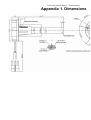
1
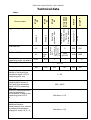
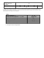
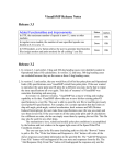
Fuel level sensors Fue eve sensors Stre a - Users manual Strela User manual 12.01.2012 Sapsan Control Co Ltd www.skontrol.ru Russia, Chelyabinsk 2012 Fuel level sensors Strela - User manual Content Description of fuel level sensors Strela ...............................................................................3 Technical data .................................................................................................................4 Short description of sensor product line .............................................................................6 Marking ….. .....................................................................................................................8 Delivery set .....................................................................................................................9 Installation of fuel level sensor...........................................................................................9 Installation steps.............................................................................................................10 Calibration of a tank ........................................................................................................13 Sensor Strela performance test .........................................................................................14 Service and application note .............................................................................................17 Transportation and storage .............................................................................................18 Manufacturer’s warranty ..................................................................................................18 Appendix 1. Dimensions ...................................................................................................19 Fuel level sensors Strela - User manual Description of fuel level sensors Fuel level sensors STRELA are used for petroleum, oil and lubricants. They enjoy wide application in automotive telematic systems for fuel level measurement and recording such as Intellitrac, GoSafe, Enfora, Teltonika. Various interfaces provide a suitable solution for all telematic systems. Fuel level sensor (FLS for short) Strela is a capacitive fuel level sensor without movable parts. Two aluminum tubes create a capacitor plate; its capacity depends on level inside tubes. FLS Strela is not intended for water measuring: with water inside tubes the output signal coincides with that of a full tank. There are different kinds of output signal. You can choose among: - Analog output (0.5-4.5 V, 0.5-3V,0.5-10V,0.5-12V) – Strela A - Frequency output (500-1500 Hz) – Strela F - Digital output (serial interface RS232 of 485 with 1024 or 4096 points resolution) – Strela D232, Strela D485 - Custom interfaces by demand: current 4-20 mA, MODBUS, CAN Electronic components of a sensor are immersed into elastic compound that provides maximum protection (IP66) and safety under any operation conditions. Measuring tubes are made of the material that doesn’t react with fuel components. Sensors are adjustable for desired tank height – you may cut them according to your tank height. The sensors should be recalibrated after cutting. If you cut less than 50% of initial length of the fuel level sensors Strela A and Strela F you mustn’t recalibrate the sensor but we would recommend doing that. The available lengths of sensors are the following: 350, 400, 500, 600, 700, 1000, 1400 and 2000 mm. It’s possible to produce sensors with any length that is so called composite sensors – sensors that consist of 2 or more parts. Sensors have built-in supply voltage stabilizer and sensor output doesn’t depend on onboard voltage. Sensors have built-in algorithm of data filtration and averaging that allows us to receive smooth fuel data. You can change averaging settings in Strela D232 and Strela D485 sensors. Data averaging in Strela A and Strela F must be defined while making an order before production. Sensors have self-diagnostic capabilities. There are sensor series electrically not connected to ground. Such sensors with carbon fiber body are marked PMY and can be powered directly from battery. Fuel level sensors Strela - User manual Technical data Upto 10* Min unit of measuring scale, not above DC supply voltage, V Maximum current, mA Range of low measurement values of fuel level from immersion depth of FLS measuring part, mm Range of upper measurement values of fuel level from immersion depth of FLS measuring part, mm Limits of permissible basic reduced measuring uncertainties of level to the measuring part of FLS, % Limits of permissible additional relative measurement error caused by ambient temperature change for every 10 ºС, % 0,01 0,01 Strela PP Strela D232 Strela D485 Strela F Pulses 4,5 Fuel level 100% frequency, Hz 2,5 Resistance equivalent, Ohm Analog, V 0,5 Fuel level 0% According to GOST 37.003.002-85, Range 800 Ohm 350Ohm,90 Ohm Analog, V Type of output signal Serial interface RS232 (RS 485) Protocols: Omnicom, Modbus Strela А3 Strela А1 Sensor model Strela А0 Table 1 0 500 500 4095 (65535) 1500 1500 1 1 1 10 12 ÷ 24 100 100 100 95 1 ÷ 20 200 ÷ 4000 Not above 0,5 Not above 0,5 100 100 Setting time of working mode, sec, not above Self-diagnostic feature Allowed cutting value, % 15 yes yes no 99 yes ye s yes - * Voltage can sometimes drop below 10V on 12V vehicle electrical systems. In this case sensor will not be able to form a signal of a full tank – signal will be limited by onboard voltage. We recommend using sensors with 0.5-7V output for 12V vehicles. Table 2 Working temperature, °С Average time before malfunction Тav*, hours y-percentile storageability time at = 95 %, years Protection class Power consumption, W Dimensions, mm Mass, kg -40 +65 Not less than 12 12500hours IP66 < 0.2 **70 х (24 + L) 0.3...3 Operation time Not limited * Failure criteria are functional failure or mismatch to declared measurement error. * L – the length of sensor sensing element. Fuel level sensors Strela - User manual Short description of sensor product range Strela А0 is a widely used fuel level sensor with analog voltage output. They can be connected to most of monitoring terminals with analog input up to 5 V (Lokarus, SKAUT, Autograph etc). Strela А1 is connected to terminals with analog input up to 24-30 V (Autograph, Teltonika, many other AVL terminals). Note: The voltage drop below 10 V is possible on the vehicles with 12 V electrical systems. In that case the sensor is not able to produce signal of full tank level. The signal will be limited by supply voltage. We recommend to order sensors with maximal output signal up to 7V for vehicle with 12 V electrical system. Strela A3 should be used in combination with standard fuel level indicators. Sensor Strela A3 can: Determinate fuel level and produce signal equal to the fuel amount in the tank. Produce signal of minimal fuel rest. The sensor may be used in combination with standard fuel level indicators. Equivalent of sensor resistance corresponds to the range 800 Ohm, 350 Ohm, 90 Ohm. As a part of GPS-monitoring system sensor has one fail - the voltage of analog input depends not only on sensor output, but also on standard indicator resistance and vehicle electrical system voltage. The accuracy of this sensor type is in-between standard sensor (minimal accuracy) and FLS Strela A1 or Strela A0. Strela F The fuel level sensors Strela F have greater accuracy and indication stability in comparison with Strela A. The tank fuel level is coded by frequency that linearly varies by changing of fuel level. The signal format is meander 50%; pulse height is equal to half of supply voltage. Currently such terminals as for example GOSAFE support these sensors. Main advantages: High resistance to external pickups, poor ground and other interfering signals due to great pulse height; No loss of data quality on terminal in compartment with analog output. Fuel level sensors Strela - User manual Strela PP The fuel level sensors Strela PP have greater accuracy and indication stability in comparison with Strela A. The output signal extends with pulse packet. Packet communication frequency is 1 minute for working mode and 15 seconds for test mode. Pulse count in working mode codes measurable value (from 500 to 1500 pulses). Pulse count in test mode codes error type. Pulse count in packet is over 380 Hz. The signal format is meander 50%; pulse height is equal to the half of supply voltage. Fig. 1. Format of output signal of FLS Strela PP Strela D232 (D485) FLS Strela D 232 (D485) with digital interface RS232 (RS48) is used with recording or monitoring systems that have the same input interface. Some compatible AVL devices are Intellitrac, Teltonika, DaisyTrack. Digital interface can work with MODBUS protocols or with Omnicom–compatible protocol. Protocol parameters: 19200 bit per second, 8 bit, 1 stop bit. Resolution is arbitrary, up to 63535 points per length. Main advantages: - High resistance to external pickups, poor ground and other interfering signals due to great pulse height; - No loss of data quality on terminal compared with analog output. Frequency and digital sensors have almost similar protection against interference. Fuel level sensors Strela - User manual Marking There are the following signs and notes on the sensor: - Trademark of the manufacturer; - Full name of the sensor; - Serial number; - Manufacturing date; - State register mark according to GOST 8.383. The front face of the explosion-protected sensors body is additionally marked with explosion protection 0ExiaIIBT6X and the range of ambient temperatures according to GOST P 51330.10-99 is specified. Marking method is labeling (by means of double-sided sealing tape) of a sign plate executed on a film by a silk-screening method, providing marking safety during all term of operation. Sensors are marked the following: Stela X-L (Z) (P), where X – sensor type (type of output signal: A, F, PP, D232, D 485 etc.); L- length of measuring part, mm; Z – firmware version, optional parameter; P – version marker without electric coupling of sensor body (with galvanic isolation), optional parameter. Example: Strela D232-500 PMY – sensor with RS 232 interface, initial length 500 mm, carbon plastic body with isolated ground. Fuel level sensors Strela - User manual Delivery set In the set there are sensor, 4-m cable, gasket, screws and passport. Fig. 2 Delivery set Installation of fuel level sensor It is recommended to install FLS Strela in the center of a tank, in addition to vehicle level sensor. In some cases (when vehicles are used on rugged terrain and tank shape is symmetric) the installation of TWO FLS is recommended. In this case you need to place them diagonally by opposite side walls of a tank. FLS Strela can be installed instead of truck level sensor with the same flange (SAE 5-pin, standard fastening for float fuel level sensors in CIS countries.) But in this case you should take into account that: 1. For better measurement the best place for FLS installation is geometric center of the tank (see Fig. 3). Truck level sensor is usually mounted not in the center. 2. FLS Strela has no output for vehicle fuel indicator, you will need FLS gauge unit to connect it to gauge. Fuel level sensors Strela - User manual Fig. 3. Recommended installation scheme Installation steps: 1) Drill holes for FLS flange (see fig. 4). Usually bi-metall drill head with 35mm diameter is used. Fig. 4. Bi-metall bore HAWERA Before drilling a hole in a tank with diesel fuel you should refuel it until full. In this case explosive vapor will not be produced. If you drill a hole in tank with petroleum you should load it with water instead of petroleum or demount the tank and evaporate the fuel rests! 2) Cut a FLS to desired length with a hacksaw – see fig. 5. You should leave about 10-20 mm for water on a bottom of the tank. Remove carefully the aluminum rasping between tubes. Fuel level sensors Strela - User manual Fig. 5 Sensor cutting 3) Calibrate a sensor (see section sensor calibration). Drill a central hole for sensor installation according to fig. 3. It is better to start from central hole, after that insert sensor in a hole and mark places for 5 screws. The screws are placed asymmetrically! We use standard size SAE-5 PIN – see dimensions in Appendix 1). 4) Place a gasket under the sensor (it is recommended to spread some silicone sealant on the gasket). Fix a sensor with screws (or with bolts in case of standard mount structure). According to wiring diagram in the passport connect minus side to ground, plus side to power (6-30V), FLS output to monitoring system input. Be aware of incorrect connection – FLS may be burned out! Please follow sensor connection circuit into vehicle electrical system! Don’t mix up cables. Wrong connection may bring sensor out of operation. Don’t apply supply voltage over +30V! Fig. 6 Strela A, Strela F, Strela PP connector and wiring Fig. 7 Strela D232. Strela D485 connector and wiring Table. 1 Strela D232 1 2 3 4 “-” “+” Rx Tx Strela D485 “-” “+” RS-A RS-B Colour brown blue Yellow-green Black Fuel level sensors Strela - User manual Calibration of a tank Liters 20 70 130 180 230 280 330 380 440 Sensor output value, Hz 300 370 460 530 600 665 730 795 870 The following table is an example of tank calibration table. The tank calibration consists in recording in the ROM of terminal or AVL software the conversion table of sensor output signal (voltage, frequency, pulses and others) to fuel volume value. Tank calibration: 1) Stop vehicle on the flat part of the road (road angularity must be minimized). 2) Discharge tank completely. 3) Add fuel till sensor will begin to change indication. Write added fuel value into t h e table. 4) Add fuel into tank by 10-50 liters (lowest value by min and max tank volume, greater value by half empty tank). Get new proper values of sensor output signal and write them down into the table. Fuel level sensors Strela - User manual Sensor Strela performance test Resistance between pipes works out about 500 kOhm. If value is a sequence less you should check whether there is a contamination between pipes. Strela A0. Without fuel immersion working sensor voltage at the output in reference to ground must range from 0.1 to 1.2 V (depending on cutting). Full tank output voltage may be 3.4÷4.5 V (depending on cutting). Strela A1. Without fuel immersion working sensor voltage at the output in reference to ground must range from 0.1 to 2.5 V (depending on cutting). Full tank output voltage may be 8 - 10 V (depending on cutting). When sensor touches water diagnostic code is 1.4 V. It is possible to produce versions with decreased output voltage (under order). Strela F. Without fuel immersion working sensor frequency at the output in reference to ground must range from 600 to 798 Hz (depending on cutting). Full tank frequency may be equal to 1300 – 1600 Hz (depending on cutting). When sensor touches water the diagnostic code is 340 Hz. Averaging time of frequency cuttable short sensors is 24 seconds, 16 seconds for frequency cuttable sensors. Strela PP. Without fuel immersion working sensor pulse packet at the output in reference to ground must be 600 – 750 pulses (depending on cutting). Full tank pulse packet must be equal to 1300÷1600 pulses (depending on cutting). When sensor touches wat er t h e d iag nost ic c o d e i s 3 4 0 p u lses p ack et . Packet commu n icat ion frequency is one minute for work mode and 15 seconds for test mode (see fig.1). Diagnostic error codes coincide with the codes of Strela F (Tab.6). Strela D232 and D485. The error codes are transferred with standard protocol (see Tab.6) The values of output signal of sensor not immersed into fuel are listed in the table 7. See error diagnostic codes in table 8. If you experience any problems with fuel level sensor work you need to fill in the reclamation on the website www.skontrol.ru/en/ and send it to the manufacturer. 7. Fuel level sensors Strela - User manual Table 6. Errors diagnostic code № 1 A Uout, V 1,0 F Fout, Hz 300 2 1,2 320 -2 3 1,4 340 -3 4 1,6 360 -4 5 6 1,8 2,0 380 400 -5 -6 7 2,2 420 -7 8 2,4 440 - 232 (485) Error description -1 Error code Sensor is not calibrated at lowest and upper point Sensor is not calibrated at upper point Oscillator frequency is equal to 0 Divided by zero, sensor is calibrated at one and the same point Reading error EEPROM Breakthrough upper range F> (Fmax+10%) ERROR_NO_CALIBRATION ERROR_NO_UP_CALIBRATION ERROR_NO_GENERATOR ERROR_ZERO_DIVIDE ERROR_EEPROM ERROR_FREQUENCY_ABOVE Breakthrough lowest range ERROR_FREQUENCY_BELOW F < (Fmin – 10%) Calibrating contact point is ERROR_CALIBRATION_SHORT_ CIRCUIT short-out Table 7. Values of output signal of sensor, not immersed into fuel CUTTABLE SENSORS Level of output signal of sensor not immersed into fuel (Output control) Sensor type Range Max Min Value at zero, uncut Averaging time, sec Unit Frequency cuttable 30% 500 1500 702,7 Hz 1 6 Frequency cuttalbe short 50% Analog cuttable 500 1500 797,6 Hz 2 4 0,5 4,5 1,31 V Analog cuttable 0-7 V 0 7 1,42 V 1 6 1 6 Analog cuttable 1-7 V 1 7 2,22 V 1 6 Analog cuttable 0-10 V 0 10 2,03 V 1 6 Fuel level sensors Strela - User manual Table.8 Description of diagnostic codes of sensor errors Error Oscillator frequency equal to 0 Working ability Description: oscillator is stopped Works – sensor doesn’t measure fuel level Type of failure: error is of sporadic* (water short-out when vehicle is in motion) or permanent (when mechanical short-circuit occur) nature. After cause is eliminated the sensor passes into work mode. Cause: Sensing element pipes are short-out – water in the fuel, mechanical short-circuit. Failure description Reading error Description: set sensor EEPROM calibration parameters failed. Type: error appears at once when you switch sensor on and has permanent nature, i.e. fuel immersion, wire short-circuits doesn’t effect on sensor output signal. Cause: possible static electricity impact by static electricity due to sensor cutting. Breakthrough at upper range F> (Fmax+10%) Description: sensor stands by zero if fuel level is low than gives an error. Type: error occurs on dry sensor. If you submerse sensor into fuel it works properly after it passes dead zone. Cause: more than 10% of noncuttable sensors or more than 40% of cuttable sensor was cut. The problem may also be caused by damage of sensing element. coating. Repair 1. Dry sensor, drain water from the tank; 2. Eliminate mechanical shortcircuit. Check resistance between sensing element pipes when sensor is off by circuit analyzer. Resistance value must range from 460 to 500 k Ohm. doesn’t work Replacement Check: close sensing element electrodes by metallic object, if sensor output signal doesn’t change then sensor is out of work. Dead zone below Replacement Check: Submerse sensor into fuel, it works properly after it passes dead zone. Fuel level sensors Strela - User manual Breakthrough lowest range F < (Fmin – 10%) Description: fuel level is over real value, sensor gives error from time to time. Type: error occurs at sensor immersion on the level close to maximal one or on any other level by water short-out. If error changes to error «Oscillator frequency equal to 0», then the problem is caused by water in the fuel. Cause: measurement fluid is different from diesel fuel or petroleum. Circuit shot of measuring element by water in tank. Works Check: by submersion of sensor into the fuel the output signal is proportional to sinkage. *Sporadic – from time to time. Service and application note Sensor operation requirements are stated in sensors certificate. To avoid sensor breakdown do not expose sensors to aggressive environments, electromagnetic fields as well as mechanical and weather loads, that exceed determined parameters in the present guide; Do not connect sensor to devices which have interface that fails to meet the specification, indicated in present performance specification and detailed engineering drawings; After sensor installation on vehicle or equipment it is recommended to seal all electrical connections; Sensors repair must be done by qualified staff that has repair certificate An exterior check is essential before introduction sensors into service. If there are mechanical damages (cracks, shears, dents etc) on the sensor than sensors introduction into service is not allowed; Sensors service must be done by staff that studied the device, its mode of functioning and all instruction indicated in sensor certificate; It is recommended to use proper grade diesel fuel that matches the range of temperature (summer, winter, arctic) according to GOST 305. Maintenance support Product does not need maintenance support. Maintenance repair Product is repairable. The manufacturer provides repair kits. Fuel level sensors Strela - User manual Transportation and storage Transportation The sensors transportation must be done in enclosed transport of any type that can provide protection for sensor against mechanic damage and exclude impact of atmospheric fallout onto package. During air transport sensors are places in heated pressurized modules. The air in vehicles should not contain acid, alkaline and others aggressive addictive agents. Transport package with packed sensor must be sealed. Sealing method should exclude access to packed sensor without removal of the seal. Storage Sensors have to be stored in closed or other rooms with natural ventilation, without artificially adjustable climatic conditions, not heated rooms. It is recommended to store sensors in the original package. Storage conditions of sensors in original package correspond to category C according to GOST 15150. Storage of sensors in the same facility with metal corrosive materials or materials containing aggressive addictive agents is not allowed. Storage of unpacked sensors isn't allowed. Manufacturer’s warranty 1. Guarantee period is 18 month from manufacture date. The manufacture date is indicated in product certificate. 2. Manufacturer guarantees product working ability under keeping of service rules, transportation and storage rules by customer. 3. Sensors with damage (cracks and shears, dents, impact marks, chamber choking etc) that occurred through customer’s fault due to violation of service, storing and transportation terms are not covered under warranty. Group of companies «SAPSAN» Rossiyskaya str., 194, Chelyaninsk, 454091 Russia [email protected] www.skontrol.ru Fuel level sensors Strela - Users manual Appendix 1. Dimensions