1
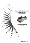
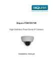
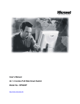
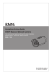
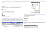
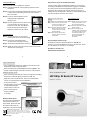
Ceiling/Wall Mounting
Step 2: Before Login to the Bullet IP Camera
Follow the steps below to install the IP Camera:
A client program will be automatically installed on your PC when
connecting to the Bullet IP Camera. Before logging in to the Bullet
IP Camera, please ensure downloading the ActiveX control is
allowed by either changing the ActiveX controls and plug-ins or
setting Internet's security level to default. For further details, please
refer to the Bullet IP Camera's user manual.
Step 1: Unpack the Bullet IP Camera package and take out the
Step 1: IP Camera.
Step 2: Connect the power/Ethernet/alarm/audio wires from ceiling
Step 1: or wall to the corresponding connectors of the camera's
Step 1: All-in-one Cable.
Step 3: Fix the IP Camera's Bracket on the
Step 3: ceiling/wall with supplied self
Step 3: tapping screws
Step 4: Use the supplied Inner Hex Wrench and
Step 3: cross screwdriver to loosen the hex
Step 3: bolt/screw on the side of the Bracket
Step 3: Mount and the Camera Housing to
Step 3: adjust the position of the IP Camera.
Lens Adjustment
Step 1: Unscrew the screw on the Camera
Step 1: Housing and remove the Front Housing.
Step 2: Connect the power/Audio/alarm,
Step 1: I/O wires to the matching connectors.
Step 3: Access the Camera Browser-viewer for viewing images.
Step 4: Adjust the Zoom/ Focus Ring Screw on the lens to set the
Step 1: desired zoom/ focal length.
ActiveX Controls and Plug-ins
Settings
Step 1: Start the Internet Explorer (IE).
Step 2: Select <Tools> from the main
Step 2: menu of the browser. Then
Step 2: Click <Internet Options>.
Step 3: Click the <Security> tab and
Step 2: select "Internet", and click
Step 2: <Custom level> to change
Step 2: ActiveX settings.
Step 4: Set "ActiveX controls and
Step 2: plug-ins" items to <Prompt>
Step 2: or <Enable>.
Internet Security Level
Step1: Start the IE.
Step 2: Select <Tools> from the main
Step 2: menu of the browser. Then
Step 2: Click <Internet Options>.
Step 3: Click the <Security> tab and
Step 2: select "Internet."
Step 4: Down the page, press
Step 2: "Default Level" and click "OK"
Step 2: to confirm the setting. Close
Step 2: the browser window, and
Step 2: open a new one later for
Step 2: accessing the Bullet
Step 2: IP Camera
Step 3: Bullet IP Camera Login
The Bullet IP Camera's default IP address is: 192.168.1.2.
Therefore, to access the Bullet IP Camera for the first time, set the
PC's IP address as: 192.168.1.X; for example:
IP Address: 192.168.1.100
Subnet Mask: 255.255.255.0
6
5
Communicate via
Login ID & Password
Key in the Bullet IP Camera's IP address in the URL bar of the
Web browser window and press "Enter."
Enter the default user name (root) and password (pass) in the
prompt request dialogue. Note that user name is case sensitive.
Install the ActiveX control
Quick Installation Guide
After connecting to the Bullet IP Camera, the request for installing
the ActiveX control will appear just below the URL bar.
HD1080p IR Bullet IP Camera
Right Click on the information bar, and press "Install ActiveX
Control..."to permit ActiveX control installation.
Model No.: SP5591A
In the pop-up security
warning window, click "Install"
to start downloading DC
Viewer software on the PC.
Press "Finish" after DC
Viewer installation
is complete.
Browser-based Viewer
The main page of the Bullet IP
Camera user interface is as
shown below. Please note that
the function buttons will vary
depending on the camera model.
WEEE Directive & Product Disposal
At the end its serviceable life ,this product should not be treated as
household or general waste. It should be handed over to the applicable
collection point for the recycling of electrical and electronic equipment, or
returned to the supplier for disposal.
P/N 2300-0694
7
Version 1.0
w w w . m i c r o n e t . c o m . t w
Indroduction
Package Contents
Micronet SP5591A HD1080p Bullet IP Camera is capable of serving
real-time streaming and makes image quality more smoothly. In
addition to MJPEG real time streaming, this camera develops H.264
codec to apply for high resolution digital broadcast.
Please check the package contains the following items listed below.
With sophisticated mechanical design plus cable management, the
HD1080p Bullet IP Camera is easy installed and aesthetic.
Bullet IP Camera M4 Self Tapping Plastic Screw
Anchors 5
(Cable included) Screws 5
1
Features
Power Terminal
Block
Progressive Scan CMOS Sensor
Desiccant
1
M4 Inner CD (bundled software Quick Guide
Hex Wrench and documentation)
Dual Streams, HD1080p + 720p real-time
H.264 and MJPEG compression
System Requirements
Motion Detection
To perform the IP Camera via web browser, please ensure your PC
is in good network connection, and meet system requirements as
described below.
Privacy Masks
WDR
Smart Picture Quality/3DNR
Items
System Requirement
Tampering Alarm
Personal
Intel®Pentium® M, 2.16 GHz or Intel ® CoreTM2 Duo, 2.0 GHz
Day/Night (ICR)
Computer 2 GB RAM or above
Operating
Micro SD Support
System
IR LED
Weatherproof (IP66 International)
Sunshield
ONVIF Support
Windows XP / VISTA / 7
Web
Microsoft Internet Explorer 6.0 or above
Browser
Firefox, Chrome, Safari
Network
10Base-T (10 Mbps) or 100Base-TX (100 Mbps) operation
Card
or above
Viewer
ActiveX control plug-in for Microsoft IE
1
2
Step 1: Bullet IP Camera Installation
Camera Connectors
Please follow the instructions below to complete Bullet IP Camera
installation.
2
Power up the Camera
5
Green
3
To power up the Bullet IP Camera, please plug the DC 12V cable
into the Camera's power terminal block. Alternatively, connect the
Ethernet cable to the camera's PoE port and plug the other end of
the cable into a PoE switch.
NOTE: NOTE: If using PoE, make sure Power Sourcing Equipment
NOTE: (PSE) is in use in the network.
Pink
1
Ethernet Cable Connection
4
Cable
Pin No. Definition
1 Alarm
1
ALM_IN
2
ALM_IN
2 Network
Remarks
Connect one end of the CAT5 Ethernet cable to the RJ-45
connector of the Bullet IP Camera, and the other end of the cable to
the network switch or PC.
Alarm connection
NOTE: NOTE: In some cases, you may need to use an Ethernet
NOTE: crossover cable when connecting the Bullet IP Camera
NOTE: directly to the PC.
3
ALM_OUT
4
ALM_OUT
_
RJ-45 connector with LED
Pink
Line In/ Mic In
Green
Line Out
1
DC 12V-1
DC (-)
2
GND
Reserved Power connection
3
DC 12V-2
DC (+)
_
Analog Video Output
(with PoE)
3 Audio I/O
4 Power
5 BNC
3
Two-way audio
transmission
NOTE: NOTE: Check the status of the link indicator and activity
NOTE: indicator LEDs; if the LEDs are unlit, please check
NOTE: LAN connection.
NOTE: Green Link Light indicates good network connection.
NOTE: Orange Activity Light flashes for network activity indication.
4