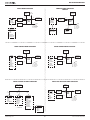
1
OCi OPERATING MANUAL OCi DIVE COMPUTER OPERATING MANUAL © 2002 Design, 2013 1 Doc. No. 12-5335-r02 (9/12/13) OCi OPERATING MANUAL Welcome to OCEANIC and Thank You for choosing the OCi © 2002 Design, 2013 2 Doc. No. 12-5335-r02 (9/12/13) OCi OPERATING MANUAL CONTENTS NOTICES............................................................................................... 4 Select OP (Operating) Mode ..................................................... 26 Scuba History - NORM, GAUG ................................................. 27 OCI ID (SERIAL NUMBER) ............................................................ 27 CLEAR - NORM .............................................................................. 27 FEATURES AND FUNCTIONS ............................................................. 5 DISPLAY LAYOUT ............................................................................ 6 ABBREVIATIONS ............................................................................. 6 INITIAL ACTIVATION........................................................................ 6 DIVE MODE FEATURES .................................................................... 28 NORM DIVE MODE STRUCTURE ................................................. 29 TRANSMITTER SIGNAL RECEPTION GUIDE .............................. 29 PROXIMITY OF TRANSMITTERS TO OCI .................................... 29 LINK INTERUPTION UNDERWATER ............................................ 29 WET ACTIVATION .......................................................................... 30 BACKLIGHT ................................................................................... 30 Autoglo ....................................................................................... 30 BAR GRAPHS ................................................................................ 30 TLBG........................................................................................... 30 VARI ............................................................................................ 30 DUAL ALGORITHM ........................................................................ 31 CONSERVATIVE FACTOR ............................................................. 31 DEEP STOP .................................................................................... 31 SAFETY STOP................................................................................ 31 OVERVIEW ....................................................................................... 7 MENU SYSTEM ................................................................................ 7 OPERATING MODE STRUCTURES ................................................ 8 PC INTERFACE ................................................................................ 9 AUDIBLE ALARM............................................................................. 9 BACKLIGHT ................................................................................... 10 Auto Glo ..................................................................................... 10 POWER SUPPLY, LOW BATTERY ................................................ 10 WATCH MODE .................................................................................... 11 WATCH DEFAULT TIME................................................................. 12 WATCH ALT 1 & 2 .......................................................................... 12 WATCH MAIN MENU ...................................................................... 12 Countdown Timer Setup ........................................................... 13 Chronograph .............................................................................. 13 Daily Alarm ................................................................................. 14 Set Time Menu ........................................................................... 14 Set Date Format ..................................................................... 14 Set Hour Format .................................................................... 14 Set Time of Day ..................................................................... 14 Set Date .................................................................................. 15 Set ALT (Alternate) Time ....................................................... 15 Set Default Time .................................................................... 15 Show Dual Time ..................................................................... 15 DIVE TIME REMAINING (DTR) ...................................................... 32 No Deco DTR (NDC) .................................................................. 32 O2 DTR (OTR) ............................................................................ 32 Air Time Remaining (ATR) ........................................................ 32 RESET DURING DIVE - ERROR .................................................... 32 NORM DIVE MODES .......................................................................... 33 NO DECO MAIN, ALTS................................................................... 34 DEEP STOP PREVIEW .................................................................. 34 DEEP STOP .................................................................................... 34 SAFETY STOP................................................................................ 35 NORM SURFACE MODES ................................................................. 16 Dive Computer Operating Modes ............................................ 17 Post Dive ................................................................................ 17 NORM SURFACE FUNCTIONS ..................................................... 17 NORM SURF MAIN AND ALTS ...................................................... 18 NORM MAIN MENU ........................................................................ 18 Fly/Desat .................................................................................... 19 Plan ............................................................................................. 19 Scuba Log - NORM, GAUG ....................................................... 20 DECOMPRESSION ........................................................................ 36 CONDITIONAL VIOLATION (CV) ................................................... 36 DELAYED VIOLATION 1 (DV1) ...................................................... 36 DELAYED VIOLATION 2 (DV2) ...................................................... 37 DELAYED VIOLATION 3 (DV3) ...................................................... 37 VIOLATION GAUGE MODE (VGM)................................................ 38 HIGH PO2 ....................................................................................... 38 HIGH O2 .......................................................................................... 39 Set Gas Menu - NORM .............................................................. 21 Set Gas 1 FO2/PO2 Alarm ..................................................... 20 Set Gas 2 (3, 4) FO2/PO2 Alarm ........................................... 21 Set FO2 Default...................................................................... 22 NORM GAS/TMT SWITCHING ........................................................... 40 DIGITAL GAUGE OP MODE .............................................................. 42 DIGITAL GAUG MODE STRUCTURE............................................ 43 GAUG SURFACE MAIN, ALTS ...................................................... 44 GAUG MAIN MENU ........................................................................ 44 Fly Time ...................................................................................... 44 Run Timer ................................................................................... 45 Set Alarms Menu - NORM, GAUG ............................................ 22 Set Audible Alarm .................................................................. 22 Set Depth Alarm..................................................................... 22 Set EDT Alarm........................................................................ 22 Set TLBG Alarm ..................................................................... 23 Set DTR Alarm ....................................................................... 23 Set Turn Pressure Alarm....................................................... 23 Set End Pressure Alarm........................................................ 23 GAUG DIVE MAIN, ALT.................................................................. 45 Delayed Violation 3 (DV3) ......................................................... 45 GAUG TMT SWITCHING ................................................................ 46 Set Utilities Menu - NORM, GAUG ........................................... 24 Set Water Type ....................................................................... 24 Set Wet Activation ................................................................. 24 Set Units ................................................................................. 24 Set Deep Stop ........................................................................ 24 Set Safety Stop ...................................................................... 25 Set Algorithm ......................................................................... 25 Set Conservative Factor ....................................................... 25 Set Backlight Duration .......................................................... 25 Set Sampling Rate ................................................................. 26 TMT Menu............................................................................... 26 Set TMT 1 (2, 3, 4) .................................................................. 26 © 2002 Design, 2013 3 Doc. No. 12-5335-r02 (9/12/13) OCi OPERATING MANUAL CONTENTS (continued) FREE & TECH FREE DIVE OP MODES ............................................ 47 OVERVIEW OF OPERATIONS....................................................... 48 SURFACE MAIN, ALTS .................................................................. 49 MAIN MENU .................................................................................... 49 Select Timer ............................................................................... 50 Countdown Timer Setup ........................................................... 50 Log & History Modes - Day, Full............................................... 50 Set Alarms Menu ....................................................................... 50 Set Audible Alarm .................................................................. 53 Set SRT (Surface Recovery Time) Alarm ............................ 54 Set RTI (Repeating Time Interval) Alarm ............................. 54 Set RDI (Repeating Depth Interval) Alarm ........................... 54 Set DD (Descending Depth) Alarms - FREE ........................ 55 Set DA (Descending Ascending Depth) Alarms - TECH .... 55 Set Utilities Menu ...................................................................... 56 Set Auto Glo - TECH .............................................................. 56 Set Sampling Rate - TECH .................................................... 57 Set DSD (Dive Start Depth) .................................................. 57 Set BDSI (Between Dive Surface Interval) ......................... 57 REFERENCE ...................................................................................... 66 PC INTERFACE .............................................................................. 67 PC Requirements ...................................................................... 67 CARE AND CLEANING .................................................................. 68 INSPECTIONS AND SERVICE ....................................................... 68 BATTERY REPLACEMENT............................................................ 68 Data Retention ........................................................................... 68 ALTITUDE SENSING AND ADJUSTMENT.................................... 69 TECHNICAL DATA ............................................................................. 70 Z+ ALGORITHM NDL CHART........................................................ 71 DSAT ALGORITHM NDL CHART .................................................. 71 SPECIFICATIONS........................................................................... 72 INSPECTION/SERVICE RECORD ..................................................... 74 OCEANIC WORLDWIDE .................................................................... 75 FREE & TECH FREE DIVE MAIN, ALTS ....................................... 58 FREE & TECH FREE DIVE ALARMS ............................................ 59 COMPASS MODE ............................................................................... 61 Compass Icons .......................................................................... 62 Compass Surface Mode Logic ................................................. 62 COMPASS MENU ........................................................................... 63 North OP Main............................................................................ 63 Reference OP Main .................................................................... 63 Reference Menu......................................................................... 64 Set Reference Heading ......................................................... 64 Reverse Reference Heading ................................................. 64 Calibration.................................................................................. 64 Declination ................................................................................. 65 COMPASS ALARMS ...................................................................... 65 NOTICES LIMITED TWO-YEAR WARRANTY For details, refer to the Product Warranty Registration Card provided. Register on line at www.oceanicworldwide.com COPYRIGHT NOTICE This operating manual is copyrighted, all rights are reserved. It may not, in whole or in part, be copied, photocopied, reproduced, translated, or reduced to any electronic medium or machine readable form without prior consent in writing from Oceanic/2002 Design. OCi Operating Manual, Doc. No. 12-5335 © 2002 Design, 2013 San Leandro, CA USA 94577 TRADEMARK, TRADE NAME, AND SERVICE MARK NOTICE Oceanic, the Oceanic logo type, OCi, the OCi logo, Air Time Remaining (ATR), Diver Replaceable Batteries, Graphic Diver Interface, Tissue Loading Bar Graph (TLBG), Pre Dive Planning Sequence (PDPS), Set Point, Control Console, Turn Gas Alarm, OceanLog, and Dual Algorithm are all registered and unregistered trademarks, trade names, and service marks of Oceanic. All rights are reserved. PATENT NOTICE U.S. Patents have been issued, or applied for, to protect the following design features: Dive Computer with Free Dive Mode and/or Wireless Data Transmission (U.S. Patent no. 7,797,124), Air Time Remaining (U.S. Patent no. 4,586,136 and 6,543,444) and Data Sensing and Processing Device (U.S. Patent no. 4,882,678). Other patents pending. User Setable Display (U.S. Patent no. 5,845,235) is owned by Suunto Oy (Finland DECOMPRESSION MODEL The programs within the OCi simulate the absorption of nitrogen into the body by using a mathematical model. This model is merely a way to apply a limited set of data to a large range of experiences. The OCi dive computer model is based upon the latest research and experiments in decompression theory. Still, using the OCi, just as using the U.S. Navy (or other) No Decompression Tables, is no guarantee of avoiding decompression sickness, i.e. “the bends.” Every diver’s physiology is different, and can even vary from day to day. No machine can predict how your body will react to a particular dive profile. © 2002 Design, 2013 4 Doc. No. 12-5335-r02 (9/12/13) OCi OPERATING MANUAL FEATURES AND FUNCTIONS © 2002 Design, 2013 5 Doc. No. 12-5335-r02 (9/12/13) OCi OPERATING MANUAL DISPLAY LAYOUT ICONS Depth id Time id Temp or Heading Dot Matrix Daily AL or TMT Link FO2 is Nitrox Pressure id Air Time Low Battery DISPLAY ABBREVIATIONS A = AM or Am (time) ACTIV = Activation AL = Alarm ALGO = Algorithm ATR = Air Time Remaining AUD = Audible BATT = Battery BDSI = Between Dive Surface Interval C = Centigrade (temperature) CAL = Calibrate (compass) CDT = Countdown Timer CHRONO = Chronograph (stop watch) COMM = Communications CONS = Conservative Factor CONSERV = Conservative Factor D.M = Day & Month (date) DA = Descend/Ascend (depth alarm) DD = Descending Depth (alarm) DECLIN = Declination (compass) DECO = Decompression DESAT = Desaturation (nitrogen) DFLT = Default DSAT = Algorithm type DSD = Dive Start Depth DTR = Dive Time Remaining DURA = Duration (backlight time) E = East (compass) EDT = Elapsed Dive Time EL = Elevation (altitude level) F = Farenheit (temperature) FO2 FORM FREE FRSH FT GAUG GLO H HIST HR ID INTVL IMP M M M.D MAX MET MIN N NDC NDL NE NI NO-D NORM NW Nx O2 OP = Fractional % of Oxygen = Format (date, time) = Free Dive Mode = Fresh (water) = Feet (depth) = Digital Gauge Dive Mode = Glow (backlight) = Hour (time) = History = Hour (time) = Identification (module) = Interval (time) = Imperial (units) = Meters (depth) = Minutes (time) = Month & Day (date) = Maximum = Metric (units) = Minutes (time) = North (compass) = No Deco Time Remaining = No Deco Limit (time) = Northeast (compass) = Nitrogen = No Decompression = Normal Dive Mode = Northwest (compass) = Nitrox (gas) = Oxygen = Operating (mode) OTR P PC PO2 PSI RDI REF REPET REV RTI S S SAT SE SEC SEL SN SPG SRT SURF SW TAT TECH TLBG TMR TMT UTIL VARI VIOL W Z+ = O2 Time Remaining = PM or Pm (time) = Personal Computer = Partial Pressure of O2 (ATA) = Pounds per Square Inch (pressure) = Repeating Depth Interval = Reference (compass mode) = Repeating (interval alarm) = Revision (firmware) = Repeating Time Interval = Seconds (time) = South (compass) = Saturation = Southeast (compass) = Seconds (time) = Select = Serial Number = Submersible Pressure Gauge = Surface Recovery Time = Surface (mode, time) = Southwest (compass) = Total Ascent Time (deco) = Technical Free Dive Mode = Tissue Loading Bar Graph = Timer = Transmitter (tank pressure) = Utilities (set mode) = Variable Ascent Rate Indicator = Violation = West (compass) = Algorithm type INITIAL ACTIVATION OCi Watch/Dive Computers are placed in a Deep Sleep mode prior to being shipped from the factory. The intent is to extend storage life of the Battery for up to 7 years, before the unit is initially placed in service. In this mode, Date and Time are updated as they normally would be. However, they are not displayed. Upon waking the OCi up, the correct Date and USA Pacific Time will be displayed and it will be ready to operate with full functions. To wake the OCi up from Deep Sleep mode, simultaneously depress the upper/right (S) and lower/left (A) buttons for 3 seconds until the display comes full ON displaying the Watch Main Time screen, then release them. NOTE: Once the OCi is brought out of the Deep Sleep mode, it can only be placed back into it by the factory. © 2002 Design, 2013 6 Doc. No. 12-5335-r02 (9/12/13) OCi OPERATING MANUAL OVERVIEW Watch, Pressure Integrated Dive Computer featuring >> • • • • • • • • • • • • • • 4 Control Buttons. 6 Operating Modes. Watch Default Time (Main or ALT). Watch Dual Time (Main or ALT). Audible Alarm with flashing LED. Digital Compass. Altitude Compensation. 15+ Menus. 60+ Set Selections. Increase/Decrease Set Values. up to 4 Nitrox Gas Mixes. up to 4 Pressure Transmitters. 30+ Warnings/Alarms. User Replaceable Battery. • • • • • • • • • • • • • • Dual Algorithm. NDL Conservative Factor. No Deco Deep Stop. No Deco Safety Stop. Gas Switching. Transmitter Switching. Gauge Dive Run Timer. Depths to 330 FT/100 M. Tech Free Depths to 495 FT/150 M. Free & Tech Free Dive Run Timers. Free & Tech Free Countdown Timers. Variable Ascent Rate. PC Settings Upload/Data Download. User Upgradeable Firmware. INTERACTIVE CONTROL CONSOLE The Interactive Control Console utilizes 4 control buttons that allow you to maneuver through the OCi's unique system of menus. M S The buttons will be referred to as M, S, L, and A. • • • • OCi Upper/Left - Mode (M) button. Upper/Right - Select (S) button. Lower/Right - Light (L) button. Lower/Left - Advance (A) button. L A MENU SYSTEM The Dot Matrix located in the middle of the LCD viewing area is used to display alpha numeric messages and measured values as well as Menu type systems for selection of settings and various auxiliary functions. It also serves as the Digital Compass which can be accessed during operation in any mode. There are 15 Menus that include the • Watch Main Menu. • NORM Main Menu. • GAUG Main Menu. • FREE Main Menu. • TECH FREE Main Menu. • Compass Main Menu. • Log/History Menu. • Gas/TMT Switch Menu. • • • • • • • FREE MAIN MENU Set Time Menu. Set Gas Menu. Set Alarms Menu. Set Utilities Menu. Set TMT Menu. Set Compass Declination Menu. Compass Reference Menu. SEL > SEL TIMER CDT SETUP LOG/HISTORY Each Menu has a Start (First) selection and a Stop (Last) selection. Upon entering a Menu, movement through it begins at the Start (First) selection, then continues in a rolling manner down the screen showing selections in groups of 3 items. • The sample at the right shows how a menu would look if all of the selections could be displayed on one screen. Menu button action >> M (< 2 sec) - to access Menu. A (< 2 sec) - to step down the screen (forward) through selections. M (< 2 sec) - to step up the screen (backward) through selections. S (< 2 sec) - to access selection indicated by Arrow icon ( > ). SET ALARMS SET UTILITIES OP MODE OCi ID Sample Menu (all selections shown) Right Arrow icon ( > ) at the left indicates the selection. Down Arrow icon ( v ) at the right indicates that additional selections are available below (after) those shown. Up Arrow icon ( ^ ) at the right indicates that additional selections are available above (before) those shown. M S There is a selection above. Selection can be accessed. There is a selection below. A © 2002 Design, 2013 L 7 Doc. No. 12-5335-r02 (9/12/13) OCi OPERATING MANUAL WATCH MODE STRUCTURE COMPASS MODE STRUCTURE SURFACE Dive Op Mode 2s Select CDT Setup Chrono Daily AL > Time Menu Main Menu Watch or DC Main Ack Daily AL 2s <2s <2s Compass Op Main 2s M 2s S Select North Reference Calibrate > Set Declin WATCH MAIN ALTs A <2s L Main Menu Set Declin Menu > Declin Off Declin East Declin West GAUG SURFACE MODE STRUCTURE Watch Mode 2s 2s 2s <2s 2s M S Compass Op Main Select > Fly Log Set A Set U OP Mode History OCi ID Batt/TMT SURF MAIN ALTs <2s Light -----------< 2 s - On/Off. 2 s - reset timer. On - during Aud. Off - by timer. (if REF) Ref Menu > Set Heading Reverse Watch Mode Main Menu S COMP OP MAIN A L <2s NORM SURFACE MODE STRUCTURE Select > Fly/Desat Plan Log Set G Set A Set U OP Mode History OCi ID Batt/TMT M 2s Light -----------< 2 s - On/Off. 2 s - reset timer. On - during Aud. Off - by timer. Set Time Menu > Date Format Hour Format Time Date ALT Time Default Time Show Dual <2s A L Light -----------< 2 s - On/Off. 2 s - reset timer. On - during Aud. Off - by timer. NORM & GAUG SET MENU STRUCTURE Main Menu 2s <2s M 2s S Compass Op Main SURF MAIN ALTs <2s L A Light -----------< 2 s - On/Off. 2 s - reset timer. On - during Aud. Off - by timer. FREE & TECH FREE SURF MODE STRUCTURE NORM, GAUG Main Menu Watch Main 2s S <2s Set G Menu** > Gas 1 Gas 2 Gas 3 Gas 4 FO2 Default S <2s Set A Menu > Aud AL Depth AL EDT AL TLBG AL** DTR AL** Turn AL End AL ** = NORM only © 2002 Design, 2013 Select > SEL Timer CDT Setup Log/History Set A Set U OP Mode OCi ID S <2s Set U Menu Water Type Wet Activ Units Deep Stop** Safety Stop** Algorithm** Conserv** Glo Dura Sampling > TMT Menu Main Menu 2s <2s 2s M S Compass Op Main SURF MAIN ALTs <2s A L Light -----------< 2 s - On/Off. 2 s - reset timer. On - during Aud. Off - by timer. Set TMT Menu > TMT 1 TMT 2 TMT 3 TMT 4 8 Doc. No. 12-5335-r02 (9/12/13) OCi OPERATING MANUAL PC (PERSONAL COMPUTER) INTERFACE Interface with a PC (including Apple), to allow uploading settings and downloading data, is accomplished by connecting the OCi to a PC USB port using the special Oceanic USB interface cable. The software program together with the USB driver required is on the Oceanic Product CD, or it can be downloaded from the Oceanic web site. The program's Help serves as the user manual which can be printed for personal use. The settings upload portion of the computer interface program can be used to set/change the Watch, Scuba, and Free mode selections using the same interface system. Information available for retrieval (download) from the OCi to the download portion of the program includes items such as dive number, surface interval time, start/end depths, max depth, elapsed dive time, start date/time, lowest temperature, sampling rate, dive profile (with Earmarks), and set points. The computer interface program also allows update of select versions of the OCi's firmware (operating system software). • Refer to page 67 for more details relating to the computer interface system. AUDIBLE ALARM While operating in NORM or GAUG Mode the Audible will emit 1 beep per second for 10 seconds when alarms strike, unless it is set Off. During that time, the Audible can be silenced by pressing the S button momentarily (less than 2 seconds). An LED Warning Light, on the side of the housing, is synchronized with the Audible and flashes as the Audible sounds. It will turn off when the Alarm is silenced. The Audible and LED will not be active if the Audible is Set OFF (a Set Alarms setting). FREE Dive Modes have their own Alarms which emit multiple beeps multiple times which cannot be acknowledged or set Off. Events that emit (10) beeps >> each sound for .500 sec with .500 sec silence between beeps: • Watch Daily Alarm. • Watch CDT Alarm. • NORM, GAUG - ATR Warning & Alarm. • NORM, GAUG - Turn Pressure Alarm (TMT 1). • NORM, GAUG - End Pressure Alarm (TMT in use). • NORM, GAUG - Loss of Link (Dive Mode). • NORM, GAUG - Ascent Rate too fast. • NORM, GAUG - Depth Alarm. • NORM, GAUG - EDT Alarm. • NORM - DTR Alarm. • NORM - TLBG Alarm. • NORM - entry into Deco. • NORM - Conditional Violation. • NORM - Delayed Violations 1, 2. • NORM, GAUG - Delayed Violation 3. • NORM, GAUG - entry into Violation Gauge Mode. • NORM - PO2 Warning and Alarm. • NORM - O2 Warning and Alarm. • NORM - Gas Switch Alarm. Events that emit (3) beeps >> each sound for .500 sec with .500 sec silence between beeps: • NORM, GAUG - Ascent Rate warning. • FREE - Delayed Violation 3. Events that emit (3) sets of (3) beeps >> each sound for .500 sec with .250 sec silence between beeps and .500 sec silence between sets: • FREE, TECH FREE - SRT Alarm. • FREE, TECH FREE - RDI Alarm. RDI does not alarm at the DD or DA alarm depths. • FREE, TECH FREE - CDT Alarm. • FREE - TLBG Alarm. • FREE - Violation, entry into Deco. Events that emit (3) sets of (3) beeps >> each sound for .125 sec with .125 sec silence between beeps and .250 sec silence between sets: • FREE - DD1 to DD3 Alarms. Events that emit (2) beeps >> each sound for 1 sec with .500 sec silence between beeps: • FREE, TECH FREE - RTI Alarm. Events that emit (1, 2 or 3)* sets of (1 to 10)* beeps >> each sound for .125 sec with .125 sec silence between beeps and .250 sec silence between sets: • TECH FREE - DA1 to DA6 Alarms. *Each DA is user adjustable. © 2002 Design, 2013 9 Doc. No. 12-5335-r02 (9/12/13) OCi OPERATING MANUAL BACKLIGHT To turn the Backlight On, press and release the L button (< 2 seconds). The Backlight will remain On for the duration time set (a Set Utilities selection) unless you turn it Off during that time by pressing S again. • The Backlight will come On (even if set OFF) when alarms strike and remain On until turned Off by pressing S, or it turns Off automatically after 10 seconds . • Pressing and releasing the L button (< 2 seconds), while the Backlight is On, will turn it Off. • Depressing the L button for 2 seconds, while the Backlight is On, will reset the duration timer and extend the On time to the full duration time set. • If the L button is depressed for more than 60 seconds, the Backlight will be disabled and not turn On until the button is released then pressed/released again. • The Backlight will be disabled when there is a Low Battery alarm condition, and be re enabled once the battery is replaced. • Extensive use of the Backlight reduces Battery use life. • Turning the Backlight Off when it is not being used will help extend Battery use life. • The Backlight does not operate when the unit is connected to a PC or Mac. Auto Glo (TECH FREE mode only): When Auto Glo (a TECH FREE mode Set Utilities selection) is set On, Backlight operation on the surface in TECH FREE mode is controlled as it normally would be by the L button and duration time set. However, upon entry into TECH FREE dive mode, the Backlight activates (turns On) automatically and remains On throughout the full dive until entry into Surface mode when the Backlight operation reverts to normal. POWER SUPPLY • Battery >> (1) 3 vdc, CR2450, Lithium battery. • Shelf life >> up to 7 years (when shipped from factory in Deep Sleep mode). • Use life >> 1 year or 300 dive hours if (2) 1 hour dives per dive day. • Replacement >> user replaceable (annual recommended). Battery icon: • Warning >> icon on solid when < 2.75 volts, battery change recommended. • Alarm >> icon on flashing with message when < 2.50 volts, change the battery. Low Battery when on the surface: <= 2.75 volts (warning level) • Backlight is completely disabled*. • Battery icon (shell with inner bar) appears solid (Fig. 1Aa). • If a dive is started, the icon is not displayed on the dive mode screens. • Watch and DC functions*, including Compass Mode, continue to be available. *TECH FREE dives cannot be started if Auto Glo is set On, due to the Backlight being disabled. <=2.50 volts (Too Low - alarm level) • All DC operations cease and the unit operates only as a Watch with Compass (view only). • Low Battery icon (shell only with no inner bar) flashes for 5 seconds and operation reverts to Watch Time with Compass allowed (view only) until the Battery is changed or voltage cannot sustain operation, then the graphic CHANGE BATTERY flashes until the Battery is changed or voltage drops to the level at which operation cannot be maintained. a Fig. 1A - LOW BATT WARNING (Watch Main Time) Low Battery during a dive: <= 2.75 volts (warning level) • Backlight is completely disabled**. • Full DC functions and Compass continue to be available. • Battery icon is not displayed on the dive mode screens. • Battery icon (shell with inner bar) appears solid upon entry into Surface Mode. <= 2.50 volts (Too Low - alarm level) • Backlight is completely disabled**. • Full DC functions continue to be available during the dive. • Battery icon is not displayed on the dive mode screens. • Upon entry into Surface Mode, the Battery icon (shell only with no inner bar) and graphic CHANGE BATTERY flash for 5 seconds (Fig. 1B) and operation reverts to Watch Time with Compass (view only) allowed, until the Battery is changed or voltage cannot sustain operation, then the graphic CHANGE BATTERY flashes until the Battery is changed or voltage drops to the level at which operation cannot be maintained. Fig. 1B - LOW BATT ALARM (NORM Surface Main) **The Backlight will not be disabled during TECH FREE dives, when Auto Glo is set On. Transmitter Low Battery Alarm, surface only: =< 2.75 volts (warning level) • The graphics TMTx BATT LOW appear solid on the Battery Status screen (refer to page 27). • Watch and DC functions, including Compass Mode, will not be affected. =< 2.50 volts (Too Low - alarm level) • The graphics TMTx BATT LOW flash on the Status screen. • The graphics TMTx BATT LOW also alternate with the NORM (or GAUG) graphics on the matrix portion of the NORM (or GAUG) Surface Main screen (Fig. 2). • TMT operation will continue until tank pressure decreases to 50 PSI (3 BAR), then it will disconnect (loose signal). © 2002 Design, 2013 10 Fig. 2 - TMT LOW BATT ALARM (Surface Main) Doc. No. 12-5335-r02 (9/12/13) OCi OPERATING MANUAL WATCH MODE © 2002 Design, 2013 11 Doc. No. 12-5335-r02 (9/12/13) OCi OPERATING MANUAL WATCH DEFAULT TIME Default Time is the Time that is displayed on the Watch until changed. It is also the Time viewed during operation in DC (Dive Computer) Modes. Main Time is the current Time at your home location and is normally selected as the Watch Default Time. Alternate Time will be the current time at a remote travel location. Upon arrival at the location, Alternate Time can be interchanged with Main Time to make it the Watch Default Time. When it is not selected to be the Default Time, it can be viewed on the Watch ALT 1 screen, or it can be displayed on the Watch screen with Main Time and will be labeled as Dual Time Once Alternate Time is set, by hour differential, it will automatically change when Time of Day is set/changed. When Alternate Time is selected to be the Watch Default Time (while at a travel location), it will change directly when Time of Day is changed and Main (home) Time will then change by a differential opposite the one set for Alternate Time. WATCH DEFAULT TIME, information includes (Fig. 3A/B/C): > Dual Time (hr:min) with icon, if Show Dual is set for YES. > Time of Day (hr:min_sec), Main (home) or Alternate (away), with A or P if 12 hour format, & graphic ALT if Alternate. > Day of Week graphic MON, TUE, WED, THU, FRI, SAT, or SUN. > Month.Day (or Day.Month). > TLBG, if any after NORM or FREE dives. > Alarm (speaker) icon, if the Daily Alarm is set On. > Battery icon, if a Low Battery condition. • • • • • • • Fig. 3B - DEFAULT TIME (Main selected, with Dual) M (< 2 sec) - to access the Watch Main Menu. M (2 sec) - to access the DC (Dive Computer) Mode last selected. A (< 2 sec) - to access the Watch ALT 1 screen. Bypassed to ALT 2 if Show Dual is set for YES. S (< 2 sec) - to silence the Daily Alarm. S (2 sec) - to access Compass Mode. L (< 2 sec) - to toggle the Backlight On/Off. Will be On for the duration time set. L (2 sec), while the Backlight is On, - to reset the timer to keep it On for the full duration time set. WATCH ALT 1, information includes (Fig. 4A): > Time of Day (hr:min_sec), Alternate (away) or Main (home), with A or P if 12 hour format, & graphic ALT if Alternate. > Day of Week graphic MON, TUE, WED, THU, FRI, SAT, or SUN. > Month.Day (or Day.Month). > TLBG, if any after NORM or FREE dives. > Alarm (speaker) icon, if the Daily Alarm is set On. > Battery icon, if a Low Battery condition. • • • • Fig. 3A - DEFAULT TIME (Main selected, no Dual) A (< 2 sec) - to access ALT 2. Reverts to the Default Time screen after 10 seconds if A is not pressed. L (< 2 sec) - to toggle the Backlight On/Off. Will be On for the duration time set. L (2 sec), while the Backlight is On, - to reset the timer to keep it On for the full duration time set. Fig. 3C - DEFAULT TIME (Alternate selected, no Dual) Fig. 4A - WATCH ALT 1 WATCH ALT 2, information includes (Fig. 4B): > Graphic CDT (Countdown Timer) with OFF or Countdown Time (hr:min), time previously set or that remaining. > Altitude graphic EL2 (to EL 7), blank if Sea level. > Temperature with ° icon and graphic F (or C). If the CDT is On and running with time remaining • S (< 2 sec) - to stop/start the Timer. • A (2 sec) - to reset the Timer to the hr:min value set. • A (< 2 sec) - to revert to the Watch Default Time screen with the CDT running in the background. Fig. 4B - WATCH ALT 2 If the CDT is Off, or it was running and has counted down to 0:00, operation reverts to the Watch Default Time screen after 10 seconds or by pressing A (< 2 sec). • L (< 2 sec) - to toggle the Backlight On/Off. Will be On for the duration time set. • L (2 sec), while the Backlight is On, - to reset the timer to keep it On for the full duration time set. WATCH MAIN MENU, information includes (Fig. 5A/B): > CDT Setup >> To select Off, On, or Set (hr:min). > Chrono >> To Start, Stop, Recall Laps, and Reset. > Daily Alarm >> To select Off, On, or Set (hr:min). > Time Menu >> To select/set Date Format, Hour Format, Time, Date, Alternate Time, Default Time, Show Dual. Fig. 5A - MAIN MENU (first 3 items) • M or S (2 sec) - to revert to the Watch Default Time screen. • If no button is pressed during a period of 2 minutes, operation will revert to the Watch Default Time screen. • A (< 2 sec) - to step forward (advance down) through the selections indicated by the pointer icon ( > ) along the left side of the matrix. Once the pointer icon ( > ) reaches the lower selection on the matrix, it will remain in that position pointing to the next selection that appears when A is pressed. A down arrow icon located on the right side of the matrix indicates that additional selections are available below those displayed. © 2002 Design, 2013 12 Fig. 5B - MAIN MENU (last 3 items) Doc. No. 12-5335-r02 (9/12/13) OCi OPERATING MANUAL • M (< 2 sec) will step back through the selections. Once the pointer icon ( > ) reaches the upper selection on the matrix, it will remain in that position pointing to the next selection that appears when M is pressed. An up arrow icon located on the right side of the matrix indicates that additional selections are available above those displayed. • S (< 2 sec) when the pointer ( > ) icon is next a selection will access (go to) that item. CDT (Countdown Timer) SETUP, information includes (Fig. 6A/B): > Graphics CDT SETUP solid with OFF (or ON) flashing and SET solid. > Remaining Countdown Time (hr:min) if ON and a countdown is in progress, or 0:00 if ON and no time is remaining, or 0:00 or the time previously set if OFF. • A (< 2 sec) - to step forward through the selections OFF, ON, and SET. • S (2 sec) - to revert to the Watch Main Menu. If OFF or ON is flashing, S (< 2 sec) will save the selection and revert to the Watch Main Menu. ON does not start the countdown, start/stop is controlled while viewing the Watch ALT 2 screen. Fig. 6A - CDT SETUP (Off, not yet set) If SET is flashing, S (< 2 sec) will access Set CDT. Once the CDT has been set and turned ON (ready to start, but not started), it will be displayed on the Watch ALT 2 screen where it can be started, stopped, or reset until set OFF. When the countdown reaches 0:00, the Audible will sound (10 sec) during which 0:00 and CDT will be displayed on the Watch Default Time screen while the audible sounds. Upon entering any Dive Computer mode, Watch CDT operation will be terminated and the countdown time will revert to the hr:min value previously set. Set > > > • • • • • • • • • Fig. 6B - CDT SETUP (On, running) CDT, information includes (Fig. 6C): Graphics CDT SETUP, solid. Graphics OFF, ON, and SET solid. Time (hr:min), Hour digits flashing. A (hold) - to scroll upward through the Hour set points at 8/second from 0: to 23: in 1 hour (1:) increments. A (< 2 sec) - to step up through the set points one at a time. M (< 2 sec) - to step back through the set points one at a time. S (< 2 sec) - to save the Hour setting and flash the Minute digits. A (hold) - to scroll upward through the Minutes set points at 8/second from :00 to :59 in 1 minute (:01) increments. A (< 2 sec) - to step up through the set points one at a time. M (< 2 sec) - to step back through the set points one at a time. S (< 2 sec) - to save the hour:minute set point, with SET flashing allowing OFF or ON to be selected (see Setup above). S (2 sec) - to revert to the Watch Main Menu. FREE Mode has a separate (min:sec) CDT. Fig. 6C - SET CDT (hour then minutes) CHRONOGRAPH (Stop Watch/Lap Timer), information includes (Fig. 7A/B): > Graphic LAP1 (or 2 up to 9) if previously started or blank if not yet started > Graphic CHRONO. > Elapsed time if previously started, or 0:00:00.00 (hr:min:sec_ .01 sec) if not yet started, flashing. • S (upon press) - to display the graphic LAP1 and start the Chrono (run time) which will begin counting up from 0:00:00.00 to 9:59:59.99 hr:min:sec_ .01sec in increments of .01 (1/100th sec). After the first 4.99 seconds, the .01 sec digits will be displayed as 2 dashes ( . - - ). • S (upon press) - to save Lap 1’s time and display the graphic LAP2 with the Timer continuing to count up. Total Run Time is always displayed until the Chrono is stopped. • S (upon press) - to freeze Lap Times (1 up to 9). After 9, subsequent Laps will be recorded and the earliest Lap discarded. Freezing of a Lap Time is prevented when S is operated during an Alarm strike. If the Chrono continues to run and reaches 9:59:59.99, it will stop and record that as a Lap. Subsequent presses of S then have no effect. Fig. 7A - CHRONO (started, running) • A (< 2 sec) - to stop the Chrono and recall Lap 1 displaying the graphic LAP1 and the Lap time. Subsequent presses of A will recall the other Laps. • A (2 sec) - to stop the Chrono if running, and reset it to 0:00:00.00. • M (2 sec) - to revert to Watch Main with Chrono running in the background. Once the Chrono has been set and started, it will remain on display (or continue to run in the background) while on the surface until reset by the user. Upon descending to 5 FT/1.5 M (i.e., entry into Dive Mode), operation will be terminated and the counter will reset to 0:00:00.00 (hr:min:sec.xx). © 2002 Design, 2013 13 Fig. 7B - CHRONO (started, frozen or recalled) Doc. No. 12-5335-r02 (9/12/13) OCi OPERATING MANUAL DAILY ALARM When set On, the Daily Alarm, that runs in the background, will sound the Audible at the time set every day when that time equals the Watch Default Time selected. The Audible will not sound while operating in dive computer modes. Daily Alarm Status, information includes (Fig. 8A): > Graphics DAILY ALARM solid, with OFF (or ON) flashing. > Alarm Time (hr:min) last set, with graphic AM (or PM) if 12 Hour Format. • A (< 2 sec) - to step forward (down) through the selections OFF, ON, and SET. • M (< 2 sec) - to step back (up) through the selections. • S (< 2 sec) - to save the selection that is flashing. Fig. 8A - DAILY ALARM STATUS (upon access) >> If OFF is selected, operation reverts to the Menu. >> If ON is selected, operation reverts to the Menu with the Alarm enabled. >> If SET is selected, Set Daily Alarm is accessed. Set Daily Alarm, information includes (Fig. 8B): > Graphics DAILY ALARM, OFF, ON, and SET solid. > Alarm Time (hr:min) with Hour digits flashing, with AM (or PM). • • • • • • • • A (hold) - to scroll upward through Hour set points 8/sec from 0: to 23: in increments of 1: (hr). A (< 2 sec) - to step upward through Hour set points one at a time. M (< 2 sec) - to step back through Hour set points one at a time. S (< 2 sec) - to save the Hour set point and flash the Minute digits. A (hold) - to scroll upward through Minute set points 8/sec from :00 to :59 in increments of :01 (min). A (< 2 sec) - to step upward through Minute set points one at a time. M (< 2 sec) - to step back through Minute set points one at a time. S (< 2 sec) - to save the setting (hr:min digits solid) and flash the graphic SET allowing ON or OFF to be selected/saved. Fig. 8B - SET DAILY AL SET TIME MENU, information includes (Fig. 9): > Graphic SEL (Select). > Graphic selections - DATE FORM, HOUR FORM, TIME, DATE, ALT TIME, DFLT TIME, SHOW DUAL (with 3 per screen). • A (< 2 sec) - to step down (forward) through the selections. • M (< 2 sec) - to step up (back) through the selections. • S (< 2 sec) - to access the menu selection indicated by the pointer icon ( > ). Set Date Format, information includes (Fig. 10): Date Format establishes the position that the Month (M) digits are displayed relative to the Day (D) digits, on the left or right. > Graphic DATE FORM (Format). > Graphics M.D and D.M with the pointer icon ( > ) next to the one previously saved flashing. Fig. 9 - SET TIME MENU • A or M (< 2 sec) - to toggle between M.D and D.M. • S (< 2 sec) - to save the settings and revert to the menu. Set Hour Format, information includes (Fig. 11): > Graphic HOUR FORM (Format). > Graphics 12 and 24 with the pointer icon ( > ) next to the one previously saved flashing. Fig. 10 - SET DATE FORMAT • A (< 2 sec) - to toggle between 12 and 24. • S (< 2 sec) - to save setting and revert to the menu. Set Time of Day, information includes (Fig. 12): > Graphics TIME OF DAY solid, with HOUR flashing and MIN solid. > Time of Day (hr:min)**, with Hour digits flashing, with graphic AM (or PM) if 12 Hour Format. **Upon accessing this screen, the hr:min value shown will match the Watch Default Time selected, so you will be setting the time of day where you are currently located which can be Main (home) or Alternate (away). • A (hold) - to scroll upward through Hour set points 8/sec from 12: AM to 11: PM or 0: to 23: if 24 Hour Format, in increments of 1: (hr). • A (< 2 sec) - to step upward through Hour set points one at a time. • M (< 2 sec) - to step back through Hour set points one at a time. • S (< 2 sec) - to save the Hour set point, move the pointer icon to MIN, and flash the MIN icon and Minute digits. • A (hold) - to scroll upward through Minute set points 8/sec from :00 to :59 in increments of :01 (min). • A (< 2 sec) - to step upward through Minute set points one at a time. • M (< 2 sec) - to step back through Minute set points one at a time. • S (< 2 sec) - to save the Time setting and revert to the Set Time Menu. © 2002 Design, 2013 14 Fig. 11 - SET HOUR FORMAT Fig. 12 - SET TIME Doc. No. 12-5335-r02 (9/12/13) OCi OPERATING MANUAL Set Date, information includes (Fig. 13): The sequence for setting date is Year, then Month, then Day, regardless of the Date Format set. > > > • • • • Graphic DATE. Graphics YEAR MNTH.DAY (or (DAY.MNTH). Date with Year digits flashing. A (hold) - to scroll upward through Year set points 8/sec from 2013 to 2056. A (< 2 sec) - to step upward through Year set points one at a time. M (< 2 sec) - to step back through Year set points one at a time. S (< 2 sec) - to save the Year setting and flash the Month digits. • • • • A (hold) - to scroll upward through Month set points 8/sec from 1 to 12 in increments of 1. A (< 2 sec) - to step upward through Month set points one at a time. M (< 2 sec) - to step back through Month set points one at a time. S (< 2 sec) - to save the Month setting and flash the Day digits. • • • • A (hold) - to scroll upward through Day set points 8/sec from 1 to 31 (max) in increments of 1. A (< 2 sec) - to step upward through Day set points one at a time. M (< 2 sec) - to step back through Day set points one at a time. S (< 2 sec) - to save the Date setting and revert to the Set Time Menu. Fig. 13 - SET DATE Day of the week is set automatically based on the Date set. Set ALT (Alternate) Time, information includes (Fig. 14): This feature sets an Hour based differential ranging from - 23 through 00 to + 23 (hours). Once the differential is selected/ saved, ALT (and Dual) Time values displayed are based on the Watch Default Time of Day set. > Graphics ALT TIME solid, with ON flashing, and SET solid > +/- numeric Hour differential with graphic Hour, solid. • A or M (< 2 sec) - to toggle between ON and SET. • S (< 2 sec) - to save the selection, and revert to the menu if ON is selected. If SET is selected/saved, the differential digits will flash allowing them to be changed. • • • • Fig. 14 - SET ALT TIME A (hold) - to scroll upward through the set points 8/sec from - 23 to - 01 to 00 to + 01 to + 23 in increments of 1. A (< 2 sec) - to step upward through the set points one at a time. M (< 2 sec) - to step back through the set points one at a time. S (< 2 sec) - to save the differential setting (digits solid) and flash the graphic SET allowing ON to be selected/saved. Set Default Time, information includes (Fig. 15): This selection allows you to choose which time is to be displayed as the primary time of day, and which by diffferential. > Graphic DFLT TIME. > Graphics MAIN (home) and ALT (away) with the pointer icon ( > ) next to the one previously saved flashing. • A or M (< 2 sec) - to toggle between MAIN and ALT. • S (< 2 sec) - to save the settings and revert to the menu. Fig. 15 - SET DEFAULT TIME Show Dual Time, information includes (Fig. 16): This selection determines whether the differential time set will be displayed on the main Watch screen with Default Time. > Graphic SHOW DUAL. > Graphics YES and NO with the pointer icon ( > ) next to the one previously saved flashing. • A or M (< 2 sec) - to toggle between YES and NO. • S (< 2 sec) - to save the settings and revert to the menu. Fig. 16 - SHOW DUAL TIME ----------------------------------------------------------------------------------------------------- © 2002 Design, 2013 15 Doc. No. 12-5335-r02 (9/12/13) OCi OPERATING MANUAL NORM SURFACE MODES © 2002 Design, 2013 16 Doc. No. 12-5335-r02 (9/12/13) OCi OPERATING MANUAL DIVE COMPUTER OPERATING MODES NORM Mode >> for Air and Nitrox SCUBA activity with up to 4 Gases and 4 Transmitters. GAUG Mode >> for SCUBA activity with Depth/Time indication and up to 4 Transmitters. FREE Mode >> for general breath hold diving activities with Depth/Time indication. TECH FREE Mode >> for very deep breath hold diving activities with Depth/Time indication. If no previous dive has been taken within the past 24 hours, NORM is the default upon access from Watch Time. Other operating modes can be accessed from the Main Menu. At any time while operating in Surface Modes, operation will enter the Scuba dive mode selected (NORM or GAUG) upon descent to 5 FT (1.5 M) for 5 seconds, or the FREE dive mode selected upon descent to the DSD (Dive Start Depth) set for 5 seconds. • When Wet Activation is set Off, dive mode will only activate when operating in a Dive Computer mode. It will not activate while in Watch Mode unless it is a repetitive dive in a series. • When Wet Activation is set On, the selected dive mode will activate upon descent regardless of what mode it is operating in at the time. Post Dive: Operation will revert from Dive Mode to Post Dive Surface Mode upon ascent to 2 FT (0.6 M) for 1 second. During the Transition Period, which is the first 10 minutes on the surface after a NORM or GAUG dive, or after the BDSI (Between Dive Surface Interval) time set after a FREE or TECH FREE dive >> • The Surface Main will be displayed with Surface Interval time and access to Surface ALT screens. • A descent during the Transition Period is a continuation of that dive. • A descent after the Transition Period has elapsed is then considered a new dive. After 10 minutes elapse on the surface following any dive, operation will revert to the Watch Default Time screen (to save battery power). Access is then gained to the Surface Main by a 2 second press of the M button after which operation will remain in that dive computer operating mode for 2 hours before again reverting to the Watch Default Time. ---------------------------------------------------------------------------------------------------------------------------------------------------------------------------------------------------------- NORM SURFACE FUNCTIONS S 2 sec WATCH Main Time NORM SURF MAIN M 2 sec A < 2 sec L M < 2 sec Compass Surface ALTs Light M or S 2 sec MAIN MENU FLY/DESAT A < 2 sec PLAN LOG S 2 sec while viewing the Menu to revert to SURF Main. SET GAS M < 2 sec (sample selection) SET ALARMS SEL SET UTILITIES > OP MODE HISTORY DIVE MODE S < 2 sec S 2 sec > NORM GAUG FREE TECH FREE S < 2 sec GAUG SURF MAIN OCi ID BATT/TMT © 2002 Design, 2013 17 Doc. No. 12-5335-r02 (9/12/13) OCi OPERATING MANUAL NORM SURF MAIN, information includes (Fig. 17A/B): > Surface Interval Time (hr:min) with SURF icon; if no dive yet, this is time since access to NORM. > Graphic Z+ or DSAT, the Algorithm selected. > Graphic NORM. > Graphic GAS-1* and the FO2 set for that gas with FO2 icon. > Graphic DIVE and number of the dive just completed during that operating period, up to 24 (0 if no dive made yet). > Nx icon, if any Gas is set for Nitrox. > Pressure* with PSI (or BAR) and Link icons. > TLBG with icon, if any after a NORM or FREE dive. > Battery icon, if voltage is low. Fig. 17A - NORM SURF MAIN (no dive yet) *Gas #1 and Tank #1 Pressure are the defaults before dives & 10 minutes after surfacing. During the first 10 minutes after surfacing, the Gas and Pressure represent the Gas & Tank in use. • • • • • • A (< 2 sec) - to access ALT 1. M (< 2 sec) - to access NORM Menu, except during 10 minutes after surfacing from dives. M (2 sec) - to access Watch Main. S (2 sec) - to access Compass Mode. L (< 2 sec) - to toggle the Backlight On/Off. Will be On for the duration time set. L (2 sec), while the Backlight is On, - to reset the timer to keep it On for the full duration time set. Fig. 17B - NORM SURF MAIN (4 minutes after dive 1) NORM SURF ALT 1 (Last), information includes (Fig. 18): > Graphic LAST DIVE, indicating that data is from the dive previously conducted while in NORM mode. > Max Depth with FT (or M) and MAX icons, 2 dashes ( - - ) if no previous dive. > Elapsed Dive Time (hr:min) with graphic EDT, 3 dashes ( - : - - ) if no previous dive. • A (< 2 sec) - to access ALT 2. • 10 sec - revert to Main, if A is not pressed. • L - to activate Backlight. Fig. 18 - NORM SURF ALT 1 (Last dive's data) NORM SURF ALT 2, information includes (Fig. 19): > Time of Day (hr:min_sec) with A (or P). > Altitude graphic, if EL2 (to EL7), blank if Sea level. > Temperature with ° icon and graphic F (or C). • A (< 2 sec) - to access ALT 3 (if set for Nitrox), or revert to Main (if set for Air). • 10 sec - revert to Main, if A is not pressed. • L - to operate the Backlight. NORM SURF ALT 3, information includes (Fig. 20): > Current % O2 SAT (saturation) with graphic. > Graphic GAS-1 with FO2 setting and icon. > Nx icon. > O2BG with O2 icon, if any after a dive. Fig. 19 - NORM SURF ALT 2 • 10 sec or A (< 2 sec) - to revert to Main. • L - to operate the Backlight. --------------------------------------------------------------------------------------------------------------------------------------------------------------Fig. 20 - NORM SURF ALT 3 NORM MAIN MENU (Fig. 21) NORM MAIN MENU Button operations: • M (< 2 sec) - to access the Menu, while viewing the Surface Main. > • A (< 2 sec) - to step down (forward) through selections. • M (< 2 sec) - to step up (backward) through selections. • S (< 2 sec) - to access a selection indicated by the pointer icon ( > ). FLY/DESAT PLAN LOG SET GAS SET ALARMS SET UTILITIES OP MODE HISTORY OCi ID BATT/TMT Fig. 21 - NORM MAIN MENU (sample screen, 1st 3 items) • S (2 sec), while viewing the menu - to revert to Surface Main. • M (2 sec) any time - to revert to Surface Main. • 2 min (no button action) - will revert to Surface Main. © 2002 Design, 2013 18 Doc. No. 12-5335-r02 (9/12/13) OCi OPERATING MANUAL FLY/DESAT TIME - NORM & GAUG MODES Fly Time is a count down timer that begins counting down 10 minutes after surfacing from a dive from 23:50 to 0:00 (hr:min). Desat Time (Desaturation of Nitrogen), also a countdown timer, provides calculated time for tissue desaturation at sea level taking into consideration the Conservation Factor setting. Desat Time also begins counting down 10 minutes after surfacing from a NORM dive, counting down from 23:50 (max) to 0:00 (hr:min). When the Desat countdown reaches 0:00, which will generally occur prior to the Fly count down reaching 0:00, it will remain on the display as 0:00 until the Fly count down reaches 0:00. > > > > Desat is not displayed after a Gauge or Violation dive. Desaturation requiring Times greater than 24 hours will display 23: - - . In the event that Time to Desaturate still remains at the end of 24 hours, the added time will be zeroed. When other screens are accessed, the Fly and Desat countdowns continue in the background. FLY/DESAT, information includes (Fig. 22): > Time to Fly (hr:min), 0:00 if no dive yet, dashes ( - : - - ) during first 10 min on surface, with graphic FLY. > Time to Desat (hr:min), 0:00 if no dive yet, dashes ( - : - - ) during first 10 min on surface, with graphic DESAT. • • • • S (< 2 sec) - to revert to the Main Menu. M (2 sec), or 2 min of no button action, - to revert to the Surface Main. L (< 2 sec) - to toggle the Backlight On/Off. Will be On for the duration time set. L (2 sec), while the Backlight is On, - to reset the timer to keep it On for the full duration time set. PLAN - NORM MODE No Deco Dive Times (NDLs) in NORM Plan Mode are based on the Algorithm selected (DSAT or Z+) and only on the FO2 set for Gas 1. FO2 settings for Gas 2, 3, and 4 are not used for planning. Fig. 22 - FLY/DESAT (10 min after dive) Surface Main >> Main Menu >> Plan Lead-in >> PDPS. Plan Lead-in, information includes (Fig. 23A/B): > Graphic PLAN. > Graphic DSAT (or Z+), algorithm selected. > Graphic Gas 1, default gas used for planning. > Graphic AIR, or numeric value (21 to 100%) of FO2 set for Gas 1. > PO2 Alarm value set for Gas 1 (1.00 to 1.60) if Nitrox, blank if Air. > Nx icon, if Nitrox. • • • • • Fig. 23A - PLAN LEAD-IN (Gas 1 set for Air) S (< 2 sec) - to access the first screen of the PDPS. S (2 sec) - to step back to the Main Menu. M (2 sec), or 2 min of no button action, - to revert to the Surface Main. L (< 2 sec) - to toggle the Backlight On/Off. Will be On for the duration time set. L (2 sec), while the Backlight is On, - to reset the timer to keep it On for the full duration time set. PDPS (Pre Dive Planning Sequence) The PDPS displays Depths and allowable No Deco Dive Times. It will sequence through Depths from 30 to 190 FT (9 to 57 M), or the Max Depth that will allow theoretical No Deco Dive Time of at least 1 minute based upon the previous dive profiles in a series of repetitive dives and taking into account descent and ascent rates of 60 FPM (18 MPM). Fig. 23B - PLAN LEAD-IN (Gas 1 set for Nitrox) When the Conservative Factor is set On, No Deco Dive times are reduced to the values of the next 3000 foot (915 meter) higher Altitude. Refer to tables in back. PDPS, information includes (Fig. 24A/B): > Max Depth, allowed for the PO2 alarm value set, with MAX and FT (or M) icons, blank if FO2 is set for Air. > Plan Depth value with graphic FT (or M). > Dive Time allowed (hr:min) with graphic NDC (or OTR), no OTR if Air. > Graphic AIR, or numeric value (21 to 100%) of FO2 set for Gas 1. > PO2 Alarm value set for Gas 1 (1.00 to 1.60) if Nitrox, blank if Air. > Nx icon, if Nitrox. • • • • • • • Fig. 24A - PDPS (nitrogen control) A (hold) - to scroll upward through Depth screens 8/sec from 30 to 190 FT (9 to 57 M) in increments of 10 FT (3 M). A (< 2 sec) - to step upward through screens one at a time. M (< 2 sec) - to step back through screens one at a time. S (< 2 sec) - to exit the PDPS and revert to the Plan Lead-in screen. M (2 sec), or 2 min of no button action, - to revert to the Surface Main. L (< 2 sec) - to toggle the Backlight On/Off. Will be On for the duration time set. L (2 sec), while the Backlight is On, - to reset the timer to keep it On for the full duration time set. Fig. 24B - PDPS (oxygen control) © 2002 Design, 2013 19 Doc. No. 12-5335-r02 (9/12/13) OCi OPERATING MANUAL SCUBA LOG - NORM & GAUG MODES Information from the latest 24 NORM and/or GAUG dives is stored for viewing. After exceeding 24 dives, the most recent dive is stored while the oldest is deleted. > Dives are numbered from 1 to 24 starting each time NORM (or GAUG) Dive Mode is activated. After the post dive 24 hour period has elapsed, the first dive of the next operation period is #1. > 10 minutes after surfacing from dives, the Log screens for that dive as well as all other dives stored can be viewed. > In the event that a dive’s elapsed time (EDT) exceeds 9:59 (hr:min), the data at the 9:59 interval is recorded in the Log upon surfacing of the unit. Surface Main >> Main Menu >> Log Data 1 >> Log Data 2 >> Log Data 3 >> Log Data 4. LOG DATA 1 (identifier), information includes (Fig. 25A/B): > Graphic LOG. The graphics NO DIVES YET are displayed until the first dive is recorded > Graphic NO-D (or DECO or GAUG or VIOL). > Graphic DIVE - with dive number (1 to 24, 0 if no dive recorded yet). > Time of Day* the dive began (hr:min) with A (or P). > Day of the week the dive was conducted (MON, etc.). > Date* the dive was conducted (Month.Day or Day.Month) *The Times and Dates recorded are based on the Watch Default Time selected. Main (home) Time will be used unless you have selected ALT Time (away) to be the Watch Default Time prior to the dives recorded. • • • • • • • • A (hold) - to scroll through Data 1 screens 8/sec, from the most recent to oldest recorded. A (< 2 sec) - to step through screens one at a time, from the most recent to oldest recorded. M (< 2 sec) - to step back through screens one at a time. S (< 2 sec) - to access that dive's Log Data 2 screen. S (2 sec) - to step back to the Main Menu. M (2 sec), or 2 min of no button action, - to revert to the Surface Main. L (< 2 sec) - to toggle the Backlight On/Off. Will be On for the duration time set. L (2 sec), while the Backlight is On, - to reset the timer to keep it On for the full duration time set. LOG DATA 2, information includes (Fig. 26): > Pre dive Surface Interval (hr:min) with SURF icon, 0:00 if Dive # 1. > Max Depth with graphic FT (or M) MAX. > Elapsed Dive Time (hr:min) with graphic EDT. > Graphic SEA (or EL2 to EL7), altitude at which the dive was conducted. > Temperature with ° icon and graphic F (or C), minimum recorded during that dive. > TLBG with the max segment flashing, others fixed up to end of dive accumulation. All segments flashing if a Violation. Blank if GAUG. > VARI, max Ascent Rate sustained for 4 seconds during the dive. > Nx icon, if any gas was set for Nitrox. • • • • • Fig. 25A - LOG DATA 1 S (< 2 sec) - to access that dive's Log Data 3 screen, or bypass to Data 4 if no TMT used. S (2 sec) - to step back to that dive's Log Data 1 screen. M (2 sec), or 2 min of no button action, - to revert to the Surface Main. L (< 2 sec) - to toggle the Backlight On/Off. Will be On for the duration time set. L (2 sec), while the Backlight is On, - to reset the timer to keep it On for the full duration time set. Fig. 25B - LOG DATA 1 Fig. 26 - LOG DATA 2 LOG DATA 3 (TMT 1 only, bypassed if no TMT used), information includes (Fig. 27): > Graphic TMT1. > Start Pressure with graphics PSI (or BAR) and START. > End Pressure with graphics PSI (or BAR) and END. • • • • • S (< 2 sec) - to access that dive's Log Data 3 screen. S (2 sec) - to step back to that dive's Log Data 2 screen. M (2 sec), or 2 min of no button action, - to revert to the Surface Main. L (< 2 sec) - to toggle the Backlight On/Off. Will be On for the duration time set. L (2 sec), while the Backlight is On, - to reset the timer to keep it On for the full duration time set. LOG DATA 4 (Nitrox only), information includes (Fig. 28): > % of O2 Saturation when the dive ended with graphics.. > Graphic GAS 1 (or 2, 3, 4), the gas in use when the dive ended. > FO2 set for the gas in use when the dive ended. > Maximum PO2 achieved during the dive with icon. > Nx icon. • • • • • Fig. 27 - LOG DATA 3 Fig. 28 - LOG DATA 4 S (< 2 sec) - to access that dive's Log Data 1 screen. S (2 sec) - to step back to that dive's Log Data 3 screen. M (2 sec), or 2 min of no button action, - to revert to the Surface Main. L (< 2 sec) - to toggle the Backlight On/Off. Will be On for the duration time set. L (2 sec), while the Backlight is On, - to reset the timer to keep it On for the full duration time set. © 2002 Design, 2013 20 Doc. No. 12-5335-r02 (9/12/13) OCi OPERATING MANUAL SET GAS - NORM MODE Each Gas has an individual FO2 setting, and when Nitrox, an associated PO2 Alarm setting. Default settings are FO2 Air with no PO2 alarm value for Gas 1, and Off for Gas 2, 3, & 4. Settings revert to the defaults when 24 hours elapse without conducting a dive. When FO2 is set for Air > calculations are the same as when FO2 is set for 21%. > it remains set for Air until set for Nitrox (21 to 100%). > O2 data (such as PO2, O2%) will not be displayed at any time during the dive, on the surface, or in Plan mode. > MODs (Max Operating Depths) will not be displayed on the FO2 set screen. > internally, it will keep track of O2 data for use if FO2 is subsequently set for Nitrox for repetitive dives. When FO2 is set for Nitrox > Once any Gas is set for Nitrox, any other Gas set for Air will automatically be set to 21%. > The Air option will not be displayed as an FO2 setting until 24 hours elapse after the last dive. > The default PO2 alarm for each gas will be 1.40 until it is changed. When FO2 is set for OFF (Gas 2, 3, 4) > That Gas will not be available in the Gas Switch routine during dives (no Switch To - screen). FO2 50% Default > When the 50% Default is set OFF, FO2 values will remain set at their last settings saved until 24 hours elapse without conducting a dive. > When the Default is set ON and FO2 is set for Nitrox, 10 minutes on the surface after that dive the FO2 will be displayed as 50 and further dives will be calculated based on 50% O2 for oxygen calculations and 21% O2 for Nitrogen calculations (79% Nitrogen), unless FO2 is set before the dive. FO2 will continue to reset to the Default after repetitive dives until 24 hours elapse with no dive, or the Default is set OFF. SET GAS MENU Menu selections include (Fig. 29) >> GAS 1 >> GAS 2 >> GAS 3 >> GAS 4 >> DFLT (FO2 50% Default). • • • • S (< 2 sec) - to access the Menu while the pointer icon ( > ) is next to SET GAS on the NORM Main Menu. A (< 2 sec) - to step down (forward) through selections. M (< 2 sec) - to step up (back) through selections. S (< 2 sec) - to access the selection indicated by the pointer icon ( > ). The last setting saved, or the default setting, is displayed next to each Menu item. Due to space limitations, PO2 settings are viewed by accessing individual gas Set screens. Fig. 29 - SET GAS MENU SET GAS 1 FO2/PO2, information includes (Fig. 30A/B): > Max Depth allowed for the PO2 alarm setting displayed with FT (or M) MAX icons, blank when Air. > Graphic GAS 1. > Graphics ON (flashing upon access) and SET. This feature does not have an OFF selection. > Graphic AIR, or 21 to 100, flashing, with icon. > PO2 Alarm setting with icon, blank if Air. > Nx icon, blank if Air. • A or M (< 2 sec) - to toggle between ON and SET. • S (< 2 sec) - save the selection. Fig. 30A - SET GAS 1 (upon access) >> If ON is selected, operation reverts to the Gas Menu. >> If SET is selected, the FO2 digits will flash. • A (press/hold), while the FO2 digits are flashing - to scroll upward through the set points from Air to 21 through 100 in 1% increments, 8/sec. The scroll will stop when the button is released, or momentarily at 32, then 50, then 80 (%). • • • • A (< 2 sec) - to step upward through FO2 set points one at a time. M (< 2 sec) - to step back through FO2 set points one at a time. S (2 sec) - to revert to the Set Gas Menu without changing settings. S (< 2 sec) - save the FO2 setting and flash the PO2 digits, or revert to the Set Gas Menu if Air. • • • • • A (< 2 sec) - to step upward through PO2 Alarm set points from 1.00 to 1.60 (ATA) in .05 increments. M (< 2 sec) - to step back through PO2 set points. S (2 sec) - to revert to Set Gas Menu without changing the PO2 alarm setting. S (< 2 sec) - to save the PO2 setting and revert to the Set Gas Menu. M (2 sec), or 2 min of no button action, - to revert to the Surface Main. Fig. 30B - SET GAS 1 (to set FO2 then PO2 alarm) SET GAS 2 (3, 4) FO2/PO2, information includes (Fig. 31): > Gas 2, 3, and 4 set screens and operations are similar to those for Gas 1 with the addition of an OFF selection that removes that Gas from gas switching options during dives. Fig. 31 - SET GAS 2 (Gas 3, 4 similar) © 2002 Design, 2013 21 Doc. No. 12-5335-r02 (9/12/13) OCi OPERATING MANUAL SET FO2 50% DEFAULT, information includes (Fig. 32): > Graphics FO2 50% DFLT. > Graphic OFF and ON, last one saved flashing. • • • • S (2 sec) - to revert to the Set Gas Menu without changing the setting. A or M (< 2 sec) - to toggle between OFF and ON. S (< 2 sec) - to save the setting and revert to the Set Gas Menu. M (2 sec), or 2 min of no button action, - to revert to the Surface Main. Fig. 32 - SET FO2 50% DEFAULT SET ALARMS MENU - NORM & GAUG MODES (Fig. 33) Menu selections include >> Audible >> Depth >> EDT >> TLBG* >> DTR >> Turn >> End. *NORM Mode only. Due to space limitations, settings are viewed by accessing individual alarm Set screens. • • • • S (< 2 sec) - to access the Menu while the pointer icon ( > ) is next to SET ALARMS on the NORM or GAUG Main Menu. A (< 2 sec) - to step down (forward) through selections. M (< 2 sec) - to step up (back) through selections. S (< 2 sec) - to access the selection indicated by the pointer icon ( > ). SET AUDIBLE ALARM, information includes (Fig. 34): > Graphics AUD ALARM. > Graphics OFF and ON, last one saved flashing. • • • • SET > > > • • • • S (2 sec) - to revert to the Set Alarms Menu without changing the setting. A or M (< 2 sec) - to toggle between OFF and ON. S (< 2 sec) - to save the setting and revert to the Set Alarms Menu. M (2 sec), or 2 min of no button action, - to revert to the Surface Main. DEPTH ALARM, information includes (Fig. 35): Graphics DEPTH ALARM. Graphics OFF, ON, and SET; last saved (OFF or ON) flashing upon access. Depth value with FT (or M) and MAX icons. Fig. 33 - SET ALARMS MENU S (2 sec) - to revert to the Set Alarms Menu without changing the setting. A (< 2 sec) - to step forward (down screen) through the selections OFF, ON, SET. M (< 2 sec) - to step back (up screen) through the selections. S (< 2 sec) - save the selection. >> If OFF or ON is selected, operation reverts to the Alarms Menu. >> If SET is selected, the Depth digits will flash. • • • • • A (hold) - to scroll through set points 8/sec from 30 to 330 FT (10 to 100 M) in increments of 10 FT (1 M). A (< 2 sec) - to step upward through set points one at a time. M (< 2 sec) - to step back through set points one at a time. S (< 2 sec) - to save the setting with the Depth digits solid and SET flashing allowing ON or OFF to be selected. M (2 sec), or 2 min of no button action, - to revert to the Surface Main. Fig. 34 - SET AUDIBLE AL There is a separate alarm associated with exceeding the MOD (max operating depth) which is a violation described later. FREE modes have separate Depth Alarms, also descibed later, that are not affected by this setting. SET > > > • • • • EDT (ELAPSED DIVE TIME) ALARM, information includes (Fig. 36): Graphics EDT ALARM. Graphics OFF, ON, and SET; last saved (OFF or ON) flashing upon access. EDT value (hr:min), last set. S (2 sec) - to revert to the Set Alarms Menu without changing the setting. A (< 2 sec) - to step forward (down screen) through the selections OFF, ON, SET. M (< 2 sec) - to step back (up screen) through the selections. S (< 2 sec) - save the selection. Fig. 35 - SET DEPTH AL >> If OFF or ON is selected, operation reverts to the Alarms Menu. >> If SET is selected, the Time digits will flash. • • • • • A (hold) - to scroll through set points 8/sec from 0:10 to 3:00 (hr:min) in increments of 0:05 (:min). A (< 2 sec) - to step upward through set points one at a time. M (< 2 sec) - to step back through set points one at a time. S (< 2 sec) - to save the setting with the Time digits solid and SET flashing allowing ON or OFF to be selected. M (2 sec), or 2 min of no button action, - to revert to the Surface Main. Fig. 36 - SET EDT AL FREE Modes have separate EDT Alarms. © 2002 Design, 2013 22 Doc. No. 12-5335-r02 (9/12/13) OCi OPERATING MANUAL SET > > > • • • • TLBG (TISSUE LOADING BAR GRAPH) ALARM, information includes (Fig. 37): Graphics TLBG ALARM. Graphics OFF, ON, and SET; last saved (OFF or ON) flashing upon access. TLBG segments (last number set) with icon. S (2 sec) - to revert to the Set Alarms Menu without changing the setting. A (< 2 sec) - to step forward (down screen) through the selections OFF, ON, SET. M (< 2 sec) - to step back (up screen) through the selections. S (< 2 sec) - save the selection. Fig. 37 - SET TLBG AL >> If OFF or ON is selected, operation reverts to the Alarms Menu. >> If SET is selected, the TLBG segments will flash. • • • • SET > > > • • • • A (< 2 sec) - to step upward through set points from 1 to 4 segments one at a time. M (< 2 sec) - to step back through set points one at a time. S (< 2 sec) - to save the setting with the TLBG segments solid and SET flashing allowing ON or OFF to be selected. M (2 sec), or 2 min of no button action, - to revert to the Surface Main. FREE Mode has a separate TLBG Alarm. DTR (DIVE TIME REMAINING) ALARM, information includes (Fig. 38): Graphics DTR ALARM. Graphics OFF, ON, and SET; last saved (OFF or ON) flashing upon access. DTR value (hr:min), last set. S (2 sec) - to revert to the Set Alarms Menu without changing the setting. A (< 2 sec) - to step forward (down screen) through the selections OFF, ON, SET. M (< 2 sec) - to step back (up screen) through the selections. S (< 2 sec) - save the selection. Fig. 38 - SET DTR AL >> If OFF or ON is selected, operation reverts to the Alarms Menu. >> If SET is selected, the Time digits will flash. • • • • • SET > > > • • • • A (hold) - to scroll through set points 8/sec from 0:05 to 0:20 (hr:min) in increments of 0:01 (:min). A (< 2 sec) - to step upward through set points one at a time. M (< 2 sec) - to step back through set points one at a time. S (< 2 sec) - to save the setting with the Time digits solid and SET flashing allowing ON or OFF to be selected. M (2 sec), or 2 min of no button action, - to revert to the Surface Main. TURN (TMT 1 PRESSURE) ALARM, information includes (Fig. 39): Graphics TURN ALARM. Graphics OFF, ON, and SET; last saved (OFF or ON) flashing upon access. Pressure value with PSI (or BAR) icon, last set. S (2 sec) - to revert to the Set Alarms Menu without changing the setting. A (< 2 sec) - to step forward (down screen) through the selections OFF, ON, SET. M (< 2 sec) - to step back (up screen) through the selections. S (< 2 sec) - save the selection. >> If OFF or ON is selected, operation reverts to the Alarms Menu. >> If SET is selected, the Pressure digits will flash. • • • • • SET > > > Fig. 39 - SET TURN AL (TMT 1 only) A (hold) - to scroll through set points 8/sec from 1000 to 3000 PSI (70 to 205 BAR) in increments of 250 PSI (5 BAR). A (< 2 sec) - to step upward through set points one at a time. M (< 2 sec) - to step back through set points one at a time. S (< 2 sec) - to save the setting with the Pressure digits solid and SET flashing allowing ON or OFF to be selected. M (2 sec), or 2 min of no button action, - to revert to the Surface Main. END (TMT IN USE PRESSURE - 1, 2, 3, or 4) ALARM, information includes (Fig. 40): Graphics END ALARM. Graphics ON and SET; with ON flashing upon access. This feature does not have an OFF selection. Pressure value with PSI (or BAR) icon, last set. • S (2 sec) - to revert to the Set Alarms Menu without changing the setting. • A or M (< 2 sec) - to toggle between ON and SET. • S (< 2 sec) - save the selection. Fig. 40 - SET END AL (TMT in use) >> If ON is selected, operation reverts to the Alarms Menu. >> If SET is selected, the Pressure digits will flash. • • • • • A (hold) - to scroll through set points 8/sec from 300 to 1500 PSI (20 to 105 BAR) in increments of 100 PSI (5 BAR) . A (< 2 sec) - to step upward through set points one at a time. M (< 2 sec) - to step back through set points one at a time. S (< 2 sec) - to save the setting with the Pressure digits solid and SET flashing allowing ON to be selected. M (2 sec), or 2 min of no button action, - to revert to the Surface Main. © 2002 Design, 2013 23 Doc. No. 12-5335-r02 (9/12/13) OCi OPERATING MANUAL SET UTILITIES MENU - NORM & GAUG MODES (Fig. 41) Menu selections include >> Water Type >> Wet Activation >> Units >> Deep Stop* >> Safety Stop* >> Algorithm* >> Conservative Factor* >> Glo (Backlight) Duration >> Sampling Rate >> TMT Menu. *NORM Mode only. Selections for Water Type, Wet Activation, Units, and Glo Duration can also be set while in the FREE Dive Modes. Due to space limitations, settings are viewed by accessing individual Set screens. • • • • S (< 2 sec) - to access the Menu while the pointer icon ( > ) is next to SET UTILITIES on the Main Menu. A (< 2 sec) - to step down (forward) through selections. M (< 2 sec) - to step up (back) through selections. S (< 2 sec) - to access the selection indicated by the pointer icon ( > ). SET WATER TYPE, information includes (Fig. 42): > Graphics WATER TYPE. > Graphics SEA and FRSH (Fresh), last one saved flashing. • • • • S (2 sec) - to revert to the Set Utilities Menu without changing the setting. A or M (< 2 sec) - to toggle between SEA and FRSH. S (< 2 sec) - to save the setting and revert to the Set Utilities Menu. M (2 sec), or 2 min of no button action, - to revert to the Surface Main. SET WET ACTIVATION, information includes (Fig. 43): > Graphics WET ACTIV. > Graphics OFF and ON, last one saved flashing. • • • • Fig. 41 - SET UTILITIES MENU S (2 sec) - to revert to the Set Utilities Menu without changing the setting. A or M (< 2 sec) - to toggle between OFF and ON. S (< 2 sec) - to save the setting and revert to the Set Utilities Menu. M (2 sec), or 2 min of no button action, - to revert to the Surface Main. SET UNITS, information includes (Fig. 44): > Graphic UNITS. > Graphics IMP (Imperial) and MET (Metric), last one saved flashing. • • • • S (2 sec) - to revert to the Set Utilities Menu without changing the setting. A or M (< 2 sec) - to toggle between IMP and MET. S (< 2 sec) - to save the setting and revert to the Set Utilities Menu. M (2 sec), or 2 min of no button action, - to revert to the Surface Main. Fig. 42 - SET WATER TYPE SET DEEP STOP (No Deco only), information includes (Fig. 45): > Graphics DEEP STOP. > Graphics OFF and ON, last one saved flashing. • • • • S (2 sec) - to revert to the Set Utilities Menu without changing the setting. A or M (< 2 sec) - to toggle between OFF and ON. S (< 2 sec) - to save the setting and revert to the Set Utilities Menu. M (2 sec), or 2 min of no button action, - to revert to the Surface Main. Fig. 43 - SET WET ACTIV Deep Stop applies only to NORM No Deco dives. Fig. 44 - SET UNITS < < < < Set Utilties - continued on next page. > > > > Fig. 45 - SET DEEP STOP © 2002 Design, 2013 24 Doc. No. 12-5335-r02 (9/12/13) OCi OPERATING MANUAL SET > > > • • • • SAFETY STOP (No Deco only), information includes (Fig. 46A/B): Graphics SAFE STOP. Graphics OFF, ON, TMR (Timer); last saved flashing upon access. Stop Depth & Time (min) with icons, last values set. S (2 sec) - to revert to the Set Utilities Menu without changing the setting. A (< 2 sec) - to step forward (down screen) through the selections OFF, ON, TMR, SET. M (< 2 sec) - to step back (up screen) through the selections. S (< 2 sec) - save the selection. Fig. 46A - SET SAFETY STOP >> If OFF, ON, or TMR* is selected, operation reverts to the Utilities Menu. >> If SET is selected, the Time digits will flash. *Choosing TMR (Timer) allows you to determine at which depth you will perform the safety stop while a run timer counts the time spent at the stop. The Depth and Time displayed on the set screen only applies when ON is selected. • • • • • • A or M (< 2 sec) - to toggle Stop Time between 3 and 5 (minutes). S (< 2 sec) - to save the Time setting and flash the Depth digits. A (< 2 sec) - to step forward through Depth set points of 10, 15, 20 FT (or 3, 4, 5, 6 M). M (< 2 sec) - to step back through Depth set points one at a time. S (< 2 sec) - to save the Time/Depth setting (digits solid) and flash SET allowing OFF, ON, or TMR to be selected/saved. M (2 sec), or 2 min of no button action, - to revert to the Surface Main. Fig. 46B - SET SAFETY STOP (set Time then Depth) SET ALGORITHM, information includes (Fig. 47): > Graphic ALGO (Algorithm). > Graphics DSAT and Z+, last one saved flashing. • • • • S (2 sec) - to revert to the Set Utilities Menu without changing the setting. A or M (< 2 sec) - to toggle between DSAT and Z+. S (< 2 sec) - to save the setting and revert to the Set Utilities Menu. M (2 sec), or 2 min of no button action, - to revert to the Surface Main. >> This feature allows selection of the algorithm used for nitrogen and oxygen calculations. >> Z+ is more conservative allowing shorter No Deco times at specific depths. Refer to page 31. >> Changing the algorihm is blocked during 24 hours after NORM and FREE dives unless Desat time decreases to 0:00. Fig. 47 - SET ALGORITHM SET CONSERVATIVE FACTOR, information includes (Fig. 48): > Graphic CONS FACTOR (Conservative Factor). > Graphics OFF and ON, last one saved flashing. • • • • S (2 sec) - to revert to the Set Utilities Menu without changing the setting. A or M (< 2 sec) - to toggle between OFF and ON. S (< 2 sec) - to save the setting and revert to the Set Utilities Menu. M (2 sec), or 2 min of no button action, - to revert to the Surface Main. Fig. 48 - SET CONSERVATIVE FACTOR When set On, NDLs are reduced to those of the next higher 3000 foot (915 meter) Altitude. Refer to the charts in the back. SET > > > • • • • BACKLIGHT DURATION, information includes (Fig. 49): Graphics GLO DURA (Glo = Backlight, Duration). Graphics OFF, ON, and SET; last saved (OFF or ON) flashing upon access. Time (5, 10, 30, 60), last value saved flashing with graphic SEC (seconds). S (2 sec) - to revert to the Set Utilities Menu without changing the setting. A (< 2 sec) - to step forward (down screen) through the selections OFF, ON, SET. M (< 2 sec) - to step back (up screen) through the selections. S (< 2 sec) - save the selection. Fig. 49 - SET BACKLIGHT DURATION >> If OFF or ON is selected, operation reverts to the Utilities Menu. >> If SET is selected, the Time digits will flash. • • • • A (< 2 sec) - to step upward through set points 5, 10, 30, and 60 (seconds), one at a time. M (< 2 sec) - to step back through set points one at a time. S (< 2 sec) - to save the setting with the Time digits solid and SET flashing allowing ON or OFF to be selected. M (2 sec), or 2 min of no button action, - to revert to the Surface Main. Backlight Duration is the additional time the Backlight will remain On after the L button is released. © 2002 Design, 2013 25 Doc. No. 12-5335-r02 (9/12/13) OCi OPERATING MANUAL SET > > > SAMPLING RATE, information includes (Fig. 50): Graphics PC SAMPLE RATE. Graphics ON and SET; with ON flashing upon access. Time (2, 15, 30, 60), last value saved with graphic SEC (seconds). • S (2 sec) - to revert to the Set Utilities Menu without changing the setting. • A or M (< 2 sec) - to toggle between ON and SET. • S (< 2 sec) - save the selection. Fig. 50 - SET SAMPLE RATE >> If ON is selected, operation reverts to the Utilities Menu. >> If SET is selected, the Time digits will flash. • • • • A (< 2 sec) - to step upward through set points 2, 15, 30, and 60 (seconds), one at a time. M (< 2 sec) - to step back through set points one at a time. S (< 2 sec) - to save the setting with the Time digits solid and SET flashing allowing ON to be selected. M (2 sec), or 2 min of no button action, - to revert to the Surface Main. PC Sampling Rate is the interval that data is sampled and stored for download to the associated PC Interface program. Refer to page 9. FREE modes have separate sampling intervals unaffected by this setting. TMT (TRANSMITTER) MENU, information includes (Fig. 51): > Graphic Goto. > Graphics SET TMT 1, SET TMT 2, SET TMT 3, and SET TMT 4. • • • • • SET > > > • • • • S (2 sec) - to revert to the Set Utilities Menu without changing the setting. A (< 2 sec) - to step forward (down) through the TMT selections. M (< 2 sec) - to step back (up) through the selections. S (< 2 sec) - to access the Set screen for the TMT indicated. M (2 sec), or 2 min of no button action, - to revert to the Surface Main. TMT 1 (2, 3, 4), information includes (Fig. 52): Graphics TMT1 LINK CODE. Graphics OFF, ON, and SET; last saved (OFF or ON) flashing upon access. Graphic SN with up to 6 digits, Link Code (which is the TMT's serial number). Fig. 51 - TMT MENU S (2 sec) - to revert to the TMT Menu. A (< 2 sec) - to step down through the selections (OFF, ON, SET). M (< 2 sec) - to step upward through the selections. S (< 2 sec) - to save the selection. >> If TMT 1 is set OFF, the OCi’s receiver will be disabled, and operation will revert to the TMT Menu. >> If ON is selected, operation will revert to the TMT Menu. >> If SET is selected, the 1st (left) digit of the SN will flash - Fig. 52 - SET TMT SN (Link Code) • A (< 2 sec) - to step upward through the 1st digit’s values one at a time. • M (< 2 sec) - to step down through the 1st digit’s values one at a time. • S (< 2 sec) - to save the 1st digit’s value and flash the 2nd digit. • Repeat A, M, S action until all digits are set (to match that Transmitter's serial number) with operation then reverting to the TMT Set Menu with SET flashing allowing OFF or ON to be selected/saved. When setting TMT 2 (3, 4) If TMT 1 is set OFF and an attempt is made to set another TMT (2, 3, or 4) ON, the graphic message TMT 1 (or 2, 3) MUST BE SET ON FIRST (Fig. 53) will be displayed for 5 seconds, then operation will revert to the TMT Menu. Fig. 53 - SET TMT MESSAGE (trying to turn TMT 2 ON when TMT 1 is OFF) The TMT’s SN can still be set, however, ON will be blocked until the TMT before it is turned ON. This allows preset of TMTs (entering their SNs) that will be used at some future time. ______________________________________________________________________________ SELECT OP (OPERATING) MODE, information includes (Fig. 54): > Graphics SEL (Select) MODE. > Graphics NORM, GAUG, FREE, and TECH FREE; pointer icon ( > ) next to the mode currently active flashing. • • • • • S (2 sec) - to revert to the Main Menu without changing the selection. A (< 2 sec) - to step forward (down screen) through the selections. M (< 2 sec) - to step back (up screen) through the selections. S (< 2 sec) - to save the flashing selection and revert to that mode's Surface Main screen. M (2 sec), or 2 min of no button action, - to revert to the currently active Surface Main without changing modes. Fig. 54 - SELECT OP MODE © 2002 Design, 2013 26 Doc. No. 12-5335-r02 (9/12/13) OCi OPERATING MANUAL SCUBA HISTORY - NORM & GAUG History displys data such as totals, minimums, and maximums that have been recorded for all NORM and GAUG type SCUBA dives conducted since the OCi was first placed in service. HISTORY DATA 1, information includes (Fig. 55): > Graphic HISTORY*. > Total number of dives recorded (up to 9999) with graphic DIVES. > Total hours of elapsed dive time (up to 9999), 0 if < 1 hour, with graphic HOURS. *The graphics NO DIVES YET are displayed until the first dive is recorded. Fig. 55 - HISTORY 1 • S (< 2 sec) - to access History Data 2. • S (2 sec) - to revert to the Main Menu. HISTORY DATA 2 (no screen if no dives ever recorded), information includes (Fig. 56): > Max Depth achieved with FT (or M) MAX icons, 3 dashes if a Delayed Violation 3 (described later) was ever recorded. > Graphic HISTORY. > Graphics HIGH and SEA (or EL2 to EL7), the highest Altitude at which a dive was conducted. > Graphic LOW and Temperature with ° icon and graphic F (or C), the lowest ever recorded during any dive. • S (< 2 sec) - to step back to History Data 1. OCi > > > Fig. 56 - HISTORY 2 ID (SERIAL NUMBER), information includes (Fig. 57): Graphic SN (= Serial Number). Serial Number of the OCi (factory programmed up to 6 digits). Graphic REV with the firmware (operating software) and display revision numbers (such as 1A01). • S (< 2 sec) - to access Clear (if NORM mode), or revert to the Main Menu (if GAUG or FREE Modes). CLEAR (NORM), informations includes (Fig. 58): The Clear feature gives you the ability to reset the unit, clearing all nitrogen and oxygen calculations. Fig. 57 - SERIAL NUMBER The valid ID code (20 02) assigned by the factory must be entered correctly to initiate the reset function. > 4 digit number (xx - yy, some random assignment by factory, not 2002 the correct reset code). > Graphics CLEAR NI - O2. • S (2 sec) - to revert to the SN screen, if you want to exit the routine without Reseting the unit. Reset procedure: • S (< 2 sec) - to start the first 2 digits (xx) flashing. • A (hold) - to scroll upward through the first digits (xx) 4 per sec. • A (< 2 sec) - to step upward through the digits (xx) one at a time. • M (< 2 sec) - to step back through the digits (xx) one at a time. • S (< 2 sec) - to save the first 2 digits (xx) and flash the second 2 digits (yy). • A (hold) - to scroll upward through the second digits (yy) 4 per sec. • A (< 2 sec) - to step upward through the digits (yy) one at a time. • M (< 2 sec) - to step back through the digits (yy) one at a time. • S (< 2 sec) - to save the Reset Code, clear the unit of all nitrogen/oxygen calculations with data being erased, and revert operation to Watch Main screen. • S (2 sec) - to revert to the SN screen, if the Reset Code is not entered correctly and you want to try again, or the you want to exit the routine and not Reset the unit. BATTERY/TMT STATUS To access and view TMT Status screens, while viewing the NORM (or GAUG) Main Menu, press S (< 2 sec) when the pointer icon ( > ) is next to BATT/TMT will activate the OCi’s Receiver, then >> after 2 seconds, access the OCi Battery Status screen, then >> after 3 seconds, access the TMT 1 Status screen, then >> after 3 seconds, access the TMT 2 Status screen, then >> after 3 seconds, access the TMT 3 Status screen, then >> after 3 seconds, access the TMT 4 Status screen, then >> after 3 seconds, revert to the NORM (or GAUG) Main Menu. OC1 BATTERY STATUS, information is to include (Fig. 59): Graphics OCi and BATT GOOD (=> 2.75 v) or BATT LOW (if < 2.75 v). Battery icon (shell with inner bar), if a Low Battery Warning condition exists (< 2.75 v => 2.50 v). Shell only with no inner bar flashing if Too Low (< 2.50 v). TMT BATTERY STATUS, information is to include (Fig. 60): Graphics TMT1 (2, 3, 4) and BATT GOOD (if linked and => 2.75 v) or BATT LOW (if linked and < 2.75 v), or NOT AVAIL (Fig. 61) if the TMT is not reporting. Tank Pressure with PSI (or BAR) and Link (speaker) icons, if the TMT is linked and reporting. © 2002 Design, 2013 27 Fig. 58 - CLEAR (reset) Fig. 59 - OCi BATTERY STATUS Fig. 60 - TMT BATTERY STATUS Fig. 61 - TMT NOT REPORTING Doc. No. 12-5335-r02 (9/12/13) OCi OPERATING MANUAL DIVE MODE FEATURES © 2002 Design, 2013 28 Doc. No. 12-5335-r02 (9/12/13) OCi OPERATING MANUAL NORM DIVE MODE STRUCTURE Surface Mode at 2 FT (0.6 M) for 1 sec at 5 FT (1.5 M) for 5 sec Dive Mode GAS/TMT Switching 2 sec Safety Stop A < 2 sec Main ALTs Deep Stop Main A < 2 sec ALTs M < 2 sec 2 sec S DIVE MAIN ALTs < 2 sec L A ack Alarms Compass Backlight TRANSMITTER SIGNAL RECEPTION GUIDE BEST Reception Area Poor Reception Area Poor Reception Area Poor Reception Area Poor Reception Area Poor Reception (when greater than 4 feet/1.2 meters) PROXIMITY OF THE TMTS (TRANSMITTERS) TO THE OCI The TMTs emit low frequency signals that radiate out in semicircular patterns parallel to the length dimension of the TMT. A coiled antenna inside the OCi receives the signals when it is positioned within a zone parallel to or at a 45 degree angle to the TMT as illustrated. The OCi cannot effectively receive a signal when it is held out to the sides of the TMT or held at distances greater than 4 feet (1.2 meters) in front of the TMT. Best reception is achieved when the OCi is within 3 feet (1 meter) of the TMT. When installed into the high pressure ports of the Regulator First Stages, the TMTs must be positioned so that they face horizontally outward from the Tank Valves. LINK INTERRUPTION UNDERWATER During a dive, you may at times move the OCi out of the signal pattern of the TMT, resulting in a temporary loss of the Link signal. The Link will be restored within 4 seconds after the OCi is moved back into its correct position. An interruption may also occur while the OCi is within 3 feet (1 meter) of a running DPV. The Link will be restored within 4 seconds after the OCi is moved out of that area. A temporary interruption may also occur shortly after a Strobe flashes. The Link will be restored within 4 seconds. If the Link is not restored within 15 seconds; the Audible will sound, and the graphic LOST, Pressure value, and Link icon will flash (Fig. 62). © 2002 Design, 2013 29 Fig. 62 - LOST LINK Doc. No. 12-5335-r02 (9/12/13) OCi OPERATING MANUAL WET ACTIVATION The OCi is configured with contacts that will automatically activate Dive Mode when the space between the contacts is bridged by a conductive material (immersed in water) and it senses a Depth of 5 FT (1.5 M) for 1 second. The contacts are the metal pins of the PC Interface Data Port and the stems of the buttons. When Wet Activation is set Off, the OCi will not enter Dive Mode while in Watch Mode unless a dive has already been conducted and it is a repetitive dive. This is to allow pre dive activities such as swimming and snorkeling which may include depths deeper than 5 FT (1.5 M) without activating dive mode. BACKLIGHT Pressing and releasing the L (Light) button (< 2 sec) will toggle the Backlight On/Off. • The light will be On for Glo Duration time set (5, 10, 30, or 60 seconds). • Pressing L for 2 seconds, while the light is On, will reset the timer and keep it On for the full Duration time set. • When alarms strike, the Backlight will come On. • The Backlight shuts Off when L is pressed or after the Duration time set. >> Extensive use of the Backlight reduces Battery life. >> The Backlight is disabled* upon sensing a Low Battery condition (< 2.75 v), or when the PC Interface cable is connected to the OCi. *Exception is when alarms strike and during TECH FREE dives. AUTO GLO (this applies to TECH FREE Mode only) When Auto Glo (a TECH FREE mode Set Utilities selection) is set On, Backlight operation on the surface is the same as it normally would be when controlled by the L button and Duration time set. Upon start of TECH FREE dives, the Backlight turns On automatically and remain On throughout the full dive until entry into Surface mode at which time the Backlight operation will revert to normal (controlled by the L button and Duration time set). BAR GRAPHS The OCi features 2 bar graphs, one on each side of the LCD. Fig. 63A - NORM DIVE (TLBG during No Deco) The one on the left represents nitrogen loading and the one on the right represents ascent rate. TLBG (Tissue Loading Bar Graph) The TLBG represents your relative No Decompression or Decompression status. The 4 lower segments represent No Deco status (Fig. 63A) and all 5 together indicate a Deco condition (Fig. 63B). As your Depth and Elapsed Dive Time increase, segments add from bottom to top; and as you ascend segments recede, indicating that additional no deco time is available. The OCi monitors 12 different nitrogen compartments simultaneously and the TLBG displays the one that is in control of your dive at any given time. Fig. 63B - NORM DIVE (TLBG when in Deco) VARI (Variable Ascent Rate Indicator) The VARI provides a visual representation of ascent speed (i.e., an ascent speedometer). The 4 lower segments (Fig. 64A) represent normal acceptable speeds and all 5 together flashing (Fig. 64B) indicate a rate that is too fast which must be slowed. The segments represent two sets of speeds which change at a reference depth of 60 FT (18 M). Refer to the chart. WARNING: At depths greater than 60 FT (18 M), ascent rates should not exceed 60 FPM (18 MPM). At depths of 60 FT (18 M) and shallower, ascent rates should not exceed 30 FPM (9 MPM). Fig. 64A - GAUG DIVE (ascent speed is ok) Deeper than 60 FT (18 M) Ascent Rate Segments FPM MPM 0= 0 - 20 0-6 1= 21 - 30 6.1 - 9 2= 31 - 40 9.1 - 12 3= 41 - 50 12.1 - 15 4= 51 - 60 15.1 - 18 5= 60 + 18 + 60 FT (18 M) & Shallower Ascent Rate Segments FPM MPM 0= 0 - 10 0-3 1= 11 - 15 3.1 - 4.5 2= 16 - 20 4.6 - 6 3= 21 - 25 6.1 - 7.5 4= 26 - 30 7.6 - 9 5= 30 + 9+ Fig. 64B - NORM DIVE (when ascent is too fast) © 2002 Design, 2013 30 Doc. No. 12-5335-r02 (9/12/13) OCi OPERATING MANUAL DUAL ALGORITHM® The OCi is configured with 2 algorithms which allows you to choose which set of NDLs (No Deco Limits) will be used for nitrogen/oxygen calculations and displays relating to Plan Mode and DTR (Dive Time Remaining) for NORM dives. You can select DSAT or Z+ prior to new dives. Also, the selection can be changed after dives once Desaaturation Time decreases to 0:00, otherwise the selection will lock in for 24 hours after the last dive. DSAT was the original standard used by Oceanic in all of its dive computers until the dual function was implemented several years ago. It features NDLs that are based on exposures and test data which also formed validation for the PADI RDP. It imposes restrictions for repetitive Decompression dives which are considered more risky than general No Deco dives. Z+ (the Pelagic Z+ algorithm) performance is based on Buhlmann ZHL-16c. It features NDLs that are considerably more conservative than the DSAT version especially at shallower depths. To create even greater margins of safety with respect to decompression, a Conservative Factor as well as Deep and Safety Stops are available and can be activated for NORM No Deco dives. CONSERVATIVE FACTOR (CF) When the Conservative Factor is set On, the NDLs (No Deco Limits), which are based on the algorithm selected and used for Ni/O2 calculations and displays relating to Plan and DTR, will be reduced to the values available at the altitude level that is 3,000 feet (915 meters) higher. See tables in back. DEEP STOP When the Deep Stop selection is set On, it will trigger during NORM No Deco dives when you descend to 80 FT (24 M) and calculate (and continually update) a Stop Depth equal to 1/2 the Max Depth. While 10 FT (3 M) deeper than the calculated Deep Stop, you will be able to access a Deep Stop Preview screen that will display the current calculated Deep Stop Depth and a fixed Stop Time (of 2 minutes) for 10 seconds then revert to the Main. Upon initial ascent to within 10 FT (3 M) below the calculated Stop Depth, a Deep Stop screen displaying a Stop Depth equal to 1/2 the Max Depth will appear with a timer that counts down from 2:00 to 0:00 (min:sec). > If you descend 10 FT (3 M) below, or ascend 10 FT (3 M) above, the calculated Stop Depth for 10 seconds during the countdown, the No Deco Main will replace the Deep Stop screen and the Deep Stop feature will be disabled for the remainder of that dive. There is no Penalty if the Deep Stop is ignored. > In the event that you enter Deco, exceed 190 FT (57 M), or a high O2 warning condition occurs (=> 80%), the Deep Stop feature will be disabled for the remainder of that dive. > The Deep Stop function is disabled while a high PO2 alarm condition is present (while => set point for the gas in use). SAFETY STOP If set ON: Upon ascent to within 5 FT (1.5 M) deeper than the Safety Stop Depth set for 1 second on a No Deco dive in which Depth exceeded 30 FT (9 M) for 1 second, the audible will sound and a Safety Stop at the Depth set will be displayed with a countdown beginning at the Safety Stop Time set and counting down to 0:00 (min:sec). • If the Safety Stop was set for OFF or TMR (Timer), the Safety Stop screen will not appear. • In the event that you descend 10 FT (3 M) deeper than the Stop Depth for 10 seconds during the countdown, or the countdown reaches 0:00, the No Deco Main will replace the Safety Stop screen which will reappear upon ascent to within 5 FT (1.5 M) deeper than the Safety Stop Depth set for 1 second. • In the event that you enter Deco during the dive, complete the Deco obligation, then descend below 30 FT (9 M); the Safety Stop screen will appear again upon ascent to within 5 FT (1.5 M) deeper than the Safety Stop Depth set for 1 second. • If you surface prior to completing it, the Safety Stop will be canceled for the remainder of that dive. • There is no Penalty if you surface prior to completing the Safety Stop or ignore it. If set for TMR (Timer): Upon ascending to 20 FT (6 M) for 1 second on a No Deco dive in which Depth exceeded 30 FT (9 M) for 1 second, the audible will sound and a Run Timer screen will appear displaying 0:00 (min:sec) until started. • If the Safety Stop was set for OFF or ON, the Timer screen will not appear. • If you descend deeper than 30 FT (9 M) for 10 seconds, the No Deco Main will replace the Safety Stop Timer screen which will reappear upon ascent to 20 FT (6 M) for 1 second. • If you ascend above 10 FT (3 M) for 10 seconds, or enter Deco, or a high O2 alarm condition occurs (100%), while the Safety Stop Timer is active, the Timer will be disabled for the remainder of that dive. • If you surface, the Safety Stop will be canceled for the remainder of that dive. • There is no Penalty if you surface prior to completing the Safety Stop or ignore it. © 2002 Design, 2013 31 Doc. No. 12-5335-r02 (9/12/13) OCi OPERATING MANUAL DIVE TIME REMAINING (DTR) The OCi constantly monitors No Deco status (nitrogen loading) and O2 accumulation, and will use whichever time is the least available to calculate DTR. Either NDC (No Deco Time Remaining), or OTR (O2 Time Remaining), is displayed as DTR (Dive Time Remaining) on the Dive Main screen (Fig. 65A/B). The graphic NDC or OTR will signify which time is being displayed. NO DECO DIVE TIME REMAINING (NDC) NDC is the maximum amount of time that you can stay at your present depth before entering decompression. It is calculated based on the amount of nitrogen absorbed by hypothetical tissue compartments. Fig. 65A -NO DECO MAIN (NDC is DTR) • The rates each of these compartments absorb and release nitrogen is mathematically modeled and compared against a maximum allowable nitrogen level. • Whichever one is closest to this maximum level is the controlling compartment for that depth. Its resulting value will be displayed numerically as NDC time remaining and graphically as the TLBG (Tissue Loading Bar Graph). • As you ascend, TLBG segments will recede as control shifts to slower compartments. This feature of the decompression model is the basis for multilevel diving, one of the most important advantages that Oceanic dive computers offer. O2 DIVE TIME REMAINING (OTR) When set for Nitrox operation, O2 during a dive is displayed on an ALT screen as a % of total exposure allowed (Fig. 66). Fig. 65B -NO DECO MAIN (OTR is DTR) The limit for oxygen exposure (100%) is 300 OTU (oxygen tolerance units) per dive or 24 hour period. As time before reaching the limit decreases, % O2 increases and oxygen time remaining (OTR) decreases. When OTR becomes less than the NDC, calculations for the dive will be controlled by O2 and OTR will be displayed on the Main. NDC will then be displayed on an ALT screen that can be accessed. AIR TIME REMAINING (ATR) The OCi calculates ATR using a patented algorithm that is based on the diver's air consumption rate and current depth. Fig. 66 - NO DECO ALT 3 (% of O2 Saturation) ATR is the time you can remain at your present depth and still safely surface with the tank pressure reserve that you selected during setup (the End Pressure alarm setting). Tank pressure is measured once each second and an average rate of consumption is calculated over a 90 second period, and used in conjunction with the depth to predict the amount of air required to make a safe controlled ascent, including the No Deco Deep and Safety Stops and any required Deco Stops. Air consumption and depth are continuously monitored and ATR reflects any change in circumstances, such as beginning to breath more rapidly when swimming against a current which the OCi will recognize as a change and adjust ATR accordingly. Fig. 67 - NO DECO MAIN (38 min ATR remaining) ATR is displayed numerically (from 0 to 99* min) on the Dive Main screen (Fig. 67). *ATR remains at 99 min when => 99 minutes. ATR Alarm When ATR (Air Time Remaining) decreases to 5 minutes, the audible will sound and the ATR digits will flash (Fig. 68). If it decreases to 0, the audible will sound again. The digits will continue to flash until ATR becomes greater than 5 minutes. Action (upon activation of the alarm) >> You should initiate a controlled ascent while monitoring tank pressure. However, there is no reason to panic, the OCi has allowed for the air necessary for a safe ascent including the No Deco Deep and Safety Stops, if set on, and any Deco Stops required. Fig. 68 - NO DECO MAIN (during ATR Alarm) RESET DURING A DIVE (ERROR) If for any reason, the OCi shuts Off then turns On again during any dive, the graphics UP and ERROR will be displayed with the Up Arrow icons and current Depth with FT (or M) icon (Fig. 69). If this occurs, it is highly recommended that you terminate the dive and begin a safe ascent to the surface. Upon surfacing, ERROR will be displayed for 5 seconds (Fig. 70) and operation will revert to Watch Mode. Fig. 69 -ERROR (during dive) Any time thereafter, when access to Dive Computer Operating Mode is attempted from Watch Mode, only the graphic ERROR will be displayed and operation will revert to Watch Mode. No Dive Computer modes/screens will be accessible. If this occurs, the OCi must be returned to the factory for evaluation/service prior to any further use for diving activities. Fig. 70 -ERROR (after surfacing) © 2002 Design, 2013 32 Doc. No. 12-5335-r02 (9/12/13) OCi OPERATING MANUAL NORM DIVE MODE © 2002 Design, 2013 33 Doc. No. 12-5335-r02 (9/12/13) OCi OPERATING MANUAL NO > > > > > > DECO MAIN, information includes (Fig. 71A/B) Current Depth with FT (or M) icon. DTR (hr:min) with graphic NDC (or OTR), whichever is less at the time. Graphic GAS - 1 (or 2, 3, 4), one in use. NX icon, if any Gas is set for Nitrox. Air Time Remaining (up to 99 min) with min and ATR icons, blank if no TMT in use, 99 when => 99. Tank Pressure, for the TMT currently in use, with PSI (or BAR) and Link (speaker) icons. If no TMT is in use, the graphic SPG (meaning Submersible Pressure Gauge) will be displayed with no icons and no ATR. > TLBG with icon. > VARI with icon, while ascending. Fig. 71A - NO DECO MAIN • A (< 2 sec) - to access ALTs, and the Deep Stop Preview if triggered**. • M (< 2 sec) - to apply a snapshot Earmark to the PCI data recorded at that time. The graphics EARMARK APPLIED will be displayed in place of NDC for 3 seconds (Fig. 71C). • M (2 sec) - to access the Gas/TMT Switch Menu**. • S (< 2 sec) - to acknowledge alarms. • S (2 sec) - to access the Compass Operating Main**. • L (< 2 sec) - to toggle the Backlight On/Off. • L (2 sec), while the Backlight is On - to reset the timer and keep it On for the duration time set. **These items can only be accessed while viewing the Main. Fig. 71B - NO DECO MAIN (no TMT in use) NO DECO ALT 1, information includes (Fig. 72) > Max Depth with FT (or M) and MAX icons. > Elapsed Dive Time (hr:min) with graphic EDT. • • • • • A (< 2 sec) - to access ALT 2. M (< 2 sec) - to step back to the Main. Revert to the Main after 10 seconds, if A or M is not pressed. L (< 2 sec) - to toggle the Backlight On/Off. L (2 sec), while the Backlight is On - to reset the timer and keep it On for the duration time set. Fig. 71C - NO DECO MAIN (shown for 3 seconds) NO DECO ALT 2, information includes (Fig. 73) > Time of Day (hr:min_sec), with A (or P) if 12 Hour. > Temperature with ° icon and graphic F (or C). • • • • • NO > > > > > • • • • • A (< 2 sec) - to access ALT 3, if Nitrox or Deep Stop Preview if Air. M (< 2 sec) - to step back to ALT 1. Revert to the Main after 10 seconds, if A or M is not pressed. L (< 2 sec) - to toggle the Backlight On/Off. L (2 sec), while the Backlight is On - to reset the timer and keep it On for the duration time set. Fig. 72 - NO DECO ALT 1 DECO ALT 3, information includes (Fig. 74) Current O2 saturation with graphic % O2 SAT. Graphic GAS - 1 (or 2, 3, 4), the one currently in use. FO2 setting for the Gas in use with icon. Current PO2 value (ATA) with icon. NX icon. A (< 2 sec) - to access Deep Stop Preview if triggered, or the Main if not. M (< 2 sec) - to step back to ALT 2. Revert to the Main after 10 seconds, if A or M is not pressed. L (< 2 sec) - to toggle the Backlight On/Off. L (2 sec), while the Backlight is On - to reset the timer and keep it On for the duration time set. Fig. 73 - NO DECO ALT 2 DEEP STOP PREVIEW, information includes (Fig. 75) > Graphics DEEP STOP PREV. > Stop Depth with graphic FT (or M), calculated to be 1/2 Max Depth. > Stop Time as 2:00 (min:sec). • • • • • A (< 2 sec) - to revert to the Main. M (< 2 sec) - to step back to ALT 3. Revert to the Main after 10 seconds, if A or M is not pressed. L (< 2 sec) - to toggle the Backlight On/Off. L (2 sec), while the Backlight is On - to reset the timer and keep it On for the duration time set. Fig. 74 - NO DECO ALT 3 Fig. 75 - DEEP STOP PREVIEW © 2002 Design, 2013 34 Doc. No. 12-5335-r02 (9/12/13) OCi OPERATING MANUAL DEEP STOP MAIN, information includes (Fig. 76A) > Current Depth with FT (or M) icon. > Graphics DEEP STOP. > Stop Depth with graphic FT (or M) > Stop Time (min:sec), counting down from 2:00 to 0:00. > Graphic GAS - 1 (or 2, 3, 4), the one currently in use. > NX icon, if any Gas is set for Nitrox. > Air Time Remaining (up to 99 min) with min and ATR icons, blank if no TMT in use, 99 when => 99. > Tank Pressure, for the TMT currently in use, with PSI (or BAR) and Link icons; or graphic SPG. > TLBG with icon. > VARI with icon, if ascending. Fig. 76A - DEEP STOP MAIN • A (< 2 sec) - to access ALTs. • M (< 2 sec) - to apply a snapshot Earmark to the PCI data recorded at that time. The graphics EARMARK APPLIED will be displayed in place of Stop Depth/Time for 3 seconds (Fig. 76B). • M (2 sec) - to access the Gas/TMT Switch Menu. • S (< 2 sec) - to acknowledge alarms. • S (2 sec) - to access the Compass Operating Main. • L (< 2 sec) - to toggle the Backlight On/Off. • L (2 sec), while the Backlight is On - to reset the timer and keep it On for the duration time set. Fig. 76B - DEEP STOP MAIN (shown for 3 seconds) DEEP STOP ALT 1, information includes (Fig. 77) > Max Depth with FT (or M) and MAX icons. > DTR (hr:min) with graphic NDC (or OTR), whichever is less at the time. > Elapsed Dive Time (hr:min) with graphic EDT. • • • • • A (< 2 sec) - to access ALT 2. M (< 2 sec) - to step back to the Main. Revert to the Main after 10 seconds, if A or M is not pressed. L (< 2 sec) - to toggle the Backlight On/Off. L (2 sec), while the Backlight is On - to reset the timer and keep it On for the duration time set. Fig. 77 - DEEP STOP ALT 1 DEEP STOP ALT 2 & 3 are similar to NO DECO ALT 2 & 3. SAFETY STOP MAIN (if Stop Depth/Time is set On), information includes (Fig. 78A) > Current Depth with FT (or M) icon. > Graphics SAFE STOP. > Stop Depth with FT (or M). > Stop Time (min:sec) set, counting down to 0:00. > Graphic GAS - 1 (or 2, 3, 4), the one currently in use. > NX icon, if any Gas is set for Nitrox. > Air Time Remaining (up to 99 min) with min and ATR icons. > Tank Pressure, for the TMT currently in use, with PSI (or BAR) and Link icons; or graphic SPG. > TLBG with icon. > VARI with icon, if ascending. Fig. 78A - SAFETY STOP MAIN (Stop Depth/Time set) • A (< 2 sec) - to access ALTs. • M (< 2 sec) - to apply a snapshot Earmark to the PCI data recorded at that time. The graphics EARMARK APPLIED will be displayed in place of Stop Depth/Time for 3 seconds (Fig. 78B). • M (2 sec) - to access the Gas/TMT Switch Menu. • S (< 2 sec) - to acknowledge alarms. • S (2 sec) - to access the Compass Operating Main. • L (< 2 sec) - to toggle the Backlight On/Off. • L (2 sec), while the Backlight is On - to reset the timer and keep it On for the duration time set. SAFETY STOP MAIN (if set for Timer use), information includes (Fig. 79) > Current Depth with FT (or M) icon. > Graphics SAFE STOP. > Stop Depth with FT (or M). > Graphic TIMER with Run Time counting up to 9:59 max (min:sec) then - : - - . > Graphic GAS - 1 (or 2, 3, 4), the one currently in use. > NX icon, if any Gas is set for Nitrox. > Air Time Remaining (up to 99 min) with min and ATR icons. > Tank Pressure, for the TMT currently in use, with PSI (or BAR) and Link icons; or graphic SPG. > TLBG with icon. > VARI with icon, if ascending. Fig. 78B - SAFETY STOP MAIN (shown for 3 seconds) Fig. 79 - SAFETY STOP MAIN (set for Timer use) • A (< 2 sec) - to access ALTs. • A (2 sec) - to reset the Timer to 0:00. • M (< 2 sec) - to apply a snapshot Earmark to the PCI data recorded at that time. The graphics EARMARK APPLIED will be displayed in place of the Stop Timer for 3 seconds (similar to Fig. 78B). • M (2 sec) - to access the Gas/TMT Switch Menu. • S (< 2 sec) - to acknowledge alarms. • S (< 2 sec) - to start/stop the Timer, except when S is pressed to acknowledge alarms. • S (2 sec) - to access the Compass Operating Main. © 2002 Design, 2013 35 Doc. No. 12-5335-r02 (9/12/13) OCi OPERATING MANUAL • L (< 2 sec) - to toggle the Backlight On/Off. • L (2 sec), while the Backlight is On - to reset the timer and keep it On for the duration time set. SAFETY STOP ALT 1 - similar to DEEP STOP ALT 1. SAFETY STOP ALT 2 & 3 - similar to NO DECO ALT 2 & 3. -------------------------------------------------------------------------------------------------------------------------------DECOMPRESSION MODE Decompression mode activates when theoretical No Decompression time and depth limits are exceeded. Flashing Upon Entry into Deco, the Audible will sound and the LED will flash. The full TLBG and graphic UP with Up Arrow icons will flash (Fig. 80) until the Audible is silenced by pressing S or 10 seconds elapse. • S (< 2 sec) - to silence the Audible. > The TLBG stops flashing when the Audible is silenced. > The graphic UP with Up Arrow icons continue to flash until within 10 FT (3 M) of and below the required Stop Depth (within the stop zone), then they are removed. Fig. 80 - DECO ENTRY Managing Deco Stops To fulfill your decompression obligation, you should make a safe controlled ascent to a depth slightly deeper than, or equal to, the required Stop Depth indicated and decompress for the Stop Time indicated. The amount of decompression credit time that you receive is dependent on Depth, with slightly less credit given the deeper you are below the Stop Depth indicated. You should stay slightly deeper than the required Stop Depth indicated until the next shallower Stop Depth appears. Then, you can slowly ascend to, but not shallower than that indicated Stop Depth. DECO STOP MAIN, information includes (Fig. 81A) > Current Depth with FT (or M) icon. > Stop Depth with graphic FT (or M). > Stop Time (hr:min). > Graphic GAS - 1 (or 2, 3, 4), the one currently in use. > NX icon, if any Gas is set for Nitrox. > Air Time Remaining (up to 99 min) with min and ATR icons, blank if no TMT in use, 99 when => 99. > Tank Pressure, for the TMT currently in use, with PSI (or BAR) and Link icons; or graphic SPG. > TLBG with icon. > VARI with icon, if ascending. • A (< 2 sec) - to access ALT 1. • M (< 2 sec) - to apply a snapshot Earmark to the PCI data recorded at that time. The graphics EARMARK APPLIED will be displayed in place of Stop Depth/Time for 3 seconds (Fig. 81B). • M (2 sec) - to access the Gas/TMT Switch Menu. • S (< 2 sec) - to acknowledge alarms. • S (2 sec) - to access the Compass Operating Main. • L (< 2 sec) - to toggle the Backlight On/Off. • L (2 sec), while the Backlight is On - to reset the timer and keep it On for the duration time set. Fig. 81A - DECO STOP MAIN Fig. 81B - DECO STOP MAIN (shown for 3 seconds) DECO STOP ALT 1, information includes (Fig. 82) > Max Depth with FT (or M) and MAX icons. > Total Ascent Time** (hr:min) with graphic TAT. > Elapsed Dive Time (hr:min) with graphic EDT. **TAT includes Stop Times at all required Deco Stops plus vertical Ascent Time based on the max rate allowed. • • • • • A (< 2 sec) - to access ALT 2. M (< 2 sec) - to step back to Main. Revert to Main in 10 seconds, if A not pressed. L (< 2 sec) - to toggle the Backlight On/Off. L (2 sec), while the Backlight is On - to reset the timer and keep it On for the duration time set. Fig. 82 - DECO STOP ALT 1 DECO STOP ALT 2, information includes (Fig. 83) > Time of Day (hr:min_sec), with A (or P) if 12 Hour. > Temperature with ° icon and graphic F (or C). • • • • • A (< 2 sec) - to access ALT 3. M (< 2 sec) - to step back to ALT 1. Revert to Main in 10 seconds, if A not pressed. L (< 2 sec) - to toggle the Backlight On/Off. L (2 sec), while the Backlight is On - to reset the timer and keep it On for the duration time set. © 2002 Design, 2013 36 Fig. 83 - DECO STOP ALT 2 Doc. No. 12-5335-r02 (9/12/13) OCi OPERATING MANUAL DECO STOP ALT 3, information includes (Fig. 84) > Current O2 saturation with graphics % O2 SAT. > Graphic GAS - 1 (or 2, 3, 4), the one currently in use. > FO2 setting for the Gas in use with icon. > Current PO2 value (ATA) with icon. > Nx icon. • • • • • A (< 2 sec) - to revert to Main. M (< 2 sec) - to step back to ALT 2. Revert to Main in 10 seconds, if A is not pressed. L (< 2 sec) - to toggle the Backlight On/Off. L (2 sec), while the Backlight is On - to reset the timer and keep it On for the duration time set. CONDITIONAL VIOLATION (CV) Upon ascent above the required Deco Stop Depth, operation will enter Conditional Violation during which no off gassing credit will be given; with remaining Deco Stop Time and Total Ascent Time freezing. Fig. 84 - DECO STOP ALT 3 Flashing The Audible will sound and the LED will flash until S is pressed or 10 seconds elapse. • S (< 2 sec) - to silence the Audible. > The graphic DOWN with Down Arrow icons flash (Fig. 85) until within 10 FT (3 M) of and below the required Stop Depth (within the stop zone), then they are removed. > While above the Stop Depth, 1-1/2 minutes penalty time is added to Stop Time and TAT for every minute that elapses. Fig.85 - CV MAIN If descent below the required Deco Stop Depth is made within 5 minutes, operation will resume in Deco with off gassing credit given (Stop Time and TAT then decrease). DELAYED VIOLATION 1 (DV1) Once above the Deco Stop Depth for more than 5 minutes, operation will enter Delayed Violation 1 which is a continuation of Conditional Violation**. **The difference between DV1 and CV is that DV1 causes operation to enter Violation Gauge Mode 5 minutes after surfacing from that dive and CV does not. The Audible will sound and the LED will flash for 10 seconds during which the full TLBG will flash (Fig. 86) until the Audible is silenced. The Audible cannot be silenced by pressing S. > The graphic DOWN with Down Arrow icons continue to flash until within 10 FT (3 M) of and below the required Stop Depth (within the stop zone), then they are removed. Fig. 86 - DV1 MAIN (during the Audible) DELAYED VIOLATION 2 (DV2) If Decompression requires a Stop Depth between 60 FT (18 M) and 70 FT (21 M), operation will enter Delayed Violation 2. The Audible will sound and the LED will flash for 10 seconds during which the full TLBG will flash (Fig. 87) until the Audible is silenced. The Audible cannot be silenced by pressing S. > The graphic UP with Up Arrow icons flash until ascent to within 10 FT (3 M) of and below the required Stop Depth when they will be removed. CV, DV1, AND DV2 ALTS - similar to the DECO ALTs. Fig. 87 - DV2 MAIN (at stop, after the Audible) DELAYED VIOLATION 3 (DV3) Upon descent deeper than 330 FT (100 M)*, the Audible will sound and the LED will flash. Until ascent is made above 330 FT (100 M), the graphic UP with Up Arrow icons will flash and Dive Time Remaining (NDC) will only display 3 dashes ( - : - - ) signifying that you are out of range. *This is the Maximum Operating Depth at which the OCi can accurately perform nitrogen/oxygen calculations. Upon ascending above 330 FT (100 M), the graphic UP with Up Arrow icons will be removed. DV3 MAIN, information includes (Fig. 88) > Current Depth flashing with FT (or M) icon. > DTR as 3 dashes ( - : - - ) with graphic NDC (or OTR). > Graphic GAS - 1 (or 2, 3, 4), the one currently in use. > NX icon, if any Gas is set for Nitrox. > Air Time Remaining (up to 99 min) with min and ATR icons, blank if no TMT in use. > Graphic UP with Up Arrows, flashing. > Tank Pressure, for the TMT currently in use, with PSI (or BAR) and Link icons; or graphic SPG. > TLBG with icon. > VARI with icon, if ascending. © 2002 Design, 2013 37 Fig. 88 - DV3 MAIN Doc. No. 12-5335-r02 (9/12/13) OCi OPERATING MANUAL • • • • • • A (< 2 sec) - to access ALT 1. M (2 sec) - to access the Gas/TMT Switch Menu. S (< 2 sec) - to acknowledge other type alarms. S (2 sec) - to access the Compass Operating Main. L (< 2 sec) - to toggle the Backlight On/Off. L (2 sec), while the Backlight is On - to reset the timer and keep it On for the duration time set. DV3 ALTS - similar to the NO DECO ALTs. -------------------------------------------------------------------------------------------------------------------------------------------- VIOLATION GAUGE MODE (VGM) If a Deco Stop Depth greater than 70 FT (21 M) is required, operation will enter VGM. This would be preceded by DV2. Operation would then continue in VGM during the remainder of that dive and for 24 hours after surfacing with no nitrogen/oxygen related calculations or displays. Upon activation, the graphic VIOLATION is displayed in place of Deco Stop information, the Audible will sound, and the LED will flash. The full TLBG and graphic UP with Up Arrow icons will flash until the Audible is silenced after 10 seconds elapse. The Audible cannot be silenced by pressing S. > The TLBG is removed when the Audible is silenced. > The graphic UP with Up Arrow icons continue to flash until on the surface, then they are removed. VGM MAIN, information includes (Fig. 89) > Current Depth with FT (or M) icon. > Graphic VIOLATION solid. > Graphic GAS - 1 (or 2, 3, 4), the one currently in use. > Graphic UP with Up Arrow icons, flashing until on surface. > NX icon, if any Gas is set for Nitrox. > Air Time Remaining (up to 99 min) with min and ATR icons, blank if no TMT in use. > Tank Pressure, for the TMT currently in use, with PSI (or BAR) and Link icons; or graphic SPG. > TLBG with icon, flashing during the Audible then removed. > VARI with icon, if ascending. • • • • Flashing Fig. 89 - VGM MAIN (during Audible) A (< 2 sec) - to access ALT 1. S (2 sec) - to access the Compass Operating Main. L (< 2 sec) - to toggle the Backlight On/Off. L (2 sec), while the Backlight is On - to reset the timer and keep it On for the duration time set. VGM ALTS 1 & 2 - similar to the DECO ALTs 1 & 2 except that TAT is not displayed. There is no ALT 3 (O2 data). VGM ON SURFACE The graphic VIOLATION is displayed for the first 10 minutes (Fig. 90A), then VIOL alternates with NORM (Fig. 90B) until 24 hours elapse with no dives. Fig. 90A - VGM SURF MAIN (during the first 10 minutes) During that 24 hours, VGM lockout does not allow access to the Set Gas, Plan, Desat, and FREE Mode features/screens. All Watch and Compass functions will be allowed. The Fly countdown timer provides the time remaining before normal operation can resume with full features and functions. In the event that a dive is made during the 24 hour lockout period, a full 24 hour surface interval must then be served before all functions are restored. Fig. 90B - VGM SURF MAIN (after 10 minutes elepase) -------------------------------------------------------------------------------------------------------------------------------------------- HIGH PO2 Warning >> at .80 to 1.40 (= Alarm set point value for the Gas in use minus .20), no warning in Deco. Alarm >> at 1.00 to 1.60 (= set point value for the Gas in use); except in Deco, then at 1.60 only. High PO2 during No Deco When partial pressure of oxygen (PO2) increases to the Warning level for the Gas in use, the Audible sounds during which the PO2 value with icon will flash (in place of Pressure) until the Audible is silenced (Fig. 91). After the Audible is silenced by pressing S or 10 seconds elapse, Pressure is restored. © 2002 Design, 2013 38 Fig. 91 - PO2 WARNING (No Deco, during Audible) Doc. No. 12-5335-r02 (9/12/13) OCi OPERATING MANUAL If PO2 continues to increase and reaches the Alarm setting for the gas in use, the Audible sounds again during which the graphic UP with Up Arrow icons will flash, and the PO2 value with icon will flash (in place of Pressure) until the Audible is silenced (Fig. 92). After the Audible is silenced by pressing S or 10 seconds elapse, PO2 will alternate with Pressure until PO2 decreases below the Alarm level, then Pressure will be restored with PO2 removed. The graphic UP and Up Arrow icons remain on flashing until PO2 decreases below the Alarm level, then they are removed. High PO2 during Deco When in Deco, PO2 will only alarm at 1.60, regardless of the Gas in use and the PO2 alarm value set for that Gas. There is also no warning given. Fig. 92 - PO2 ALARM (No Deco, after the Audible) > When PO2 reaches 1.60, the Audible will sound during which the PO2 value (1.60) with icon will flash in place of Pressure (Fig. 93). > When the Audible is silenced, PO2 will alternate with Pressure until PO2 decreases below 1.60 at which time Pressure will be restored and the PO2 information removed. BUTTON OPERATIONS & ALT DISPLAYS FOR HIGH PO2 - similar to those described for NO DECO and DECO. Fig. 93 - PO2 ALARM (Deco, during Audible) -------------------------------------------------------------------------------------------------------------------------------------------- HIGH O2 Warning >> at 80% (240 OTU for a dive or day). Alarm >> at 100% (300 OTU for a dive or day). High O2 during No Deco Upon activation of the Warning (80%), the Audible will sound during which the % of O2 will flash in place of DTR (NDC or OTR) (Fig. 94). > Pressing S (< 2 sec), or after 10 seconds elapse, will silence the Audible. > When the Audible is silenced, DTR will be restored. Fig. 94 - O2 WARNING (No Deco, during Audible) If O2 increases to the Alarm level (100%), the Audible will sound again and the O2 value with graphic O2 SAT will replace DTR (Fig. 95) until on the surface. High O2 during Deco If a High O2 Warning (80%) occurs while at a Deco Stop, the Audible will sound during which the % of O2 will flash in place of Stop Depth/Time (Fig. 96). No indication will be given to ascend which is your decision based on activity at the time. > Pressing S (< 2 sec), or after 10 seconds elapse, will silence the Audible. > When the Audible is silenced, Stop Depth/Time will be restored. Fig. 95 - O2 ALARM (No Deco, Deco similar) If O2 increases to the Alarm level (100%), the Audible will sound again, the O2 value with graphic O2 SAT will replace Stop Depth/Time, and the graphic UP with Up Arrows will flash until on the surface (similar to Fig. 95). O2 Alarm after Surfacing If O2 is 100% upon surfacing while in No Deco, 100% O2 SAT will be displayed flashing in place of the graphic NORM and the algorithm graphic (Fig. 97) until 10 minutes elapse, then it will alternate with them until O2 decreases below 100% when the NORM Surface Main will be restored. If O2 is 100% upon surfacing while in Deco, 100% O2 SAT will be displayed flashing in place of the graphic NORM and the algorithm graphic (similar to Fig. 97) until 5 minutes elapse, then operation will revert to Violation Gauge Mode. Fig. 96 - O2 WARNING (Deco, during Audible) BUTTON OPERATIONS & ALT DISPLAYS FOR HIGH O2 - similar to those described for NO DECO and DECO. Fig. 97 - O2 ALARM (on surface) © 2002 Design, 2013 39 Doc. No. 12-5335-r02 (9/12/13) OCi OPERATING MANUAL NORM GAS/TMT SWITCHING © 2002 Design, 2013 40 Doc. No. 12-5335-r02 (9/12/13) OCi OPERATING MANUAL OVERVIEW > All dives begin with GAS 1 and TMT 1. > The GAS and TMT default to # 1 after 10 minutes on the surface. > Can only switch when a Dive Main screen is displayed. > Cannot switch while on the surface. > Cannot access the Switch Menu or perform a switch during the sounding of alarms. > If an alarm strikes while in the Switch Menu, the switch operation is terminated reverting to the Main. GAS SWITCH MENU, information includes (Fig. 98): M (< 2 sec), while a Dive Main is displayed - to access the Switch Menu, if 2 or more gasses are set for use. Fig. 98 - GAS SWITCH MENU > Graphic Goto. > Graphic selections GAS 1, GAS 2, GAS 3, GAS 4 with FO2 settings. The Arrow icon ( > ) will be next to the Gas in use at the time. A (< 2 sec) - to step forward (down) through the selections. M (< 2 sec) - to step back (up) through the selections. S (< 2 sec) - to access the Switch To screen for the Gas indicated by Arrow icon ( > ). No access is provided if OFF. Fig. 99 - GAS SWITCH TO GAS SWITCH TO, information includes (Fig. 99): > Graphics SWITCH TO GAS 1 (or 2, 3, 4). > FO2 setting for that Gas with icon. > PO2 calculated for that Gas with icon. > NX icon, if Nitrox. • S (< 2 sec) - to initiate a Switch from the Gas (and TMT) in use to the Gas indicated (and it's TMT), > After 2 seconds, a TMT Search screen (Fig. 100A) will appear for 10 seconds, then revert to the Main with the new Gas (and TMT) selected. > If the TMT is not reporting, a message will be displayed for 10 seconds (Fig. 100B) and the Switch will be canceled. Fig. 100A - TMT SEARCH Gas Switch Alarm If a switch to the new Gas would result in PO2 => 1.60, the Audible will sound and a warning message will flash (Fig. 101) until the Audible is silenced by S (< 2 sec) or 10 seconds elapse, then the Switch To screen (Fig. 99) will be restored. Due to the possibility that sufficient air may not be available in the Switch From tank, the switch will still be allowed. If the switch is made, the PO2 alarm will strike. If in Deco, indication will not be given to ascend (you must control action to be taken based on activity at that time). ----------------------------------------------------------------------------------------------------------------------------------------------------------------------- Fig. 100B - TMT NOT REPORTING Fig. 101 - GAS SWITCH ALARM WARNINGS Decompression diving, or diving deeper than 130 FT (39 M), will greatly increase your risk of decompression sickness. Decompression diving is inherently hazardous and greatly increases your risk of decompression sickness, even when performed according to the dive computer's calculations. Using an OCi is no guarantee of avoiding decompression sickness. The OCi enters Violation Mode when a situation exceeds its capacity to predict an ascent procedure. These dives represent gross excursions into decompression that are beyond the boundaries and spirit of the OCi's design. If you are following these dive profiles, Oceanic advises that you should not use an OCi. If you exceed certain limits, the OCi will not be able to help you get safely back to the surface. These situations exceed tested limits and can result in loss of some functions for 24 hours after the dive in which a violation occurred. © 2002 Design, 2013 41 Doc. No. 12-5335-r02 (9/12/13) OCi OPERATING MANUAL DIGITAL GAUGE OP MODE © 2002 Design, 2013 42 Doc. No. 12-5335-r02 (9/12/13) OCi OPERATING MANUAL DIGITAL GAUG MODE STRUCTURE SURFACE Watch Mode ALTs M 2s SURF MAIN A < 2s M < 2s S 2s Compass L Light M, S 2s Main Menu S < 2s > FLY access selection LOG A < 2s SET A SET U M < 2s OP MODE S 2 sec to revert from Menu to SURF Main. HISTORY OCi ID BATT/TMT Surface Mode at 2 FT (0.6 M) for 1 sec at 5 FT (1.5 M) for 5 sec Dive Mode DIVE TMT Switch Menu apply Earmark Reset Run Timer ALT © 2002 Design, 2013 M 2s M < 2s S 2s DIVE MAIN A 2s A < 2s S < 2s L 43 Compass Start/Stop Run Timer, or Acknowledge Alarms Light Doc. No. 12-5335-r02 (9/12/13) OCi OPERATING MANUAL GAUG SURF MAIN, information includes (Fig. 102): > Surface Interval Time (hr:min) with SURF icon; if no dive yet, this is time since access to GAUG. > Graphic GAUG. > Graphic TMT-1*. > Graphic DIVE and number of the dive just completed during that operating period, up to 24 (0 if no dive made yet). > Pressure* with PSI (or BAR) and Link icons. > Battery icon, if voltage is low. *TMT #1 and Tank #1 Pressure are the defaults before dives & 10 minutes after surfacing. During the first 10 minutes after surfacing, the TMT and Pressure represent the Tank in use. Fig. 102 - GAUG SURF MAIN • A (< 2 sec) - to access ALT 1. • • • • • M (< 2 sec) - to access GAUG Menu, except during 10 minutes after surfacing from dives. M (2 sec) - to access Watch Main. S (2 sec) - to access Compass Mode. L (< 2 sec) - to toggle the Backlight On/Off. Will be On for the duration time set. L (2 sec), while the Backlight is On, - to reset the timer to keep it On for the full duration time set. GAUG SURF ALT 1 (Last), information includes (Fig. 103): > Graphic LAST DIVE, indicating that data is from the dive previously conducted while in GAUG mode. > Max Depth with FT (or M) and MAX icons, 2 dashes ( - - ) if no previous dive. > Elapsed Dive Time (hr:min) with graphic EDT, 3 dashes ( - : - - ) if no previous dive. Fig. 103 - GAUG SURF ALT 1 (Last dive's data) • A (< 2 sec) - to access ALT 2. • 10 sec - revert to Main, if A is not pressed. • L - to operate the Backlight. GAUG SURF ALT 2, information includes (Fig. 104): > Time of Day (hr:min_sec) with A (or P). > Altitude graphic, if EL2 (to EL7), blank if Sea level. > Temperature with ° icon and graphic F (or C). Fig. 104 - GAUG SURF ALT 2 • A (< 2 sec) - to revert to Main. • 10 sec - revert to Main, if A is not pressed. • L - to operate the Backlight. GAUG MAIN MENU (Fig. 105) GAUG MAIN MENU Button operations: • M (< 2 sec) - to access the Menu, while viewing the Surface Main. > • A (< 2 sec) - to step down (forward) through selections. • M (< 2 sec) - to step up (backward) through selections. • S (< 2 sec) - to access a selection indicated by the pointer icon ( > ). FLY LOG SET ALARMS SET UTILITIES OP MODE HISTORY OCi ID BATT/TMT Fig. 105 - GAUG MAIN MENU (sample screen) • S (2 sec), while viewing the menu - to revert to Surface Main. • M (2 sec) any time - to revert to Surface Main. • 2 min (no button action) - will revert to Surface Main. FLY TIME Fly Time is a countdown timer that begins counting down 10 minutes after surfacing from a dive from 23:50 to 0:00 (hr:min). The Fly countdown runs in the background while on the surface. Information includes (Fig. 106): > Graphic FLY with Time to Fly (hr:min), 0:00 if no dive yet, dashes ( - : - - ) during first 10 min on surface. • • • • S (< 2 sec) - to revert to the Main Menu. M (2 sec), or 2 min of no button action, - to revert to the Surface Main. L (< 2 sec) - to toggle the Backlight On/Off. Will be On for the duration time set. L (2 sec), while the Backlight is On, - to reset the timer to keep it On for the full duration time set. Log, most Set Alarms, and most Set Utilities menu items are similar to those previously described for NORM. Refer to pages 22 to 26 except as follows. © 2002 Design, 2013 44 Fig. 106 - GAUG FLY (10 min after dive) Doc. No. 12-5335-r02 (9/12/13) OCi OPERATING MANUAL RUN TIMER The GAUG Mode Set Utilities Menu includes an item that allows a Run Timer to be added to the GAUG Dive Main screen. SET RUN TIMER, information includes (Fig. 107): > Graphic RUN TIMER. > Graphics OFF and ON with the Arrow ( > ) icon next to the one previously saved flashing. • S (2 sec) - to revert to the Set Utilities Menu. • A or M (< 2 sec) - to toggle between OFF and ON*. • S (< 2 sec) - to save the setting and revert to the Set Utilities Menu. Fig. 107 - SET RUN TIMER *Selecting ON will enable the Timer, not start it. That is accomplished while in Dive Mode. --------------------------------------------------------------------------------------------------------Upon descent to 5 FT (1.5 M) for 5 seconds, operation will enter GAUG Dive Mode. GAUG DIVE MAIN, information includes (Fig. 108A/B) > Current Depth with FT (or M) icon. > Run Time (hr:min) with graphic TIMER, 0:00 until started, up to 9:59; blank if set OFF. > Elapsed Dive Time (hr:min) with graphic EDT. > Graphic TMT - 1 (or 2, 3, 4), one in use. > Air Time Remaining (up to 99 min) with min and ATR icons, blank if no TMT in use, 99 when => 99. > Tank Pressure, for the TMT currently in use, with PSI (or BAR) and Link icons. If no TMT is in use, the graphic SPG (meaning Submersible Pressure Gauge) will be displayed with no icons and no ATR. > VARI with icon, while ascending. • A (< 2 sec) - to access ALT. • M (< 2 sec) - to apply a snapshot Earmark to the PCI data recorded at that time. The graphics EARMARK APPLIED will be displayed in place of the Timer and EDT for 3 seconds (Fig. 108C). • M (2 sec) - to access the TMT Switch Menu. • S (< 2 sec) - to acknowledge alarms. • S (2 sec) - to access the Compass Operating Main. • L (< 2 sec) - to toggle the Backlight On/Off. • L (2 sec), while the Backlight is On - to reset the timer and keep it On for the duration time set. Fig. 108A - GAUG DIVE MAIN (Run Timer set OFF) Fig. 108B - GAUG DIVE MAIN (Run Timer set ON) GAUG DIVE ALT, information includes (Fig. 109) > Max Depth with FT (or M) and MAX icons. > Time of Day (hr:min_sec), with A (or P) if 12 Hour. > Temperature with ° icon and graphic F (or C). • • • • A or M (< 2 sec) - to revert to Main. Revert to the Main after 10 seconds, if A or M is not pressed. L (< 2 sec) - to toggle the Backlight On/Off. L (2 sec), while the Backlight is On - to reset the timer and keep it On for the duration time set. Fig. 108C - GAUG DIVE MAIN (shown for 3 seconds) DELAYED VIOLATION 3 (DV3) Upon descent deeper than 330 FT (100 M), the Audible will sound and the LED will flash. The graphic UP with Up Arrow icons will be displayed flashing, signifying that you are out of range, until ascent is made above 330 FT (100 M). Upon ascending above 330 FT (100 M), graphic UP with Up Arrow icons will be removed. DV3 MAIN, information includes (Fig. 110) > Current Depth with FT (or M) icon. > Run Time (hr:min) with graphic TIMER, 0:00 until started, up to 9:59; blank if set OFF. > Elapsed Dive Time (hr:min) with graphic EDT. > Graphic TMT - 1 (or 2, 3, 4), one in use. > Air Time Remaining (up to 99 min) with min and ATR icons. > Graphic UP with Up Arrows, flashing. > Tank Pressure, for the TMT currently in use, with PSI (or BAR) and Link icons. > VARI with icon, while ascending. • • • • • • A (< 2 sec) - to access ALT. M (2 sec) - to access the TMT Switch Menu. S (< 2 sec) - to acknowledge alarms. S (2 sec) - to access the Compass Operating Main. L (< 2 sec) - to toggle the Backlight On/Off. L (2 sec), while the Backlight is On - to reset the timer and keep it On for the duration time set. Fig. 109 - GAUG DIVE ALT Fig. 110 - GAUG DV 3 MAIN (Run Timer set OFF) DV3 ALT - similar to the Dive ALT. © 2002 Design, 2013 45 Doc. No. 12-5335-r02 (9/12/13) OCi OPERATING MANUAL GAUG MODE TMT SWITCHING (Transmitters/Tanks) > All dives begin with TMT 1. > The TMT defaults to # 1 after 10 minutes on the surface. > Can only switch when a Dive Main screen is displayed. > Cannot switch while on the surface. > Cannot access the Switch Menu or perform a switch during the sounding of alarms. > If an alarm strikes while in the Switch Menu, the Switch operation is terminated reverting to the Main. TMT SWITCH MENU, information includes (Fig. 111): M (< 2 sec), while a Dive Main is displayed - to access the Switch Menu, if 2 or more TMTs are set for use. Fig. 111 - TMT SWITCH MENU > Graphic Goto. > Graphic selections TMT 1, TMT 2, TMT 3, TMT 4 with OFF/ON settings. The Arrow icon ( > ) next to the TMT in use. A (< 2 sec) - to step forward (down) through the selections. M (< 2 sec) - to step back (up) through the selections. S (< 2 sec) - to access the Switch To screen for the TMT indicated by Arrow icon ( > ). No access is provided if OFF. Fig. 112 - GAUG DV 3 MAIN (Run Timer set OFF) TMT SWITCH TO, information includes (Fig. 112): > Graphics SWITCH TO TMT 1 (or 2, 3, 4). > Tank Pressure for that TMT with PSI (or BAR) and Link icons. • S (< 2 sec) - to initiate a Switch from the TMT in use to the TMT indicated, > After 2 seconds, a TMT Search screen (Fig. 113A) will appear for 10 seconds, then revert to the Main with the new TMT selected. > If the TMT is not reporting, a message will be displayed for 10 seconds (Fig. 113B) and the Switch will be canceled. Fig. 113A - TMT SEARCH Fig. 113B - TMT NOT REPORTING © 2002 Design, 2013 46 Doc. No. 12-5335-r02 (9/12/13) OCi OPERATING MANUAL FREE DIVE & TECH FREE DIVE OP MODES © 2002 Design, 2013 47 Doc. No. 12-5335-r02 (9/12/13) OCi OPERATING MANUAL OVERVIEW FREE Mode and TECH FREE Mode are similar in many respects and share various functions such as settings. However, they have specific differences to be considered prior to commencing activities in the selected mode. Listed here are several. FREE DIVE MODE (for dives to 330 FT/100 M) > Performs calculations relating to nitrogen-oxygen which carryover between NORM and FREE. > Allows FREE diving activities before and after SCUBA activities. > Allows unrestricted use of operating buttons during dives for control of the Backlight and Timers. > Features 3 Depth Alarms set for progressively deeper depths. TECH FREE DIVE MODE (for dives to 495 FT/150 M) > Requires a 24 hour post dive period before SCUBA activities can be conducted. > Use of operating buttons during dives for control of the Backlight and Timers is limited to less than 330 FT/100 M. > Features 6 Depth Alarms with independently adjusted audibles that operate during both descent and ascent. > Features Auto Glo that turns the Backlight ON for the entire dive upon descent. Note that this reduces battery life significantly. > Allows setting the Sampling Rate at which data is recorded for subsequent download to the Oceanlog PC program. FREE & TECH FREE SURFACE MODE Watch Mode S 2s S < 2s M 2s SURF MAIN Reset Timer ALTs Compass Start/Stop Timer A+S 2s A 2s A < 2s Reset Dive # to 0 L M < 2s Light M, S 2s Main Menu > SEL TIMER CDT SETUP LOG/HIST SET ALARMS SET UTILITIES OP MODE OCi ID S < 2s access selection A < 2s M < 2s S 2 sec to revert from Menu to SURF Main. Surface Mode at 2 FT (0.6 M) for 1 sec at 5 FT (1.5 M) for 5 sec Dive Mode DIVE MODE DIVE MAIN Reset Timer ALT © 2002 Design, 2013 A 2s A < 2s S 2s S < 2s L* Compass Start/Stop Timer Light *or Auto Glo if ON in TECH FREE. 48 Doc. No. 12-5335-r02 (9/12/13) OCi OPERATING MANUAL FREE & TECH FREE SURF MAIN, information includes (Fig. 114A/B/C): > Surface Interval (min:sec up to 59:59, then hr:min) with SURF icon. > Graphic FREE or TECH FREE. > Graphic TIMERS - OFF, or Graphic RUN TMR with elapsed Run Time (up to 9:59 min:sec), or Graphic CDT with Countdown Time remaining (min:sec). > Battery icon, if voltage is low. > Graphic DIVE - with number of dives completed during that set of repetitive dives, up to 99 (0 if no dive made yet). > TLBG with icon if any nitrogen remaining after NORM or FREE dives in past 24 hours. Blank if TECH FREE. • • • • • • • • • Fig. 114A - FREE SURF MAIN (no dive yet, Timers OFF) S (2 sec) - to access Compass (which can only be accessed from the Main). A (< 2 sec) - to access ALT 1. M (< 2 sec) - to access the FREE or TECH FREE Main Menu. M (2 sec) - to access Watch Main Time. S (< 2 sec) - to access start/stop the CDT, or Run Timer, if in use. A (2 sec) - to reset the CDT to the value set, or Run Timer to 0:00, if in use. A + S (2 sec) - to reset the Dive # to 0. L (< 2 sec) - to toggle the Backlight On/Off. L (2 sec), while the Backlight is On - to reset the timer and keep it On for the full duration time set. SURF ALT 1 (Last), information includes (Fig. 115): > Graphic LAST DIVE, indicating that data is from the dive previously conducted while in FREE or TECH FREE mode. > Max Depth with FT (or M) and MAX icons, 2 dashes ( - - ) if no previous dive. > Elapsed Dive Time (up to 9:59 min:sec) with graphic EDT, 3 dashes ( - : - - ) if no previous dive. Fig. 114B - FREE SURF MAIN (post dive, Run Timer running) • A (< 2 sec) - to access ALT 2. • 10 sec - revert to Main, if A is not pressed. • L - to operate the Backlight. SURF ALT 2, information includes (Fig. 116): > Time of Day (hr:min_sec) with A (or P). > Altitude graphic, if EL2 (to EL7), blank if Sea level. > Temperature with ° icon and graphic F (or C). Fig. 114C - TECH FREE SURF MAIN (post dive, CDT running) • A (< 2 sec) - to revert to Main. • 10 sec - revert to Main, if A is not pressed. • L - to operate the Backlight. ----------------------------------------------------------------------------------------------------------------------------------------- Fig. 115 - SURF ALT 1 (Last dive's data) FREE & TECH FREE MAIN MENU (Fig. 117) Button operations: • M (< 2 sec) - to access the Menu, while viewing the Surface Main. • A (< 2 sec) - to step down (forward) through selections. Fig. 116 - SURF ALT 2 • M (< 2 sec) - to step up (backward) through selections. • S (< 2 sec) - to access a selection indicated by the pointer icon ( > ). FREE or TECH FREE MAIN MENU • S (2 sec), while viewing the menu - to revert to Surface Main. > • M (2 sec) any time - to revert to Surface Main. • 2 min (no button action) - will revert to Surface Main. © 2002 Design, 2013 49 SEL TIMER CDT SETUP LOG/HIST SET ALARMS SET UTILITIES OP MODE HISTORY OCi ID Fig. 117 - MAIN MENU (sample screen) Doc. No. 12-5335-r02 (9/12/13) OCi OPERATING MANUAL SELECT TIMER, information includes (Fig. 118): This function allows a Countdown Timer (CDT) or Run Timer (RUN) to be added to the Surface and Dive Main screens. > Graphics SEL (select) and TIMER.. > Graphics OFF, CDT, and RUN with the Arrow ( > ) icon next to the one previously saved flashing. • • • • • • • S (2 sec) - to revert to the Set Utilities Menu. A (< 2 sec) - to step forward (down) through the selections. M (< 2 sec) - to step back (up) through the selections. S (< 2 sec) - to save the selection and revert to the Set Main Menu. M (2 sec), or 2 min of no button action, - to revert to the Surface Main. L (< 2 sec) - to toggle the Backlight On/Off. Will be On for the duration time set. L (2 sec), while the Backlight is On, - to reset the timer to keep it On for the full duration time set. Fig. 118 - SELECT TIMER >> If OFF is selected, the graphics TIMERS - OFF will be displayed on the Surface Main and no graphic or time on the Dive Main. >> If CDT is selected, the graphic CDT with the countdown time (min:sec) that is set will be displayed on the Surface and Dive Mains. >> If RUN is selected, the graphic RUN TMR with the elapsed run time (min:sec) will be displayed on the Surface Main and the graphic TIMER with the run time (min:sec) will be displayed on the Dive Main. CDT > > > (COUNTDOWN TIMER) SETUP, information includes (Fig. 119A) Countdown Time (min:sec). If OFF, 0:00 or the time previously set. If ON, the time remaining counting down. Graphics CDT SETUP. Graphics OFF, ON, and SET with the Arrow ( > ) icon next to the one previously saved (OFF or ON) flashing. • A (< 2 sec) - to step through selections OFF, ON, and SET. • S (< 2 sec) - to save the selection. • S (2 sec) - to revert to FREE Menu. Fig. 119A - CDT SETUP (no time set) >> If OFF or ON is saved, operation reverts to the Main Menu. ON enables the Timer which can be started/stopped while viewing it on the Surface or Dive Main. >> If SET is saved, the Minutes digits flash with SET solid (Fig. 119B). • • • • • S (2 sec) - to step back to SET flashing. A (hold) - to scroll upward through Minute set points at a rate of 8 per second from 0: to 59: in increments of 1: (min). A (< 2 sec) - to step upward through set points one at a time. M (< 2 sec) - to step back through set points one at a time. S (< 2 sec) - to save the Minute setting and flash the Seconds digits. • • • • • S (2 sec) - to step back to the Minutes digits flashing. A (hold) - to scroll upward through Seconds set points at a rate of 8 per second from :00 to :59 in increments of :01 (sec). A (< 2 sec) - to step upward through set points one at a time M (< 2 sec) - to step back through set points one at a time. S (< 2 sec) - to save the CDT setting with SET flashing allowing ON or OFF to be selected. Fig. 119B - SET CDT (min:sec) • M (2 sec), or 2 min of no button action, - to revert to the Surface Main. • L (< 2 sec) - to toggle the Backlight On/Off. Will be On for the duration time set. • L (2 sec), while the Backlight is On, - to reset the timer to keep it On for the full duration time set. Once started, the CDT will run, while on the surface and during dives, until it counts down to 0:00, or it is turned OFF. When the Timer counts down to 0:00, the Audible will sound during which time the graphic CDT will be displayed with 0:00 flashing on the Surface or Dive Main. -------------------------------------------------------------------------------------------------------------------------------- LOG & HISTORY MODES • S (< 2 sec), while > icon is next to LOG/HIST on the FREE or TECH FREE Main Menu, to access the Log/History Menu. Sequence: Main Menu >> Log/History Menu >> Day Log >> Full Log >> Day History >> Full History. Day and Full Logs display information from the latest 99 FREE and/or TECH FREE dives. The difference between the Logs is that the information in Day Log is only retained until a dive is conducted on a new calendar day, or the Dive # is reset to #1 (by A+S while viewing the SURF Main) at which time all data is deleted from the Day Log. Full Log retains information until it is eventually overwritten due to storage capacity. After exceeding 99 dives, the most recent Dive will be recorded in the Full Log while deleting the oldest. It is highly unlikely that this will affect the Day Log which will do the same if 99 is exceeded. © 2002 Design, 2013 50 LOG/HISTORY MENU Doc. No. 12-5335-r02 (9/12/13) OCi OPERATING MANUAL Dives are numbered 1 to 99. Numbering starts at #1 each new calendar day beginning after midnight, or when Reset (by A+S while viewing the SURF Main). In the event that a dive’s EDT exceeds 9:59 (min:sec), the data at the 9:59 interval will be recorded for the Log and History upon surfacing of the unit. History records information accumulated during the most recent day and adds that information to a full (all time) record. Battery replacement will not to delete Log or History data. At any time while in Log or History modes • M (2 sec) at any time, or 2 minutes of no button action, will revert to the Surface Main screen. • L (< 2 sec) - to toggle the Backlight On/Off. Will be On for the duration time set. • L (2 sec), while the Backlight is On, - to reset the timer to keep it On for the full duration time set. DAY (& FULL) LOG DATA 1, information includes (Fig. 120A/B): > Graphic LOG. > Day Log >> graphic DIVE - xx OF DAY, dive number (up to 99) for that calendar day, or session of the day if reset. Full Log >> graphic DIVE - xx OF ALL, dive number (up to 99) of the total number of all dives recorded. > Time of Day* that the dive began (hr:min) with A (or P) icon. > Day of the week & Date* the dive was conducted, that it began. *The Times and Dates recorded are based on the Watch Default Time selected. Main (home) Time will be used unless you have selected ALT Time (away) to be the Watch Default Time prior to the dives recorded. • • • • • • • • A (hold) - to scroll through previous dives' Data 1 screens (4/sec), from the one in view toward oldest, repeat after last. A (< 2 sec) - to step through previous dives' Data 1 screens one at a time. M (< 2 sec) - to step back through previous dives' Data 1 screens one at a time. S (< 2 sec) - to access the Data 2 screen for that same dive. S (2 sec) - to exit and revert to the Log/History Menu. M (2 sec), or 2 min of no button action, - to revert to the Surface Main. L (< 2 sec) - to toggle the Backlight On/Off. Will be On for the duration time set. L (2 sec), while the Backlight is On, - to reset the timer to keep it On for the full duration time set. DAY LOG DATA 2 (Full Log Data 2 similar), information includes (Fig. 121): > Pre dive Surface Interval time (to 59:59 min:sec, then 1:00 to 23:59 hr:min) with SURF icon, dashes ( - : - - ) if Dive # 1. > Max Depth with graphics FT (or M) and MAX. > Elapsed Dive Time (up to 9:59 min:sec) with graphic EDT. > Graphic SEA (or EL2 to EL7), the Altitude level at which the dive was conducted. > Temperature with ° icon and graphic F (or C), lowest recorded during the dive. • • • • • • • • Fig. 120A - DAY LOG DATA 1 Fig. 120B - FULL LOG DATA 1 A (hold) - to scroll through previous dives' Data 2 screens (4/sec), from the one in view toward oldest, repeat after last. A (< 2 sec) - to step through previous dives' Data 2 screens one at a time. M (< 2 sec) - to step back through previous dives' Data 2 screens one at a time. S (< 2 sec) - to access the Data 3 screen for that same dive. S (2 sec) - to exit and revert to the Log/History Menu. M (2 sec), or 2 min of no button action, - to revert to the Surface Main. L (< 2 sec) - to toggle the Backlight On/Off. Will be On for the duration time set. L (2 sec), while the Backlight is On, - to reset the timer to keep it On for the full duration time set. DAY LOG DATA 3, PROFILE (Full Log Data 3 similar) The Log 3 screen allows dives to be analyzed on site without use of the PC interface system, showng Depth as it changes while EDT is increased or decreased throughout that dive, beginning at descent (0:01 sec). Fig. 121 - DAY LOG DATA 2 (Full Log Data 2 similar) During dives, Depth and EDT are recorded every 1 second, beginning 1 second after descent to the Dive Start Depth set and ending upon ascent to < 2 FT (0.6 M) for 1 second. DAY LOG DATA 3 (Full similar), information includes (Fig. 122): > Depth with FT (or M) icon ), 0 upon access. > Graphic DEPTH AT >>. This means that the Depth shown is at the Time shown. > Elapsed Dive Time (min:sec) with graphic EDT, 0:00 upon access. > Graphic PROFILE. • A (hold) - to increase EDT at a rate of 8 seconds EDT for each real time second until released, displaying the Depth values for each change of the EDT value. • A (< 2 sec) - to increase EDT in increments of 1 second for each press/release, displaying the Depth value for each change of the EDT value. • M (< 2 sec) - to decrease EDT 1 second for each press/release, displaying the Depth value for each change of the EDT value. • S (< 2 sec) - to revert to the Data 1 screen for that dive. • S (2 sec) - to exit and revert to the Log/History Menu. • M (2 sec), or 2 min of no button action, - to exit and revert to the Surface Main. • L (< 2 sec) - to toggle the Backlight On/Off. Will be On for the duration time set. • L (2 sec), while the Backlight is On, - to reset the timer to keep it On for the full duration time set. © 2002 Design, 2013 51 Fig. 122 - DAY LOG DATA 3 (Full Log Data 3 similar) Doc. No. 12-5335-r02 (9/12/13) OCi OPERATING MANUAL DAY HISTORY DATA 1, information is to include (Fig. 123): > Graphic HiSt. > Graphic DIVES = with the total number of dives conducted during that calendar day, or session of the day if reset. > Graphic EDT = with the total accumulated Elapsed Dive Time for that day starting at 0:00:01 up to 23:59:59 (hr:min:sec) with graphics H M S (meaning Hours, Minutes, Seconds). > Graphic DAY and Date (Month.Day or Day.Month) identifying that day. • • • • • S (< 2 sec) - to access the Day History Data 2 screen. S (2 sec) - to exit and revert to the Log/History Menu. M (2 sec), or 2 min of no button action, - to exit and revert to the Surface Main. L (< 2 sec) - to toggle the Backlight On/Off. Will be On for the duration time set. L (2 sec), while the Backlight is On, - to reset the timer to keep it On for the full duration time set. Fig. 123 - DAY HIST DATA 1 DAY HISTORY DATA 2, information is to include (Fig. 124): > Max Depth achieved that day with FT (or M) and MAX icons. > Graphics DEEPEST OF DAY, indicating that the information displayed is for the deepest depth recorded that day and the Dive Time displayed is associated with that Max Depth. > Elapsed Dive Time (min:sec) for that dive, with graphic EDT icon. > Graphic DAY and Date (Month.Day or Day.Month) of the dive. • • • • • S (< 2 sec) - to access the Day History Data 3 screen. S (2 sec) - to exit and revert to the Log/History Menu. M (2 sec), or 2 min of no button action, - to exit and revert to the Surface Main. L (< 2 sec) - to toggle the Backlight On/Off. Will be On for the duration time set. L (2 sec), while the Backlight is On, - to reset the timer to keep it On for the full duration time set. Fig. 124 - DAY HIST DATA 2 DAY HISTORY DATA 3, information is to include (Fig. 125): > Max Depth for that dive with FT (or M) and MAX icons. > Graphics LONGEST OF DAY, indicating that the information displayed is for the longest Dive Time recorded that day and the Max Depth displayed is associated with that Dive Time. > Elapsed Dive Time (min:sec) for that dive, with graphic EDT. > Graphic DAY and Date (Month.Day or Day.Month) of the dive. • • • • • S (< 2 sec) - to access the Day History Data 4 screen. S (2 sec) - to exit and revert to the Log/History Menu. M (2 sec), or 2 min of no button action, - to exit and revert to the Surface Main. L (< 2 sec) - to toggle the Backlight On/Off. Will be On for the duration time set. L (2 sec), while the Backlight is On, - to reset the timer to keep it On for the full duration time set. Fig. 125 - DAY HIST DATA 3 DAY HISTORY DATA 4, information is to include (Fig. 126): > Max Depth for that dive with FT (or M) and MAX icons. > Graphics AVERAGE FOR DAY, indicating that the information displayed represents Averages for all dives conducted during that calendar day, or session of the day if reset. > Elapsed Dive Time (min:sec) for that dive, with graphic EDT. > Graphic DAY and Date (Month.Day or Day.Month) of the dive. • • • • • S (< 2 sec) - to access the Day History Data 1 screen. S (2 sec) - to exit and revert to the Log/History Menu. M (2 sec), or 2 min of no button action, - to revert to the Surface Main. L (< 2 sec) - to toggle the Backlight On/Off. Will be On for the duration time set. L (2 sec), while the Backlight is On, - to reset the timer to keep it On for the full duration time set. Fig. 126 - DAY HIST DATA 4 ------------------------------------------------------------------------------------------------------------------------ FULL HISTORY DATA 1, information is to include (Fig. 127): > Graphic HiSt. > Graphic DIVES = with the total number of dives ever conducted (up to 9999). > Graphic EDT = with the total accumulated Elapsed Dive Time (up to 9999 hours) with graphic HOURS. > Graphic TOTALS. • • • • • S (< 2 sec) - to access the Full History Data 2 screen. S (2 sec) - to exit and revert to the Log/History Menu. M (2 sec), or 2 min of no button action, - to exit and revert to the Surface Main. L (< 2 sec) - to toggle the Backlight On/Off. Will be On for the duration time set. L (2 sec), while the Backlight is On, - to reset the timer to keep it On for the full duration time set. © 2002 Design, 2013 52 Fig. 127 - FULL HIST DATA 1 Doc. No. 12-5335-r02 (9/12/13) OCi OPERATING MANUAL FULL HISTORY DATA 2, information is to include (Fig. 128): > Max Depth with FT (or M) and MAX icons. > Graphics DEEPEST EVER,indicating that the information displayed is for the deepest Max Depth ever recorded and the Elapsed Dive Time is associated with that Max Depth. > Elapsed Dive Time (min:sec) for that dive with graphic EDT. • • • • • S (< 2 sec) - to access the Full History Data 3 screen. S (2 sec) - to exit and revert to the Log/History Menu. M (2 sec), or 2 min of no button action, - to exit and revert to the Surface Main. L (< 2 sec) - to toggle the Backlight On/Off. Will be On for the duration time set. L (2 sec), while the Backlight is On, - to reset the timer to keep it On for the full duration time set. Fig. 128 - FULL HIST DATA 2 FULL HISTORY DATA 3, information is to include (Fig. 129): > Max Depth with FT (or M) and MAX icons. > Graphics LONGEST EVER, indicating that the information displayed is for the longest Elapsed Dive Time ever recorded and the Max Depth displayed is associated with that Dive Time. > Elapsed Dive Time (min:sec) with graphic EDT. • • • • • S (< 2 sec) - to access the Full History Data 4 screen. S (2 sec) - to exit and revert to the Log/History Menu. M (2 sec), or 2 min of no button action, - to exit and revert to the Surface Main. L (< 2 sec) - to toggle the Backlight On/Off. Will be On for the duration time set. L (2 sec), while the Backlight is On, - to reset the timer to keep it On for the full duration time set. Fig. 129 - FULL HIST DATA 3 FULL HISTORY DATA 4, information is to include (Fig. 130): > Max Depth with FT (or M) and MAX icons, the average of all Max Depths ever recorded. > Graphics AVERAGE FOR ALL, indicating that the information displayed represents Averages. > Elapsed Dive Time (min:sec) with graphic EDT, the average EDT of all dives ever recorded. > The average number of dives conducted each day (up to 99) with the graphic divE. • • • • • S (< 2 sec) - to access the Full History Data 1 screen. S (2 sec) - to exit and revert to the Log/History Menu. M (2 sec), or 2 min of no button action, - to exit and revert to the Surface Main. L (< 2 sec) - to toggle the Backlight On/Off. Will be On for the duration time set. L (2 sec), while the Backlight is On, - to reset the timer to keep it On for the full duration time set. Fig. 130 - FULL HIST DATA 4 ------------------------------------------------------------------------------------------------------------------------------------------------------------------------------------------------------------------------------------------------------------------- SET ALARMS MENU - FREE & TECH FREE MODES FREE Menu selections >> Audible* >> SRT* >> RTI* >> RDI* >> DD1 >> DD2 >> DD3. TECH FREE Menu selections >> Audible* >> SRT* >> RTI* >> RDI* >> DA1 >> DA2 >> DA3 >> DA4 >> DA5 >> DA6. Fig. 131 - MAIN MENU (to access Set Alarms) *FREE and TECH FREE share these alarms. Settings made when in one mode can be changed while in the other mode.. Due to space limitations, settings are viewed by accessing individual alarm Set screens. • • • • S (< 2 sec) - to access the Menu while the pointer icon ( > ) is next to SET ALARMS on the Main Menu (Fig. 131). A (< 2 sec) - to step down (forward) through selections. M (< 2 sec) - to step up (back) through selections. S (< 2 sec) - to access the selection indicated by the pointer icon ( > ). Example, to access Set Audible (Fig. 132). Fig. 132 - SET ALARMS MENU (to access Set Audible) SET AUDIBLE ALARM, information includes (Fig. 133): > Graphics AUD ALARM. > Graphics OFF and ON, last one saved flashing. • • • • S (2 sec) - to revert to the Set Alarms Menu without changing the setting. A or M (< 2 sec) - to toggle between OFF and ON. S (< 2 sec) - to save the setting and revert to the Set Alarms Menu. M (2 sec), or 2 min of no button action, - to revert to the Surface Main. Setting the Audible OFF disables sounding during all alerts while operating in FREE or TECH FREE modes. It does not affect any alarms that strike while operating in NORM or GAUG SCUBA modes. © 2002 Design, 2013 53 Fig. 133 - SET AUDIBLE Doc. No. 12-5335-r02 (9/12/13) OCi OPERATING MANUAL SET > > > • • • • SRT (SURFACE RECOVERY TIME) ALARM, information includes (Fig. 134): Surface Interval (recovery) Time (min:sec) with SURF icon. Graphics RECOV TIME ALARM and SRT. Graphics OFF, ON, and SET; last saved (OFF or ON) flashing upon access. S (2 sec) - to step back to the Set Alarms Menu without changing the setting. A (< 2 sec) - to step forward (down) through the selections of OFF, ON, SET. M (< 2 sec) - to step back (up) through the selections. S (< 2 sec) - to save the selection. Fig. 134 - SET SRT ALARM > If OFF or ON is selected, operation will revert to the Set Alarms Menu. > If SET is selected, the Minute digits will flash. • • • • • • • • • • • SET > > > • • • • S (2 sec) - to step back to SET flashing. A (hold) - to scroll upward through the Minute set points 8/sec from 0: to 30: in increments of 1: (1 minute). A (< 2 sec) - to step upward through the Minute set points one at a time. M (< 2 sec) - to step back through the Minute set points one at a time. S (< 2 sec) - to save the Minute setting and flash the Seconds digits. S (2 sec) - to step back to the Minutes digits flashing. A (hold) - to scroll upward through the Second set points 8/sec from :00* to :59 in increments of :01 (1 second). *Starts at :01 (sec) minimum when Minutes are set for 0: (min). A (< 2 sec) - to step upward through the Second set points one at a time. M (< 2 sec) - to step back through the Second set points one at a time. S (< 2 sec) - to save the SRT setting (digits solid) and flash the graphic SET allowing ON or OFF to be selected/saved. M (2 sec), or 2 min of no button action, - to revert to the Surface Main. RTI (REPEATING TIME INTERVAL) ALARM, information includes (Fig. 135): Time Interval (min:sec). Graphics REPET TIME ALARM and RTI. Graphics OFF, ON, and SET; last saved (OFF or ON) flashing upon access. A (< 2 sec) - to step forward (down) through the selections of OFF, ON, SET. M (< 2 sec) - to step back (up) through the selections. S (2 sec) - to step back to the Set Alarms Menu. S (< 2 sec) - to save the setting. > If OFF or ON is selected, operation will revert to the Set Alarms Menu. > If SET is selected, the Minute digits will flash. • • • • • • • • • • SET > > > • • • • S (2 sec) - to step back to SET flashing. A (< 2 sec) - to step upward through the Minute set points one at a time from 0: to 9: in increments of 1: (1 minute). M (< 2 sec) - to step back through the Minute set points one at a time. S (< 2 sec) - to save the Minute setting and flash the Seconds digits. S (2 sec) - to step back to the Minutes digits flashing. A (hold) - to scroll upward through the Second set points 8/sec from :00* to :59 in increments of :01 (1 second). *Starts at :10 (sec) minimum when Minutes are set for 0: (min). A (< 2 sec) - to step upward through the Second set points one at a time. M (< 2 sec) - to step back through the Second set points one at a time. S (< 2 sec) - to save the RTI setting (digits solid) and flash the graphic SET allowing ON or OFF to be selected/saved. M (2 sec), or 2 min of no button action, - to revert to the Surface Main. RDI (REPEATING DEPTH INTERVAL) ALARM, information includes (Fig. 136): Depth Interval with FT (or M) icon. Graphics REPET DEPTH ALARM and RDI. Graphics OFF, ON, and SET; last saved (OFF or ON) flashing upon access. A (< 2 sec) - to step forward (down) through the selections of OFF, ON, SET. M (< 2 sec) - to step back (up) through the selections. S (2 sec) - to step back to Set RTI Alarm. S (< 2 sec) - to save the selection. > If OFF or ON is selected, operation will revert to the Set Alarms Menu. > If SET is selected, the Minute digits will flash. • • • • • • Fig. 135 - SET RTI ALARM Fig. 136 - SET RDI ALARM S (2 sec) - to step back to SET flashing. A (hold) - to scroll upward through the Depth set points 8/sec from 10 to 100 FT (3 to 33 M) in increments of 1 FT (1 M). A (< 2 sec) - to step upward through the Depth set points one at a time. M (< 2 sec) - to step back through the Depth set points one at a time. S (< 2 sec) - to save the setting and flash the graphic SET allowing ON or OFF to be selected/saved. M (2 sec), or 2 min of no button action, - to revert to the Surface Main. © 2002 Design, 2013 54 Doc. No. 12-5335-r02 (9/12/13) OCi OPERATING MANUAL DD ALARMS (FREE Mode only) There are 3 Descending Depth alarms (DD1 - DD3) that can be set only at progressively deeper depths. DD2 values must be set deeper than DD1 and DD3 values must be set deeper than DD2. SET > > > • • • • DD1 ALARM, information includes (Fig. 137): Depth with FT (or M) icon. Graphics DEPTH ALARM 1 and DD1. Graphics OFF, ON, and SET; last saved (OFF or ON) flashing upon access. A (< 2 sec) - to step forward (down) through the selections of OFF, ON, SET. M (< 2 sec) - to step back (up) through the selections. S (2 sec) - to step back to the Set Alarms Menu. S (< 2 sec) - to save the selection. Fig. 137 - SET DD ALARM > If OFF or ON is saved, operation will revert to the Set Alarms Menu. > If SET is saved, the Depth digits will flash. • • • • • • S (2 sec) - to step back to SET flashing. A (hold) - to scroll upward through the Depth set points 16/sec from 30 to 330 FT (3 to 100 M) in increments of 1 FT (1 M). A (< 2 sec) - to step upward through the Depth set points one at a time. M (< 2 sec) - to step back through the Depth set points one at a time. S (< 2 sec) - to save the setting and flash the graphic SET allowing ON or OFF to be selected/saved. M (2 sec), or 2 min of no button action, - to revert to the Surface Main. SET DD2 & DD3 ALARMS, similar to Set DD1 Alarm. > If DD2 is not set for a Depth that is deeper than DD1 and you attempt to turn DD2 ON, a message (Fig. 138) will be displayed for 5 seconds and operation will revert to the FREE Set Alarms Menu. DD3 is similar. Fig. 138 - SET DD MESSAGE ------------------------------------------------------DA ALARMS (TECH FREE Mode only) There are 6 Descending/Ascending Depth alarms (DA1 - DA6) that can be set without restrictions. They operate without restrictions during ascents as well as during descents. Each alarm sounds for the number of beeps set and sets of beeps set when the depth set is reached during descents and/or ascents. SET > > > • • • • DA1 DEPTH ALARM, information includes (Fig. 139A): Depth with FT (or M) icon. Graphics DEPTH ALARM 1 and DA1. Graphics OFF, ON, and SET; last saved (OFF or ON) flashing upon access. A (< 2 sec) - to step forward (down) through the selections of OFF, ON, SET. M (< 2 sec) - to step back (up) through the selections. S (2 sec) - to step back to the Set Alarms Menu. S (< 2 sec) - to save the selection. > If OFF or ON is selected, operation will revert to the Set Alarms Menu. > If SET is selected, the Depth digits will flash. • • • • • • SET > > > > Fig. 139A - SET DA DEPTH S (2 sec) - to step back to SET flashing. A (hold) - to scroll upward through the Depth set points 16/sec from 10 to 495 FT (3 to 150 M) in increments of 1 FT (1 M). A (< 2 sec) - to step upward through the Depth set points one at a time. M (< 2 sec) - to step back through the Depth set points one at a time. S (< 2 sec) - to save the setting and display the Set DA1 Audible screen. M (2 sec), or 2 min of no button action, - to revert to the Surface Main. DA1 AUDIBLE ALARM, information includes (Fig. 139B): Depth set with FT (or M) icon. Graphic BEEPS - with the number of beeps (1 to 10), flashing upon access. Graphic TIMES - with the number of times the beeps are to repeat (1, 2, or 3). Graphics DA1 and Aud. • • • • • • • • S (2 sec) - to step back to the Set Depth screen with the Depth digits flashing. A (< 2 sec) - to step upward through the Beep set points from 1 to 10 one at a time. M (< 2 sec) - to step back through the Beep set points one at a time. S (< 2 sec) - to save the Beep setting and flash the Times digit. S (2 sec) - to step back to the Beep digits flashing. A (< 2 sec) - to step upward through the Times set points from 1 to 3 one at a time. M (< 2 sec) - to step back through the Times set points one at a time. S (< 2 sec) - to save the Audible Beep/Times setting and revert to the Set Depth Alarm screen with the graphic SET flashing allowing ON or OFF to be selected/saved. • M (2 sec), or 2 min of no button action, - to revert to the Surface Main. Fig. 139B - SET DA AUDIBLE SET DA2 to DA6 ALARMS, similar to Set DA1 Depth and Audible Alarm. © 2002 Design, 2013 55 Doc. No. 12-5335-r02 (9/12/13) OCi OPERATING MANUAL SET UTILITIES MENU - FREE & TECH FREE MODES FREE Menu selections >> Water Type* >> Wet Activation* >> Units* >> Glo Duration* >> DSD* >> BDSI*. TECH FREE Menu selections >> Water Type* >> Wet Activation* >> Units* >> Glo Duration* >> Auto Glo >> Sampling Rate >> DSD* >> BDSI*. *FREE and TECH FREE share these alarms. Settings made when in one mode can be changed while in the other mode.. Due to space limitations, settings are viewed by accessing individual alarm Set screens. • • • • Fig. 140 - MAIN MENU (to access Set Utilities) S (< 2 sec) - to access the Menu while the pointer icon ( > ) is next to SET UTILITIES on the Main Menu (Fig. 140). A (< 2 sec) - to step down (forward) through selections. M (< 2 sec) - to step up (back) through selections. S (< 2 sec) - to access the selection indicated by the pointer icon ( > ). Example, to access Water Type (Fig. 141). The Water Type selection adjusts Depth calibration to accomodate activities in fresh or sea/salt water. The Wet Activation feature allows you (before any dives are made) to disable activation of Dive Mode during activities when you may be using Watch features not involved with diving. Glo Duration determines how long the Backlight will be On when activated by pressing the L button. Fig. 141 - SET UTILITIES MENU (to access Set Water Type) When Auto Glo is set On (in TECH FREE only), the Backlight will activate automatically upon entry into Dive Mode and remain On until the BDSI time (up to 1 min) elapses after surfacing. L button operation of the Backlight will be disabled during the dive, then enabled on the surface. Sampling Rate (set in TECH FREE only, fixed rate in FREE) determines the interval at which data is sampled and recorded for upload to the PC Interface program. It does not affect the rate at which data is measured for the display (which is at a fixed rate of 1 second). The DSD (Dive Start Depth) feature allows you to select the Depth at which Dive Mode will be activated upon descent. Regardless of the DSD set, every dive ends upon ascent above 2 FT (0.6 M) for the BDSI set. The BDSI (Between Dive Surface Interval) feature allows you to select the time interval between surfacing and descending that determines whether the descent is a new dive. Short intervals may be preferred for some activities and longer intervals for others, thus a selection may be helpful. At any time while entering settings • M (2 sec), or 2 minutes of no button action, - to revert to the Surface Main. • L (< 2 sec) - to toggle the Backlight On/Off. Will be On for the duration time set. • L (2 sec), while the Backlight is On, - to reset the timer to keep it On for the full duration time set. SET WATER TYPE, same as NORM/GAUG - refer to page 24. SET WET ACTIVATION, same as NORM/GAUG - refer to page 24. SET UNITS, same as NORM/GAUG - refer to page 24. SET BACKLIGHT DURATION, same as NORM/GAUG - refer to page 25. SET AUTO GLO (TECH FREE only), information includes (Fig. 142): > Graphics AUTO GLO. > Graphics OFF and ON, last saved flashing upon access. • A or M (< 2 sec) - to toggle between OFF and ON. • S (2 sec) - to step back to the Set Utilities Menu without changing the setting. • S (< 2 sec) - to save the setting and revert to the Set Utilities Menu. Fig. 142 - SET AUTO GLO (TECH FREE only) © 2002 Design, 2013 56 Doc. No. 12-5335-r02 (9/12/13) OCi OPERATING MANUAL SET > > > SAMPLING RATE (TECH FREE only), information includes (Fig. 143): Graphics PC SAMPLE RATE. Graphics ON and SET, with ON flashing upon access. There is no OFF setting for this feature. Graphic SEC with Time (seconds). • A or M (< 2 sec) - to toggle between ON and SET. • S (2 sec) - to step back to the Set Utilities Menu without changing the setting. • S (< 2 sec) - to save the selection. > If ON is selected, operation will revert to the Set Utilities Menu. > If SET is selected, the time digits will flash. • • • • SET > > > Fig. 143 - SET SAMPLING (TECH FREE only) S (2 sec) - to step back to SET flashing. A (< 2 sec) - to step through the time set points 0.25, 0.50, 1.00, 2.00 (seconds) one at a time. M (< 2 sec) - to step back through the set points one at a time. S (< 2 sec) - to save the setting and flash the graphic SET allowing ON to be selected/saved. DSD (DIVE START DEPTH), information includes (Fig. 144): Depth with FT (or M) icon. Graphics DIVE START DEPTH and DSD. Graphics ON and SET, with ON flashing upon access. There is no OFF setting for this feature. • A or M (< 2 sec) - to toggle between ON and SET. • S (2 sec) - to step back to the Set Utilities Menu. • S (< 2 sec) - to save the selection. Fig. 144 - SET DSD > If ON is selected, operation will revert to the Set Utilities Menu. > If SET is selected, the Depth digits will flash. • • • • SET > > > S (2 sec) - to step back to SET flashing. A (< 2 sec) to step upward through the set points of 2, 4, 6 FT (0.6, 1.2, 1.8 M) one at a time. M (< 2 sec) to step back through set points one at a time. S (< 2 sec) - to save the setting and flash the graphic SET allowing ON to be selected/saved. BDSI (BETWEEN DIVE SURFACE INTERVAL), information includes (Fig. 145): Graphics DIVE SURF INTVL and BDSI. Time (min:sec) with SURF icon. Graphics ON and SET; with ON flashing upon access. • A or M (< 2 sec) - to toggle between ON and SET. • S (2 sec) - to step back to the Set Utilities Menu. • S (< 2 sec) - to save the selection. > If ON is selected, operation will revert to the Set Utilities Menu. > If SET is selected, the Time digits will flash. • • • • • Fig. 145 - SET BDSI S (2 sec) - to step back to SET flashing. A (hold) to scroll upward through the set points 8/sec from 0:01 to 1:00 (min:sec) in increments of :01 (1 second). A (< 2 sec) to step upward through the set points one at a time. M (< 2 sec) to step back through set points one at a time. S (< 2 sec) - to save the setting and flash the graphic SET allowing ON to be selected/saved. ----------------------------------------------------------------------------------------------------------- SELECT OP (OPERATING) MODE, same as NORM/GAUG - refer to page 26. OCi ID (SERIAL NUMBER), same as NORM/GAUG - refer to page 27. ----------------------------------------------------------------------------------------------------------------------------------------------------------------------------------------------------------------Upon descent to the DSD (Dive Start Depth) set for 5 seconds, operation will enter Dive Mode. © 2002 Design, 2013 57 Doc. No. 12-5335-r02 (9/12/13) OCi OPERATING MANUAL FREE & TECH FREE DIVE MODES Prior to the first dive of a new series, if Wet Activation is set Off, the unit will not activate FREE or TECH FREE Dive mode during operation in any Watch mode. It must be in FREE or TECH FREE mode prior to activating Dive mode. If Wet Activation is set On, Dive Mode will activate from any operating FREE or TECH FREE Surface mode including Watch modes once it senses the DSD (Dive Start Depth) set for 5 seconds. Once a dive is completed, operation will enter Dive Mode upon subsequent descent, regardless of what Surface mode it is in. Dives start upon descent to the DSD (Dive Start Depth) set (2, 4, or 6 FT; or 0.6, 1.2, or 1.8 M) for 1 second and end upon ascent to < 2 FT (0.6 M)* for the BDSI (Between Dive Surface Interval) time set. Thus, descending before the BDSI time elapses will be the same dive and descending at => the BDSI will be a new repetitive dive. Fig. 146A - FREE DIVE MAIN (CDT in use)) *Upon ascent to < 2 FT (0.6 M), the Surface Main screen will be displayed. When Alarms strike, the Backlight will come On, if Off, and remain On until it turns Off automatically after 10 seconds. If it is already On, it will remain On for 10 seconds from the time an Alarm strikes. If Auto Glo is set On (TECH FREE only), the Backlight will activate upon descent to the DSD (Dive Start Depth) set and remain On until you surface and the BDSI (Between Dive Surface Interval) time set has elapsed. Fig. 146B - FREE DIVE MAIN (Run Timer in use) FREE DIVE MAIN, information includes (Fig. 146A/B/C) > Current Depth with FT (or M) icon. > Graphic CDT with remaining Countdown Time (min:sec), 0:00 if reset or the countdown is complete; or Graphic TIMER with Run Time (min:sec) counting up, 0:00 if reset or not started; or blank if the Timers are set Off. > Graphic EDT with Elapsed Dive Time (up to 9:59 min:sec). > Graphic NDC - with No Deco Time Remaining (hr:min). > Temperature with ° icon and graphic F (or C). > TLBG with icon, if any nitrogen loading from FREE or NORM dives conducted within the last 24 hours. • • • • • • A (< 2 sec) - to access ALT. A (2 sec) - to reset the CDT (to the min:sec set) or Run Timer to 0:00. S (< 2 sec) - to start/stop CDT or Run Timer. S (2 sec) - to access the Compass. L (< 2 sec) - to toggle the Backlight On/Off. L (2 sec), while the Backlight is On, - to reset the timer and keep it On for the full duration time set. TECH FREE DIVE MAIN, information includes (Fig. 147A/B/C) > Current Depth with FT (or M) icon. > Graphic CDT with remaining Countdown Time (min:sec), 0:00 if reset or the countdown is complete; or Graphic TIMER with Run Time (min:sec) counting up, 0:00 if reset or not started; or blank if the Timers are set Off. > Graphic EDT with Elapsed Dive Time (up to 9:59 min:sec). > Temperature with ° icon and graphic F (or C). Fig. 146C - FREE DIVE MAIN (Timers OFF) Fig. 147A - TECH FREE DIVE MAIN (CDT in use) It is to be understood that the buttons may not be functional at depths > 330 FT (100 M). • • • • • • A (< 2 sec) - to access ALT. A (2 sec) - to reset the CDT (to the min:sec set) or Run Timer (to 0:00 min:sec). S (< 2 sec) - to start/stop CDT or Run Timer. S (2 sec) - to access the Compass. L* (< 2 sec) - to toggle the Backlight On/Off. L* (2 sec), while the Backlight is On, - to reset the timer and keep it On for the full duration time set. Fig. 147B - TECH FREE DIVE MAIN (Run Timer in use) *L has no affect if Auto Glo is set On. FREE & TECH FREE DIVE ALT, information includes (Fig. 148) > Max Depth with FT (or M) and MAX icons. > Time of Day (hr:min_sec), with A (or P) if 12 Hour. • • • • Fig. 147C - TECH FREE DIVE MAIN (Timers OFF) A or M (< 2 sec) - to revert to Main. Revert to the Main after 10 seconds, if A or M is not pressed. L (< 2 sec) - to toggle the Backlight On/Off. L (2 sec), while the Backlight is On - to reset the timer and keep it On for the duration time set. Fig. 148 - FREE DIVE ALT © 2002 Design, 2013 58 Doc. No. 12-5335-r02 (9/12/13) OCi OPERATING MANUAL FREE & TECH FREE DIVE ALARMS When Alarms sound, the LED will flash. Also, the Backlight will come On (if Off) for 10 seconds, and a flashing icon or message will be displayed as an indication that an event is occurring and as a reminder to view the display to identify the event. When the Audible stops, the LED will extinguish and the message will clear. If the Audible is set OFF, it will not sound and the LED will not flash for any cautionary situation. Any icons or messages associated with the condition will still flash, and the Backlight will still come On. Fig. 149 - SURF CDT AL SURFACE CDT (COUNTDOWN TIMER) ALARM (Fig. 149) When the CDT reaches 0:00 (min:sec), the Audible will sound 3 sets of (3) .500 second beeps during which 0:00 will flash on the Surface Main then remain on solid. SURFACE SRT (SURFACE RECOVERY TIME) ALARM (Fig. 150) When Surface Recovery Time reaches the post dive surface interval time set (min:sec), the Audible will sound 3 sets of (3) .500 second beeps during which the graphic SRT will be displayed with the Surface Interval Time flashing on the Surface Main. DIVE CDT (COUNTDOWN TIMER) ALARM (Fig. 151) When the CDT reaches 0:00 (min:sec), the Audible will sound 3 sets of (3) .500 second beeps during which 0:00 will flash on the Dive Main then remain on solid. Fig. 150 - SURF SRT AL DIVE RTI (REPEATING TIME INTERVAL) ALARM (Fig. 152) Each time the Elapsed Dive Time (EDT) reaches the Repeating Time Interval set, the Audible will sound (2) 1 second beeps during which the graphic RTI will be displayed with the EDT digits flashing on the Dive Main, repeating after another time interval. DIVE RDI (REPEATING DEPTH INTERVAL) ALARM (Fig. 153) Each time Depth reaches the Interval set, the Audible will sound 3 sets of (3) .500 second beeps during which the graphic RDI will be displayed with the Depth digits flashing, repeating after another depth interval. The alarm will sound even for descents made after ascents to shallower depths are made. RDI will not sound at the DD or DA depths set. Fig. 151 - DIVE CDT AL FREE DIVE DEPTH (DD1 to DD3) ALARMS (Fig. 154) When an alarm Depth is reached during descent, the Audible will sound 3 sets of (3) .125 second beeps during which the graphic DD1 (DD2, DD3) will be displayed with the Depth digits flashing on the Dive Main. TECH FREE DIVE DEPTH (DA1 to DA6) ALARMS (Fig. 155) When an alarm Depth is attained, during descent and/or ascent, the Audible will sound 1, 2, or 3 sets of (1 to 10) .125 second beeps (as set) during which the graphic DA1 (DA2 to DA6) will be displayed with the Depth digits flashing on the Dive Main. Fig. 152 - DIVE RTI AL FREE DIVE HIGH NITROGEN ALARMS When nitrogen increases to the caution level (4 TLBG segments), the Audible will sound 3 sets of (3) .500 second beeps during which the TLBG segments will flash on the Main (Fig. 156). If nitrogen continues to increase and reaches the Deco level (all 5 TLBG segments), the Audible will sound again during which TLBG segments will flash, and NDC will be displayed as 0:00 (Fig. 157A). When the Audible is silenced, the TLBG, NDC, and EDT are removed, replaced with the graphics VIOLATION and UP with Up Arrows flashing until on the surface (Fig. 157B) for the BDSI set. Fig. 153 - DIVE RDI AL After 1 minute on the surface, the graphic VIOL alternates with FREE and dive computer operation locks into FREE Mode for 24 hours. Access to Watch and Compass will be as usual. Fig. 154 - FREE DD AL Fig. 156 - FREE TLBG AL Fig. 157B - FREE VIOLATION (after Aud) Fig. 157A - FREE VIOLATION (entry into Deco, during Aud) Fig. 155 - TECH FREE DD AL © 2002 Design, 2013 59 Doc. No. 12-5335-r02 (9/12/13) OCi OPERATING MANUAL ADDITIONAL INFORMATION PERTAINING TO FREE DIVE MODES Although breathing apparatus is not utilized for FREE Dive activities, nitrogen tissue loading remains a factor. which is utilized while in FREE mode, is calculated based upon a fixed FO2 of AIR. Nitrogen loading, Since a user has the option of alternating between NORM (SCUBA) and FREE dive activities within a 24 hour period, nitrogen calculations and the displayed value of No Deco Dive Time Remaining (NDC Time) are carried over between the NORM and FREE operating modes, which permits the user to maintain awareness of nitrogen absorption and offgasing status. The mathematical models currently used in the OCi are based on no decompression/decompression multilevel repetitive dive schedules. These algorithms do not take into account the physiological changes associated with the high pressures that competitive type Free diving can expose a diver to. WARNINGS Ensure that you know which Operating Mode is selected (NORM, GAUG, FREE, or TECH FREE) prior to commencing any dive. Conducting Free dives within a 24 hour period after conducting SCUBA dives, combined with the effects of multiple rapid Free Dive ascents, increases your risk of decompression sickness. Such activities may result in accelerated entry into decompression which could cause serious injury or death. Combining competitive type Free dive activities that involve multiple descents/ascents with activities utilizing SCUBA during the same 24 hour period is not recommended. Presently, there is no data relating to such activities. It is highly recommended that anyone planning to become involved in competitive type Free dive activities obtain proper instruction and training from a recognized Free Diving trainer. It is imperative that the physiological affects be understood and the diver is physically prepared. © 2002 Design, 2013 60 Doc. No. 12-5335-r02 (9/12/13) OCi OPERATING MANUAL COMPASS MODE © 2002 Design, 2013 61 Doc. No. 12-5335-r02 (9/12/13) OCi OPERATING MANUAL COMPASS ICONS Diver’s Direction of Travel Turn Left Turn Right North OP Mode Tilt or Heading Degrees Reference OP Mode dynamic North or Ref Heading set COMPASS MODE SURFACE Surface Main COMP OP MAIN 2 min L Light -----------< 2 s - On/Off. 2 s - reset timer. On - during Aud. Off - by timer. rotate (level) REF MENU S 2s M < 2s A < 2s > SET REVERSE S < 2s S < 2s A < 2s M 2s Set Ref Heading S < 2s S Reverse Heading < 2s display OP Main with new Heading flashing Lock Bearing Confirm Reverse Battery Change > NORTH MODE S < 2s save, display as OP Main REF MODE S < 2s save, display as OP Main DATA SAVED* CAL COMPASS CALIBRATE S < 2s CAL Rotate 360 S < 2s DATA > SAVE CLEAR A < 2s (toggle) *or CLEARED 3 sec M < 2s save, back to OP Main back to OP Main MAIN MENU A < 2s S < 2s S < 2s S < 2s Progress (circle) CAL after complete READY* If OK, revert to Comp OP Main. If not, back to CAL Rotate. *or FAILED rotate 360 level ready to start 3 sec SET DECLIN SET DECLIN S < 2s > OFF EAST WEST S < 2s S < 2s S < 2s save, back to Compass Menu Set 0 to + 45° Set S < 2s save, back to Set Menu S < 2s save, back to Set Menu 0 to - 45° © 2002 Design, 2013 62 Doc. No. 12-5335-r02 (9/12/13) OCi OPERATING MANUAL OVERVIEW > S (2 sec) - to access the Compass OP (operating) Main from the Watch, Surface, or Dive Main. > S (2 sec) or no button action (2 min*) - to revert to the Watch, Surface, or Dive Main. *During the final 15 seconds, the remaining On time is displayed. If a button is pressed during that time, the 2 minute On time will reset allowing operation to continue in Compass Mode for another full 2 minutes. > > > > The Compass OP Mode selected (North, Reference) remains until changed. Reference OP Mode is used to set a course, also to Reverse the course set by 180° Numeric values are displayed as 3 digits (000 to 360°), have a resolution of 001°, and an accuracy of +/- 005°. Operation will be normal and display of values will be within specified tolerances up to a 20° tilt. actual heading Fig. 158 - NORTH OP MODE Upon accessing the Compass, the OP (operating) Main of the last mode selected will be displayed >> North Mode (Fig. 158),course set Reference Mode (Fig. 159), or Reverse Reference Mode (Fig. 160). To access the Compass Menu, when viewing the OP Main while on the surface, press M (< 2 sec). COMPASS MENU, information includes (Fig. 161): > Graphic Goto, with selections >> > NORTH MODE - to select as the Operating Mode with no set heading. > REF MODE - to select as the Operating Mode allowing a heading to be set. > CALIBRATE - to access a Calibration start screen. > SET DECLIN - to access to Declination Set Menu. On time remaining Fig. 159 - REF OP MODE 180° opposite course set • A (< 2 sec) - to step forward (down) through selections. • M (< 2 sec) - to step back (up) through selections • S (< 2 sec) - to select the item indicated by the pointer ( > ) icon. If NORTH or REF MODE is selected, that mode will be saved and its OP Main will be displayed. Fig. 160 - REVERSE REF • • • • • S (2 sec), while viewing the Menu - to revert to the Compass OP Main. M (2 sec), at any time, except while in Calibration - to revert to the Compass OP Main. No button action (2 min) - revert to Watch, Surface, or Dive Main. L (< 2 sec) - to toggle the Backlight On/Off. L (2 sec), while the Backlight is On - to reset the timer and keep it On for the duration time set. NORTH OP MAIN, information includes (Fig. 162A): > Current Depth with FT (or M) icon, blank on surface. > North Mode icon (letter N in box). > Static Arrow icon (at 12 o'clock), diver direction of travel. > Dynamic (moving) Arrow, relative direction of magnetic North. > Tilt icon*, when the Compass is at an angle => 20° off level. > Numeric heading (diver's current direction), 001 to 360°, with position graphic (N, E, SE, etc.). *Blank when the Tilt icon is displayed. > On time remaining, counting down, if 15" to 01" ( " means seconds). Blank when > 15 seconds. • M (< 2 sec), while on the surface - to access the Compass Main Menu. • M (< 2 sec), during dives - to apply a snapshot Earmark to the PCI data recorded at that time. The graphics EARMARK APPLIED will be displayed in place of Compas information for 3 seconds (Fig. 162B). • S (2 sec) or 2 minutes of no button action - will revert to the Watch, Surface, or Dive Main. • L (< 2 sec) - to toggle the Backlight On/Off. • L (2 sec), while the Backlight is On - to reset the timer and keep it On for the duration time set. REFERENCE OP MAIN, information includes (Fig. 163): > Current Depth with FT (or M) icon, during dive mode, 00 during first 10 min on surface, blank on surface > 10 min. > Reference Mode icon (2 bars with arrow) with numeric Reference heading (course) set above it. > Static Arrow icon (at 12 o'clock), diver direction of travel. > Turn Arrow icon (left or right) flashing during any time the diver deviates => 10° off the heading set. > Dynamic (moving) Arrow, tracking the Reference direction set. > Tilt icon*, when the Compass is at an angle => 20° off level. > Numeric heading (diver's current direction), 001 to 360°, with position graphic (N, E, SE, etc.). *Blank when the Tilt icon is displayed. > On time remaining, counting down, if 15" to 1". Blank when > 15 seconds. • M (< 2 sec), while on the surface - to access the Compass Main Menu. • M (< 2 sec), during dives - to apply a snapshot Earmark to the PCI data recorded at that time. The graphics EARMARK APPLIED will be displayed in place of Compas information for 3 seconds (similar to Fig. 162B). • A (< 2 sec) - to access the Reference Menu, surface or dive. • S (2 sec) or 2 minutes of no button action - will revert to the Watch, Surface, or Dive Main. • L (< 2 sec) - to toggle the Backlight On/Off. • L (2 sec), while the Backlight is On - to reset the timer and keep it On for the duration time set. © 2002 Design, 2013 63 Fig. 161 - COMPASS MENU Fig. 162A - NORTH OP MAIN (at 050°) Fig. 162B - NORTH OP MAIN (shown for 3 seconds) Fig. 163 - REF OP MAIN (at 110°, turn right to 150°) Doc. No. 12-5335-r02 (9/12/13) OCi OPERATING MANUAL REFERENCE MENU, information includes (Fig. 164): > Graphic SEL, with selections >> > SET HEADING - To access Set Reference Heading.. > REVERSE - To access Reverse Heading (to change the Reference Heading set by 180°). > On time remaining, counting down, if 15 to 0 (sec). • • • • • • SET > > > > > > • • • • • • • S (2 sec) - to step back to the Compass OP Main. A or M (< 2 sec) - to toggle between the selections. S (< 2 sec) - to select that item. M (2 sec), at any time - to revert to the Compass OP Main. L (< 2 sec) - to toggle the Backlight On/Off. L (2 sec), while the Backlight is On - to reset the timer and keep it On for the duration time set. REFERENCE HEADING, information includes (Fig. 165): Current Depth with FT (or M) icon, blank on the surface. Reference Mode icon (2 bars with up arrow), with the graphic SET above it (flashing upon access). Static Arrow icon (at 12 o'clock), diver direction of travel. Dynamic (moving) Arrow, tracking Reference direction currently set. Numeric heading (diver's direction) at lower/right with position graphic. On time remaining, counting down, if 15 to 0 (sec). S (2 sec) - to step back to the Reference Menu. S (< 2 sec) - to flash the numeric Heading value (lower/right), with SET solid. Rotate the Compass (keeping it level) in either direction to the new Heading, numeric displayed at the lower/right. S (< 2 sec) - to lock in the new Heading, with the numeric replacing the graphic SET. M (2 sec), at any time - to revert to the Compass OP Main. L (< 2 sec) - to toggle the Backlight On/Off. L (2 sec), while the Backlight is On - to reset the timer and keep it On for the duration time set. REVERSE REF HEADING, information includes (Fig. 166): > Current Depth with FT (or M) icon, blank on the surface. > Reverse Mode icon (2 bars with down arrow) with the reverse Heading (180° opposite of the Reference Heading set) above it, flashing. > Static Arrow icon (at 12 o'clock), diver direction of travel. > Dynamic (moving) Arrow, tracking the Reference direction currently set. > Numeric heading (diver's direction) at lower/right, with position graphic. > On time remaining, counting down, if 15 to 0 (sec). Fig. 164 - REF MENU Fig. 165 - SET REFERENCE HEADING Fig. 166 - REVERSE REF HEADING • S (2 sec) - to step back to the Reference Menu. • S (< 2 sec) - to reverse and save the new Reverse Heading, numeric solid, and revert to the Reverse OP Main. The value at the lower/right will then indicate actual current direction. • M (2 sec), at any time - to revert to the Compass OP Main. • L (< 2 sec) - to toggle the Backlight On/Off. • L (2 sec), while the Backlight is On - to reset the timer and keep it On for the duration time set. Fig. 167 - START CAL CALIBRATION (surface only) Local magnetic fields can effect display of actual location when reading a digital compass. It may be advantageous to Calibrate the Compass before its first use after purchase, prior to use in a new region, or if inaccuracies are experienced. Calibration will be required when the battery is changed. Upon selecting Calibrate on the Compass Main Menu, a Start screen* is displayed, information includes (Fig. 167) > Graphics CAL and ROTATE TO CALIBRATE. > 360 with ° icon. *The Start screen will also be displayed after the Battery is changed and Data is either saved or cleared. Fig. 168 - PROGRESS (turn until full circle) • S (< 2 sec) - to activate (start) Calibration. • S (2 sec) - to step back to the Compass Main Menu. • Slowly and steadily rotate the unit 360° in either direction while maintaining it in a flat level position (keeping it level is critical for acurracy), CAL progress will be displayed by a dotted circle forming in the center of the screen (Fig. 168). Rotation should take about 30 seconds. If not fully rotated in 60 seconds, operation will revert to the Compass Main Menu. Fig. 169A - CAL PASSED Upon completion, the graphics CAL with PASSED READY or AGAIN FAILED will flash for 3 seconds (Fig. 169A/B), then >> If READY, operation will reverts to the Compass OP Main. >> If FAILED, operation will revert to the Start (CAL ROTATE) screen for repeat. After 3 attempts, operation will revert to the Watch or Surface Main and the previous successful Calibration will remain in effect. Fig. 169B - CAL FAILED © 2002 Design, 2013 64 Doc. No. 12-5335-r02 (9/12/13) OCi OPERATING MANUAL DECLINATION Magnetic Declination is taken from numbers provided on maps or charts that apply to a specific location. The numbers represent the easterly or westerly angular difference (Declination) in degrees between magnetic North and true (geometric or polar) North. A Compass will point to magnetic North unless its reference is adjusted to true North prior to conducting activities. Upon selecting SET DECLIN on the Compass Main Menu, a Declination Menu is displayed, information includes (Fig. 170) > > > > Graphic SEL, with selections DECLIN OFF. DECLIN EAST. DECLIN WEST. • • • • A (< 2 sec) - to step forward (down) through the selections. M (< 2 sec) - to step back (up) through the selections. S (2 sec) - to step back to the Compass Main Menu. S (< 2 sec) - to select the item indicated by the pointer ( > ) icon. Fig. 170 - DECLIN MENU > If OFF is selected, Declination is set for 0° and operation reverts to the Compass Main Menu. > If DECLIN EAST (or WEST) is selected, the Set Declination screen is accessed displaying the graphics SEt and DECLIN EAST + (or WEST - ) with the Declination value flashing (Fig. 171). • • • • • • • • S (2 sec) - to step back to the Set Declination Menu. A (hold) - to scroll upward through set points at a rate of 4/sec from 0 to 45° in increments of 1°. A (< 2 sec) - to increase set points one at a time. M (< 2 sec) - to step back through set points one at a time. S (< 2 sec) - to save the set point and revert to the Set Declination Menu. M (2 sec), at any time - to revert to the Compass OP Main. L (< 2 sec) - to toggle the Backlight On/Off. L (2 sec), while the Backlight is On - to reset the timer and keep it On for the duration time set. Fig. 171 - SET DECLINATION ALARMS When most Alarms strike, operation in Compass Mode will be terminated and the Dive Main will be displayed describing the alarm condition. Compass Mode can then be reentered by pressing S (2 sec). During several types of alarms, indication will be given while remaining in Compass Mode without interuption. They are - Fig. 172 - ASCENT ALARM Ascent Alarm (Fig. 172) > VARI, all segments flashing until slowed. Depth Alarm (Fig. 173) > Depth digits flash until shallower than the alarm depth set. Fig. 173 - DEPTH ALARM WARNING You must become thoroughly familiar with setup and operation of the OCi Digital Compass before using it as your primary device for navigation. Failure to do so could result in serious errors relating to activities involving navigation. > Practice on land before use in water. > Practice on the surface before use underwater. © 2002 Design, 2013 65 Doc. No. 12-5335-r02 (9/12/13) OCi OPERATING MANUAL REFERENCE CAUTION: When the procedure provided in this section is used to change the Battery, you must be sure that the case o-ring is not pinched and that the OCi is water tight before conducting diving activities. Pre dive pressure testing by an Authorized Oceanic facility is highly recommended. © 2002 Design, 2013 66 Doc. No. 12-5335-r02 (9/12/13) OCi OPERATING MANUAL PC INTERFACE (OCEANLOG, DIVERLOG) The Settings Upload portion of the PC Interface (PCI) program can be used to set/change Time, Alarms, and Utilities using the Interface System. The Set Gas group (FO2, PO2 alarms) must be entered using the OCi's button controls. a Information available for retrieval (download) from the OCi to the PC program includes items such as dive number, SI, max depth, EDT, start date/time, start/end presure, lowest temperature, sampling rate, dive profile, set points, events, and Earmarks. Earmarks are applied to data records during dives then are displayed as indicator symbols on the PC program's graph where notes relating to the experiences at those times can be noted. Prior to attempting to download data from your OCi or upload settings to it, review the Help section of the PCI program. Recommended is to print those sections of Help that you consider appropriate for your Interface activities. Fig. 174 - PC DATA PORT dot A USB Driver is provided on the Oceanic CD which must be installed on your PC prior to use of the Interface System. The OCi is configured with a Data Port located on the side (Fig. 174a) that enables it to be connected to a PC USB port using the special Interface Cable. To connect the PCI Cable to the OCi: > position the connector with the red dot at 12 o'clock. > align the pins of the cable connector with the holes in the data port and press the connector into the port (Fig. 175). > turn the connector clockwise until the red dot is at 1 o'clock and it locks in (Fig. 176), then release it. Fig. 175 - PCI CABLE (insert with dot at 12 o'clock) dot The OCi checks for an external access request every second while Watch Main Time is displayed. Checks are not to be made if the activation contacts are wet. For a connection to be made, the Oceanlog or Diverlog program is to be installed on the PC or Mac and open, the associated USB Driver is to be installed, and the interface cable is to be plugged into the PC or Mac USB Port, then connected to the OCi’s Data Port. When a wakeup connection is established, the graphics PC or MAC COMM and 120 SECONDS are to be displayed in place of the Watch Main and remain on the display counting down from 120 to 00 seconds during which time an Upload or Download operation can be initiated. Fig. 176 - PCI CABLE (turned, dot at 1 o'clock) When the operation is initiated using the PC or Mac program, the graphic changes to PC or MAC COMM CONNECTED which remains on until completion of the upload/download operation, then the Watch Main is displayed and the cable disconnected. Oceanlog or Diverlog will also to accomodate upload of select releases of firmware (DC operating software) to the OCi using the same PC or Mac Interface program and cable. The graphic PROGRAM LOADING is displayed during the process. PC requirements: • IBM®, or compatible, PC with USB Port • Intel® Pentium 4 or better microprocessor • Microsoft® Windows® XP, Vista, 7, or 8 • Super VGA card or compatible video graphics adaptor (256 color or greater) with a minimum 800 X 600 pixel screen area of display settings • 128MB of available RAM • 64MB of available hard drive storage • Mouse • CD Rom drive • Printer Mac requirements: • Mac with USB Port • OSX 10.5 or later • Super VGA card or compatible video graphics adaptor (256 color or greater) with a minimum 800 X 600 pixel screen area of display settings • 128MB of available RAM • 64MB of available hard drive storage • Mouse • Printer • Internet connection to download App from the Apple App Store TIMER (counting down) PCI CABLE (connection sensed) FIRMWARE UPDATE (until complete) For software updates, refer to the Oceanic web site at www.OceanicWorldwide.com For support, call Oceanic Customer Service toll free at (866) 732-7877, 8 Am to 5 Pm USA Pacific time. © 2002 Design, 2013 67 Doc. No. 12-5335-r02 (9/12/13) OCi OPERATING MANUAL CARE AND CLEANING Protect your OCi from shock, excessive temperatures, exposure to chemicals, and tampering. Protect the lens against scratches with a Instrument Lens Protector. Small scratches will naturally disappear underwater. • Soak and rinse the OCi in fresh water at the end of each day of diving, and check to ensure that the areas around the Low Pressure (Depth) Sensor (Fig. 177a), PC Interface Data Port (Fig. 177b), and Buttons are free of debris or obstructions. • To dissolve salt crystals, use lukewarm water or a slightly acidic bath (50% white vinegar/50% fresh water). After removal from the bath, place the OCi under gently running fresh water and towel dry before storing. • Transport your OCi cool, dry, and protected. b a Fig. 177 - FRONT INSPECTIONS AND SERVICE Your OCi should be inspected annually by an Authorized Oceanic Dealer who will perform a factory prescribed function check and inspection for damage or wear. To keep the 2 year limited warranty in effect, this inspection must be completed one year after purchase (+/- 30 days). Oceanic recommends that you continue to have an inspection performed every year to ensure it is working properly. The costs of annual inspections, or inspections relating to water tight integrity, are not covered under the terms of the 2 year limited warranty. To Obtain Service: Take your OCi to an Authorized Oceanic Dealer or send it to the nearest Oceanic Regional Facility. To return your OCi to Oceanic: • Record all dive data in the Log and/or download the data stored in memory. All data will be erased during factory service. • Package it using a protective cushioning material. • Include a legible note stating the specific reason for return, your name, address, daytime phone number, serial number(s), and a copy of your original sales receipt and Warranty Registration Card. • Send freight prepaid and insured using a traceable method to the nearest Oceanic Regional Facility, or to Oceanic USA. • If shipping to Oceanic USA, obtain an RA (Return Authorization) number by contacting Oceanic at 510-562-0500 x761 or 800-435-3483 x 761, or send an e-mail to [email protected]. • Non-warranty service must be prepaid. COD is not accepted. • Additional information is available at the Oceanic web site www.oceanicworldwide.com BATTERY REPLACEMENT CAUTION: The procedures that follow must be closely adhered to avoid entrance of water into the unit. Damage due to improper Battery replacement (or subsequent leakage of moisture into the unit) is not covered by the OCi's 2 year warranty. NOTE: The OCi can be sent to Oceanic Worldwide, Regional Distributor, or Authorized Dealer Service for proper battery change service which includes pressure (depth) and leak testing to the max operating depth. Standard charges for service will apply The Battery Compartment should only be opened in a dry and clean environment with extreme care taken to prevent the entrance of moisture or dust. Fig. 178 - CASE BACK As an additional precautionary measure to prevent formation of moisture in the Battery Compartment, it is recommended that the Battery be changed in an environment equivalent to the local outdoor temperature and humidity (e.g., do not change the Battery in an air conditioned environment then take it outside during a hot sunny day). Inspect the Buttons, Lens, and Housing to ensure they are not cracked or damaged. If there is any sign of moisture in the OCi, DO NOT attempt to use it for diving (NORM, GAUG, or FREE) until it receives proper service by the Oceanic factory or an Authorized Regional Distributor. Fig. 179A - TO LOOSEN BATTERY COVER Data Retention When the battery is removed, settings and nitrogen/oxygen calculations for repetitive dives will be retained in volatile memory until a new battery is installed. You will have the choice of saving or deleting the data. The Compass will need to be calibrated after the new battery is installed. All parts needed for the battery change that follows are provided in the OCi Battery Kit available from your Oceanic Dealer. Fig. 179B - LIFTING BATTERY COVER OFF Battery Removal • There is no need to remove the straps. • Remove the (4) retaining screws located on the back of the case (Fig. 178) by turning them counter clockwise with a small flat tip 3mm screw driver. • Carefully separate the front and back sections. If necessary, insert a small flat tip screw driver in the slot machined into the Cover at the 11 o'clock position (Fig. 179A) and gently pry the Battery Cover loose, then lift it off the case (Fig. 179B). • Turn the case to one side to drop the Battery into your hand. If necessary, gently loosen it with the tip of your finger (Fig. 180). DO NOT use tools to pry it out, or short the positive (+) top of the Battery to the negative ( - ) contact under it. • Discard the Battery according to local regulations governing disposal of Lithium batteries. © 2002 Design, 2013 68 Fig. 180 - BATTERY REMOVAL Doc. No. 12-5335-r02 (9/12/13) OCi OPERATING MANUAL Inspection • Closely check all of the sealing surfaces for any signs of damage that might impair proper sealing. • Inspect the buttons, lens, and housing to ensure they are not cracked or damaged. a WARNING: If damage or corrosion is found, return your OCi to an Authorized Oceanic Dealer, and DO NOT attempt to use it until it has received factory prescribed service. • Remove the cover O-ring by squeezing the sides (Fig. 181a). Discard, and do not attempt to reuse it. > It is located around the top rim of the cover. > DO NOT use tools to remove the O-ring. > To ensure proper sealing, O-ring replacement is required each time the Battery is replaced. Battery Installation • Very lightly lubricate the new O-ring with silicone grease and place it on the top rim of the cover. • Place a new 3 volt type CR2450 Lithium Battery, negative side down into the Battery cavity and ensure that it is evenly positioned (Fig. 182). • Carefully position the Battery Cover over the battery compartment. Use the OCi logo as a guide for top/bottom. Also, small symbols have been engraved on the top of the Cover and strap to serve as a guide for proper alignment (Fig. 183a). • While ensuring that the cover and back of the case are properly aligned, firmly press them evenly and completely together. • While holding the Battery Cover firmly in position agaonst the back of the case (Fig. 184), insert the (4) retaining screws and tighten them until secure by turning them clockwise with a small flat tip 3mm screw driver. DO NOT over tighten. Fig. 181 - SQUEEZING COVER O-RING Fig. 182 - INSTALLING BATTERY a Testing > Activate the unit and ensure that the LCD is clear and sharp in contrast. If any portions are missing or appear dim, or if a Low Battery condition is indicated, return the OCi to an Authorized Oceanic Dealer for evaluation before use. > During 24 hours after completion of a dive, the graphics SEL and DATA with selections SAVE ? and CLEAR ? will be displayed (Fig. 185) giving you the option to retain or delete Ni-O2 calculations for repetitive dives. • A (< 2 sec) to toggle between SAVE and CLEAR • S (< 2 sec) to save the selection Fig. 183 - BATTERY COVER ALIGNMENT > Graphics DATA SAVED (or CLEARED) with CAL COMPASS appear for 3 seconds (Fig. 186), then operation reverts to the Compass CAL screen. > Calibrate the Compass. > Verify all set points prior to diving. Fig. 184 - PRESSING FRONT & BACK TOGETHER Fig. 185 - SELECT ALTITUDE SENSING AND ADJUSTMENT Prior to the first dive of a series of repetitive dives, Altitude (i.e., ambient pressure) is measured upon activation of Dive Surface Mode and every 15 minutes until a dive is made or operation reverts to Watch Mode. > While it is operating in Watch modes after a dive, measurements are taken every 15 minutes during the 24 hour period after surfacing. > Measurements are only taken when the unit is dry. > Two readings are taken, the second reading 5 seconds after the first. The readings must be within 1 foot (30 cm) of each other to record that ambient pressure as the current Altitude. > No adjustments are made during any time that the Wet Contacts are bridged. Fig. 186 - DATA SAVED When diving in high altitude waters from 3,001 to 14,000 feet (916 to 4,270 meters), the OCi automatically adjusts to these conditions providing corrected Depth, and reduced No Deco and O2 Times at intervals of 1,000 feet (305 meters). At an elevation of 3,001 feet (916 meters), Depth calibration automatically changes from feet of seawater to feet of fresh water. This is the first adjustment to the algorithm. When the Conservative Factor feature is set On, NDLs are calculated based upon the next higher 3,000 foot (915 meter) Altitude. All adjustments for Altitudes greater than 11,000 feet (3,355 meters) are then made to allowable dive times for 14,000 feet (4,270 meters). At Sea Level, calculations are based upon an Altitude of 6,000 feet. The OCi will not function as a Dive Computer above 14,000 feet (4,270 meters). © 2002 Design, 2013 69 Doc. No. 12-5335-r02 (9/12/13) OCi OPERATING MANUAL TECHNICAL DATA © 2002 Design, 2013 70 Doc. No. 12-5335-r02 (9/12/13) OCi OPERATING MANUAL Z+ ALGORITHM >> NDLS (HR:MIN) AT ALTITUDE (IMPERIAL) Altitude (feet) Depth ( FT ) 30 40 50 60 70 80 90 100 110 120 130 140 150 160 170 180 190 0 to 3000 3001 to 4000 4001 to 5000 5001 to 6000 6001 to 7000 7001 to 8000 8001 to 9000 9001 to 10000 10001 to 11000 11001 to 12000 12001 to 13000 13001 to 14000 3:17 1:49 1:05 0:48 0:35 0:26 0:19 0:16 0:12 0:10 0:08 0:07 0:06 0:06 0:05 0:05 0:04 2:30 1:21 0:53 0:37 0:26 0:19 0:15 0:11 0:09 0:08 0:07 0:06 0:05 0:05 0:04 0:04 0:04 2:21 1:15 0:51 0:35 0:24 0:18 0:14 0:10 0:08 0:07 0:06 0:05 0:05 0:05 0:04 0:04 0:04 2:14 1:11 0:49 0:33 0:23 0:17 0:13 0:10 0:08 0:07 0:06 0:05 0:05 0:04 0:04 0:04 0:03 2:08 1:08 0:47 0:32 0:21 0:16 0:12 0:09 0:08 0:07 0:06 0:05 0:05 0:04 0:04 0:03 0:03 2:02 1:05 0:44 0:30 0:20 0:15 0:11 0:09 0:07 0:06 0:05 0:05 0:04 0:04 0:04 0:03 0:03 1:57 1:02 0:42 0:28 0:19 0:14 0:10 0:08 0:07 0:06 0:05 0:05 0:04 0:04 0:03 0:03 0:03 1:52 1:00 0:39 0:26 0:18 0:13 0:10 0:08 0:07 0:06 0:05 0:04 0:04 0:04 0:03 0:03 0:03 1:47 0:57 0:37 0:24 0:17 0:12 0:09 0:07 0:06 0:05 0:05 0:04 0:04 0:04 0:03 0:03 0:03 1:39 0:55 0:35 0:23 0:16 0:11 0:09 0:07 0:06 0:05 0:05 0:04 0:04 0:03 0:03 0:03 0:03 1:34 0:53 0:34 0:22 0:16 0:11 0:08 0:07 0:06 0:05 0:04 0:04 0:04 0:03 0:03 0:03 0:03 1:29 0:51 0:33 0:21 0:14 0:10 0:08 0:07 0:05 0:05 0:04 0:04 0:03 0:03 0:03 0:03 0:00 0 to 915 916 to 1220 1221 to 1525 1526 to 1830 1831 to 2135 2136 to 2440 2441 to 2745 2746 to 3050 3051 to 3355 3356 to 3660 3661 to 3965 3966 to 4270 3:37 1:55 1:08 0:50 0:36 0:27 0:20 0:16 0:13 0:10 0:09 0:08 0:06 0:06 0:05 0:05 0:05 2:41 1:27 0:55 0:39 0:28 0:20 0:16 0:12 0:09 0:08 0:07 0:06 0:05 0:05 0:04 0:04 0:04 2:31 1:21 0:53 0:37 0:26 0:19 0:15 0:11 0:09 0:07 0:06 0:06 0:05 0:05 0:04 0:04 0:04 2:23 1:15 0:51 0:35 0:24 0:18 0:13 0:10 0:08 0:07 0:06 0:05 0:05 0:04 0:04 0:04 0:03 2:16 1:12 0:49 0:33 0:23 0:17 0:12 0:09 0:08 0:07 0:06 0:05 0:05 0:04 0:04 0:04 0:03 2:10 1:08 0:47 0:32 0:21 0:16 0:11 0:09 0:07 0:06 0:06 0:05 0:04 0:04 0:04 0:03 0:03 2:04 1:05 0:44 0:30 0:20 0:15 0:11 0:09 0:07 0:06 0:05 0:05 0:04 0:04 0:04 0:03 0:03 1:59 1:03 0:42 0:28 0:19 0:14 0:10 0:08 0:07 0:06 0:05 0:05 0:04 0:04 0:03 0:03 0:03 1:54 1:00 0:39 0:26 0:18 0:13 0:09 0:08 0:07 0:05 0:05 0:04 0:04 0:04 0:03 0:03 0:03 1:50 0:58 0:37 0:24 0:17 0:12 0:09 0:07 0:06 0:05 0:05 0:04 0:04 0:03 0:03 0:03 0:03 1:43 0:55 0:36 0:23 0:16 0:11 0:09 0:07 0:06 0:05 0:05 0:04 0:04 0:03 0:03 0:03 0:03 1:37 0:54 0:34 0:22 0:16 0:11 0:08 0:07 0:06 0:05 0:04 0:04 0:04 0:03 0:03 0:03 0:03 Z+ ALGORITHM >> NDLS (HR:MIN) AT ALTITUDE (METRIC) Altitude (meters) Depth (M) 9 12 15 18 21 24 27 30 33 36 39 42 45 48 51 54 57 DSAT ALGORITHM >> NDLS (HR:MIN) AT ALTITUDE (IMPERIAL) Altitude (feet) Depth ( FT ) 30 40 50 60 70 80 90 100 110 120 130 140 150 160 170 180 190 0 to 3000 3001 to 4000 4001 to 5000 5001 to 6000 6001 to 7000 7001 to 8000 8001 to 9000 9001 to 10000 10001 to 11000 11001 to 12000 12001 to 13000 13001 to 14000 4:20 2:17 1:21 0:57 0:40 0:30 0:24 0:19 0:16 0:13 0:11 0:09 0:08 0:07 0:07 0:06 0:05 3:21 1:43 1:03 0:43 0:31 0:24 0:19 0:15 0:12 0:09 0:08 0:07 0:06 0:06 0:05 0:05 0:04 3:07 1:36 1:00 0:40 0:30 0:23 0:18 0:14 0:11 0:09 0:08 0:07 0:06 0:05 0:05 0:05 0:04 2:55 1:30 0:58 0:38 0:28 0:21 0:17 0:13 0:10 0:08 0:07 0:06 0:06 0:05 0:05 0:04 0:04 2:45 1:25 0:55 0:36 0:27 0:20 0:16 0:12 0:09 0:08 0:07 0:06 0:05 0:05 0:04 0:04 0:04 2:36 1:20 0:52 0:34 0:26 0:19 0:15 0:11 0:09 0:08 0:07 0:06 0:05 0:05 0:04 0:04 0:04 2:28 1:16 0:48 0:33 0:24 0:18 0:14 0:10 0:08 0:07 0:06 0:06 0:05 0:05 0:04 0:04 0:04 2:21 1:12 0:45 0:31 0:23 0:17 0:13 0:10 0:08 0:07 0:06 0:05 0:05 0:04 0:04 0:04 0:03 2:15 1:09 0:43 0:30 0:22 0:16 0:12 0:09 0:08 0:07 0:06 0:05 0:05 0:04 0:04 0:04 0:03 2:10 1:06 0:41 0:29 0:20 0:16 0:11 0:09 0:07 0:06 0:06 0:05 0:04 0:04 0:04 0:03 0:03 2:04 1:03 0:39 0:28 0:19 0:14 0:10 0:08 0:07 0:06 0:05 0:05 0:04 0:04 0:04 0:03 0:03 1:58 1:01 0:37 0:27 0:18 0:13 0:10 0:08 0:07 0:06 0:05 0:05 0:04 0:04 0:03 0:03 0:03 0 to 915 916 to 1220 1221 to 1525 1526 to 1830 1831 to 2135 2136 to 2440 2441 to 2745 2746 to 3050 3051 to 3355 3356 to 3660 3661 to 3965 3966 to 4270 4:43 2:24 1:25 0:59 0:41 0:32 0:25 0:20 0:17 0:14 0:11 0:09 0:08 0:07 0:06 0:06 0:05 3:37 1:52 1:06 0:45 0:33 0:26 0:19 0:16 0:12 0:10 0:08 0:07 0:06 0:06 0:05 0:05 0:04 3:24 1:44 1:03 0:42 0:31 0:24 0:18 0:15 0:11 0:09 0:08 0:07 0:06 0:06 0:05 0:05 0:04 3:10 1:37 1:00 0:40 0:29 0:22 0:17 0:13 0:11 0:09 0:07 0:07 0:06 0:05 0:05 0:04 0:04 2:58 1:30 0:57 0:38 0:28 0:21 0:16 0:12 0:10 0:08 0:07 0:06 0:06 0:05 0:05 0:04 0:04 2:48 1:25 0:55 0:36 0:27 0:20 0:16 0:12 0:09 0:08 0:07 0:06 0:05 0:05 0:04 0:04 0:04 2:39 1:21 0:52 0:34 0:26 0:19 0:14 0:11 0:09 0:07 0:06 0:06 0:05 0:05 0:04 0:04 0:04 2:31 1:17 0:49 0:32 0:24 0:18 0:13 0:10 0:08 0:07 0:06 0:05 0:05 0:04 0:04 0:04 0:03 2:24 1:13 0:46 0:31 0:23 0:17 0:12 0:10 0:08 0:07 0:06 0:05 0:05 0:04 0:04 0:04 0:03 2:18 1:10 0:43 0:30 0:21 0:16 0:12 0:09 0:08 0:06 0:06 0:05 0:05 0:04 0:04 0:03 0:03 2:12 1:07 0:41 0:29 0:20 0:15 0:11 0:09 0:07 0:06 0:05 0:05 0:04 0:04 0:04 0:03 0:03 2:07 1:04 0:39 0:28 0:19 0:14 0:10 0:08 0:07 0:06 0:05 0:05 0:04 0:04 0:04 0:03 0:03 DSAT ALGORITHM >> NDLS (HR:MIN) AT ALTITUDE (METRIC) Altitude (meters) Depth (M) 9 12 15 18 21 24 27 30 33 36 39 42 45 48 51 54 57 © 2002 Design, 2013 71 Doc. No. 12-5335-r02 (9/12/13) OCi OPERATING MANUAL SPECIFICATIONS CAN BE USED AS • Watch • Dive Computer (Air or Nitrox) • Digital Depth Gauge/Timer • Free Dive activity • Compass DIVE COMPUTER PERFORMANCE • Buhlmann ZHL-16c based PZ+, or DSAT based, algorithm • No Deco limits closely follow PADI RDP • Decompression in agreement with Buhlmann ZHL-16c and French MN90 • No Deco Deep Stops - Morroni, Bennett • Deco Deep Stops (not recommended) - Blatteau, Gerth, Gutvik • Altitude - Buhlmann, IANTD, RDP (Cross) • Altitude corrections and O2 limits based on NOAA tables OPERATIONAL PERFORMANCE Function: • Depth • Timers Accuracy: ±1% of full scale 1 second per day Dive Mode Activation: • Must be in Dive Computer mode, if Wet Activation is set OFF. • Automatic by immersion in water, if Wet Activation is set ON. • Cannot be manually activated deeper than 5 FT (1.5 M), if Wet Activation is set OFF. • Cannot operate as a DC at elevations higher than 14,000 feet (4,270 meters) Dive Counter: • NORM/GAUG display Dives #1 to 24, FREE/TECH FREE display #1 to 99 (0 if no dive made yet) • Resets to Dive #1, upon diving (after 24 hours with no dives) Dive Log Mode: • Stores 24 most recent NORM/GAUG dives in memory for viewing • After 24 dives, adds 25th dive in memory and deletes the older dive Altitude: • Operational from sea level to 14,000 feet (4,270 meters) elevation • Measures ambient pressure every 30 minutes in Watch Mode, when Dive Computer Mode is accessed, and every 15 minutes while in Surface Modes. • Does not measure ambient pressure when wet. • Compensates for altitudes above sea level beginning at 3,001 feet (916 meters) elevation and every 1,000 feet (305 meters) higher. Power: • Battery • Shelf life • Replacement • Use Life (1) 3 vdc, CR2450, Lithium battery (Panasonic or equivalent) Up to 7 years (when shipped from factory in Deep Sleep mode) User replaceable (annual recommended) 1 year or 300 dive hours if (2) 1 hour dives per dive day Battery Icon: • Warning >> icon on solid when <= 2.75 volts, Battery change recommended • Alarm >> icon on flashing when <= 2.50 volts, change the Battery, will not function as a DC Operating Temperature: • Out of the water >> between 20 °F and 140 °F ( - 6 and 60 °C). • In storage case provided >> between 14 °F and 158 °F ( - 8 and 70 °C). • In the water >> between 28 °F and 95 °F (- 2 and 35 °C). © 2002 Design, 2013 72 Doc. No. 12-5335-r02 (9/12/13) OCi OPERATING MANUAL SPECIFICATIONS (CONTINUED) BAR GRAPHS TLBG • No Deco Normal zone • No Deco Caution zone • Decompression zone segments 3 1 1 VARI 60 FT (18 M) & Shallower segments FPM MPM 0 0 - 10 0-3 1 11 - 15 3.5 - 4.5 2 16 - 20 5 - 6 3 21 - 25 6.5 - 7.5 4 26 - 30 8 - 9 5 (all) > 30 >9 • Normal zone Normal zone Normal zone • Caution zone • Too Fast zone (flashing) NUMERIC DISPLAYS: • Time of Day (Watch Default, Main, Alternate) • Dual Time • Alternate Time Differential • Watch Countdown Timer • Watch Chrono Lap # • Watch Chrono Lap Time • • • • • • • • PC Countdown Timer Temperature Compass Heading Compass Declination Altitude Level Time to Fly Time to Desat Depth & Max Depth Deeper than 60 FT (18 M) segments FPM MPM 0 0 - 20 0-6 1 21 - 30 6.5 - 9 2 31 - 40 9.5 - 12 3 41 - 50 12.5 - 15 4 51 - 60 15.5 - 18 5 (all) > 60 > 18 Range: 0:00:00 to 23:59_59 hr:min_sec Resolution: 1 second 0:00 to 23:59 hr:min - 23 hr to 00 to + 23 hr 23:59 to 0:00 hr:min 1 to 9 0:00:00.00 to 9:59:59.99 hr:min:sec_ .01 sec 1:59 to 0:00 min:sec 0 to 140°F (-18 to 60°C) 000 to 359° 0 to +/- 45° Sea, EL 2 to EL 7 23:50 to 0:00 hr:min 23:50 to 0:00 hr:min 0 to 495 FT (150 M) 1 minute 01 hour 1 minute 1 (Lap) .01 second 1 second 1°F (C) 001° 1° 1 (level) 1 minute 1 minute 1 FT (0.1 M ) NORM, GAUG • Dive Number • Surface Interval Time • Pressure • Elapsed Dive Time • Air Time Remaining 0 to 24 0:00 to 23:59 hr:min 0 to 5000 PSI (345 BAR) 0:00 to 9:59 hr:min 0 to 99 min 1 5 1 1 NORM only • DTR (NDC, OTR) • FO2 Value (setting) • PO2 Value • O2 Saturation • No Deco Deep Stop Time • No Deco Safety Stop Time • Deco Stop Time • Total Ascent Time • Violation Countdown Timer 0:00 to 9:59 hr:min Air, 21 to 100 % 0.00 to 5.00 ATA 0 to 100 % 2:00 to 0:00 min:sec 5:00 to 0:00 min:sec 0:00 to 9:59 hr:min 0:00 to 9:59 hr:min 23:50 to 0:00 hr:min 1 minute 1% .01 ATA 1% 1 second 1 second 1 minute 1 minute 1 minute GAUG only • Dive Run Timer 0:00 to 9:59 hr:min 1 minute 0 to 99 0:00 to 1:00 to 9:59 to 0:00 to 0:00 to 1 1 1 1 1 1 FREE, TECH FREE • Dive Number • Surface Interval Time • Countdown Timer • Run Timer • Elapsed Dive Time 59:59 min:sec 23:59 hr:min 0:00 min:sec 9:59 min:sec 9:59 min:sec minute PSI (1 BAR) minute minute second minute second second second WARNING: If your OCi stops working for any reason while operating as a Dive Computer, it is important that you have anticipated this possibility and are prepared for it. This is an important reason for not pushing the no decompression and oxygen exposure limits, and a critical reason to avoid entering decompression. If you dive in situations where your trip would be ruined or your safety would be jeopardized by losing the use of your OCi, a backup instrument system is highly recommended. © 2002 Design, 2013 73 Doc. No. 12-5335-r02 (9/12/13) OCi OPERATING MANUAL INSPECTION / SERVICE RECORD OCi Serial Number: ___________________________________________________________________________________________________ OCi Firmware Rev: ___________________________________________________________________________________________________ Transmitter: ___________________________________________________________________________________________________ Date of Purchase: ___________________________________________________________________________________________________ Purchased from: ___________________________________________________________________________________________________ ___________________________________________________________________________________________________ ___________________________________________________________________________________________________ Below to be filled in by an Authorized Oceanic Dealer: Date Service Performed Dealer/Technician NOTES © 2002 Design, 2013 74 Doc. No. 12-5335-r02 (9/12/13) OCi OPERATING MANUAL OCEANIC WORLD WIDE OCEANIC USA 2002 Davis Street San Leandro, CA 94577 Tel: 510/562-0500 Fax: 510/569-5404 Web: www.OceanicWorldwide.com E-mail: [email protected] OCEANIC EUROPE Augsburg, Germany Tel: +49 (0) 821 810342 0 Fax: +49 (0) 821 810342 29 Web: www.oceanic-eu.com E-mail: [email protected] OCEANIC UK Devon, United Kingdom Tel: (44) 1404-891819 Fax: +44 (0) 1404-891909 Web: www.OceanicUK.com E-mail: [email protected] OCEANIC AUSTRALIA Rosebud, Victoria, Australia Tel: 61-3-5986-0100 Fax: 61-3-5986-1760 Web: www.OceanicAUS.com.au E-mail: [email protected] OCEANIC ASIA PACIFIC Singapore Tel: +65-6391-1420 Fax: +65-6297-5424 E-mail: [email protected] OCEANIC HAWAII and MICRONESIA Kapolei, Hawaii Tel: 808-682-5488 Fax: 808-682-1068 E-mail: [email protected] © 2002 Design, 2013 75 Doc. No. 12-5335-r02 (9/12/13) OCi OPERATING MANUAL OCi DIVE COMPUTER OPERATING MANUAL © 2002 Design, 2013 76 Doc. No. 12-5335-r02 (9/12/13)