1
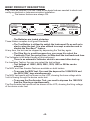
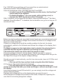
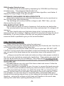
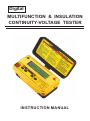
Digital
MULTIFUNCTION & INSULATION
CONTINUITY-VOLTAGE TESTER
INSTRUCTION MANUAL
TABLE OF CONTENTS
Description
Safety Rules............................................................
Safety Checks ........................................................
Don't touch .............................................................
General Description.................................................
Brief Product Description for ..................................
Notes........................................................................
Features...................................................................
Pre-testing Safety....................................................
Operating Instructions..............................................
Inside Lid Instructions 1154TMF ............................
Inside Lid Instructions 1155TMF ...........................
Very Important Automatic Features..........................
Features Comparisons.............................................
Principle of how they work and Results...................
Preparation for use..................................................
Replacing the batteries............................................
Fuse Replacement..................................................
Specifications..........................................................
Limited Warranty.....................................................
Page
01
02
02
03
04-05
06
07-09
09
10-12
13
14
15
16
17-18
19
19
19
20-21
22
SAFETY RULES
CAUTION
RISK OF ELECTRIC
SHOCK
This tester has been designed with your safety in mind. However, no design can
completely protect against incorrect use. Electrical circuits can be dangerous
and/or lethal when lack of caution or poor safety practices are used.
Do not carry out field measurements on either the power system grounding, during
periods of forecast lightning activity, in areas that encompass the station being
measured or of the power network connected to the station being measured. In
the event that lightning occurs, stop all testing and isolate any temporarily installed
test spikes.
Preparations for testing of power system grounding can leave personnel vulnerable
to exposure caused by faults at or fed from the system under test, transferred
potentials from remote test grounds, and inadvertent line energization.
While the probability of the occurrence of one of these events is low, personnel
safety will, nevertheless, be enhanced by the following:
When working near high tension systems rubber gloves and shoes should be worn.
Work on clean, dry crushed rock or an insulating blanket.
Avoid bare hand to hand contact between the tester and extended test leads.
When using the tester with test leads, ensure that they are safe and properly
authorized
Disconnect the tester from any external circuit when checking or changing the
Fuse and/or batteries.
CAUTION
READ THE MANUAL
Follow the instructions in the Manual for every measurement. Read and
understand the general instructions before attempting to use this tester
-1-
SAFETY CHECK
Before using the tester check the condition of the test leads and the fuses.
The test leads must be free of cracks or any damages and must be insulated as
when they were new.
Fuse replacement is described later in this user's manual..
When changing the fuses by removing the cover to access the internal circuitry,
always disconnect the test leads.
When replacing the fuse use only the type specified, HBC fuse, and insert correctly
into the fuse holder.
Always double check the lead connections before making any measurements.
For increased safety, use fused test leads (optional).
DON'T TOUCH
Don't touch exposed wiring, connections or other "Live" parts of an
electrical circuit. If in doubt, check the circuit first for voltage before
touching it.
Do not use cracked of broken test leads.
THIS INSTRUMENT SHOULD ONLY BE USED BY A COMPETENT,
SUITABLY TRAINED PERSON.
REMEMBER
SAFETY IS NO ACCIDENT
CAUTION RISK OF ELECTRIC SHOCK
CAUTION READ THE MANUAL
-2-
GENERAL DESCRIPTION
A new generation of Modern Digital MultiFunction Testers is born.
These Testers have a range of new features not even found in Expensive
Advanced Test Equipments.
They are optimized for Telecommunication and Electrical work.
They test insulation at voltages settings of:
1000V, 500V, 250V, 125V, 100V and 50V.
They are models 1154TMF and 1155TMF.
Not only Rugged, but designed to excel in Harsh environment, still, remaining low
cost and affordable.
They can be operated with rechargeable batteries, alkaline or low
cost general purpose batteries.
This Family of Originally Designed Unique Products have multi-features:
Insulation Resistance Testing, Voltage (ac-dc) measurements with
Automatic Hold facility, Continuity Test with a short circuit current of
Minimum 200mA.
Two very unique features are found on these Multifunction testers;
MOV and Gas Arrester Testing.
Today, most equipments and electrical installations are protected by MOVs and
Gas arresters.
They can test these devices to establish if the devices are still operating correctly
or not.
Energy conservation is featured on all these new Advanced Products.
EnerSaveTM limits the test duration to about 10 Seconds to save
energy.
This new generation of test equipments have no moving parts. All calibration are
saved internally in a non volatile memory.
Calibration can be done at any calibration facility around the world, without the
need for dedicated calibration equipment.
This makes these products easier to maintain and lower the cost
of calibration and ownership.
Their calibration interval can be extended without much problem as vibrations does
not affect the calibration adjustments.
They comply to all the latest regulations, including UK 16Th Edition .
This product family is part of our new World Class series.
They prominently feature heavy duty protections in their circuitry.
The 1155TMF can display the Polarization Index and the Dielectric
Absorption Ratio automatically.
-3-
BRIEF PRODUCT DESCRIPTION
11
54
TM
F
The 1154TMF and the 1155TMF have all the basic features needed to check and
certify an electrical or telecommunication installation.
The buzzer features are always ON.
To Switch Instrument
OFF: DEPRESS for more
than 5 seconds
1000V
500V
250V
125V
IN>1mA
100V
50V
ON/TEST
SCC>220mA
LOW
To AUTO-NULL Test Leads and Fuse
Resistance, DEPRESS Ohm Key again,
while Shorting the Tips together.
AUTO-NULL
AUTO RANGING
AUTO OFF
Continuity Buzzer
is always ON.
EnerSaveTM
PRESS TOGETHER
FOR MOV TEST
PRESS TOGETHER
FOR GAS / NEON TEST
Tc ±1mAdc
CAT
600V
The Batteries are tested at startup.
These testers complies to all good Standards.
The Test Button is utilized to switch the Instrument On as well as to
start or stop the test. It is also utilized to accept a selection and to
disable the EnerSaveTM feature.
At any time, the test can be stopped by depressing the Test key again.
The Ohm Key is a multi-purpose key, you press it to select the
Continuity Test. You press it too, to Auto-mull the test leads and fuse.
The Voltmeter is the default mode of this instrument.
There is an automatic Voltmeter which is accessed after start up.
For Insulation Testing, the user can select the test voltage.
Test Voltage of 1000V, 500V, 250V, 125V, 100V or 50Vdc can be
selected.
The MOV and Gas Arrester Tests are available on both testers.
To access the MOV test, You need the depress the 1000V/500V and
the 250V/120V keys simultaneously.
The MOV test results will be shown on the LCD, showing the knee voltage while
1mA is flowing through the device under test.
To access the Gas Arrester Test, you need to depress the 100V/50V
And the Ohm keys simultaneously.
The Gas Arrester test results will be shown on the LCD, showing the firing voltage
of the device under test.
-4-
11
55
TM
F
The 1155TMF has everything you'll ever want from an electrical and
telecommunication Test and Measuring tool.
It has all the features of the 1154TMF plus the PI and DAR.
TM
In order to use te PI and DAR function on this tester, the EnerSave
mode needs to be disabled.
TM
To disable EnerSave , the user needs, while starting a test, to
depress the TEST key for more than 3 Seconds.
TM
After 3 Seconds, a short beep will be heard, meaning that EnerSave has been
TM
disabled. Once EnerSave is disabled, the test duration can go for as long as 10
minutes (PI test).
To Switch Instrument
OFF: DEPRESS for more
than 5 seconds
PI / DAR
ON - TEST
1000V
500V
250V
125V
IN>1mA
100V
50V
SCC>220mA
LOW
To AUTO-NULL Test Leads and Fuse
Resistance, DEPRESS Ohm Key again,
while Shorting the Tips together.
AUTO-NULL
AUTO RANGING
AUTO OFF
Continuity Buzzer
is always ON.
EnerSaveTM
PRESS TOGETHER
FOR MOV TEST
PRESS TOGETHER
FOR GAS / NEON TEST
Tc ±1mAdc
CAT
600V
Before any test is performed, (provided the test leads are connected properly and
the fuse is intact) it makes a voltage test to assert that there is no voltage on the
device or circuit under test.
If there is a voltage which could be a safety problem for the test, the tester,
automatically, switch to the Voltmeter and shows the voltage on the display. Be it
AC or DC.
If voltage is present on the leads before test is started, the selected test is
cancelled and the keypad is disabled, preventing errors of operation.
This makes this tester one of the safest to operate to date.
Once any voltage is cleared, test can begin. Should you want to measure
Insulation Resistance, you can select by using the test Voltage which can go into
the Giga-Ohm range on the higher voltages settings.
Should you want to test continuity, use the Low ohms scale, down to 0.01Ohm and
also the buzzer.
You can null the fuse and test leads using the Auto-Null feature.
Of Course on this model, Auto-hold is featured.
You will appreciate the superior Safety of Auto-Hold when you
decide to visually look after your arms and fingers without needing to check
the display.
Auto-Hold is always turned ON and with it, you can simply touch the voltage and
remove the test probes.
The last valid voltage will be on the display when you want to see it.
While Dangerous voltages are present on the leads, it beeps too, signaling the
user that he is touching dangerous voltage.
-5-
NOTES
-6-
FEATURES
ON Key.
When Depressing the ON button, the tester starts up. The tester will
automatically make a battery test (under load condition) and display the results.
After that, the voltmeter is automatically selected. If voltage is present, the
tester will automatically display it on the display and disable all other features until
the voltage is removed from the terminals.
Battery Test
There is no battery Key, but a Controlled Load is switched ON automatically
during starting of the tester.
That Load draw some current from the battery.
While drawing that current, the battery voltage is measured and displayed.
To do an other "nder load" battery test, you will need to re-start the tester.
The battery is monitored constantly while the tester is operating. Should the
battery be low, the low battery indicator will lit up on the display.
Voltmeter
There is no Voltmeter Key as this is the default mode of this instrument.
The tester switch to the voltmeter mode after start-up. This is an automatic
AC/DC voltmeter.
This mode is the default mode of the tester, meaning that it's monitoring the
leads before any test is started and also monitoring the leads at Switch ON of the
tester.
The voltmeter is also activated during automatic discharge of circuit after an
Insulation test.
Auto-Hold
Auto-Hold feature is always ON (displays Auto Hold on the LCD), the tester
automatically hold the last valid reading present on the test leads.
This is a very good feature for added safety. That mean that the user can focus on
his test leads and what they are touching instead of looking at the display.
The voltmeter is like an automatic Hold.
This feature has been developed by Toptronic Limited so that the user can
focus on his personal safety first.
The value will be held on the LCD for later reading after the leads are removed
from Dangerous voltage and situations.
1000V, 500V, 250V, 125V, 100V, 50V Insulation Resistance Tests
When an Insulation Resistance Test is selected, the first thing the tester
requires, is for you to connect the leads to the circuit under test. If the circuit is not
voltage free, the tester will go back to the safety voltmeter until you insulate the
circuit under test from any voltage source.
If the circuit under test is voltage free, then you will be asked to confirm that
you want to test it now, then the test will start. You can observe the voltage output
on the bar-graph and see the Insulation resistance results.
Test can be stopped at any time or automatically, according to the type of test
started and the duration you depressed TEST (see EnerSaveTM Mode)
-7-
TEST Key
The Test Key is utilized to start and stop the test.
This is in conjunction with EnerSaveTM.
EnerSaveTM feature
When you depress the TEST key to turn the selected test ON. The tester will
automatically stop the test for you after about 10 Sec, but if you whish to keep the
test running much longer, then depress and keep depressing the TEST key for
more than 3 Seconds, the tester will beep when EnerSaveTM is disabled.
For longer tests duration, every time you start a test, you need to keep depressing
the TEST key for more than 3 Seconds to disable EnserSaveTM. EnerSaveTM is the
default setting of these testers. EnerSaveTM was developed by Toptronic Ltd to help
reduce Consumption by reducing the test duration automatically.
Ohm Key for Continuity Tests
Select the ohm key to make Continuity tests. Continuity test has a short circuit
current of more than 200mA. That range can measure down to 0.01Ohms.
Use this feature with Auto-Null for Convenience.
Auto-Null Key for Continuity Tests (same key as ohm key)
You must depress the ohm key to auto-null the resistance of the test leads and
the resistance of the fuse. Once this is done, that auto-null value is saved internally
and only need to be done if you change the test leads of the fuse. This feature is
very useful when checking Wiring Continuity with long wires. For example when
measuring the continuity of the earth protective wires in a house.
Don't forget to short the test leads together while auto-nulling them.
OFF Key (Auto OFF always present)
The OFF key is a software key which is activated When the 1kV key is
depressed for more than 5 seconds ( provided no test is in progress and everything
is discharged.
The 1kV key, when depressed for more than 5 Sec, will switch the tester OFF,
or stop the test in progress.
In this case, you have to depress 1kV again to turn the tester OFF.
The Tester turns OFF by itself after the programed time
MOV Selection Keys
The MOV test can be accessed by depressing the 1000V/500V and 250V/
125V keys simultaneously.
This select the MOV test.
Make sure that you are testing the correct component before starting this test.
This test starts with a voltage of 0Vdc, then increase that voltage until the
MOV start conducting with 1mA of current.
The Voltage on the MOV, while 1mA is flowing through is displayed on the
LCD as well as the equivalent Max AC voltage which could be utilized on this
device.
-8-
GAS Arrester Selection keys
The GAS test can be accessed by depressing the 100V/50V and Ohm keys
simultaneously. This select the Gas Arrester test.
Very similarly to the MOV test, but using an other algorithm, much faster. It
display the firing voltage of hte gas arrester.
AUTOMATIC DISCHARGE ON INSULATION TESTS
All insulation tests have an automatic discharge which can be monitored on
the LCD bar-graph while discharging.
The discharge will continue until the voltage is safe. ONLY then, you can
disconnect the test leads.
NON DESTRUCTIVE TESTS
All the tests are using a current of maximum 1mA and are non destructive.
The only test which use more than that is the continuity test. It's voltage is 5V
maximum.
The user should make sure that when doing a test, he knows what he is
testing and how he is testing it. Making a sketch of every test will lower the risk of
bad testing. If you are not sure of the test you are going to proceed with, ask
someone which is qualified to give you the correct answers.
PRE-TESTING SAFETY
Always check the fuse before using the instrument.
This is done by shorting the test leads and selecting the Continuity test. Use this, to
null the test leads resistance at the same time.
Always clip securely the leads onto the circuit under test. DO NOT JUST
TOUCH IT as this could make intermittent contact and therefore the safety features
may not work all the times because the connections may not be present at all
times.
Always connect the test leads and make sure they make proper contacts to
the circuit under test before pressing the test buttons. These testers are smart, but
can only be as smart as your connections. That mean that all the safety features
will only work if you have proper connections prior, during and post testing, to the
circuit under Test.
All safety features can only work if the fuse is intact and correct. Follow the
interactive messages on the display.
These testers rely completely on you, the user, to connect the leads securely
onto the circuit under test before starting any tests and before selecting any test.
That mean that from the time you switch the tester ON, you should connect
securely the test leads from the tester's terminals to the circuit under test. When
ever possible, use fused test leads for increased safety. Fused test leads are in
series with the existing internal fuse, so the voltage will be divided on both fuses,
therefore, reducing the voltage on both fuses and therefore in the worst case,
making them safer when opening (breaking the circuit).
-9-
OPERATING INSTRUCTIONS
Leads Connections
The Test Leads are color coded for easy use. These testers only use 2 leads which
are located on both back extremities of the front panel.
The user can vusualy check these connections at any time.
FUNCTIONS
PI / DAR
ON - TEST
EnerSaveTM
When Depressing the "ON-TEST" Button, the instrument
starts up or resets.
Please Note:
If after a test, no key is depressed for ± 5 minutes, the
Instrument will switch off automatically.
AUTO-OFF
To Switch Instrument
OFF: DEPRESS for more
than 5 seconds
1000V
500V
You can turn OFF the Tester without having to wait
for Auto-off. To Turn-Off and switch OFF the Tester
immediately, Depress the 1000/500V key for 5
seconds. If a test is still in Progress, pressing
1000/500V key will stop the test. In this case you
need to press 1000/500V for 5 secretary again.
Batteries are Tested during
start-up of the Tester.
During this Battery Test, a
larger than average current
is drawn. The worst cast
Battery Voltage is seen on LCD.
The Batteries are tested automatically at start up the current
Drawn from the batteries is about 300mA.
While current is drawn, the total battery voltage is
Measured and displayed.
Note that battery voltage is always monitored during use of
the instrument. Should the battery become too low, the low
Battery symbol will be displayed.
Voltmeter ac-dc is
automatically selected after
starting
the tester and if voltage is
present on the test leads
before any test. Follow
instructions on the display.
Ac and Dc voltages are automatically detected and shown.
This is the default function of the Instrument. The Voltmeter
is selected by default by the Instrument. The voltmeter is
activated before any test start and the user must connect
the test leads to any circuit before starting any test.
Voltmeter ac-dc is
automatically selected after
starting
the tester and if voltage is
present on the test leads
before any test. Follow
instructions on the display.
This ensure complete safety to the user and the Instrument.
Should voltage be present on the circuit under Test, this
SAFETY VOLTMETER will warn the user of the danger.
-10-
As ADDED SAFETY, this Auto-Hold helps the user taking
measurement without watching the display. The user can
Focus instead, on it's hands and test leads. AUTO-HOLD is
always enabled, the tester will automatically HOLD the last
valid reading, which mean that when the user touch a
voltage, that voltage is held on the display even after untouching the voltage.
This add great safety for the user as he can focus on it
safety by only looking at the test leads.
VOLTMETER
AUTO-HOLD
Insulation test Voltage selection is done by Depressing the
corresponding key. Depress twice the 1000V/500V for
example to select 500V, similarly for 250V/125V or
100V/50V, etc ...
To Switch Instrument
OFF: DEPRESS for more
than 5 seconds
PI / DAR
ON - TEST
1000V
500V
250V
125V
IN>1mA
100V
50V
SCC>220mA
LOW
To AUTO-NULL Test Leads and Fuse
Resistance, DEPRESS Ohm Key again,
while Shorting the Tips together.
AUTO-NULL
AUTO RANGING
AUTO OFF
Continuity Buzzer
is always ON.
EnerSaveTM
PRESS TOGETHER
FOR MOV TEST
Tc ±1mAdc
PRESS TOGETHER
FOR GAS / NEON TEST
CAT
600V
EnerSaveTM
EnerSaveTM is a Smart Program which Save Energy when
ever possible by limiting the Test Duration.
PI= Polarisation
Index
PI: this is the ratio of the Insulation Resistance at 10 Min
divided per the Insulation Resistance at 1 Minute.
DAR = Dielectric
Absortpion
Ratio
DAR: this is the ratio of the Insulation Resistance at 1 Min
divided per the Insulation Resistance at 30 Seconds.
SCC>220mA
LOW
To AUTO-NULL Test Leads and Fuse
Resistance, DEPRESS Ohm Key again,
while Shorting the Tips together.
Select the Continuity test which has
AUTO RANGING a Short Circuit Current of 200mA. It
Complies to all latest standards.
AUTO OFF
Continuity Buzzer
AUTO-NULL
is always ON.
AUTO-NULL
Continuity Buzzer
is always ON.
Auto-Null the resistance of the test leads and of the fuse
so that continuity measurements can show only the
resistance under test.
Buzzer is always On. Low resistance value BEEP when low.
It's helping when tracing circuitry.
-11-
Pressing the 1000V/500V and 250V/125V keys simultaneously will select the MOV
Test.
1000V
500V
250V
125V
IN>1mA
PRESS TOGETHER
FOR MOV TEST
Tc ±1mAdc
Today's new Equipments and Electrical Installations are generally Protected by
MOVs.
It is now easy to test these devices to ensure their proper working and replace
them if found damaged. The knee Voltage is shown on the display.
Pressing the 100V/50V and W keys simultaneously will select the Gas Arrester test
Function.
100V
50V
SCC>220mA
To AUTO-NULL Test Leads and Fuse
Resistance, DEPRESS Ohm Key again,
while Shorting the Tips together.
LOW
AUTO-NULL
AUTO RANGING
AUTO OFF
Continuity Buzzer
is always ON.
PRESS TOGETHER
FOR GAS / NEON TEST
CAT
The Trigger Threshold Voltage is shown on the LCD.
All Gas protection devises can be Tested, including Neon Lights.
-12-
600V
-13-
Voltmeter is automatically activated if Voltage on
the leads is >5V, before any test is started.
When Tester is starting, the voltmeter Ac and Dc
is activated.
This is the default function of the
Instrument.
The voltmeter is activated before any test starts
and the user must connect the test leads to any
circuit before starting any test. This ensures
complete safety to the user
and the Instrument. Should voltage be present
on the circuit under Test, this SAFETY
VOLTMETER will warn the user of the danger.
Continuity Key
Test (0.01 to 1999 ).
Press again to Auto-Null Leads and Fuse
resistance.
The auto-null value is saved in memory.
ON-TEST Key
When Depressing the “ON-TEST” Button, the
Instrument starts up, then Tests and Displays
the Battery Voltage or Resets.
Starts or Stops Insulation Test and AutoDischarge.
1000V/500V, 250V/125V, 100/50V Key
Depress key to select wanted Insulation Test
Voltage. To switch OFF Instrument, Depress
1000V/500V key for > 5S (after testing has
stopped) .
Test Varistors or MOVs
The Knee DC voltage is indicated when Current
in the device reaches 1mA.
Test Striking voltage of Neon Lights
and Gas Arresters. Only up to 1000V.
Voltmeter with Automatic Hold
Auto-Hold helps the user taking
measurements without looking at the display.
The user can focus on its hands and test leads
instead.
AUTO-HOLD will auto-matically HOLD the
last valid reading, the voltage is held on the
display after un-touching the voltage.
EARTH= -Voltmeter Lead
LINE = + Voltmeter Lead
EARTH= - Continuity Lead
LINE = + Continuity Lead
EARTH= - Insulation Test Lead
LINE = + Insulation Test Lead
INSTRUCTIONS
DIGITAL MULTIFUNCTION TESTER
MF
4T
5
11
INSIDE LID INSTRUCTIONS
1154TMF
-14-
Voltmeter is automatically activated if Voltage on
the leads is >5V, before any test is started.
When Tester is starting, the voltmeter Ac and Dc
is activated.
This is the default function of the
Instrument.
The voltmeter is activated before any test starts
and the user must connect the test leads to any
circuit before starting any test. This ensures
complete safety to the user
and the Instrument. Should voltage be present
on the circuit under Test, this SAFETY
VOLTMETER will warn the user of the danger.
Continuity Key
Test (0.01 to 1999 ).
Press again to Auto-Null Leads and Fuse
resistance.
The auto-null value is saved in memory.
ON-TEST Key
When Depressing the “ON-TEST” Button, the
Instrument starts up, then Tests and Displays
the Battery Voltage or Resets.
Starts or Stops Insulation Test and AutoDischarge.
1000V/500V, 250V/125V, 100/50V Key
Depress key to select wanted Insulation Test
Voltage. To switch OFF Instrument, Depress
1000V/500V key for > 5S (after testing has
stopped) .
Test Varistors or MOVs
The Knee DC voltage is indicated when Current
in the device reaches 1mA.
Test Striking voltage of Neon Lights
and Gas Arresters. Only up to 1000V.
Voltmeter with Automatic Hold
Auto-Hold helps the user taking
measurements without looking at the display.
The user can focus on its hands and test leads
instead.
AUTO-HOLD will auto-matically HOLD the
last valid reading, the voltage is held on the
display after un-touching the voltage.
EARTH= -Voltmeter Lead
LINE = + Voltmeter Lead
EARTH= - Continuity Lead
LINE = + Continuity Lead
EARTH= - Insulation Test Lead
LINE = + Insulation Test Lead
PI = POLARISATION INDEX = R@10MIN / R@1MIN
INSTRUCTIONS
DIGITAL MULTIFUNCTION TESTER
DAR = DIELECTRIC ABSORPTION RATIO = R@1MIN/R@30Sec
MF
5T
5
11
INSIDE LID INSTRUCTIONS
1155TMF
VERY IMPORTANT AUTOMATIC FEATURES
Automatic Vac-dc Detect.
All of these testers in this family have the capability to detect Voltage AC and DC.
This is done with the use of the internal safety voltmeter which does this work.
However, this feature will only work if the test leads are securely connected to the
circuit under test.
So, you must ensure that the lest leads are doing a perfect contact before
beginning any test and before selecting any function. That contact must remain
secure during the entirety of the tests on a particular circuit.
We recommend you to use clip-on alligators and not the tips only, so that you can
make sure the test leads are making a proper contact during the all duration of the
tests.
Should the test leads not make contact at any time before, during and after the test,
all the safety features of these testers will not functions.
It's your responsibility to ensure proper contact of the leads at all times.
Automatic Discharge of Capacitive and inductive Circuits
These testers will discharge automatically all circuits charged by the tester, after a
test is done, again, this will only be activated if the test leads make contact at any
time before, during and after the test.
It's your responsibility to ensure proper contact of the leads at all times.
Once a test is finished, the testers will automatically discharge capacitive or
inductive circuit of their charge. The discharge can be observed on the display, in
the form of a bar-graph. Again, do not disconnect the leads while discharge. Wait
until completion of the discharge before removing any lead.
During Discharge, the Buzzer will beep and the bar-graph will show some voltage.
With some high charges, this may takes some time. Be patient and let the
instrument discharge completely before proceeding to removing the leads.
Auto-off
This family of instruments has an Auto-off feature which will switch off the tester,
should no key or function be in use. Please, again, note that if voltage is present on
the leads, the instrument will warn the user of that and the auto-off feature will be
inactive until dangerous voltage has been removed from the circuit.
-15-
FEATURES COMPARISON
1154TMF
1155TMF
Test Battery at Start
Test Battery at Start
Automatic
Automatic
Always ON
Always ON
EXTRA INSULATION ELECTRICAL TEST VOLTAGES (125, 250)
TELECOMMUNICATION TEST VOLTAGES 50V and 100V
Automatic Voltmeter AC/DC at Start / Reset
ON-Reset/Restart Key
Off Push Button (press more than 5 Sec on 1kV key) and AUTO-OFF
Large range of insulation test voltages: 50, 100, 125, 250, 500, 1000V
MOV / Protection Devices Test
Test ON-OFF
Polarization Index (PI) on 50, 100, 125, 250, 500 and 1000V
Dielectric Absorption Ratio (DAR) on 50, 100, 125, 250, 500 and 1000V
Battery Test by Key
Battery Test at Switch ON / Reset
Voltmeter on request by Keypad
Safety Voltmeter before each Test
Auto-Discharge on all Test and all Ranges
Continuity Short Circuit Current >220mA ( 225mA Typical )
Continuity Open Circuit Voltage of 5V dc
Nominal Voltage @ 1mA on all Insulation Ranges
Buzzer ON/OFF by Key
Leads Auto-Null key
Test Auto-Stop
Display Customization for OEM
Re-programmable Microprocessor for Easy Updates
Can be calibrated in ALL calibration laboratories
Insulation measurement from 2k
Continuity from 0.01
(250V range) to 8G
(1kV Range)
(220mA) to 1999
DC Voltmeter from ±1Vdc to ±950Vdc
AC Voltmeter from ±1Vac to ±700Vac
Accept 8 Rechargeable Batteries or Alkaline or Normal
Smart Hold & Stop on Voltmeter ac / dc
Gas Arrester Function
EnerSaveTM
-16-
PRINCIPLE OF HOW THEY WORK AND RESULTS
This family if Test instruments operate through a keypad interface. The number of
keys and their function are different on each model. All interactions between the
user and the instrument is done via the keypad.
The testers have a liquid Crystal Display and two or three terminals.
Each push button or key has a function.
DIGITAL DISPLAY
The digital Liquid Crystal Display is large. It measures (W)98mm x (H)24mm and
has a 2Lines of 16 Characters.
Language can be changed on demand.
Dutch / French / German etc... (factory fitted at order)
FUSED
The tester is fused by a fast blow 500mA fuse.
CROWBAR PROTECTION
In case of misuse, a crowbar is integrated and will blow the fuse.
This crowbar will reduce the damages in case of user mistake.
The crowbar is activated at less than 6V (ac or dc).
AUTOMATIC BATTERY TEST
When the tester starts, it test it's batteries by drawing a heavy current from the
batteries. During that heavy current, it measures the battery voltage and display it
for a few seconds on the display.
During normal use, the tester monitor the battery voltage, but without drawing a
battery test current. It just measure the battery while in normal use.
SAFETY VOLTMETER
Once the battery test is terminated, the tester goes automatically into the
Voltmeter mode. It has an Automatic voltmeter AC and DC.
The safety voltmeter even has a Hold function built-in.
The Hold Function will automatically put the last valid reading on hold if the user
disconnect the leads.
This is a safety feature, where the user does not need to observe the display but
instead observe where he has his hands and probes. This way, safety is increased.
The Safety Voltmeter works up to Vdc 900V (both polarities) with resolution of 1V
and 1% accuracy. It also measure up to Vac 700V, with the same resolutions and
accuracies.
INSULATION
It has six insulation test Voltages. 50, 10, 125, 250, 500 and 1000V, all of theses are
capable of giving more than 1mA at their nominal voltages.
50V range can measure from 0.1M ohms up to 400M ohms
100V range can measure from 0.1M ohms up to 800M ohms
125V range can measure from 0.1M ohms up to 1G ohms
250V range can measure from 0.2M ohms up to 2G ohms
500V range can measure from 0.2M ohms up to 4G ohms
1000V range can measure from 0.2M ohms up to 8G ohms
On 1155TMF it automatically calculates the PI and DAR and has an automatic timer.
-17-
CONTINUITY
The continuity test has an open circuit voltage of exactly +5Vdc regulated.
The Short Circuit Current of the continuity circuit is about 220mA.
The Continuity test can measure from 10 milli- ohm (0.01) up to 2Kohms.
The accuracy is better than 1% of reading from 1 ohms to 200 ohms, plus minus
one digit.
Below 1 ohms, it's better than 5% of readings plus minus 3digits.
Above 200 ohms, up to 1999 ohms, it's better than 3% of readings plus minus 3
digits.
The Continuity has an auto-nulling facility which is saved into non volatile memories,
so you only need to null the leads of fuse again if they are changed.
AUTO-OFF
They have an auto-off feature and the power automatically turn off after 5 minutes of
inactivity.
EnerSave
The battery life can be saved when the user make spot check.
To make a spot check, the user only press the test button for less than 3 seconds,
or use the Quick Test key.
If the user press the test key for more than 3 seconds, the tester make a long test
(timer enabled up to 10 minutes for PI test ).
Any test can be stopped at any time.
SAFE VOLTMETER DETECTION
On any of the tests, if the user connect the leads to a voltage, prior to starting the
test, te tester will detect the voltage and automatically turn the Voltmeter ON as well
as an alarm. All other test facilities are disabled when this happen.
DIGITAL CALIBRATION
This family of testers are digitally calibrated. That mean that there have no
potentiometers or moving part in this product. All the correction factors are saved
into the internal memory.
BATTERIES
The testers can work with 8 x 1.5V batteries.
The user can also use rechargeable batteries in the same product.
-18-
PREPARATION FOR USE
Fuses:
In doubt, check the fuses using a ohm meter.
Please note that this instrument will not indicate anything, should the fuses be
blown.
Please note that this instrument will be unsafe if the fuse is blown as no indication
will be shown and nothing will be detected by it.
For that reason, you must verify the fuse Before and after any test.
Test Leads:
Check the test leads for defects or cracks. Replace if cracked or damaged. Only
replace with the same type. Use the Continuity test to check, with the fuse(s), that
the complete circuit is in good condition.
Cleaning:
Use a damp cloth to clean the case. Do not use chemicals
REPLACE THE BATTERIES
This instrument operate well with Alkaline 1.5V or rechargeable 1.2V batteries. It
could be operated with inferior batteries too. It use 8 of them. To replace the
batteries, disconnect the test leads, then unscrew the bottom battery cover and
replace the batteries.
DISPOSING OF BATTERIES
Only dispose of batteries into a purposely dedicated disposal system. Do not
dispose to the wrong place. Look after your environment, please.
FUSES REPLACEMENT
Unscrew the back cover and replace the faulty fuse with the same
type, then screw the cover back into place correctly
-19-
SPECIFICATIONS
GENERAL
Load Battery Test Current.....................................
Battery Voltage Display Accuracy.........................
About 300mA
±0.5V
BATTERIES
Type alkaline.........................................................
Other Type............................................................
Quantity.................................................................
1.5V
1.2V
8
DISPLAY
Type......................................................................
LCD 2 lines x 16 Characters
AUTO-OFF
Automatic Turn OFF Time after last action...........
5Min.
VOLTMETER (3 minutes maximum)
Automatic Voltage DC Range...............................
Automatic Voltage AC Range...............................
Resolution on both voltage types..........................
Accuracy on both voltage types............................
0 to 950Vdc
0 to 700Vac
±1V
±1.5% of FS
INSULATION TEST
Resistance Range
50V Test Voltage...................................................
100V Test Voltage.................................................
125V Test Voltage.................................................
250V Test Voltage..................................................
500V Test Voltage.................................................
1000V Test Voltage...............................................
Accuracy on all ranges.........................................
When Voltage is constant, Current is
Software Limited at...............................................
Short Circuit Current on all ranges
Maximum Short Circuit Current............................
Polarization Index
Ratio Resolution....................................................
Ratio Accuracy......................................................
Dielectric Absorption Ratio
Ratio Resolution....................................................
Ratio Accuracy......................................................
Fast Test
Test Duration with EnerSave Enabled..................
Long Test
Test Duration without EnerSave Enabled.............
With PI and DAR test Function.............................
-20-
0.1M - 400M Ohms
0.1M - 800M Ohms
0.1M - 1G Ohms
0.2M - 2G Ohms
0.2M - 4G Ohms
0.2M - 8G Ohms
4G ~8G
±5% rdg
0.1M ~4G
±3% rdg
±1.2mA
±4mA.
±0.1
±1% of Rdg
±0.1
±1% of Rdg
10Sec
60Sec.
10Min.
CONTINUITY TEST
Short Circuit Current Test.............................
Open Circuit Voltage....................................
Continuity Range( Ohms).............................
Continuity Accuracy 0.01 to 100 Ohms........
Continuity Accuracy 100 to 300 Ohms.........
Continuity Accuracy 300 to 1999 Ohms.......
Continuity Resolution...................................
>220mA
5Vdc
0.01-1999
±1% of Rdg
±1.5% of Rdg
±2% of Rdg
±2 Counts
AUTO-NULL
Auto-Null Value Saved in no volatile Memory
Auto-Null Threshold......................................
5 Ohms
BUZZER
Buzzer Threshold..........................................
3 Ohms
MOV TEST
Test Voltage.................................................
5-1020Vdc
Voltage Results Accuracy............................
±3%
Voltage Result Resolution...........................
±2 Counts
Measure the Threshold Voltage Calculate the approximate Vac Marking on the
MOV (depend on manufacturer)
Contact [email protected] for more details on this function.
GAS ARRESTER TEST
Test Voltage..........................................
5-1020Vdc
Voltage Results Accuracy......................
±3%
Voltage Result Resolution.....................
±2 Counts Measure the Threshold
Voltage.
Contact [email protected] for more details on this function.
PROTECTIONS
OverLoad..............................................
Over Voltage ........................................
Fuses....................................................
600V (between all terminals)
Class
- 600V towards ground.
1 x 500mA / 250V, 5 x 20mm
MECHANICAL
Size......................................................
Material................................................
Weight .................................................
Display..................................................
250 x 190 x 110 (mm)
Polycarbonate /A BS
Approx. 630g (Battery included)
Liquid Crystal Display
ENVIRONMENTAL
Operating temperature Range:
Storage Temperature:
1 °C to + 55 °C not in full sun!!!!
-20 °C to + 70°C
CLEANING
Clean the instrument case with an anti-static cleaner and wipe with dry cloth.
-21-
LIMITED WARRANTY
We warrant the product manufactured by us to be free from defective
material or factory workmanship and agree to repair or replace this
product which, under normal use and service, disclose the defect to be
the fault of our manufacturing, with no charge for parts and service. If we
are unable to repair or replace this product, we will make a full refund of
the purchase price.
Consult the user's manual for proper instruction regarding use of this
instrument.
Our obligation under this warranty is limited to repairing, replacing or
making refund of this test equipment which proves to be defective within
TWELVE months from the date of original purchase.
This warranty does not apply to any of our products which have been
repaired or altered by unauthorized persons in any way so as, in our sole
judgement, to injure their stability or reliability, or which have been
subject to misuse, abuse, misapplication, negligence or accident or which
have had the serial numbers altered, defaced or removed.
Accessories, not of our manufacture used with this product, are not
covered by this warranty.
All warranties implied by law are hereby limited to a period of TWELVE
months, and the provisions of the warranty are expressly in lieu of any
other warranties expressed or implied.
The purchaser agrees to assume all liability for any damages or bodily
injury which may result from the use or misuse of the product by the
purchaser, or it's user, his employees, or others, and the remedies
provided for in this warranty are expressly in lieu of any other liability we
may have including incidental or consequential damages.
We reserve the right to discontinue models at any time, or change
specification, price or design, without notice and without incurring any
obligation.
M54.M55
-22-