1
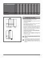
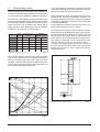
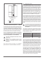
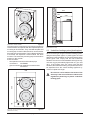
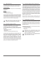
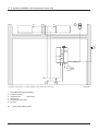
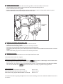
CE PIN 0063AS3538 INSTALLATION & SERVICING INSTRUCTIONS 8G.51.28.01/04.03 We reserve the right to make changes These instructions to be retained by user. Contents 1 2 3 4 5 6 7 8 9 10 11 12 13 14 15 16 17 18 19 20 Introduction ................................................................................................................................................. 4 Regulations ................................................................................................................................................. 4 Description of the appliance ........................................................................................................................ 5 Scope of the supply .................................................................................................................................... 5 Mounting of the boiler .................................................................................................................................. 5 5.1 Dimensions ....................................................................................................................................... 6 Connecting the boiler .................................................................................................................................. 7 6.1 Central heating system ..................................................................................................................... 8 6.2 Expansion vessel .............................................................................................................................. 9 6.3 Underfloor heating systems (plastic pipes) ....................................................................................... 10 6.4 Gas connection ................................................................................................................................ 10 6.5 Hot water supply (S-HR-T) ................................................................................................................ 11 6.6 Hot water supply S-HR 15, 24 and 35 .............................................................................................. 11 6.7 Condensation drain pipe ................................................................................................................... 11 6.8 Flue gas exhaust system and air supply system ............................................................................. 12 External hot water cylinders ....................................................................................................................... 14 Electrical connection .................................................................................................................................. 14 Boiler controls ............................................................................................................................................ 16 9.1 Explanation of the function keys ...................................................................................................... 16 Filling and venting the boiler and installation ............................................................................................... 17 10.1 Central heating system .................................................................................................................... 17 10.2 Hot water supply .............................................................................................................................. 17 Commissioning the boiler .......................................................................................................................... 18 11.1 Central Heating system .................................................................................................................... 18 11.2 Hot water supply .............................................................................................................................. 18 11.3 Adjustments .................................................................................................................................... 18 Isolating the boiler ...................................................................................................................................... 21 Commissioning .......................................................................................................................................... 22 13.1 Checking for contamination .............................................................................................................. 22 13.2 Checking of the zero pressure control .............................................................................................. 22 13.3 Checking the CO2 ............................................................................................................................ 23 Maintenance .............................................................................................................................................. 24 14.1 The frequency of maintenance .......................................................................................................... 24 14.2 Maintenance activities ...................................................................................................................... 24 14.3 Further checks ................................................................................................................................. 24 Technical specifications ............................................................................................................................. 25 Diagram showing various parts of the boiler ................................................................................................ 26 Example diagrams for connecting the boiler ............................................................................................... 28 17.1 Radiator installation without thermostat valves .................................................................................. 28 17.2 radiator installation with thermostat valves only ................................................................................ 29 Error indication ........................................................................................................................................... 30 CE-Certificate United Kingdom ................................................................................................................... 31 CE-Certificate Ireland ................................................................................................................................. 32 The appliance should only be installed by a Competent Gas Installer. Installation instructions S-HR series page 3 1 Introduction These instructions describe the functioning, installation, use and primary maintenance of ATAG central heating units for United Kingdom and Ireland. Where necessary different regulations of each country are separately described. These instructions are intended for the use of Corgi registerd installers or registered Bord Gais installers in connection with the installation and putting into operation of ATAG units. It is advisable to read these instructions thoroughly, well in advance of installation. Separate instructions for use are supplied with the unit for users of ATAG central heating units. ATAG is not liable for the consequences of mistakes or shortcomings which have found their way into the installation instructions or user’s manual. Further, ATAG reserves the right to alter its products without prior notification. When delivering the unit, give the customer clear instructions concerning its use; present the customer with the user’s manual and card. Each unit is fitted with an identification plate. Consult the details on this plate to verify whether the unit is compliant with its intended location, e.g.: gas type, power source and exhaust classification. On completion of the installation the installer or commissioning engineer must fill out and complete the Benchmark commission section of the boiler log book and hand to customer or end user for future record keeping. The Benchmark log book must also be filled out and completed by the service agent following each service call, and returned to the customer. A copy of the Benchmark commissioning certificate must be returned to ATAG Heating UK Ltd along with the warranty registration card to register the appliance for the standard warranty benefits. 2 Regulations The following regulations apply to installation of ATAG central heating units: Legislation and Regulations. Gas Safety (Installation and Use). All gas appliances must by law, be installed by a competent person, eg. Members of CORGI and in accordance with the current Gas Safety Regulation. Failure to install appliance correctly could lead to prosecution. In addition to the above regulations this appliance must be installed in compliance with the current IEE Regulations, the Building Standards (Scotland Consolidation) Regulations. Regulations and bye laws of the Local Water Authority and the Current Health and Safety Regulation. Installation instructions S-HR series page 4 Ireland: - Irish standard 813 - Domestic gas installations The current, Electricity at Work Regulation must be complied with and also be in accordance with the relevant and current editions of the British Standards. The ATAG Blauwe Engel boiler is a certified appliance and must not be modified or installed in any way contrary to this Installation Manual. Manufactures instructions must not be taken in any way as overriding statutory obligations. The ATAG Blauwe Engel is a central heating unit with an optional integrated hot water function. These units must be connected according to these instructions and all installation norms in respect of the part of the unit to be connected. Observe the following rules of safety: - All work on the unit must take place in a dry environment. - ATAG units may never be in operation without their housing, except in connection with maintenance or adjustments (see Chapter 13 and 14). - Never allow electrical or electronic components to come into contact with water. Carry out the following tasks in connection with maintenance, etc. to an already-installed unit: - Shut down all programmes - Close the gas tap - Remove the plug from the wall socket - Close the stop cock of the unit’s intake connection Take note of the following when maintenance or adjustments are needed: - The unit must be able to function during these activities; for this reason, the unit’s supply voltage, gas pressure and water pressure must be maintained. Ensure that these are not a source of potential danger during these activities. Following maintenance or other activities; always check the installation of all parts through which gas flows (using leak-search spray). Following maintenance or other activities, always replace the housing and secure it with the screw behind the door at the front of the casing. The following (safety) symbols may be encountered in these installation instructions and on the unit: will only have to switch on once an hour. In this case the aim is to obtain maximum comfort and efficiency. This symbol indicates that the unit must be stored away from frost. In order to be able to anticipate installation heat emissions the boiler has been fitted with a proportional gradient control system. After the boiler goes into operation this control provides a uniform increase of power, instead of immediately burning at full power. When the installation does require full power the control will adjust as required. By this means a uniform increase of the water temperature is effected. If an outside sensor is connected, the control will operate weather-dependent. This means that the control measures the outside temperature and the flow water temperature. On the basis of this data the control calculates the optimal flow water temperature in the installation. This symbol indicates that the packaging and/or contents can be damaged as a result of insufficient care taken during transport. This symbol indicates that, whilst still in its packaging, the unit must be protected from weather conditions during transport and storage. KEY-symbol. This symbol indicates that assembly or dismantling, must be carried out. ATTENTION symbol. This symbol indicates that extra attention must be paid in connection with a particular operation. The S-HR-T combination boiler provides a hot water supply by means of a high output cylinder fitted on the right hand side of the boiler. An adjustable thermostatic mixing valve is fitted which provides a constant hot water temperature (60°C factory setting). Danger: High Voltage! 3 Description of the appliance The ATAG Blauwe Engel S-HR boiler is a room sealed, condensing and modulating central heating boiler, with or without an integrated hot water facility. The built-in fan sucks the combustion air from outside and provides full premixing of the gas and air. The gas mixture is guided through the ceramic burner which is fitted above the heat exchanger. As a result of the small flame height a compact construction is possible. The combustion gasses are exhausted after passing through the stainless steel heat exchanger. The formed condensate water is discharged through the waste trap. The boiler has been tested according to valid CE* standards and has a CE* certificate and SEDBUK Arating. The operating efficiency of the boiler is higher than 98% (on upper value Hs). As a result of its compact construction the radiation, convection and stand by losses are very low. The emission of damaging substances is far below the standard set for equipment with the gas quality-control label for clean combustion. The boiler is provided with an automatic venting program. In case of a recently topped up or filled up installation this program takes care of the removal of any present air in the boiler. In this case the control will check the water pressure and if it is to low, will report this on the display. 4 Scope of the supply The boiler is supplied ready for use. The supply kit is composed as follows: - Boiler with casing; - Automatic vent (inside the boiler); - Safety valve (inside the boiler); - Suspension bracket - Filling and draining valve with T-piece; - Fixing material consisting of plugs and screws; - Template on the package wrapper; - Installation instructions - Operating manual; - Warranty card; - Benchmark logbook. 5 Mounting of the boiler The boiler can be mounted practically to any wall with the suspension bracket and the enclosed fixing equipment. The wall must be flat and of sufficient strength in order to be able to carry the boiler weight. Above the boiler there must be at least 250 mm working space in order to be able to fit a coaxial flue system or a twin supply. On the left side of the boiler at least 50 mm and on the right side 10 mm must be reserved in connection with fitting or removing of the casing. The location of the boiler can be determined by using the template located inside the boiler packaging. The boiler anticipates the heat requirement of the central heating installation or the hot water supply. As a result the boiler will adjust its capacity to the installation and will switch on less often, which means that the boiler will operate longer and at a low level. It is possible that the boiler Installation instructions S-HR series page 5 5.1 Dimensions type of unit A height mm S-HR 15 S-HR 24 S-HR 24T S-HR 35 S-HR 35T S-HR 51 S-HR 51T S-HR 60 680 680 680 680 680 680 680 680 B w idth mm 500 500 840 500 840 660 1000 660 C depth mm 370 370 370 370 370 370 370 370 D left side / flue gas concentric mm 335 335 335 335 335 495 495 495 centre to centre / flue gas exhaust mm and supply 120 120 120 120 120 120 120 120 E F back / flue gas exhaust mm 270 270 270 270 270 270 270 270 G left side / gas pipe mm 65 65 65 65 65 65 65 65 H left side / flow pipe mm 185 185 185 185 185 185 185 185 J left side / return pipe mm 285 285 285 285 285 445 445 445 K left side / condensation pipe mm 370 370 370 370 370 530 530 530 L left side / expansion tank pipe mm 430 430 590 M left side / cold w ater pipe mm 725 725 885 N left side / hot w ater pipe mm 795 955 P left side / return pipe DHW mm 795 475 475 475 Q pipe lenght of g* mm 18 18 18 18 18 18 18 18 R pipe lenght of c and k* mm 40 40 40 40 40 40 40 40 S pipe lenght of f; r; e and w * mm 60 60 60 60 60 60 60 60 T back / centre of pipe c* mm 25 25 25 25 25 25 25 25 U back / centre of pipe g* mm 40 40 40 40 40 40 40 40 V back / centre of pipe f; r; e; k; w * mm 50 50 50 50 50 50 50 50 table 1 Dimensions (* see figure 2) B C B D F D E 50 S RQ A wall wall 10 minimum 250 mm ceiling SRQ G G H J K J L M T U V H K L P N Dimensions (in mm) Installation instructions S-HR series page 6 figure 1 type of unit combustion air supply/flue gas exhaust mm gas pipe - g S-HR 15 S-HR 24 S-HR 24T S-HR 35 S-HR 35T S-HR 51 S-HR 51T S-HR 60 80/125 80/125 80/125 80/125 80/125 80/125 80/125 80/125 ½" inside ½"inside ½" inside ½" inside ½" inside ¾" inside ¾" inside ¾"inside central heating flow pipe - f mm 28 28 28 28 28 35 35 35 central heating return pipe - r mm 28 28 28 28 28 35 35 35 24 24 24 24 24 24 condensation discharge pipe - c mm 24 24 expansion vessel pipe - e mm 22 22 cold w ater pipe - k mm hot w ater pipe - w mm return pipe DHW - d mm 22 15 15 28 28 22 15 15 15 15 28 table 2 connection diameters 6 g f r c e Connecting the boiler The boiler has the following connection pipes; - The central heating pipes. These can be connected to the installation by means of compression fittings; - The gas pipe. It is provided with a female thread into which the tail piece of the gas valve can be screwed; - The condensation drain pipe. It consists of an oval 24 mm plastic pipe. The drain pipe can be connected to this by means of an open connection. If the open connection is fitted in a different location, then the pipe can be lengthened by means of a 32 mm PVC sleeve; - The flue gas exhaust system and air supply system. It consists of a concentric connection 80/125 mm. - Cold and hot water pipes. These consist of 15 mm copper pipe and can be connected to the installation by means of compression fittings. k w When removing the plastic sealing caps from the pipes, contaminated testing water can be released. g f boiler pipes bottom r c ed figure 2 It is advisable to spray-clean all of the unit’s connecting pipes and/or to spray-clean/blowclean the installation before connecting it to the unit. Installation instructions S-HR series page 7 6.1 Central heating system The boiler pipes can be connected to the installation by means of compression fittings. Reducers should be used for connecting to thick-walled pipe (welded or threaded). The boiler has a self-adjusting and self-protecting control system for the load and the pump capacity. By this means the temperature difference between the flow and return water is checked. The circulation pump will be able to supply the given water displacement with an installation resistance of up to 20 kPa, for this see table 3. Pump w ater flow rate permissible UPER l/min l/h kP a mbar 20-60 9,5 570 42 420 15,1 908 30 300 ype installation of unit Iftthe than DTis 20higher °C insthe tallatstated ion resisvalue tance typresistance e S-HR 15 S-HR 24/24T 20-60 S-HR 35/35T 20-60 22,1 1324 20 200 S-HR 51/51T 20-70 32,1 1924 25 250 S-HR 60 37,8 2267 20 200 20-70 If an unacceptable temperature is detected, then the control will repeatedly try to achieve water flow, and if this does not work then the boiler will switch off. The S-HR 60 boiler has a circulation pump which has a residual suction head for the installation of 20 kPa. This means that the boiler can function normally in installations which have an installation resistance of up to 20 kPa and in cascade installations. If the installation resistance is higher than 20 kPa, the boiler will automatically reduce in power. If the capacity of the boiler pump is insufficient, an extra external pump can be installed in series with the boiler. The electrical side of this external circulation pump can be connected in the Control Tower, by which means this pump switches at the same times as the boiler pump. The maximum absorbed current consumption of the external circulation pump may be 230 W (1 Amp). Use with a low velocity header can also be selected. In this case a larger secondary sided water output has to be taken into account, in order to affect the maximum water temperature. table 3 available water flow at full load the pump will rotate at maximum pump capacity and the load will be adjusted until an acceptable temperature difference between flow and return water has been obtained. If, after this, the temperature difference remains to much then the boiler will switch itself off and wait until an acceptable temperature has arisen. 25 % S-H R2 4T 10 0% U 25 PER % 20 -60 UP ER 20 -7 0 i, 3 5T i S-H R1 5, 24 ,3 5 SHR 51 STi HR 51 ,6 0 100% UPE R 20 -70 H(m) UP ER 20 -6 0 external installation pump in series Q(m³/h) pump index lines Installation instructions S-HR series page 8 graph 1 figure 3 6.2 Expansion vessel All ATAG Blauwe Engel S-HR-24T and 35T boilers are provided with an expansion vessel on top of the cylinder. This expansion vessel is connected to the three-way valve and the circulation pump. By this means the expansion water, when functioning for the hot water supply, is prevented from being shut off from the expansion vessel when the radiator thermostat valves are fully closed. The ATAG Blauwe Engel S-HR 51T is provided with a expansion vessel connection. The expansion vessel of correct size must be connected to this pipe. A second expansion vessel in the installation is not a problem. The ATAG Blauwe Engel S-HR boilers are not equipped with an expansion vessel connection. If a S-HR boiler is combined with an Comfort cylinder, the expansion vessel connection is included in the internal piping of the Comfort cylinder, to which the expansion vessel can be connected. If a different cylinder is used then one has to take into account that the expansion vessel should be connected between the three-way valve and the boiler circulation pump. external installation pump with low velocity header figure 4 As standard the boiler is provided with a water filter in the return pipe of the boiler. With this, possible contamination of the central heating water is prevented from ending up in the boiler. The boiler is also provided with an internal safety valve set at 3 bar. This is connected to the waste discharge together with the condensation discharge. If all, or a large part of the radiators are provided with thermostatic radiator valves it is advisable to use a pressure difference control (bypass) in order to prevent flow problems in the installation. The boiler is designed to be used on sealed system only. Additives in the installation water are only permitted in consultation with the country distributor. When using more than one boiler in an installation please refer to the cascade installation instructions. In connection with correct functioning of the boiler it is necessary for the expansion vessel to be connected to the expansion vessel pipe of the boiler. The expansion vessel which is used should be geared to the water content of the installation. The pre-charge pressure depends on the installation height above the mounted expansion vessel. in stallatio n h eig h t ab o ve th e exp an sio n vessel p re-ch arg e p ressu re o f th e exp an sio n vessel 5m 0,5 bar 10 m 1,0 bar 15 m 1,5 bar choice of expansion vessel table 4 The ATAG S-HR24 and S-HR35 boilers can be provided with an expansion vessel module. By this means the external expansion vessel is cancelled. This expansion vessel module is placed behind the S-HR boiler, by which means the expansion vessel is not noticeable. If the S-HR boiler is provided with a ATAG Comfort cylinder the overall depth will be equal. The content of the two expansion vessels is 20 litres. The pre-charge pressure is 1 bar. The expansion vessel module can be supplied with the necessary pipes to connect with the S-HR boiler. The connecting pipes for the installation correspond with those of the boiler and have the same centre-to-centre distance to the wall. When checking the expansion vessels these are accessible via the left, right and upper sides. From these sides the tanks are also removable and the boiler does not have to be dismantled. Installation instructions S-HR series page 9 515 370 wall 145 figure 5 The space which is required for mounting the expansion vessel module corresponds with the required space for mounting an S-HR boiler. They included template and mounting strip for the S-HR boiler which can be used for the expansion vessel module. The S-HR boiler is fitted on to this after the expansion vessel module has been mounted. The necessary mounting strip for the boiler is present on the module. Article numbers: - the expansion vessel module without pipe connections AA1EM09U - pipe connections for expansion vessel module AA1LE04U expansion vessel module side view of the module with S-HR boiler (dimensions in mm) figure 7 6.3 Underfloor heating system (plastic pipes) When connecting or using an underfloor heating system, designed with plastic pipes, or plastic pipes are used elsewhere in the installation,one should ensure that the plastic pipes used comply with the DIN 4726/4729 standard. It is set out in this standard that the pipes may not have oxygen permeability higher than 0.1 g/m³.d at 40°C. If the system does not comply with this DIN standard, the underfloor heating component will have to be separated from the central heating appliance by means of a plate exchanger. 480 105 660 No recourse can be made to the terms of the warranty in the event of failure to observe the regulations pertaining to plastic underfloor heating pipes. front view of the expansion vessel module (dimensions in mm) Installation instructions S-HR series page 10 figure 6 6.4 Gas connection 6.6 Hot water supply S-HR 15, 24 and 35 The appliance pipe is fitted with an internal thread, into which the tail piece of the gas tap can be screwed. Depending of the comfort preferences different external hot water cylinders can be connected to the boiler. The choice of the cylinder depends on the coil output. The coil output must comply with the boiler output. The S-HR 15, 24 and 35 are provided with an internal 3 way valve. The return pipe of the cylinder is simply connected to the connection under the boiler. The flow pipe of the cylinder must be connected to a T-piece in the flow pipe of the boiler. The electrical connection are already made on the connection terminal in the Control Tower. Only the wire of the cylinder sensor should be connected to the terminal. See the wiring diagram on page 14 and 15. United Kingdom: The gas supply must comply to the current Gas Safety Regulations. Ireland: - Irish standard 813 - Domestic gas installations The connection to the appliance must include a suitable method of disconnection and a gas control cock must be installed adjacent to the appliance for isolation purposes. The nominal inlet working gas pressure measured at the appliance should be 20 mbar for Nat gas (G20). By the SH-R 51 and 60 with larger cylinder pipes (coil resistance) we recommend the use of a cylinder pump. 6.7 Condensation drain pipe Make sure that the gas pipe work does not contain dirt, particularly with new pipes. 6.5 Hot water supply (S-HR-T) The sanitary water pipes can be connected to the installation by means of compression fittings. The cold water inlet on the S-HR-T boilers must be provided with the following (counted in the water flow direction): - Dosing valve (supplied); - Safety group; - Expansion vessel 6bar (potable water, blue). A dosing valve must be fitted in the cold water pipe. The dosing valve provides that a quantity of water is supplied which has a guaranteed outlet temperature of 60°C (assuming a cold water temperature of 10°C). The quantity of water is virtually unaffected by the water pressure. With a water pressure lower than 1.5 bar it is advisable to remove the inside mechanism of the dosing valve. Connecting of the drinking water installation should be done according to the national water laws. The collective condensation drain pipe should be connected to the drain by means of an open connection. By this means the possibility of drain gases ending up in the boiler is prevented. The drain connection should have a minimum diameter of 25 mm. The following components are connected to the collective condensation drain pipe: - Condensation discharge; - Safety valve; Draining of the condensation water to the external rain guttering is not permitted in view of the danger of freezing. Before putting the boiler into operation fill the siphon with 300 ml of water. Installation instructions S-HR series page 11 6.7 Flue gas exhaust system and air supply system We recommend that you use a stainless steel flue gas outlet material. Using the ATAG icicle-free roof outlet prevents ice from building up on the roof outlet. The appliance connection diameter is 80 mm, to which the flue gas outlet and air supply system can be fitted, with or without elbow pieces. It is also possible to use a concentric connection. The maximum permissible pipe length is set out in Table 5. It is also possible to use a parallel pipe connection of 2x 80mm. In this case a seperate cover 125mm schould be ordered. Flue systems must comply with the current regulations. It is essential that in practice, products of combustion discharging from the terminal cannot re- enter the building or any other adjacent building through ventilators, windows, doors, other sources of natural or mechanical air infiltration from forced ventilation or air conditioning systems. United Kingdom: The flue gas outlet and air supply installation must comply with the current regulation requirements. IG UP 10 and BS 715. Ireland: - Irish standard is 813 section 9.10.1 The complete flue gas and air supply system includes the flue gas discharge duct and the roof or w all terminal. The maximum stated pipe length in metres is for the supply / exhaust system and is the distance betw een the unit and the roof or w all terminal. type of unit maximum linear pipe length in metres w ith 80 / 125 mm S-HR 15 The terminal should be located where dispersal of combustion products is not impeded and with due regard for the damage or discolouration that might occur to building products in the vicinity (see fig 9). In certain weather conditions condensation may also accumulate on the outside of the air inlet pipe. Such conditions must be considered and where necessary insulation of the inlet pipe may be required. 17 S-HR 24/24T 17 S-HR 35/35T 11,5 S-HR 51/51T 5 S-HR 60 Horizontal sections of flue sections of the flue system should always be installed sloping towards the boiler, in order to avoid condensate lying in the flue system. The minimum gradient is 30mm/Mtr. With the condensate running back to the boiler the risk of ice forming at the terminal is reduced. 2,5 When using bends in the supply or exhaust system, the equivalent length stated below, must be added to the linear pipe lengths. Example: S-HR 24 with 10 metres exhaust duct 80 / 125 mm and 2 x 90° bends. This means: 10 metres + 2 x 1,2 metre = 12,4 metre. This is within the maximum permitted length. b en d 90° 1,2 b en d 45° 1,0 length supply and exhaust system figure 9 table 5 A supply and exhaust system Installation instructions S-HR series page 12 min imu m d istan ce termin al p o sitio n fo r fan assisted b o iler figure 8 d irectly b elo w an o p en w in d o w o r o th er o p en in g mm (e.g . air b rick 300 B b elo w g u tters, so il p ip es o r d rain p ip es mm 75 C b elo w eaves mm 200 D b elo w b alco n ies o r car p o rt ro o f mm 200 E fro m vertical d rain p ip es an d so il p ip es mm 75 F fro m in tern al o r extern al co rn ers mm 300 G ab o ve g ro u n d o r b elo w b alco n y level mm 300 H fro m a su rface facin g a termin al mm 600 I fro m a termin al facin g a termin al mm 1200 J fro m an o p en in g in th e car p o rt (e.g . d o o r w in d o w ) in to d w ellin g mm 1200 K vertically fro m a termin al o n th e same w all mm 1500 L h o riz o n tally fro m a termin al o n th e same w all mm 300 M h o riz o n tally fro m a vertical termin al to a w all mm 300 Dimensions table 6 In cold and/or humid weather water vapour may condense on leaving the flue terminal. The effect of such ‘steaming’ must be considered. The terminal must not be located in a place where it is likely to cause a nuisance. For protection of combustibles, refer to IS 813 section 9.10.1. where the terminal is less than 2m (6.6ft) above a pavement or platform to which people have access (including) any balcony or flat roof the terminal must be protected by a guard of durable material. A suitable guard is available from the country distributor. Where a terminal is fitted below a window which is hinged at the top, and where the hinge axis is horizontal, and the window opens outwards, the terminal shall be 1m below the bottom of the window opening. If the boiler is to be located under stairs, a smoke alarm meeting the requirements of I.S. 409 or equivalent must be fitted. The flue must be terminated in a place not likely to cause a nuisance. For horizontal sections, the outlet system should always be fitted on an incline (30 mm/m) sloping down towards the appliance so that no condensation water is able to accumulate in the outlet system. The chances of icicles forming on the roof outlet is minimised by causing the condensation water to run back towards the appliance. In the case of horizontal outlets the inlet system should be fitted on an incline sloping down towards the outside to prevent rainwater from coming in. Fitting an additional condensation collection device in the outlet system is surplus to requirement. The appliance produces a white wisp of condensation. This wisp of condensation is harmless, but can be found to be unpleasant, particularly in the case of outlets in outside walls. The appliance is not suitable as an "open" appliance. This means that combustion air should always be obtained through a direct connection. For further information regarding the supply range of the exhaust and supply system please contact the country distributor. Installation instructions S-HR series page 13 7 External hot water cylinders Various external hot water cylinders can be connected to a S-HR boiler, depending on the hot water require-ments. The wiring of the cylinder thermostat can be connected to the connection block in the Control Tower by means of the relevant plug. S-HR51 and S-HR60 Consult your supplier when using cylinders with lower absorption than 35kW or primary pipe and/or coil size less than 1 inch. 8 Electrical connection The appliance complies with the CE Machinery Directive 89/392/EEC. The EC Low Voltage Directive 72/23/EEC and the EC EMC Directive 89/336/EEC. A 230V -50Hz mains electrical supply is required fused externally at 5A. The installation must continue to comply with: United Kingdom: - the national rules for electrical installations. Ireland: - the ECTI national rules for electrical installations The appliance must be connected to an earthed socket. this must be visible and within reach. The following general stipulations also apply: - No changes may be made to the wiring of the appliance; - All connections should be designed in accordance with the enclosed regulations.; - Should it be necessary to change it, the mains power supply cable may only be replaced with an ATAG mains power supply cable (item No. S4407300). The ATAG room thermostat and controls must be connected to their allocated connections. All other types or makes of room thermostats or controls which are used must have a Volt free contact. figure 10 S-HR with external cylinder When using an on/off thermostat or control, it is possible that an anticipating resistance must be installed in order to prevent too high temperature fluctuations. As a standard rule this means mercury thermostats. This resistance wire is present in the Control Tower and must be connected to clamps 23 and 27. The anticipating resistance in the room thermostat has to be set at 0.11 A. For more detailed questions regarding the components which are not supplied, the country distributor should be contacted. All electrical connections must be done on the connection block in the Control Tower. Installation instructions S-HR series page 14 24 Volts maximum 100 mA External safety contact On/off thermostat or control (Volt free) ATAG room thermostat ATAG outside sensor internal or external three-way valve motor and cylinder sensor 230 Volts 230 Volts for external control 230 Volts for external pump mains power supply Connection block in the Control Tower figure 11 electrical connecting diagram Installation instructions S-HR series page 15 9 Boiler controls The boiler is provided with a fully automatic microprocessor control. This control simplifies operation by undertaking all major control functions. Initially when power to the unit is switched on it will remain on standby. The control panel display will show the relevant state. The various parameters can be called up in two ways: 9.1 Explanation of the function keys Key functions from the indication are: - The state. during all In this state the display will show normal operating functions of the appliance. Should a fault develop this will be shown on the display. The technical read out. Start from the state by pressing the Step key for 5 seconds. Returning from this to the display is done in the same way. From the technical read out a more extensive read out can be obtained e.g. the boiler flow temperature and the water pressure in the central heating system. - - When the system has been filled and the automatic venting program starts, when a program has been selected, the program takes 15 minutes and stops automatically. After this the unit will function normally. On a call for heating or hot water the control system will select the required water control temperature. This water temperature is called the T-set value. On a call for central heating the boiler ignites first at low input. The input is then changed slowly to match the load required. The boiler operates in this way to avoid excessive water noises and temperature overshoot. On a call for hot water supply the T-set value of central heating return water temperature is monitored. Depending on the amount of sanitary water which is withdrawn from the DHW cylinder, the central heating return water temperature, from which the input is adjusted, will vary. Central Heating program key, see chapter 10.1; Hot Water program key, see chapter 10.2; PC program key, adjusts the pump to continuous water circulation in the central heating system, or according to the pump overrun times on the relevant programs; Step key, after briefly pressing, the water pressure can be retrieved and pages per chapter can be retrieved. After pressing for 5 seconds it switches from indication to technical indication and the other way round; Mode key, after briefly pressing, a selection of the data chapters can be retrieved. After pressing for 5 seconds it is possible to enter the code as described in chapter 10.3; Reset key, after briefly pressing, for: unlocking errors; ending the access code; ending the automatic venting program, only when the access code is entered and the reset key is pressed briefly. After pressing for 5 seconds an operating stop is made, for example, for activating the automatic venting program. Other key functions from the other indications are: - - Installation instructions S-HR series page 16 and the extensive Central Heating key then has the + function; Hot Water key then has the - function; PC key then has the store function, which means that by means of this key a modified setting is confirmed; Step key for scrolling in a data chapter. 10 Filling and venting the boiler and installation - Filling of the system is carried out in the normal way. In order to read out the central heating water pressure the electrical supply must be switched on. The circulation pump will not begin to operate as long as the operating lamps are off. The control display will show a indication, which means that the control is signalling insufficient water pressure. If the installation is filled and the water pressure rises then the water pressure will automatically be shown with an alternating text. If the water pressure rises to above 1.5 bar then after a short “stop” text the indication will appear, which means the water pressure is sufficient and the boiler is ready for operation. In order to be able to read out a constant water pressure the Step key should be pressed in and in order to obtain readout the Step key should be a constant pressed briefly again. If the water pressure in the boiler becomes to high (>2,8 bar) a text appears, by which means the burner is switched off. After draining the water from the installation, by which means the water pressure arrives text disappears and the burner below 2,5 bar, the is activated. In order to go from a read-out to a technical readout the Step key should be pressed for 5 seconds. This read-out can be selected if the user requires a technical read out. In order to return to the read-out the Step key must be pressed again for 5 seconds. - - Activate the automatic venting program by pressing key which means the pump lamp will be the pump illuminated. Allow the control to finish its venting program. The pump will circulate a number of times around the boiler as well as the central heating installation. Also, if a three-way valve, if present, this will be adjusted to the boiler and central heating installation a number of times. The pump will be stopped regularly in order to allow possible present air to escape. Check the water pressure and if required top up. The working pressure in the installation should be between 1.5 and 2 bar in cold state. After finishing the automatic venting program the key can be switched off again. It can take a while before all air has disappeared from a filled installation. Especially in the first week noises can be heard which indicate the presence of air. The automatic air vent in the boiler will make this air disappear, by which means the water pressure can reduce during this period and therefore topping up with water will have to be done. 10.2 Hot water supply Apply the water pipe pressure to the cylinder (open main valve and/or stop valve of the safety group). Vent the cylinder and the hot water installation by opening a hot water tap. Leave the tap open for as long as required until all air has disappeared from the cylinder and the pipes and only water is flowing from the tap. 10.1 Central heating system To fill the central heating system use the filling and drain valve provided. Fill the system as follows. - Turn on the electrical supply and leave the operational lamps off; - Connect the filling hose to the cold water tap and let it fill with water; - Connect the filled filling hose to the filling and draining valve and open this valve; - Open the cold water tap and fill the installation slowly; - The boiler has an automatic vent which removes the air which is present; - Start venting the radiators and pipes at the lowest point; - Bring the installation to pressure (1.5 to 2 bar) after all radiators and pipes have been vented; - Close the cold water tap and the filling and draining valve; Installation instructions S-HR series page 17 11 Commissioning the boiler Before the boiler is fired, ensure that the boiler and the system are well vented and free of air. Purge the gas line between the gas meter and the boiler and carry out a gas soundness test as specified in the current Gas Safety Regulations. The boiler does not require adjustment of the burner pressure and air quantity because it is self adjusting and is factory set at the correct value. 11.1 Central Heating system Provided there is a heat requirement from the thermostat or control, the central heating program will be put into operation by means of the key (central heating program). The circulation pump will start circulating and the boiler will start the burner. 11.2 Hot water supply Provided there is a heat requirement from the cylinder the hot water program will be put into operation by means of the key (hot water program). Installation instructions S-HR series page 18 11.3 Adjustments In the Control Tower a number of adjustments can be made. These adjustments can be fed in easily by means of the keys on the boiler. However, a distinction is made between adjustments which are done by the user and adjustments done by the installer. At users level adjustments can only be made from the technical read-out in other words from the display readout with the operating function and the water temperature. Adjustments can not be made from the indication. The next two chapters are accessible after pressing the Mode key: Chapter 1 The normal operating functions such as the simple read out or the technical with the read out. Chapter 2 The chapter in which adjustments can be made. User parameter adjustments Step description 1 maximum flow water temp. central heating 2 type of central heating system factory range 85°C 20 - 90°C 01 1-4 85°C autom. 2.3 autom. 01 radiators; air heating; convectors T max flow water K factor heating line gradient gear differential 02 5°C/min autom. 6°C autom. radiators with large surface areas or underfloor heating as additional heating T max flow water K factor heating line gradient gear differential 70°C autom. 1.8 autom. 5°C/min autom. 5°C autom. User adjustments level to the operating To switch from the status level with the read out of the operating functions , the water temperature and the water pressure , the following acts must be carried out. From the display read-out, press the Step key for 5 seconds after which the operating status and the water temperature will be shown for 8 seconds and the water pressure for 2 seconds. If, after this, the Mode key is pressed briefly the “adjustments” chapter is displayed by . By pressing the Step means of the text key briefly the adjustment facilities are shown. Adjustment of the fixed value can be made by means of the ‘+’ or the ‘-’ key. Confirmation of the new setting is done with the Store key. 03 underfloor heating with radiators as additional heating T max flow water K factor heating line gradient gear differential 60°C autom. 1.5 autom. 4°C/min autom. 4°C autom. 50°C autom. 1.0 autom. 04 full underfloor heating T max flow water K factor heating line gradient gear differential 3°C/min autom. 3°C autom. 10* fine adjustment heating line day temperature 0 -5 tot 5 11* fine adjustment heating line night temperature 0 -5 tot 5 23 frost safety temperature -3°C -20 tot 10°C 31 switch-off temperature of additional cylinder with S-HR boiler 63°C 40 - 80°C 48 minimum pump capacity (S-HR 51/60) 25%(50%) 25-100% * See ATAG Brain thermostat table 7 user adjustment possibilities * ATAG Brain thermostat Most of the adjustments which are stated in tables 7 and 8 are unnecessary when in combination with the Brain and will be taken care of by the Brain itself and do not have to be adjusted. Most of the data in table 8 can be requested by the Brain. For further information with regard to the Brain thermostat we refer to the Brain thermostat installation manual. In order to gain access to the adjustments at installers level the entrance code has to be fed in first. For this the following operations have to be carried out. Press the Mode key for 5 seconds. The text is shown, after which a random number appears on the display. By means of the + or the - key the code can be fed in. After pressing the Store key the code is confirmed. With this code the installers level can be accessed. flowtemperature in °C The next chapters are shown after pressing the Mode key: Chapter 3 The chapter where information can be retrieved. Chapter 4 The chapter in which adjustments can be made for service purposes. Chapter 5 The chapter in which error data can be retrieved. outside temperature in °C heating line settings graph 2 Installation instructions S-HR series page 19 Installers adjustments Adjustments whereby technical knowledge is required have been classified under the installers level. Access to this level is obtained after feeding in a code, after which adjustments for user and installer are visible. For going to the “Adjustments Parameters” chapter the Mode key should be pressed once after which it is shown with the text. Scrolling in the parameter chapter can be carried out by means of the Step key. Adjusting the fixed value can be undertaken by means of the “+” or “–” key. To confirm the new adjustments press the Store key. Extra parameter adjustments installer Step description 3 max power central heating in kW 4* control principle with on/off thermostat factory range maximum min-max 0 0-1 0 100% on/off thermostat 1 100% on/off weather dependent 5* heating line K factor 2.3 0.2 - 3.5 6* heating line exponent 1.4 1.1 - 1.4 7* heating line climate zone -10 -20 - 0 14* gradient speed 7 0 - 15 15* booster after night reduction 0 0 of 1 0 0-3 0 no 1 yes 36 type of three-way valve 0 V C 2010 1 VC 6940 modulating 43 max power power hot water in kW maximum min - max 49 max pump capacity central heating 89 address setting interface 100% 40 - 100% 0 -1 - 7 -1 spare 0 Brain 0-7 boiler 1 - 8 in Cascade * See ATAG Brain thermostat on page 19 installer adjustment possibilities Information chapter. After feeding in the access code the information can be read out according to table 9. In order to select the information chapter the Mode key must be pressed twice after feeding in the code. New adjustments can not be made in this chapter. Scrolling in the information chapter is possible by means of the Step key. In fo rmatio n mo d e in staller S tep d escrip tio n valu e 1 flow water temperature T1 °C 4 return water temperature T2 °C 5 calorifier water temperature T3 °C 7 outside temperature T4 °C 8 flue gas temperature T5 °C 16 present power in % 17 present power in kW kW 18 present load in kW kW 20 control bus communication % 21 GJ consumption total GJ 22 GJ consumption central heating GJ 23 GJ consumption hot water 24 total number of burner run hours hour 25 number of burner run hours central heating hour 26 number of burner run hours hot water hour GJ 32 total number of hours counter hour 46 within how many hours is service required hour installer information possibilities Installation instructions S-HR series page 20 table 8 table 9 Service chapter. After the access code has been fed in it is possible to temporarily manually adjust the number of revolutions of the fan in the service chapter (table 10). In order to select the service chapter the Mode key has to be pressed 3 X after feeding in the access code. By means of the Step key the first function is displayed with the text Off. By means of the + or - key a required number of revolutions for the fan can be selected while the boiler is operating. With Step 4 it is possible to activate the showroom position by pressing the + key after which the text “on” appears in the display. After this a simulated water pressure of 1.9 bar and a water temperature will be indicated. Pump or burner action is not possible. S ervice mo d e in staller S tep d escrip tio n 1 boiler in operation with burner function on 2 fan adjustable and burner off 12 Isolating the boiler In some situations it may be that the entire boiler must be switched off. By switching off the three keys with the lamps for central heating, hot water and pump program, the boiler is switched off. Leave the plug in the wall socket, by which means the circulation pump and the three-way valve are activated once every 24 hours in order to prevent jamming. In the event of frost danger it is advisable to drain the boiler and/or the installation. 3 pump adjustable with burner on 4 showroom position ON = active and OFF = non active installer service possibilities Green key function The green key function can be used in order to activate the factory settings. By this means the modified settings are cancelled. The following actions must be carried out. Make sure that chapter is shown in the display by means of the Mode key. After this press the Store key. The word Copy becomes visible and the factory settings will be active again. table 10 Error chapter. After the access code has been fed in the Error chapter can be read (table 11). In order to select the Error chapter it is necessary to press the Mode key 4 X after feeding in the access code. By means of the Step key the functions are shown which were stored when the boiler went into an error state. The first error which is shown is the last, the next error is the second last, etc. In order to return to the normal technical read out whereby the water temperature and water pressure are shown, the Standby chapter must be requested by means of the Mode key. After a few seconds the text standby will be replaced by the technical read-out. Other wise returning to the “Good” read-out automatically occurs after 20 minutes in the event that no more keys have been used. E rro r mo d e in staller S tep d escrip tio n 1 error number 2 operating status unit valu e 3 flow water temperature T1 °C 4 return water temperature T2 °C 5 load kW 6 pump capacity installer error possibilities % table 11 Installation instructions S-HR series page 21 13 Commissioning - The top of the casing is hooked behind a locking edge and is locked behind the door on the front of the casing with a screw. After removing this screw the casing must be lifted at the bottom by which means it is released from the locking edge. Then the casing can be removed forward. connect the digital pressure gauge hose to the uppermost measuring nipple of the gas block according to figure 12(open it before fitting the hose); With the S-HR settings such as burner pressure and adjustment of the air quantity are unnecessary, due to the fact that the boiler operates with a so-called zero pressure control. By this means the correct gas quantity is controlled by the suction operation of the fan. The fine adjustment which is carried out at the factory is onceonly, which means that adjusting of these values is unnecessary. 13.1 Checking for contamination In order to be able to check the boiler for contamination in the following running years it is advisable to measure the maximum air displacement in the boiler when putting the boiler into operation. This value can be different with each type of boiler. In order to be able to measure this value the following operations must be carried out: - in order to enter the service chapter feed in the access code as described on pages 19-21; - select the manual fan setting without burner action Step , by means of the Step key which will indicate that the fan is off ; measuring point air pressure difference - figure 12 take the fan to its maximum number of revolutions by means of the + key; measure the pressure difference and write down this value; when next servicing the boiler the value of the fan output may not have reduced by more that 20% compared to the value during commissioning. If this value is lower than 20% the boiler does not require maintenance. 13.2 Checking of the zero pressure control The zero pressure control is set at the factory. This can be checked by means of the following action; - make sure that the boiler is in operation and that it can discharge the heat which it produces; - in order to enter the service chapter feed in the access code as described on page 21; - select the manual fan adjustment with burner action Step by means of the Step key, which will indicate that the manual operation is off ; Installation instructions S-HR series page 22 - - - connect the digital pressure gauge hose to the uppermost measuring nipple of the gas block according to figure 13; activate the manual control by briefly pressing the “-” key; take the fan to minimum load by means of the “-” key, after which the measured pressure difference must be between 0 and -4 Pa ; ending the manual selection is done by pressing the “-” key until the minimum load is displayed. After is shown pressing this key again the text which means that the manual selection is off. 13.3 Checking the CO2 The CO2 percentage is factory-set. This can be checked by means of the following actions: - put the boiler into operation by means of the service chapter as described in chapter 11.2; - place the lance of the CO2 gauge in the location according to figure 14; If it is determined that the zero pressure control deviates too much, then it can be corrected by means of the adjustment screw on the gas block. measuring point for CO2 - - adjustment screw zero pressure control figure 14 adjust to maximum load by means of the “+” key; ending the manual selection is done by pressing the “-” key until the minimum load is shown. After pressing this key again the text is shown which means that the selection is off. adjust the CO2 percentage according to table 12. The CO2 percentage can be adjusted by means of the adjustment screw according to figure 15. figure 13 adjustment screw CO2 figure 15 Installation instructions S-HR series page 23 14 Maintenance Maintenance or changes to the unit may only be carried out by an authorised technician. 14.1 The frequency of maintenance We advise to carry out an inspection to the boiler every two years and an overhaul every four years. When doing this the circumstances of the boiler’s location must be taken into account. From this one can determine whether to deviate from this advice. 14.2 Maintenance activities If it is necessary to clean the boiler the following actions to the following components must be carried out: The air boiler Dirt which is sucked in by the air supply pipe will end up in the bottom of the air box. This dirt can be cleaned with a cloth with a simple (non-abrasive) cleaning agent. Do not use an abrasive agent for cleaning, this causes disturbing scratches in the air box. The burner ceramic bricks and heat exchanger These components should only be cleaned if it is determined that the maximum Pa is no longer obtained as described in chapter 12.1. The fan unit must be removed in order to be able to inspect the heat exchanger. In this case the following actions must be carried out: - close the gas valve and isolate the boilers electrical supply; - turn the Control Tower forward around its left hinge point and remove the plastic air box; - loosen the nut of the gas pipe under the gas block; - loosen the small crosshead screw on the red electrical connection adaptor of the gas block; - remove the electrical connection plug from the fan motor; - loosen the front crosshead screw of the black plastic air inlet damper; - after this turn the two clamping rods ¼ turn and remove them by pulling them forward; - slightly lift the fan unit and remove it towards the front of the heat exchanger; - the fan unit and the air inlet damper can be checked for contamination and if necessary cleaned; - now remove the burner ceramic bricks by slightly lifting them upward and removing them in the same direction as the heat exchanger fan unit; - the burner ceramic bricks and the heat exchanger can be cleaned by means of a soft brush; Refitting of the components is done in reverse. Installation instructions S-HR series page 24 The following components require extra attention during the service procedure and when dismantling and reassenbling the burner: - ensure that the orange gasket that fits around the ceramic brick has not heat hardened or perished in any way, if it has, it is essential that the gasket is replaced before continuing to reassemble the boiler. If in any doubt replace the gasket; - make sure that the burner gasket is fitted onto the heat exchanger precisely; - make sure that the fan unit clamping rods have been pushed backward sufficiently and that they have again been turned ¼ turn; - make sure that the gas connection under the gas block is tightened; Following maintenance or other activities; always check the installation of all parts through which gas flows (using leak-search spray). The siphon In order to check the siphon for contamination the following actions must be carried out: - make sure that the boiler is off by isolating the boilers electrical supply; - turn the Control Tower forward around its left hinge point; - turn the siphon cup to the left until it is released from the screw thread; Do not use pliers or wrenches for removing the siphon cup Refitting is done in reverse order. 14.3 Further checks Checking the ionisation current. - ionisation determines if there is a flame present with correct combustion. The measurement is done by means of connecting a micro Ampere gauge in series with the ionisation thread. The minimum allowed ionisation is 2 µA. The boiler will modify its load anyway if the ionisation reaches the bottom limit of 2 µA. Checking by means of a visual inspection. - A visual inspection entails viewing and checking of a number of components with regard to their functioning. The safety valve may not show any traces of leaks. The waste trap should be clean. The central heating water filter only requires cleaning if the circulation pump is adjusted at maximum speed and the maximum 'T is exceeded. Following maintenance or other activities, always replace the housing and secure it with the screws. Complete the Benchmark Service Record Log Book as required and hand back to customer. 15 Technical specifications appliance type S-HR 15 S-HR 24 S-HR 24T S-HR 35 S-HR 35T S-HR 51 S-HR 51T L S-HR 60 input (Hs) kW 15,0 24,0 24,0 35,0 35,0 51,0 51,0 60,0 input (Hi) kW 13,5 21,6 21,6 31,5 31,5 45,9 45,9 54,0 modulation range (capacity 80/60°C) kW 3,5-13,3 3,5-21,2 3,5-21,2 4,9-30,9 4,9-30,9 8,8-44,9 8,8-44,9 8,8-52,9 modulation range (capacity 50/30°C) kW 3,9-14,4 3,9-23,0 3,9-23,0 5,3-33,6 5,3-33,6 9,5-48,7 9,5-48,7 9,5-57,2 % 98 98 98 98 98 98 98 98 efficiency (80/60°C at full load) efficiency (50/30°C at full load) % 107 107 107 107 107 106 106 106 efficiency in accordance w ith EN677 % 109 109 109 109 109 109 109 109 yearly emission of NOx ppm 12 12 12 12 12 12 12 12 yearly emission of CO ppm 11 11 11 11 11 11 11 11 CO2 (G20) % 9 9 9 9 9 9,5 9,5 9,5 flue gas temperature (at 80/60°Cat full load) °C 65 65 65 67 67 68 68 68 flue gas temperature (at 50/30°C at low load) °C 31 31 31 31 31 31 31 31 4,47 4,47 5,26 burner control gas consumption (at 1013 mbar/0°C) G20 stepless modulation m³/h 1,32 2,10 burner type current type 2,10 3,07 3,07 ceramic foam ceramic V/Hz 230/50 230/50 230/50 230/50 230/50 230/50 230/50 230/50 maximum electric pow er recorded W 92 92 92 115 115 212 212 212 standby electric pow er recorded W 5 5 5 5 5 5 5 5 IP 40 IP 40 IP 40 IP 40 IP 40 IP 40 IP 40 IP 40 kg 50 50 73 53 76 63 86 63 w ater capacity CH-based l 3,5 3,5 3,5 5 5 7 7 7 w ater capacity DHW-based l degree of protection according to EN60529 w eight (net) pump overrun time CH min pump overrun time DHW min minimum w ater pressure 14 15 15 15 bar 1 1 maximum w ater pressure bar 3 maximum flow w ater temperature °C 90 DHW flow rate at 60°C 14 15 15 1 1 3 3 90 90 15 15 1 1 1 1 3 3 3 3 3 90 90 90 90 90 1 l/min 13 1 6 15 1 8,5 12,5 DHW flow rate at 45°C l/min pump type Grund fos UPER 20-60 UPER 20-60 UPER 20-60 UPER 20-60 UPER 20-60 UPER 20-70 UPER 20-70 UPER 20-70 kP a 42 30 30 20 20 25 25 20 available pump head expansion vessel content expansion vessel pre-charge pressure 8,5 l 12 bar appliance type 12,5 17,5 12 1 1 S-HR 15 P S-HR 24 P S-HR 24T P S-HR 35 P S-HR 35T P S-HR 51 P S-HR 51T L P S-HR 60 P input (Hs) kW 15,0 24,0 24,0 35,0 35,0 51,0 51,0 60,0 input (Hi) kW 13,8 22,1 22,1 32,2 32,2 46,9 46,9 55,2 modulation range (capacity 80/60°C) kW 9,6-13,3 9,6-21,2 15,2-30,9 19,2-44,9 19,2-52,9 modulation range (capacity 50/30°C) kW 10,4-14,4 10,4-23,0 16,5-33,6 20,9-48,7 20,9-57,2 % 10,5 CO2 (LPG) 10,5 10,5 10,5 10,5 10,5 10,5 10,5 1,7 1,7 2,4 2,4 3,7 3,7 4,2 0,8 0,8 1,2 1,2 1,8 1,8 2,1 30 30 30 30 30 30 gas consumption(LPG) kg/h 1,0 gas consumption(LPG) m³/h 0,5 Gas inlet w orking pressure mbar 30 30 boiler specifications table 12 Installation instructions S-HR series page 25 16 Diagram showing various parts of the boiler T5 3 E 18 4 5 7 9 8 T1 6 1 T2 2 P1 14 17 T3 10 15 11 12 G A boiler diagram G A R C E E1 K W gas pipe flow connection central heating return connection central heating condensation pipe expansion vessel (only S-HR 24T and 35T) expansion vessel pipe (only S-HR 51T) cold water pipe (S-HR-T) hot water pipe (S-HR-T) T1 T2 T3 T5 flow sensor return sensor cylinder sensor HWS (S-HR-T) flue gas sensor (if fitted) P1 water pressure sensor Installation instructions S-HR series page 26 R 13 C E1 K W figure 16 P1 4 T1 T2 G 2 19 1 3 A 10 T5 17 16 5 R C 11 7 E1 13 14 6 18 T3 9 K E W figure 17 boiler description 1 2 3 4 5 6 7 8 9 10 heat exchanger ignition unit fan unit air inlet damper gas block safety valve automatic air vent ceramic burner bricks cylinder HWS (S-HR-T) operating panel 15 11 12 13 14 15 16 17 18 19 Control Tower water filter return central heating three-way valve (S-HR-T) circulation pump thermostatic mixing valve (S-HR-T) flue gas discharge combustion air supply air unit type plate Installation instructions S-HR series page 27 17 Example diagrams for connecting the boiler 17.1 Radiator installation without thermostat valves 5 3 1 2 4 connecting of the boiler to a radiator installation without thermostat valves 1 2 3 4 5 ATAG Blauwe Engel S-HR boiler expansion vessel outside sensor ARV1215U drain points ATAG room thermostat Installation instructions S-HR series page 28 figure 18 17.2 radiator installation with thermostat valves only trv 5 trv 3 1 2 4 connecting of the boiler to a radiator installation with thermostat valves only 1 2 3 4 5 6 trv 6 figure 19 ATAG Blauwe Engel S-HR boiler expansion vessel outside sensor ARV1215U drain points ATAG room thermostat by-pass thermostatic radiator valve Installation instructions S-HR series page 29 18 Error indication When detected, errors are indicated on the display. Some, of a temporary nature, will not usually result in the boiler locking out. Whilst the control system will try its utmost to prevent lockout, and may temporarily switch off the unit, any fault which could potentially damage the appliance will result in lockout. The following are examples of message display, which fall into two categories - i.e. Blocks and Errors. Blocks with a number in the last 2 positions. Block 01: External safety contact cut out Block 11: Maximum 'T of flow and return sensor in central heating has repeatedly been exceeded. During the block normal operation of the hot water supply is possible. The pump continues to operate at minimum capacity during the block. Block 12: Maximum 'T of flow and return sensor in domestic hot water has repeatedly been exceeded. During the block normal operation of the central heating installation is possible. During the block the pump continues to operate at minimum capacity. Block 60: Incorrect parameter setting of the minimum or maximum power. Block 67: A 'T has been detected between flow and return sensor whereas the burner is not in operation. After the 'T has disappeared the block will disappear. Block 80: Maximum flue gas temperature has been exceeded (if present). The block will not be cancelled until the flue gas temperature has arrived below the temperature. Block 81: The flue gas sensor is not connected although it has been connected to the control. The burner is blocked until the flue gas sensor is reconnected. Block 82: The flue gas sensor has short-circuited, heat requirement blocked and pump capacity at minimum. Block 85: The control has not detected a water flow. The venting cycle is started. If during this cycle water flow is detected, the venting cycle is ended and the burner is released. Error with a number in the last two positions. Error 00: poor flame-forming Error 01: short-circuit of 24 volt circuit Error 02: no flame-forming Error 03: temperature in airbox to high Error 04: adjustment or error for voltage interruption Error 05: fault control unit Error 12: fuse 24 volt/3AT faulty Error 19: maximum return temperature exceeded Error 28: number of revolutions not reported back from fan Installation instructions S-HR series page 30 19 CE-Certificate United Kingdom Installation instructions S-HR series page 31 20 CE-Certificate Ireland Installation instructions S-HR series page 32 This renewed publication cancels all previous installation instructions. The company reserves the right to change the specifications and dimensions without prior notice E. & O. E. Explanations of symbols and signs on the Control Tower display. display central heating progr. on / off Step key hot water progr. on / off pump progr. on / off Mode key Reset key Mode key ~ Selecting chapters Step key ~ Scrolling in a chapter Reset key ~ Unlocking the boiler in case of error Operation indication (in the first display position) 0 1 2 3 4 5 6 7 8 9 A No heat requirement Ventilation phase Ignition phase Burner active on central heating Burner active on hot water Fan check Burner off when room thermostat is demanding Pump overrun phase for central heating Pump overrun phase for hot water Burner off because of to high flow water temperature Automatic venting programme Distributor for UK ATAG Heating UK Ltd. Unit M1 Hilton Business Park East Wittering West Sussex PO20 8RL Phone: 01243 673888 Fax: 01243 673444 Email: [email protected] Internet: www.atagheating.co.uk Water pressure is to low (<1,0 bar), flashing FILL will be altered with indication of water pressure, boiler power of 50% is possible. The installation needs to be topped up. Water pressure is to low (<0,7 bar), FILL indication remains continuously visible, the boiler is taken out of operation. The installation needs to be topped up. Water pressure is to high (>2,8 bar), HIGH indication remains continuously visible, the boiler is taken out of operation. The installation pressure needs to be decreased by draining water. Distributor for Ireland Total Energy Management Ltd. Unit 9, Ballybritt Industrial Estate, Monivea Road, Galway, Ireland. Tel.: Fax.: (091) 769174 (091) 769485 Email: [email protected] Internet: www.tem.ie INSTRUCTIONS S-HR Propane Conversion Kit These conversion instructions are to be used together with the installation instructions for the standard unit. This supplement is for the conversion from a standard S-HR natural gas unit to a S-HR propane unit. Each type of unit has a conversion kit specific to it because each unit has its own modulation range and specification. The following items are included with the conversion kit: - House pressure regulator, minimum capacity 10 kg/h / 30 m bar. - Ceramic burner stones cassette (not with S-HR 51/51T/60). - Restriction plate with gasket - Keyboard and display with propane settings. - Propane identification plates. - Instructions leaflet. House pressure regulator. Fit the house pressure regulator according to the regulations. Conversion from a natural gas unit to a propane unit should be carried out as follows: 1) Ceramic burner stones cassette (not with S-HR 51/51T/60); 2) Restriction plate; 3) Keyboard and display with propane settings. The unit is to be fitted with a new keyboard and display which are supplied. So that after conversion, a keyboard and display from the natural gas unit is left over and must be returned by using the envelope in which the propane keyboard and display was supplied. 4) Identification plates. 8G.60.68.00/10.03 1) Burnerscales (not with S-HR 51/51T/60). In order to fit the new burnerscales, the fan unit must be removed first. Removal is carried out as follows: - Convert the boiler before connecting it to the power supply, gas supply and central heating system; - Remove the transparant air reservoir cover; - Disconnect electrical wiring from the fan and the gas block; - Unscrew the gas union under the gas block; - Turn the two fan unit toggle rods ¼ turn to the left; - Unscrew the air inlet silencer cross head screw on the side of the heat exchanger; - Now remove the complete fan unit from the heat exchanger; - Remove the existing burnerscale cassette and fit the new burnerscale cassette; - Refit the fan unit following the reverse of the above steps. 2) Propane restriction plate In order to fit the restriction plate, the air inlet section gas block of the fan needs to be removed. - Unscrew the three cross head screws from the air inlet section and the gas block; - Fit the restriction plate in the gasket; - Re-fit the gas block to the air inlet section and ensure in doing so that the rubber gasket remains in place; - Now re-assemble the dismantled components in reverse order. cross head screws 3) Keyboard and display with propane data. The keyboard and display with propane data is to be fitted as follows: - Open the door of the Control Tower; - Remove the flat connecting cable from the rear of the keyboard PCB; - Remove the keybord PCB by unscrewing the three cross head screws; - Now fit the propane keyboard in place of the keyboard which has been removed and fix this with the three cross head screws; - Insert the flat cable plug in the connector block of the keyboard PCB. 4) Identification plates. Affix the propane identification plate over the natural gas identification plate. Conversion of the unit is now complete. Putting into operation of the propane unit. will now show on the display which means that the - Now plug the unit into the wall power point. The text propane data in the display can be copied to the automatic control; - Next, press the Store button in order to activate the copy function. The propane data are now loaded in the MCBA. appears and the unit is now ready to operate as a propane unit. After this, the standard text CO2 adjustments With full propane tank and boiler on full load: With half full propane tank and boiler on full load: With almost empty propane tank and boiler on full load: CO2 on 10 % CO2 on 10,5 % CO2 on 11 % For further information regarding the adjustment of CO2 and unit settings, refer to the standard installation instructions for the unit.