1
DESIGN OF A MESSAGE PASSING INTERFACE FOR
MULTIPROCESSING WITH ATMEL MICROCONTROLLERS
A Design Project Report
Presented to the Engineering Division of the Graduate School
of Cornell University
in Partial Fulfillment of the Requirements of the Degree of
Master of Engineering (Electrical)
by
Kalim Moghul
Project Advisor: Dr. Bruce R. Land
Degree Date: May 2006
Abstract
Master of Electrical Engineering Program
Cornell University
Design Project Report
Project Title: Design of a Message Passing Interface for Multiprocessing with
Atmel Microcontrollers
Author: Kalim Moghul
Abstract: Microcontrollers are versatile integrated circuits typically incorporating
a microprocessor, memory, and I/O ports on a single chip. These self-contained
units are central to embedded systems design where low-cost, dedicated
processors are often preferred over general-purpose processors. Embedded
designs may require several microcontrollers, each with a specific task. Efficient
communication is central to such systems. The focus of this project is the design
of a communication layer and application programming interface for exchanging
messages among microcontrollers. In order to demonstrate the library, a smallscale cluster computer is constructed using Atmel ATmega32 microcontrollers as
processing nodes and an Atmega16 microcontroller for message routing. The
communication library is integrated into aOS, a preemptive multitasking real-time
operating system for Atmel microcontrollers.
Report Approved by
Project Advisor:__________________________________ Date:___________
Executive Summary
Microcontrollers are versatile integrated circuits typically incorporating a
microprocessor, memory, and I/O ports on a single chip. These self-contained
units are central to embedded systems design where low-cost, dedicated
processors are often preferred over general-purpose processors. Some
embedded designs may incorporate several microcontrollers, each with a specific
task. Efficient communication is central to such systems.
The focus of this project is the design of a communication layer and application
programming interface for exchanging data in a system comprising multiple
microcontrollers. Since each microcontroller contains a separate memory, a
message passing system is designed. The hardware consists of low-cost
microcontrollers serving as computing nodes and a network controller to direct
messages among them. Various network topologies and bus designs are
considered. The resulting design consists of two dedicated unidirectional links
between each node and a centralized message router.
In order to demonstrate the library, a small-scale cluster computer is constructed
using Atmel ATmega32 microcontrollers as processing nodes and an Atmega16
microcontroller for message routing. The communication library is integrated into
aOS, a preemptive multitasking real-time operating system for Atmel
microcontrollers.
Table of Contents
I. Introduction ..................................................................................................... 5
1. Microcontroller-Based Systems .................................................................... 5
2. Multiprocessor Systems................................................................................ 6
3. Communication Networks............................................................................. 7
II. Project Goals .................................................................................................. 9
III. Hardware Design ......................................................................................... 10
1. Components ............................................................................................... 10
2. Evaluation of Communication Options........................................................ 11
3. Network Architecture Version 1 .................................................................. 12
4. Network Architecture Version 2 .................................................................. 14
5. Network Architecture Version 3 .................................................................. 16
V. Software Design........................................................................................... 17
1. Library Design ............................................................................................ 17
2. Integration into aOS.................................................................................... 19
3. Network Switch ........................................................................................... 21
4. Considerations for Client Applications ........................................................ 21
VI. Testing ......................................................................................................... 22
VII. Results........................................................................................................ 23
VIII. Conclusion ................................................................................................ 24
Appendix A. User Manual ................................................................................ 25
1. Program Structure ...................................................................................... 25
2. API Communication Routines..................................................................... 26
3. Memory Management................................................................................. 28
Appendix B. Demo Programs.......................................................................... 29
Appendix C. Network Code ............................................................................. 32
Appendix D. Test Programs ............................................................................ 41
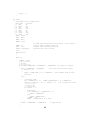
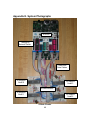
Appendix E. System Photographs.................................................................. 46
References........................................................................................................ 47
I. Introduction
1. Microcontroller-Based Systems
Microcontrollers are highly integrated, low-cost, programmable computers that
are used to design embedded systems. A typical microcontroller comprises a
central processing unit (CPU), random access memory (RAM), and input/output
(I/O) interfaces in a single package. Additional features such as on-chip analogto-digital converters (ADC), timers, and low power consumption make them
adaptable enough to be applied to a wide variety of applications. The benefit of
such tight integration is a small footprint as compared to a more general
processor that would require several additional modules and greater wiring
complexity to perform the same function.
The small footprint, low cost, and high flexibility of microcontrollers make them
ideal for integration in everything from automobiles to household appliances.
These benefits, however, come at a cost. In order to maintain low power
consumption, clock speeds are typically on the order of tens of MHz. Unlike
general-purpose computers, most have firmware to store static programs in place
of RAM for dynamic loadable programs. Thus, the microcontroller must be
reprogrammed to run new software. Modifiable data, such as variables, must be
stored in volatile memory so on-chip RAM may be present. In order to maintain
the cost-effectiveness of the chip, RAM is typically only a few kilobytes in size
and the data path may be only 8 or 16 bits wide.
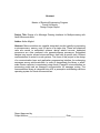
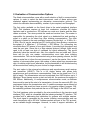
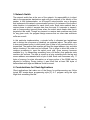
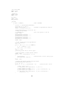
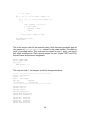
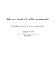
Harvard Architecture
von Neumann Architecture
Instruction Memory
CPU
CPU
Data Memory
Unified Memory
Figure 1. Harvard and von Neumann architectures
The disjoint program and data memories in a typical microcontroller imply a
Harvard architecture, as opposed to a von Neumann architecture [5]. In the von
Neumann model, instructions and data are stored in a unified memory. Memory
bandwidth is divided among program and data accesses since they share the
same bus. The design complexity is reduced, however, since memory is not
specialized. A Harvard architecture, on the other hand, has separate buses to
5
each memory, which can improve performance. Most general-purpose
computers have a Harvard on-chip L1 cache memory and a von Neumann main
memory. As will become clear, the choice of architecture will have implications
for the type of multiprocessing model that can be implemented.
2. Multiprocessor Systems
The simplest definition of a multiprocessor system is a computer that has more
than one CPU. However, this belies the breadth of technologies and
configurations that consist of multiple CPUs. At the highest level of integration,
multiple CPU cores can be placed on a single silicon die to allow chip
multiprocessing (CMP). Identical CPUs may also be packaged separately but
share a common memory interface in symmetric multiprocessing (SMP)
computers. CPUs need not be identical, as in the case of asymmetric
multiprocessing.
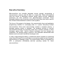
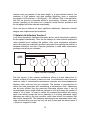
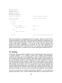
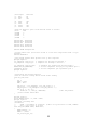
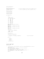
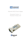
P
P
UMA
P
M
Figure 2. UMA Architecture
P
M
M
P
M
P
NUMA
Figure 3. NUMA Architecture
P
M
M
P
P
M
Cluster
Figure 4. Cluster Architecture
Memory may be shared equally among all processors, resulting in a uniform
memory access (UMA) machine or it may be divided among the processors in
non-uniform memory access (NUMA) machines. At the other end of the
spectrum, clusters combine several individual computers with a high-speed
network to give the illusion of a single computer with many processors. Grid
6
computers are even more loosely coupled than clusters and may have highlatency, low bandwidth interconnect. Clusters and grids have become popular
because they can be constructed from low-cost off-the-shelf computers and local
area networks, thus making affordable supercomputers possible.
Clusters and other tightly integrated multiprocessor systems evolved from the
same concept but are dissimilar in many ways. One of the key differences
between clusters and specially designed multiprocessor systems, such as CMP
and SMP computers, is that clusters run an operating system on each node while
CMP and SMP computers typically run a single multiprocessor-aware operating
system. Also, many small-scale CMP and SMP computers are UMA machines
but clusters resemble loosely coupled NUMA machines with longer latency
interconnect. NUMA architectures are more commonly seen in large
multiprocessor systems in which a shared memory bus becomes a bottleneck.
As in clusters, each processing node has its own memory, but there are usually
hardware mechanisms to transfer shared data between processors. Clusters lack
this hardware sharing ability and unless a unified memory is emulated in
software, each node in a cluster maintains its own memory address space. The
implications of this are twofold. First, distributed-memory machines exhibit high
performance when a task is divided so that each processor can fit its working set
into the local subset of main memory. Shared-memory machines do not suffer
from this since all main memory accesses are equal. However, since distributedmemory machines do not need to share the bus when working with local
memory, the potential performance improvement over SMP systems is
proportional to the number of separate memories. Second, without a shared
memory address space, nodes in a cluster must use interconnect to explicitly
send and receive messages instead of reading and writing a shared variable.
This message-passing latency can be relatively long compared to the
communication latency in tightly integrated systems. Thus it is important to
optimize both hardware communication efficiency and software communication
overhead. [6]
3. Communication Networks
The design of the cluster interconnect is central to performance. The parameters
of the network include shared vs. dedicated medium, bidirectional vs.
unidirectional links, synchronous vs. asynchronous transmission, link width, and
choice of topology. Each parameter must be selected depending on the
application requirements and cost limitations.
7
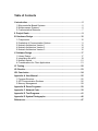
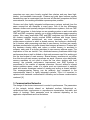
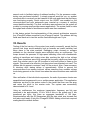
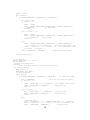
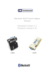
Figure 5. OSI Model
In accordance with the OSI seven-layer model, the physical layer of the network
definition specifies how many wires carry signals between nodes [6].
Communication links that transmit data serially typically have fewer wires than
those that transmit data in parallel mode, and thus are easier and cheaper to
implement. The data wires may be bidirectional, or full duplex, meaning that the
same wire switches directions to transmit and receive, or unidirectional each
wires carrying data in one direction only. Unidirectional links require twice as
many wires to transmit in both directions but offer twice the bandwidth of
bidirectional links. Additionally, the medium may be shared among several nodes
rather than just having nodes at each end. In this case, nodes attempting to
transmit may suffer a collision and the data will be garbled. Thus, some sort of
arbitration must be built in to the network. This can be accomplished by using an
arbiter that receives requests and grants permission to send, passing a token
from node to node, or collision detection with backoff and retry. As the number of
nodes on a shared bus grows, collisions become more frequent and throughput
decreases. Dedicated lines are more costly in terms of hardware but do not
exhibit such performance degradation. Data can be transmitted in different ways
over the link. Synchronous protocols require that nodes on the same link have
clocks running at the same frequency. The clock signal may be sent on a
dedicated wire or embedded in the data transmission, in which case a clock
8
recovery mechanism must be employed. Asynchronous protocols allow nodes on
the same link to transmit data without the need for clocks.
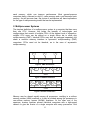
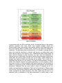
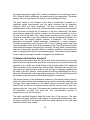
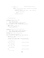
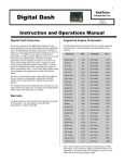
Figure 6. Network Topologies
The network topology defines the subsets of nodes that are connected by
common links. Topologies can range from a simple line to a fully connected
graph. The choice of topology determines the latency in number of hops from
one node to another and the cost of the network in number of links. For a
network in which each of N nodes can communicate with each other node, a ring
with unidirectional links has the lowest cost (N links) and a fully connected
network with bidirectional links has the lowest latency (1 hop between any two
nodes). Other designs provide a tradeoff between low latency and low cost. Tree
networks reflect the structure of many divide-and-conquer algorithms while hub
and spoke, or star, networks embody master-worker algorithms. [5]
At the data link layer, the network must provide a physical addressing scheme to
distinguish between nodes and fixed size frames of data. Addresses can be
hard-coded in each node at this level. Additional logical address can be assigned
at the network layer, which is responsible for allowing variable length messages
to be communicated. The client application should be able to make use of the
network to send and receive such messages via an abstraction known as the
application programming interface (API).
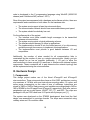
II. Project Goals
The purpose of the design project is to develop an API and hardware
communication layer for message passing with microcontrollers. The hardware
consists of the Atmel ATmega32 and ATmega16 microcontrollers. An STK500
development board is used as the main development and test platform. Program
9
code is developed in the C programming language using WinAVR (20060125
release) and CodeVisionAVR (version 1.24.7f).
Since this project encompasses both a hardware and software solution, there are
requirements and constraints on both sides. On the hardware side:
§
§
§
The system must support at least two microcontrollers.
The communication network should have reasonable latency and speed.
The system should be relatively low cost.
For the software side of the project:
§ The interface must allow variable length messages to be transmitted
between microcontrollers.
§ The system must provide a logical addressing scheme.
§ The interface should be easy to utilize in applications.
§ The implementation should fit into the limited amount of on-chip memory
and allow enough free memory to implement client applications.
§ The implementation must provide a good balance between I/O and
computation.
Additionally, the number of wires needed for all communication links is
constrained by the number of pins on a single microcontroller. Ideally, port pin
usage should be as low as possible (preferably, 1 I/O port) to allow the
microcontrollers to have enough I/O resources to interface with external system
components. These constraints will in part determine the network topology that
will be implemented using the microcontrollers.
III. Hardware Design
1. Components
This design project makes use of the Atmel ATmega32 and ATmega16
microcontrollers. These microcontrollers have an 8-bit RISC architecture running
at a maximum of 16 MHz, with most instructions executing within 1-2 cycles, and
active power consumption on the order of tens of milliamps. Instructions are
stored in 32KB or 16KB of flash memory and variables are manipulated in 2KB or
1KB of SRAM for the ATmega32 and ATmega16, respectively. Both offer various
peripherals such as on-chip timers, USART, SPI, I2C, and ADC. The chips are
packaged in 40-pin PDIPs and have 4 I/O ports with 8 pins per port. [1]
The system was developed on the STK500 development board and the final
design was assembled on prototype boards. The chips were connected using
ordinary wires and 10-conductor cable.
10
2. Evaluation of Communication Options
The Atmel microcontrollers come with a small selection of built in communication
options. In order to select the best interconnect, each of these options was
evaluated against implementing an alternative communication protocol. The
criteria for evaluation were scalability, number of pins required, and throughput.
The first option available on the Atmel chips is the serial peripheral interface
(SPI). This interface requires at least four conductors, provides full duplex
operation and is synchronous. SPI defines one node as a master and the other
nodes as slaves. Two wires provide the send and receive lines. The master is
responsible for generating the clock signal on a dedicated line and sending a
signal to a slave on its select line, thus initiating communication. The clock
frequency is limited to the main oscillator frequency divided by 4, or 16 MHz / 4 =
4 MHz. One bit can be sampled per SPI clock period, thus allowing a maximum
throughput of 4 Mbits/sec / (8 bits/byte) = 500 KB/sec. For connecting two
microcontrollers, SPI seems to be a good choice. It provides high throughput and
uses few port pins. Since this is a byte-oriented protocol, though, there would
need to be at least one byte of overhead for logical addressing. This would
effectively halve the transfer rate. Also, the scheme does not scale well. Since
there can be only one master, microcontrollers must take turns initiating
communication. This can be implemented using a token passing scheme, but this
adds an extra line to inform the next processor it can be the master. Also, as the
number of microcontrollers grows, the number of slave select lines increases per
chip. An arbiter might be an alternative, but the bandwidth is still divided among
all microcontrollers, making it a poor choice for large networks.
The next option is the universal synchronous and asynchronous serial receiver
and transmitter (USART). This is a full duplex device with allows both
asynchronous and synchronous communication. Data can be sized from 5 to 9
bits in length. The transmission rate can be adjusted from 2400 bits/sec up to 2
Mbits/sec. Since frames require a start and stop bit, the maximum throughput is
200 KB/sec. Additionally, in multiprocessor communication mode, an address
frame must be sent at the start of a transmission. As was the case with SPI, this
requirement halves the transmission rate. If variable messages were allowed at
the link layer, this would not have as much of a negative impact, however. Still,
the scalability problems that preclude the use of SPI apply to the USART as well.
The final hardware option provided by the microcontrollers is the two-wire serial
interface (TWI), which is compatible with the industry standard I2C interface. TWI
provides built in addressing and arbitration for systems with multiple masters.
The clock signal is generated by the master initiating communication and can
reach frequencies up to 400 kHz. Address packets are part of the TWI protocol,
as are variable length messages. However, in order to support arbitration, all
11
masters must use packets of the same length. In a byte-oriented network, the
overhead of 9-bit address and data packets effectively gives a maximum
throughput of 400 kbits/sec / (18 bits/byte) = 22.2 KB/sec. Due to the arbitration
built into the protocol, a separate arbiter is unnecessary. However, with many
masters operating on the same bus, contention would become prohibitive and
the throughput would be reduced considerably.
Since the above methods all have significant drawbacks, alternative network
designs were implemented and evaluated.
3. Network Architecture Version 1
In all three shared-bus interfaces discussed above, serial transmission reduces
the throughput considerably. Thus, the first attempt at a new network architecture
uses a parallel bus to address this problem. Also, since cooperative arbitration
can be slow and may indefinitely prevent a processor from gaining the medium, a
hardware arbitration unit with a fairness guarantee is used when transmission
privileges over a link are contested.
ARB
P
P
P
P
Figure 7. Version 1 Topology
The first version of the network architecture utilizes a 4-wire shared bus to
transfer a nibble (4-bit chunk) of data at a time. Four additional control wires are
used per node to communicate transmission requests and acknowledgements
between each node and the bus controller. The protocol is asynchronous to
reduce the load associated with maintaining a transmission clock. Addressing
can be more efficient than the previously discussed scheme since it can be
accomplished using a single nibble as opposed to a full byte when the number of
nodes is 16 or fewer. In order to reduce the overhead associated with having
each node actively snoop the bus to determine if it is being addressed, target
addresses are read by the bus controller, which then informs the recipient that
data will be transmitted. The hardware requirements are reasonable since each
node microcontroller must give up only one port (8 pins) and the arbiter needs 4
+ 4N pins to support N nodes.
12
The pins on each node were mapped as follows:
Pin Signal
Direction
7 BTx
IN
6 BAck
IN
5 PTx
OUT
4 Pack
OUT
3 Data3
INOUT
2 Data2
INOUT
1 Data1
INOUT
0 Data0
INOUT
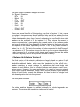
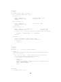
The state transition diagrams for the protocol are:
Figure 8. State Diagrams for Transmit and Receive
In order to send a byte of data, the processor toggles its PTx line and waits for an
acknowledgement from the arbiter. Once it receives the acknowledgement, it
drives the address onto the bus. This nibble is read by the arbiter, which then
selects the target node to receive requests and acknowledgements. The arbiter
will toggle BAck at the end of each state to signal a change to the next state and
13
the transmitting node toggles PTx, which is forwarded to the receiving node as
BTx. When all data is transferred, the nodes return to the ready state. The arbiter
ensures that only one request for the bus is acknowledged at a time.
The main benefit to this scheme is that data is transferred in parallel so a
significant speed improvement over the serial schemes can be expected.
However, there are some drawbacks. The bus is bidirectional, which, in
implementation, comes at the cost of extra processor cycles since an instruction
must be issued to change the I/O direction of the pins. Additionally, the arbiter
must time bus ownership carefully to ensure no two microcontrollers try to drive
the bus lines at the same time, which means introducing extra delays. It was
found that even with round robin arbitration and the increased bandwidth of a
parallel bus, the shared medium remains a bottleneck. The problem is
particularly pronounced, though seemingly unnecessary, in many scenarios.
Consider an application with 4 nodes, A, B, C, and D, sharing a bus. Data flows
primarily between nodes A and B and between nodes C and D with less frequent
communication between other pairings. Intuitively, the high traffic communication
paths are independent, but since the bus is shared, contention slows down both
paths to approximately half the expected throughput. This communication pattern
occurs frequently enough to warrant a change to the architecture.
4. Network Architecture Version 2
Using the lessons learned from the first version, a few observations can be made
about a protocol that would be optimal for connecting many microcontrollers that
generate a lot of traffic on a small subset of the possible paths. First, dedicated
links are preferred over a shared bus. Unfortunately, dedicated links require more
port pins so a tradeoff must be made in both the type of topology employed and
the width of the link. Second, communication should be unidirectional per link to
allow the full bandwidth to be used without contention. This will effectively double
the number of pins per link but will keep throughput at a maximum.
The second version of the architecture is based on the network switch model in
which all nodes interface with a central microcontroller, essentially creating a star
topology. Each node attaches to the switch using two transmit lines and two
receive lines as well as two transmit control and two receive control lines, thus
staying within the 1-port goal. This implies two unidirectional links per node with
full bandwidth on each 2-bit wide link. The communication protocol is
asynchronous as in the first version.
The state transition diagrams detail the basic flow of the protocol. The state
machines are highly symmetric with respect to receiving and transmitting. Also,
the state machines for the network switch are nearly identical to the node state
machines and are thus omitted.
14
P
P
SW
P
P
Figure 9. Version 2 Topology
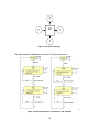
The state transition diagrams for version 2 of the protocol are:
Figure 10. State Diagrams for node Receive and Transmit
15
The pins on each node were mapped as follows:
Pin Signal Direction
7 BTx
IN
6 BAck
IN
5 PTx
OUT
4 PAck
OUT
3 Din1
IN
2 DIn0
IN
1 DOut1 OUT
0 DOut0 OUT
There are several benefits of this topology over that of version 1. First, overall
throughput is increased even though individual links are half as wide as the bus.
This is because the shared medium has been eliminated so transmitters can
initiate data transfer at any time. Second, addressing is more flexible since data
headers can be multiples of 2 bits instead of 4. This reduces the amount of
excess overhead due to zero-padding the unused portion of an address packet
sent over the wider link. One drawback of the star network is that more port pins
are required on the switch, specifically 8N vs. 4 + 4N, for any useful number of
nodes (i.e., N = 2). This limits the number of nodes connected to the ATmega16
to a maximum of 4. The number of hops for data to go from source to destination
is also increased to 2, but since control signals were mapped through the arbiter
in version 1 anyway, there is no significant increase in latency.
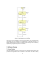
5. Network Architecture Version 3
The final version of the network architecture is largely based on version 2 with
some protocol improvements. In version 2, each node would prepend a
destination address header, which was then translated by the switch into a
header containing a source address. In applications that send single data
streams to each address, this is sufficient because each stream comes from a
unique source. However, for many applications it is useful to have the network
layer support logical addresses, or tags, which provide multiple logical reception
points on each node. Several data streams can then be sent to a single node
with disambiguation built into the protocol.
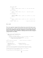
The final packet format is:
The state transition diagram is modified minimally to include tag sends and
receives. The receive state machine is similar and is omitted.
16
Figure 11. State Diagram for node Transmit
The protocol can be modified to support any fixed address, tag, and data lengths
(odd lengths are zero padded) as a characteristic of the data link layer of a
specific implementation. Support for variable length messages can be added by
implementing a higher-level protocol in software.
V. Software Design
1. Library Design
The main software component of this project is the message-passing library that
provides client applications with an interface to the network. The API is heavily
17
influenced by the widely used Message Passing Interface (MPI) standard [3,4].
Developers familiar with MPI will be able to understand the interface conventions
easily. Also, existing applications can be ported to the API with minimal effort.
At the highest level, the library provides the C API functions for initialization and
for sending and receiving messages. The first function to be called by a client
application is void net_init() which contains implementation specific
initialization as well as the default library initialization. This procedure first sets
the proper I/O pin directions and output levels.
In this design project, the library was used to extend the aOS operating system,
which was written by Anssi Ylätalo [2] and extended by Bruce Land [7]. Since the
OS is preemptive, mutual exclusion (mutex) semaphores must be used to make
the library thread-safe. Routines specific to aOS are used to initialize these
semaphores. Internal buffering is initialized next, followed by an optional
background thread, which will be explained in more detail later.
After initialization, the client application is free to utilize the high-level data
functions. The first, net_send(address, tag, length, *buffer), is used
to transmit variable length messages. This is a blocking operation, meaning that
the calling task cannot continue until all bytes are transmitted. The “address”
parameter specifies the target node according to the hardware address
assignments and “tag” specifies which tag at the target node will receive data.
The “length” parameter specifies how many units of data are transmitted from
“buffer,” which holds the message. The implementation uses the unsigned char
type for these parameters, thus allowing 255 tags on 255 addresses and
messages up to 255 bytes in length. The corresponding function to receive data
is net_recv(address, tag, length, *buffer). The “address” and “tag”
parameters correspond to the node that sent the data and the local tag that is
expected to contain the data, respectively. As in net_send(), “length” is the
maximum number of bytes to receive. Data is copied into the memory location
specified by “buffer” and the function returns a number indicating how many
bytes were actually received. A value of 255 can be specified for “address” which
will retrieve data from any address. The same applies to “tag.” This functionality
is useful for collecting data from multiple senders, tags, or both when ordering of
messages does not matter. The high-level receive function is non-blocking and
will return 0 if no data is ready.
The high-level functions described above depend on the low-level routines that
actually manipulate the signals at the physical level. These low level functions
are send_wait(Taddr, data), and receive_wait(). In order to send data,
net_send() calls send_wait() in a loop until all bytes are sent. The “Taddr”
parameter contains the tag and the address combined and “data” is the byte to
18
be sent. send_wait() is protected by a mutex which limits access to the
transmission control and data lines to one thread at a time. The function waits
until it can enter the critical section before running the network protocol state
machine described in section IV.5. The address, tag, and data are shifted out 2bits at a time from most significant bits to least significant. After transmission of a
byte is complete, the mutex lock is released. The receive_wait() function is
not called directly by net_receive(), but must be called either by another
thread or the calling thread before net_receive() can be expected to return
any data. The low-level receive function simply receives one byte of data and
buffers it internally, irrespective of address or tag. The function and the buffers
are also protected mutexes, which guarantees that competing threads will not
violate the protocol.
When data is expected in a well-defined manner, an application would only need
to call the low-level receive function enough times to ensure that all data was
received. The high-level receive would take care of sorting by tag and address.
However, in some systems, the quantity and frequency of data may not be
known. Thus, care must be taken when calling the low-level function, as it is
blocking. One solution to this problem is to use interrupts to monitor the receive
control line and provide no access to low-level receive. Another option is to use
the operating system’s multitasking ability to run a listener thread in the
background. In this implementation, using interrupts would require modifying the
core of the OS and this violates the notion of the network library as a simple addon. Thus, an optional listener is provided.
Another problem, which is also present in MPI, is that the message-passing API
does not guarantee buffering. Sends and receives will block until matching
receives and sends are performed at the other end. This can significantly reduce
performance in some cases or even lead to deadlocks. For example, consider a
scenario in which two nodes start sending data to each other at the same time.
The function calls may appear in the program code appears as follows:
Node A
Node B
1.
Send(B)
Send(A)
2.
Recv(B)
Recv(A)
Since the send functions do not return until receives are executed, both nodes
will become stuck in sending. It is up to the programmer to ensure that this
scenario does not occur, but many such situations can be resolved with good
buffering.
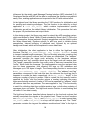
2. Integration into aOS
The aOS kernel occupies a large portion of the SRAM, which limits the stack
space available for running threads. In order to keep the network add-on
lightweight, the implementation is conservative in its memory usage. Three
19
semaphores, and four global variables are needed at a minimum. All addresses,
tags, and data arguments are unsigned bytes. The network design allows for
larger types but these limitations are reasonable for small systems. The circular
buffers that are used to sort incoming data are variable in size and add as little as
96 bytes to global memory consumption.
Figure 12. SRAM Memory Map
The preemptive multitasking abilities of aOS allow a background listener thread
to be created for the purpose of receiving data from the network and maintaining
the illusion of non-blocking receives for the task threads. The aOS thread model
runs a scheduler that will only swap a new thread in if it is put into a “runnable”
state and its priority is higher than the current thread. One approach to
successfully running the background thread is to make the listener the highest
priority thread and have it sleep so that lower priority threads have a chance to
execute. A balance between computation and I/O must be struck in order for this
to be efficient.
20
3. Network Switch
The network switch lies at the core of the network. Its responsibility is to direct
data to the appropriate destinations and notify the recipient of the identity of the
sender. In this implementation, an ATmega16 microcontroller runs a program
that implements the network communication protocol. An instance of the protocol
state machine is instantiated for each client node. Each state machine has a
receive phase in which it accepts data from the node if it requests to transmit,
and a corresponding transmit phase when the switch starts sends data that is
targeted at that node. Though any transmit or receive state machine may block
for any given node, the program design ensures that no other state machines
suffer as a result.
In this particular implementation, a circular buffer is allocated per tag/address
pair to reduce the occurrence of deadlock, as explained above. The switch uses
a store-and-forward policy in which each byte of data is fully received before it is
transmitted. The receive state machine will read the target address, tag, and data
before checking if the data can be buffered. This is done to allow the nodes to
continue processing in case the switch must stall. Once memory becomes
available (e.g., by transmitting something from a full buffer), that particular state
machine can resume. The data is stored as a byte containing both the tag and
source address concatenated with a byte of data. Each node consumes only 17
bytes of memory for state information so a large portion of the SRAM can be
devoted to buffering. During testing, it was found that at least 384 bytes of
buffered data with tags and address could be stored.
4. Considerations for Client Applications
Client applications that make use of the library for multiprocessing can follow
typical MPI master-slave programming style [3]. A C program using this style
might look something like this:
21
#include
#include
#include
#include
#include
#include
#include
#include
<mega32.h>
<stdio.h>
"aos.h"
"user_tasks.h"
"aos_core.c"
"aos_task.c"
"aos_semaphore.c"
"aos_network.c"
//network communication library
#define PID (UBYTE)0
//defines this node’s address
void task1(void)
{
net_init();
//program
{
if (PID != (UBYTE)0)
{
//worker thread code
}
else
{
//master thread code
}
}
//Nodes 1, 2, 3
//Node 0
while (1);
//loop, since threads should never return
}
Each microcontroller is programmed with this program, altering only the PID to
match the address of that node. After the network initialization is performed, the
program will diverge depending on whether the microcontroller will be the master
of the multiprocessor algorithm or one of the worker threads. Masters may
perform the same computation as workers but are also responsible for
distributing workloads and collecting results. The compiler will typically perform
dead code elimination to compile only the correct subprogram based on the PID.
VI. Testing
Individually, microcontrollers are difficult to test and debug because of the lack of
a human interface. In a complex system with multiple microcontrollers,
verification becomes even more challenging. In order to deal with this complexity,
a unit testing methodology was applied. The state machine implementations of
the communication protocols were evaluated with small programs that would
transfer predictable infinite streams of data that could be verified at the receiver
(e.g., looping over all values from 0 to 255). The circular buffers, being a generic
data structure, were tested on a PC using sequences of put and get requests that
covered both general cases and corner cases over a range of buffer lengths. The
network switch was first tested for correct reception and retransmission using just
one state machine for one node (since all are identical) against a test program.
The echo provided by the switch would indicate whether or not the data was
properly processed. Then, a state machine was added to communicate with a
22
second node to facilitate testing of address handling. For the processor nodes,
testing was performed similarly. A simple program would be run on another
microcontroller to receive from and transmit to the node and check that the library
was functioning properly. Serial output over the USART was enabled on the
microcontrollers and print statements were inserted as a means of verifying
correct dataflow internally. The final verification was performed on the system as
a whole by running simple multiprocessor applications. The system limits for data
throughput and number of simultaneous tasks were then measured.
In this design project the implementation of the network architecture supports
four ATmega32 nodes connected to an ATmega16 switch. The address and tag
fields were each set to two bits and the fixed data length was 1 byte.
VII. Results
Testing of the first version of the protocol was mostly successful, except that the
protocol test loops would randomly lock up because an invalid transition had
taken place in the state machine. Debugging output showed no software
problems so the electrical signals were analyzed using an oscilloscope. The
scope showed the presence of high-speed switching noise with characteristic
spiking at transitions and ringing noise after reaching the high or low voltage
level. Some transitions were noisy enough that incorrect values may have been
read. One solution was to use LSI inverters to build soft buffers to clean up the
signals. This proved to be effective, but the protocol was ultimately not used. The
glitches did not appear in versions 2 and 3 of the protocol. Also, it was necessary
to introduce short startup delays of approximately 100ms to prevent the
microcontrollers from reading incorrect values stemming from unstable voltage
levels being present on the control lines when the microcontrollers were switched
on.
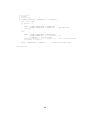
After verification of the individual components, the entire 4-processor cluster was
assembled and programmed to run a multiprocessor application. This application
distributes an array to the worker nodes in the cluster that then sum the array
and return the result to the master node. The system was successfully
demonstrated to Dr. Land.
Using an oscilloscope, the maximum transmission frequency per link was
measured to be approximately 10 kHz. With 8 links in the system and 2 bits
transferred per cycle, this gives an aggregate bandwidth of 160 kbps.
Experimentation with the OS parameters and the data stack size showed that
two tasks could easily fit into the ATmega32 SRAM. Adding a third task required
scaling back the network buffers.
23
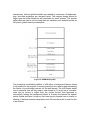
VIII. Conclusion
A network architecture and message-passing API were developed for Atmel
microcontrollers. The library was implemented on a system comprising multiple
processing nodes and a centralized switch. This system was utilized as a cluster
computer running multiprocessor applications to demonstrate the functionality of
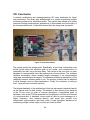
the communication layer. Verification showed that the design was successful.
Figure 13. Four Node Cluster
The system meets the design goals. Specifically, a four-node configuration was
tested, which meets the minimum goal of two nodes, and communication is
reasonably fast with only a two-hop delay. The system is low cost since no extra
hardware is required aside from the inexpensive microcontrollers. The software
interface successfully allows variable length messages to be communicated
using tags and addresses as targets. The interface provides an abstraction of the
underlying network, allowing ease of use. The memory footprint can be adjusted
to allow enough room for client applications. Finally, the constraint of using at
most 1 port per microcontroller was met.
The largest drawback to the architecture is that the star network depends heavily
on the central node for data routing. The network is also limited in size because
of the I/O pin count. In order to improve throughput, a specialized piece of
hardware, such as an FPGA programmed for this purpose, could be used instead
of a microcontroller. A hardware router might be able to route messages at a
higher frequency, thus reducing latency, and would also provide truly
independent communication with each node. A high throughput backbone for
connecting multiple routers might solve the pin-count problem.
24
Other improvements could be made as well. The data packet length could be
increased to handle longer messages with less overhead. Messages sent from a
node to itself must travel through the router in this implementation. In order to
reduce latency, local messages should be routed internally. This would also
reduce memory usage. Finally, broadcast support could be added. Some
applications would benefit from sending one command to the switch to transmit
the data to all buffers rather than having to transmit to all nodes sequentially as in
the current implementation.
Appendix A. User Manual
1. Program Structure
The network code is designed to be included in a C program targeted at an Atmel
ATmega32 microcontroller. This code compiles under CodeVisionAVR as an
extension to aOS. Minor changes consisting mainly of removing aOS dependent
code (such as semaphores) would allow use in standalone applications.
A C program written for aOS would start with the following #include directives:
#include
#include
#include
#include
#include
#include
#include
#include
<mega32.h>
<stdio.h>
"aos.h"
"user_tasks.h"
"aos_core.c"
"aos_task.c"
"aos_semaphore.c"
"aos_network.c"
//network communication library
The aos_network.c supplies the network API. The next step is to assign a
processor ID (PID) number to the node. The following line would indicate that this
processor is node zero.
#define PID (UBYTE)0
//defines this node’s address
This is followed by the first task in the program code, denoted by the task1()
function. This task is responsible for initializing the network with the void
net_init() which contains implementation specific initialization as well as the
default library initialization. This procedure first sets the proper I/O pin directions
and output levels. Semaphores are allocated for sending, receiving, and
modifying the internal buffers.
void task1(void)
{
net_init();
...
}
25
Following initialization, the program may begin to use the communication
interface. In typical MPI master-slave programs, two versions of the program
code are needed: one to be executed on the master and another for the slaves.
An effective method of writing code for master-slave programs is to include both
versions in single file and allow the compiler to select the desired version based
on the PID. In the example below, node 0 is the master and will run the program
in the ‘else’ block while all other nodes will execute the code inside of the ‘if’
block.
void task1(void)
{
net_init();
//program
{
if (PID != (UBYTE)0)
{
//worker thread code
}
else
{
//master thread code
}
}
//Nodes 1, 2, 3
//Node 0
while (1);
//loop, since threads should never return
}
Finally, since tasks should never return, an infinite loop is included as the last
line, which is the ‘while(1);’ statement above. The program can be compiled
for each node by simply modifying the PID.
2. API Communication Routines
In order to send and receive data over the network, the API provides the several
functions. Examples can be found in Appendix B.
net_send(UBYTE address, UBYTE tag, UBYTE length, UBYTE
*buffer)
This is a high-level function to transmit variable length messages. Sending
is a blocking operation, meaning that the calling task cannot continue until
all bytes are transmitted. The “address” parameter specifies the target
node according to the hardware address assignments and “tag” specifies
which tag at the target node will receive data. The “length” parameter
specifies how many units of data are transmitted from “buffer,” which holds
the message. The implementation uses the unsigned char type for these
parameters, thus allowing 255 tags on 255 addresses and messages up
to 255 bytes in length.
26
net_recv(UBYTE address, UBYTE tag, UBYTE length, UBYTE
*buffer)
This is a high-level function to The “address” and “tag” parameters
correspond to the node that sent the data and the local tag that is
expected to contain the data, respectively. The “length” parameter is the
maximum number of bytes to receive. Data is copied into the memory
location specified by “buffer” and the function returns a number indicating
how many bytes were actually received. A value of 255 can be specified
for “address” which will retrieve data from any address. The same applies
to “tag.” This functionality is useful for collecting data from multiple
senders, tags, or both when ordering of messages does not matter. The
high-level receive function is non-blocking and will return 0 if no data is
ready.
send_wait(UBYTE Taddr, UBYTE data)
In order to send data, net_send() calls send_wait() in a loop until all
bytes are sent. The “Taddr” parameter contains the tag and the address
combined and “data” is the byte to be sent. The lower 2 bits of Taddr
specify the address the next 2 bits are the tag. send_wait() is protected
by a mutex which limits access to the transmission control and data lines
to one thread at a time. The function waits until it can enter the critical
section before running the network protocol state machine. The address,
tag, and data are shifted out 2-bits at a time from most significant bits to
least significant. After transmission of a byte is complete, the mutex lock is
released.
receive_wait()
The receive_wait() function is not called directly by net_receive(),
but must be called either by another thread or the calling thread before
net_receive() can be expected to return any data. The low-level
receive function simply receives one byte of data and buffers it internally,
irrespective of address or tag. The function and the buffers are also
protected mutexes, which guarantees that competing threads will not
violate the protocol.
When data is expected in a well-defined manner, an application would
only need to call the low-level receive function enough times to ensure
that all data was received. The high-level receive takes care of sorting by
tag and address. However, in some systems, the quantity and frequency
of data may not be known. Thus, care must be taken when calling the lowlevel function, as it is blocking.
An optional listener thread can be activated to call the low-level receive function.
In the global scope, following would have to be added:
27
#define AOS_NL_TASK_PRIO (AOS_FIRST_TASK_PRIO-1)
aos_tcb *nl_tcb;
/* task control block pointer for the listener thread */
UBYTE nl_data_stack[AOS_TASK_DSTK_SIZE], nl_hw_stack[AOS_TASK_HSTK_SIZE];
/* stacks for
listener thread */
void net_listener(void);
/* function prototype */
The listener could be activated in the initialization function with the aOS task
creation function:
nl_tcb = aos_task_create(net_listener, nl_hw_stack, nl_data_stack, AOS_NL_TASK_PRIO);
The task priority should be adjusted to be higher than the program tasks for
scheduling. Note that in the aOS scheduler higher priorities are represented by
lower integer values. The listener task continuously runs the state machine to
receive data. This can be as simple as calling the low-level function in an infinite
loop.
void net_listener(void)
{
while (1)
{
receive_wait();
aos_sleep(10);
}
}
//allows another task to execute
Copying the state machine code into the body of the listener task can further
optimize the listener thread. In this case, care must be taken to avoid deadlock
and ensure mutual exclusion if other threads will call the low-level function.
Proper buffering can reduce the chance of deadlock in the system but programs
should be written to avoid scenarios where deadlock may occur. In particular,
since send functions do not return until their matching receives are executed,
nodes can become stuck in the send function. It is up to the programmer to
ensure that this scenario does not occur by matching sends with receives.
3. Memory Management
The aOS kernel occupies a large portion of the SRAM, which limits the stack
space available for running threads. In order to keep the network add-on
lightweight, the implementation is conservative in its memory usage. Three
semaphores, and four global variables are needed at a minimum. All addresses,
tags, and data arguments are unsigned bytes. The network design allows for
larger types but these limitations are reasonable for small systems. The circular
buffers that are used to sort incoming data are variable in size and add as little as
96 bytes to global memory consumption. The data stack size can be decreased
in CodeVisionAVR to allow room for tasks. A data stack of approximately 100
bytes is recommended.
28
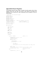
Appendix B. Demo Programs
This program sends the same array of numbers from the master node to three
workers, which sum the array. The result is sent back to the master and
displayed over the serial port. Array transmission and PID-specific code are
demonstrated.
//Cluster Demo on AOS with network support
//Sums an array
#include <mega32.h>
#include <delay.h>
#include <stdio.h>
#include "aos.h"
#include "user_tasks.h"
#include "aos_core.c"
#include "aos_task.c"
#include "aos_semaphore.c"
//omit if no semaphores or mail used
//#include "aos_mbox.c"
//omit if no mailboxes
//#include "aos_uart.c"
//omit if you don't need UART
#include "aos_network.c"
#define PID (UBYTE)0
void task1(void)
{
//For status LEDs
PORTA = 0xff;
DDRA = 0xff;
//USART Init
UCSRB = 0x18;
UBRRL = 103;
net_init();
PORTA = 0x00;
delay_ms(100);
//program
{
if (PID != (UBYTE)0)
//Nodes 1, 2, 3
{
unsigned char i = 0, sum = 0, ret;
unsigned char buf[1];
putsf("Receiving\r");
while (i < 16)
{
receive_wait();
ret = net_recv(0, 0, 1, buf);
if (ret != 0)
{
i += ret;
sum += buf[0];
printf("bytes rx: %d, Got %d, sum now %d\r\n", ret, buf[0], sum);
}
}
buf[0] = sum;
printf("Sending result %d to addr %d tag %d\r", buf[0], 0, PID);
net_send(0, PID, 1, buf);
//Tag specified by PID
}
else
//Node 0
{
unsigned char i, j, stop = 0;
29
unsigned char buf[] = {0,1,2,3,4,5,6,7,8,9,10,11,12,13,14,15}, ret;
PORTA = 0xff;
putsf("Sending data\r");
for (i = 0; i < 16; i++)
printf("%d ", buf[i]);
putsf("\r");
net_send(1, 0, 16, buf);
net_send(2, 0, 16, buf);
net_send(3, 0, 16, buf);
PORTA = 0x0f;
receive_wait();
putsf("Got first result\r");
receive_wait();
putsf("Got second result\r");
receive_wait();
putsf("Got third result\r");
PORTA = 0xf0;
while(stop < 3)
//loop on non-blocking receive
{
ret = net_recv(1, 1, 1, buf);
stop += ret;
ret = net_recv(2, 2, 1, buf+1);
stop += ret;
ret = net_recv(3, 3, 1, buf+2);
stop += ret;
}
PORTA = ~(buf[0]);
printf("Result 1=%d\r\n", buf[0]);
printf("Result 2=%d\r\n", buf[1]);
printf("Result 3=%d\r\n", buf[2]);
}
}
while (1)
{
}
}
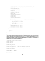
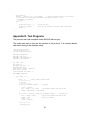
This program demonstrated transmission of large data types over a byte-oriented
network and static load balancing using the PID. A partial approximation to pi is
computed in parallel in each node and aggregated in the master. This program is
based on an MPI version provided at [3].
//Cluster Demo on AOS with network support
//Approximates Pi
#include <mega32.h>
#include <delay.h>
#include <stdio.h>
#include "aos.h"
#include "user_tasks.h"
#include "aos_core.c"
#include "aos_task.c"
#include "aos_semaphore.c"
//omit if no semaphores or mail used
//#include "aos_mbox.c"
//omit if no mailboxes
//#include "aos_uart.c"
//omit if you don't need UART
#include "aos_network.c"
#define PID
#define NUMPROCS
(UBYTE)0
(UBYTE)4
void task1(void)
{
30
//For status LEDs
PORTA = 0xff;
DDRA = 0xff;
//USART Init
UCSRB = 0x18;
UBRRL = 103;
net_init();
PORTA = 0x00;
delay_ms(100);
//program
{
if (PID == (UBYTE)0)
//Node 0 (MASTER)
{
float PI = 3.141592653589793238462643;
float mypi, pi, h, sum, x;
int n = 20, i, j, k;
//n=number of approximation intervals
UBYTE *c, buf[sizeof(float)*3];
printf("Approximation to Pi=%f\r\n", PI);
//send n to all workers
c = (UBYTE*)(&n);
//get a byte pointer to the int
PORTA = 0xff;
putsf("Sending to P1\r");
net_send(1, 0, sizeof(int), c);
putsf("Sending to P2\r");
net_send(2, 0, sizeof(int), c);
putsf("Sending to P3\r");
net_send(3, 0, sizeof(int), c);
PORTA = 0x0f;
//do the partial sum to the approximation
h = 1.0 / (float)n;
sum = 0.0;
for (i = PID + 1; i <= n; i += NUMPROCS)
{
x = h * ((double)i - 0.5);
sum += (4.0 / (1.0 + x*x));
}
mypi = h * sum;
printf("my partial sum is %f\r\n", mypi);
//wait for workers to submit partial results
PORTA = 0xf0;
for (i = 0; i < sizeof(float) * 3; i++)
{
receive_wait();
//should receive 3 floats, byte by byte
putsf("Received a byte\r");
}
PORTA = 0xaa;
//retrieve the partial results from the buffers
putsf("Pulling from buffers\r");
i = j = k = 0;
while ((i + j + k) != (sizeof(float) * 3))
//should receive 3 floats
{
//addr 1 starts at buf
i += net_recv(1, 255, sizeof(float) - i, buf + i);
//addr 2 offset by 1 float
j += net_recv(2, 255, sizeof(float) - j, buf + sizeof(float) + j);
//addr 3 offset by 2 floats
k += net_recv(3, 255, sizeof(float) - k, buf + sizeof(float) +
sizeof(float) + k);
}
31
//sum up results
pi = mypi + *((float*)buf) + *((float*)(buf + sizeof(float))) +
*((float*)(buf + sizeof(float) + sizeof(float)));
printf("pi is approximately %f, Error is %f\r\n", pi, pi - PI);
} //end PID 0
else
//Nodes 1-3 (WORKERS)
{
float mypi, h, sum, x;
int n, i;
UBYTE *c;
putsf("Waiting for n\r");
//receive n value from master
for (i = 0; i < sizeof(int); i++)
{
receive_wait();
putsf("Got a byte\r");
}
//should receive 1 int, byte by byte
i = 0;
c = (UBYTE *)(&n);
//byte pointer to the int
putsf("Pulling from buffer\r");
while (i != sizeof(int))
//retrieve n from the receive buffer
i += net_recv(0, 255, sizeof(int) - i, c);
//do the partial sum approximation
h = 1.0 / (float)n;
sum = 0.0;
for (i = PID + 1; i <= n; i += NUMPROCS)
{
x = h * ((double)i - 0.5);
sum += (4.0 / (1.0 + x*x));
}
mypi = h * sum;
//send the partial result
c = (UBYTE *)(&mypi);
putsf("Sending the result\r");
net_send(0, 0, sizeof(float), c);
//byte pointer to the float
}
} //end program
//done, never return
while (1)
{
}
}
Appendix C. Network Code
The aOS code may be obtained from [7].
This is the main library code contained in aos_network.c
//Network communication code
//Protocol version 3.0
//2x2-wire unidirectional buses
//tags and addresses supported
//Written by Kalim Moghul (kfm9)
#include "ringbuffer.h"
//Pinout for bus communication
32
//Pin
//7
//6
//5
//4
//3
//2
//1
//0
Signal
BTx
BAck
PTx
PAck
DIn1
DIn0
DOut1
DOut0
Direction
IN
IN
OUT
OUT
IN
IN
OUT
OUT
//PIDs are mapped to ports on the network switch as follows:
//Port
PID
//PORTA
0
//PORTB
1
//PORTC
2
//PORTD
3
#define
#define
#define
#define
#define
BTx
BAck
PTx
PAck
Dmask
0b10000000
0b01000000
0b00100000
0b00010000
0b11111100
#define UBYTE unsigned char
//receive buffer size (actual data stored is 1 less since ring buffer needs a 1 byte
sentinel)
#define RBUFSIZE 5
//this pragma ensures these globals won't go into registers
#pragma regallocaos_semaphore *sem_net_tx; /* Semaphore for writing from network */
aos_semaphore *sem_net_rx; /* Semaphore for reading to network */
aos_semaphore *sem_net_rbuf;
UBYTE rbuf[16][RBUFSIZE];
ringbuffer rb[16];
#pragma regalloc+
/* Semaphore for reading from receive buffer */
/* allocate ringbuffer storage per tag/address pair */
/* allocate ringbuffer per tag/address pair */
//Initializes the network interface
//must be called at startup before switch starts reading
void net_init(void)
{
int i;
PORTC = 0x00;
DDRC = 0x33;
sem_net_tx = (aos_semaphore *)aos_sem_create( 1 );
sem_net_rx = (aos_semaphore *)aos_sem_create( 1 );
sem_net_rbuf = (aos_semaphore *)aos_sem_create( 1 );
for (i=0; i < 16; i++)
rbinit(rb + i, rbuf[i], RBUFSIZE);
//start listener thread here
}
#pragma regallocstatic UBYTE txstate = 0, TAck = BAck;
#pragma regalloc+
//Performs a blocking send
//Parameters
//
Taddr = tag/address of recipient
//
data = byte of data to be sent
void send_wait(UBYTE Taddr, UBYTE data)
{
UBYTE notdone = 1;
PORTA = ~(0x02);
aos_wait(sem_net_tx);
//init ring buffers
(2-bits of tag and 2-bits of addr, 0bTTAA)
33
PORTA = ~(0x03);
while (notdone)
{
if ((UBYTE)((UBYTE)PINC & (UBYTE)BAck) != (UBYTE)TAck)
{
TAck = TAck ^ BAck;
if (txstate == 0)
{
PORTA = ~(0x04);
PORTC = (UBYTE)((UBYTE)PORTC & (UBYTE)Dmask) | (UBYTE)((UBYTE)Taddr &
(UBYTE)0x3);
//put addr crumb
txstate++;
}
else if (txstate == 1)
{
PORTA = ~(0x05);
PORTC = (UBYTE)((UBYTE)PORTC & (UBYTE)Dmask) | (UBYTE)((UBYTE)(Taddr >>
2) & (UBYTE)0x3);
//put tag crumb
txstate++;
}
else
{
PORTC = (UBYTE)((UBYTE)PORTC & (UBYTE)Dmask) | (UBYTE)((UBYTE)(data >>
((5 - txstate) << 1)) & (UBYTE)0x3);
//put data crumb, MSBs go first
txstate = ((txstate >= 5) ? 0 : txstate + 1);
//do 4 iterations of data
if (txstate == 0) notdone = 0;
}
PORTC = (UBYTE)PORTC ^ (UBYTE)PTx;
//toggle the transmit signal
}
}
aos_signal(sem_net_tx);
}
#pragma regallocstatic UBYTE rxstate = 0, RAck = 0;
#pragma regalloc+
//Performs a blocking recieve
//Modifies
//
global rb[(tag<<2)|addr] will contain the received data
void receive_wait(void)
{
UBYTE notdone = 1;
UBYTE Raddr, Rtag, Rdata;
aos_wait(sem_net_rx);
while (notdone)
{
if ((UBYTE)((UBYTE)PINC & (UBYTE)BTx) != (UBYTE)RAck)
//if signal was toggled
{
RAck = (UBYTE)RAck ^
//store the last Ack state (toggle)
if (rxstate == 0)
{
Raddr = (UBYTE)(PINC >> 2) & (UBYTE)0x3; //read address crumb (2-bits)
PORTC = (UBYTE)PORTC ^ (UBYTE)PAck;
//toggle the Ack
rxstate++;
}
else if (rxstate == 1)
{
Rtag = (UBYTE)(PINC >> 2) & (UBYTE)0x3;
//read tag crumb
PORTC = (UBYTE)PORTC ^ (UBYTE)PAck;
//toggle the Ack
rxstate++;
}
else
{
//read data crumb
Rdata = (UBYTE)(Rdata << 2) | (UBYTE)((UBYTE)(PINC >> 2) & (UBYTE)0x3);
rxstate = ((rxstate >= 5) ? 0 : rxstate + 1); //do 4 iterations of data
PORTC = (UBYTE)PORTC ^ (UBYTE)PAck;
//toggle the Ack
34
if (rxstate == 0)
//finished receiving, store data
{
notdone = 0;
while(1) //stall here while trying to find space in the ring buffer
{
aos_wait(sem_net_rbuf);
if(rbput(rb + ((Rtag<<2)|Raddr), Rdata)) //add to ring buffer
{
aos_signal(sem_net_rbuf);
break;
}
aos_signal(sem_net_rbuf);
}
}
}
}
}
aos_signal(sem_net_rx);
}
//Performs a blocking send of a buffer
//Parameters
//
addr = address of target
//
tag = tag to receive data
//
length = number of bytes to transmit from buffer
//
buf = pointer to buffer containing message
void net_send(UBYTE addr, UBYTE tag, UBYTE length, UBYTE *buf)
{
UBYTE i, Taddr;
Taddr = (tag << 2) | (addr & 0x3);
for (i = 0; i < length; i++)
send_wait(Taddr, buf[i]);
}
//Performs a blocking receive from a specific source
//Parameters
//
addr = address of source to receive from (255=any)
//
tag = local tag to receive data from (255=any)
//
length = maximum number of bytes to receive
//Returns
//
The number of bytes actually received
//Modifies
//
buf contains the received data
UBYTE net_recv(UBYTE addr, UBYTE tag, UBYTE length, UBYTE *buf)
{
UBYTE count = 0, *temp, st, et, sa, ea, i, j;
aos_wait(sem_net_rbuf);
//determine tag and source address ranges to get data from
if ((tag == 255) && (addr == 255))
//any tag, any source
{
st = 0; et = 3;
sa = 0; ea = 3;
}
else if (tag == 255)
//any tag, one source
{
st = 0; et = 3;
sa = ea = addr;
}
else if (addr == 255)
//one tag, any source
{
st = et = tag;
sa = 0; ea = 3;
}
else
//one tag, one source
{
st = et = tag;
35
sa = ea = addr;
}
for (i = st; (i <= et) && (count < length); i++)
{
for (j = sa; (j <= ea) && (count < length); j++)
{
do
{
temp = rbget(rb + ((i<<2)|j));
if (temp != NULL)
{
buf[count] = *temp;
count++;
}
}
while ((count < length) && temp);
}
}
aos_signal(sem_net_rbuf);
return count;
}
This is the source code for the network switch. Note that each processor gets its
own version of void procN(void), where N is the node number. The code for
proc0 is provided below. This code can be copied for proc1, proc2, and proc3
with slight modifications. Each should receive its own unique PORT and PIN,
function name and procnum assignment.
#define COMPORT PORTB
#define COMPIN PINB
void proc1()
{
UBYTE procnum = 1;
...
The code for node 1, for example, would be changed as above.
/*****************************************************
Project : networkswitch
Version : 3.0
Author : Kalim Moghul
Chip type
: ATmega16
Clock frequency
: 16.000000 MHz
*****************************************************/
#include <mega16.h>
#include <delay.h>
#include <stdio.h>
#include "ringbuffer.h"
#define UBYTE unsigned char
#define UINT unsigned int
#define
#define
#define
#define
#define
BTx
BAck
PTx
PAck
Dmask
0b10000000
0b01000000
0b00100000
0b00010000
0b11110011
36
#define RBUFSIZE 24
#pragma regallocUINT rbuf[16][RBUFSIZE];
ringbuffer rb[16];
#pragma regalloc+
void
void
void
void
/* allocate ringbuffer storage per tag/address pair */
/* allocate ringbuffer per dest tag/address pair */
proc0(void);
proc1(void);
proc2(void);
proc3(void);
void main(void)
{
int i;
//PORTn Pinouts
//Pin SignalDirection
//7
BTx
OUT
//6
BAck OUT
//5
PReq IN
//4
PAck IN
//3
Data3 OUT
//2
Data2 OUT
//1
Data1 IN
//0
Data0 IN
DDRA=0xcc;//interface for node 0
PORTA=0x00;
DDRB=0xcc; //interface for node 1
PORTB=0x00;
DDRC=0xcc; //interface for node 2
PORTC=0x00;
DDRD=0xcc; //interface for node 3
PORTD=0x00;
//USART Init for debugging
//UCSRB = 0x18;
//UBRRL = 103;
delay_ms(1000);
//Initialize ring buffers
for (i = 0; i < 16; i++)
rbinit(rb + i, rbuf[i], RBUFSIZE);
//init ring buffers
while(1)
{
proc0();
proc1();
proc2();
proc3();
}//end main loop
}
#define COMPORT PORTA
#define COMPIN PINA
void proc0()
{
//this function's owner (should be const, but CodeVisionAVR doesn't allow it)
UBYTE procnum = 0;
//concatenated address and data, as stored in ringbuffer
static UINT Raddrdata, Taddrdata;
static UBYTE Raddr, Rtag, Rdata, Tdata, Taddr;
static UBYTE rxstate = 0, txstate = 6, txq = 0, txready = 0;
static UBYTE RAck = 0, TAck = PAck, rxpause = 0;
UBYTE i;
37
//**********
// receive
//**********
if (((COMPIN & PTx) != RAck) || rxpause)
{
RAck = (rxpause) ? RAck : RAck ^ PTx;
if (rxstate == 0)
{
Raddr = COMPIN & 0x3;
//read dest address crumb
COMPORT = COMPORT ^ BAck;
//toggle the Ack
rxstate++;
}
else if (rxstate == 1)
{
Rtag = COMPIN & 0x3;
//read dest tag crumb
COMPORT = COMPORT ^ BAck;
rxstate++;
}
else if (rxstate <= 5)
{
Rdata = (Rdata << 2) | (COMPIN & 0x3);
//read data crumb
COMPORT = COMPORT ^ BAck;
//toggle the Ack
if (rxstate == 5)
//last data received, so construct value for ringbuffer
{
Raddrdata = (((UINT)procnum) << 8) | (UINT)Rdata;
}
rxstate++;
}
if (rxstate == 6)
{
//try to put addr/data in queue, stall if full
rxpause = !(rbput(rb + ((Rtag<<2)|Raddr), Raddrdata));
if (!rxpause)
{
rxstate = 0;
}
}
}
//**********
// transmit
//**********
if (txstate == 6)
//if ready to transmit something
{
txready = 0;
//round robin arbitration to select from which dest tag queue to transmit
for (i = 0; i < 4; i++)
{
txq = (txq + 1) & 0x3;
//select next dest tag for this processor
//see if it has anything in queue with selected tag
if (!rbisempty(rb + ((txq<<2)|procnum)))
{
txready = 1;
txstate = 0;
Taddrdata = *(rbget(rb + ((txq<<2)|procnum))); //get addr/data value
Taddr = (UBYTE)(Taddrdata >> 8);
Tdata = (UBYTE)(Taddrdata);
break;
}
}
}
if (txready)
{
if ((COMPIN & PAck) != TAck)
{
38
TAck = TAck ^ PAck;
if (txstate == 0)
{
COMPORT = (COMPORT &
txstate++;
}
else if (txstate == 1)
{
COMPORT = (COMPORT &
txstate++;
}
else if (txstate <= 4)
{
//put data crumb
COMPORT = (COMPORT &
txstate++;
}
else
{
COMPORT = (COMPORT &
txstate = 6;
}
COMPORT = COMPORT ^ BTx;
Dmask) | (Taddr << 2); //put source addr crumb
Dmask) | (txq << 2);
//put dest tag crumb
Dmask) | ((Tdata >> (8 - (txstate << 1))) & 0xc);
Dmask) | ((Tdata << 2) & 0xc);
//put data crumb
//toggle the transmit signal
}
}
}
#undef COMPORT
#undef COMPIN
This is the ringbuffer.h header file that defines the circular buffer data structure.
This data structure is used in both the library code and the network switch code
with one minor change: the data type in the library is one byte while the switch
requires two bytes. The type definition of rbdatatype below would be changed to
‘unsigned char’ for the library.
/*
Ring (circular) buffer implementation.
Author: Kalim Moghul ([email protected])
Invariants:
head==tail iff buffer is empty.
If buffer is not empty, head points at next valid element to be consumed.
tail always points at the next empty element.
=> There is always one unused element in a full buffer.
=> length must be greater than 1
*/
typedef unsigned int rbdatatype;
typedef struct ringbuf
{
rbdatatype *buf;
unsigned char length;
unsigned char head, tail;
} ringbuffer;
//define storage type of ringbuffer
//points to data array
//length of data array
//producer and consumer indices
//initializes the given ringbuffer with the supplied array and its length
inline void rbinit(ringbuffer *rb, rbdatatype *array, unsigned char length);
//returns boolean true if the ringbuffer is empty, false otherwise
inline unsigned char rbisempty(ringbuffer *rb);
//returns boolean true if the ringbuffer is full, false otherwise
39
inline unsigned char rbisfull(ringbuffer *rb);
//consumes an element from the buffer
//returns NULL if buffer is empty or a pointer to the array element otherwise
inline rbdatatype* rbget(ringbuffer *rb);
//puts an element into the buffer
//returns 0 if buffer is full, otherwise returns 1
inline unsigned char rbput(ringbuffer *rb, rbdatatype c);
#include "ringbuffer.c"
This is the ringbuffer.c source code for the circular buffer implementation.
/*
Ring (circular) buffer implementation.
Author: Kalim Moghul ([email protected])
Invariants:
head==tail iff buffer is empty.
If buffer is not empty, head points at next valid element to be consumed.
tail always points at the next empty element.
=> There is always one unused element in a full buffer.
=> length must be greater than 1
*/
//initializes the given ringbuffer with the supplied array and its length
inline void rbinit(ringbuffer *rb, rbdatatype *array, unsigned char length)
{
rb->buf = array;
rb->length = length;
rb->head = rb->tail = 0;
}
//returns boolean true if the ringbuffer is empty, false otherwise
inline unsigned char rbisempty(ringbuffer *rb)
{
return (rb->head == rb->tail);
}
//returns boolean true if the ringbuffer is full, false otherwise
inline unsigned char rbisfull(ringbuffer *rb)
{
return (((rb->tail + 1) % rb->length) == rb->head);
}
//consumes an element from the buffer
//returns NULL if buffer is empty or a pointer to the array element otherwise
inline rbdatatype* rbget(ringbuffer *rb)
{
rbdatatype *ret;
if (rb->head == rb->tail)
return NULL;
else
{
ret = rb->buf + rb->head;
//index into the array at head pointer
//move head pointer forward one element (with wraparound)
rb->head = (rb->head + 1) % rb->length;
return ret;
}
}
//puts an element into the buffer
//returns 0 if buffer is full, otherwise returns 1
inline unsigned char rbput(ringbuffer *rb, rbdatatype c)
40
{
char newtail;
newtail = (rb->tail + 1) % rb->length;
//calculate where the new tail would be
//if the new tail would make the buffer look empty, buffer is full
if (newtail == rb->head)
return 0;
else
{
rb->buf[rb->tail] = c;
//store the data
rb->tail = newtail;
//move the tail pointer forward (with wraparound)
return 1;
}
}
Appendix D. Test Programs
The protocol test code compiles under WinAVR with avr-gcc.
This code was used to test the first version of the protocol. It is interrupt-based
and allows timing to be adjusted easily.
//Bus controller tester
//Protocol version 1.0
//4-wire bidirectional bus
#include
#include
#include
#include
<inttypes.h>
<avr/io.h>
<avr/interrupt.h>
<avr/sleep.h>
int time = 500;
int count = 0;
unsigned char data = 0;
unsigned char buf;
enum {ready, receive, display};
char state = ready;
const unsigned char addr = 1;
ISR(TIMER0_COMP_vect)
{
if (--time <= 0)
{
time = 1;
//every "time" milliseconds
//**************
// receive
//**************
if (bit_is_set(PINC, PINC7))
//got BTx
{
state = receive;
buf = (PINC << 4) & 0xf0;
//read upper nibble from data lines
PORTC = 0b00010000; //raise PAck
}
if ((state == receive) && bit_is_clear(PINC, PINC7))
//got BTx low
{
buf |= (PINC & 0x0f);
//read lower nibble from data lines
PORTC = 0x00;
//drop all signals
count = 0;
state = display;
}
//**************
// display echo
41
//**************
if (state == display)
{
PORTD = ~buf;
count++;
time = 30;
if (count == 3)
{
count = 0;
state = ready;
}
}
//**************
// transmit
//**************
if (state == ready)
{
if (count == 0)
{
PORTC = 0b00100000;
//raise PReq
data++;
//data to be sent
count++;
}
else if (count == 1)
{
if (bit_is_set(PINC, PINC6)) //got BAck
{
DDRC = 0x3f;
//set data lines as outputs
//drop PReq, raise PTx and send addr
PORTC = 0b00010000 | (addr & 0x0f);
count++;
}
}
else if (count == 2)
{
if (bit_is_clear(PINC, PINC6)) //got BAck low
{
//PORTC = 0b00000110;
//drop PTx and send data 0110
PORTC = (data >> 4) & 0x0f;
count++;
}
}
else if (count == 3)
{
if (bit_is_set(PINC, PINC6))
//got BAck
{
//PORTC = 0b00011010; //raise PTx and send data 1010
PORTC = 0b00010000 | (data & 0x0f);
count++;
}
}
else if (count == 4)
{
if (bit_is_clear(PINC, PINC6)) //got BAck low
{
DDRC = 0x30;
//set data lines as inputs
PORTC = 0x00;
//drop all signals
count = 0;
}
}
}
}
}
int main()
{
42
//using PORTC for bus communication
//Pin Signal
Direction
//7
BTx
IN
//6
BAck
IN
//5
PReq
OUT
//4
PTx/PAck OUT
//3
Data3
INOUT
//2
Data2
INOUT
//1
Data1
INOUT
//0
Data0
INOUT
PORTC = 0x00;
DDRC = 0x30;
DDRD = 0xff;
PORTD = 0xff;
TIMSK = 2;
OCR0 = 250;
TCCR0 = 0b00001011;
//(16 MHz CLK)/(64 prescaler)/(250 counter) = 1000 ticks/sec
//turn on timer 0 compare match ISR
//Compare match interrupt every 1 ms
//prescaler 64, clear on match
sei();
while (1)
{
//PORTD = ~PINC;
}
}
Version 2 of the protocol was tested with this code. Since Version 3 is a simple
extension of Version 2, no additional tester code was required. This code runs in
a while loop and allows the throughput to be measured.
//Network switch tester (fast version)
//Protocol version 2.0
//2x2-wire unidirectional buses
#include <inttypes.h>
#include <avr/io.h>
#include <avr/interrupt.h>
#define
#define
#define
#define
#define
BTx
BAck
PTx
PAck
Dmask
0b10000000
0b01000000
0b00100000
0b00010000
0b11111100
#define UCHAR unsigned char
int time = 500;
unsigned char txstate = 0, TAck = BAck;
unsigned char rxstate = 0, RAck = 0;
unsigned char data = 0;
unsigned char buf;
unsigned char Raddr;
const unsigned char Taddr = 1;
unsigned int dispcount = 0;
unsigned char wait[1] = {1};
ISR(TIMER0_COMP_vect)
{
if (--time <= 0)
{
43
wait[0] = 0;
}
}
int main()
{
//using PORTC for bus communication
//Pin Signal
Direction
//7
BTx
IN
//6
BAck
IN
//5
PTx
OUT
//4
PAck
OUT
//3
DIn1
IN
//2
DIn0
IN
//1
DOut1
OUT
//0
DOut0
OUT
PORTC = 0x00;
DDRC = 0x33;
DDRD = 0xff;
PORTD = 0xff;
TIMSK = 2;
OCR0 = 250;
TCCR0 = 0b00001011;
//(16 MHz CLK)/(64 prescaler)/(250 counter) = 1000 ticks/sec
//turn on timer 0 compare match ISR
//Compare match interrupt every 1 ms
//prescaler 64, clear on match
sei();
while(wait[0])
{
}
while (1)
{
//PORTD = ~PINC;
//**************
// receive
//**************
if ((UCHAR)((UCHAR)PINC & (UCHAR)BTx) != (UCHAR)RAck) //if signal was toggled
{
RAck = (UCHAR)RAck ^ (UCHAR)BTx;
//store the last Ack state (toggle)
if (rxstate == 0)
{
Raddr = (UCHAR)(PINC >> 2) & (UCHAR)0x3; //read address crumb (2-bits)
rxstate++;
}
else
{
//read data crumb
buf = (UCHAR)(buf << 2) | (UCHAR)((UCHAR)(PINC >> 2) & (UCHAR)0x3);
rxstate = ((rxstate >= 4) ? 0 : rxstate + 1);
//do 4 iterations of data
//**************
// display echo
//**************
if (rxstate == 0)
{
dispcount++;
/*if ((UCHAR)buf == (UCHAR)(data - 1))
PORTD = (UCHAR)0xaa;
else
PORTD = (UCHAR)0x66;*/
//PORTD = ~buf;
PORTD = ~((dispcount >> 8) & 0xff);
}
}
PORTC = (UCHAR)PORTC ^ (UCHAR)PAck;
//toggle the Ack
}
44
//**************
// transmit
//**************
if ((UCHAR)((UCHAR)PINC & (UCHAR)BAck) != (UCHAR)TAck)
{
TAck = TAck ^ BAck;
if (txstate == 0)
{
PORTC = (UCHAR)((UCHAR)PORTC & (UCHAR)Dmask)
| (UCHAR)((UCHAR)Taddr & (UCHAR)0x3);
//put addr crumb
txstate++;
}
else
{
PORTC = (UCHAR)((UCHAR)PORTC & (UCHAR)Dmask)
| (UCHAR)((UCHAR)(buf >> ((4 - txstate) << 1))
& (UCHAR)0x3);
//put data crumb
txstate = ((txstate >= 4) ? 0 : txstate + 1);
//do 4 iterations of data
if (txstate == 0) data++;
}
PORTC = (UCHAR)PORTC ^ (UCHAR)PTx;
//toggle the transmit signal
}
}//end main loop
}
45
Appendix E. System Photographs
STK500
Atmega16
Network Switch
Power and
Data Cables
ATmega32
Node 0
ATmega32
Node 3
4-Node Module
ATmega32
Node 1
ATmega32
Node 2
4-Node Cluster
46
PORTC Connections
Data
Cable
0.1uF capacitor
16 MHz crystal,
22pf capacitors
Processing Node
References
[1] Atmel ATmega32 and ATmega16 Datasheets. Rev. 2503H-03/05. Accessed
March 2006. <http://www.atmel.com/products/avr/>
[2] aOS – a RTOS for AVR. Accessed March 2006.
<http://www.tietomyrsky.fi/projektit/aos/>
[3] The Message Passing Interface (MPI) Standard. Accessed March 2006.
<http://www-unix.mcs.anl.gov/mpi>
[4] MPI-2: Extensions to the Message-Passing Interface. Accessed March 2006.
<http://www.mpi-forum.org>
[5] Hennessy, John L. and Patterson, David A. Computer Architecture: A
Quantitative Approach, 3rd ed. Morgan Kaufmann 2003.
[6] Peterson, Larry L. and Davie, Bruce S. Computer Networks: A Systems
Approach, 3rd ed. Morgan Kaufmann 2003.
[7] A preemptive multitasking, OS for Atmel Mega32 microcontrollers. Accessed
March 2006.
<http://instruct1.cit.cornell.edu/courses/ee476/RTOS/index.html>
47