1
Microimaging
Hardware
Installation
UNITY
INOVA NMR Spectrometer Systems
Pub. No. 01-999070-00, Rev. A0499
Microimaging Hardware Installation
UNITYINOVA NMR Spectrometer Systems
Pub. No. 01-999070-00, Rev. A0499
Revision history:
A0499 – Initial release
Applicability of manual:
Microimaging module installed on
UNITYINOVA NMR spectrometer systems
Technical contributors: Simon Chu, Tim Luca, Emil Johnson
Technical writers: Mike Carlisle, Daniel Steele
Technical editor: James Welch
Copyright 1999 by Varian, Inc.
3120 Hansen Way, Palo Alto, California 94304
http://www.varianinc.com
All rights reserved. Printed in the United States.
The information in this document has been carefully checked and is believed to
be entirely reliable. However, no responsibility is assumed for inaccuracies.
Statements in this document are not intended to create any warranty, expressed
or implied. Specifications and performance characteristics of the software
described in this manual may be changed at any time without notice. Varian
reserves the right to make changes in any products herein to improve reliability,
function, or design. Varian does not assume any liability arising out of the
application or use of any product or circuit described herein; neither does it
convey any license under its patent rights nor the rights of others. Inclusion in this
document does not imply that any particular feature is standard on the instrument.
UNITYINOVA, MERCURY, UNITYplus, UNITY, GEMINI 2000, Gemini, GLIDE,
VXR, XL, VNMR, VnmrS, VnmrX, VnmrI, VnmrV, VnmrSGI, MAGICAL,
AutoLock, AutoShim, AutoPhase, limNET, Ultra•nmr, Indirect•nmr, Auto•nmr,
Triple•nmr, MagicAngle•nmr, Proton•nmr, Bioproton•nmr, ASM, and SMS are
registered trademarks or trademarks of Varian, Inc. OpenWindows, Sun, Solaris,
Suninstall, SPARC, and SPARCstation are registered trademarks or trademarks
of Sun Microsystems, Inc. and SPARC Int. Oxford is a registered trademark of
Oxford Instruments LTD. Ethernet is a registered trademark of Xerox
Corporation. Other product names in this document are registered trademarks or
trademarks of their respective holders.
Table of Contents
SAFETY PRECAUTIONS ................................................................................... 5
INOVA Microimaging Module ...................................................................... 9
UNITY
Preparing for Installation ................................................................................ 10
Installing Microimaging Hardware ................................................................. 12
Installing the Imaging Switch Board .............................................................................
Installing the PTS Synthesizer with Overrange ............................................................
Installing the Connector, DECC, and SDAC Boards ....................................................
Installing the Gradient Waveform Generator Boards ...................................................
Installing the Voltage Regulator Module ......................................................................
Connecting the Cables ...................................................................................................
Finishing the Hardware Installation ..............................................................................
Testing the DECC Accessory ........................................................................................
Connecting the Power ...................................................................................................
Installing the Junction Unit and Gradient Harness ........................................................
Installing the Air Cooling System .................................................................................
Installing the Preamplifier Attenuator ...........................................................................
Installing Gradient Coils and the Microimaging Probe ................................................
12
14
14
15
17
17
18
18
19
19
20
21
21
Configuring VNMR for Microimaging ............................................................ 21
Testing and Verifying the Gradient System .................................................. 22
Testing Gradient Controls ............................................................................................. 22
Testing the Gradient Compensation System ................................................................. 22
Calibrating and Configuring Gradient Strength ........................................... 23
Creating the RF Pulse Calibration File .........................................................................
Calibrating Gradient Strengths ......................................................................................
Creating the Gradient Table ..........................................................................................
Calibrating Gradient Strengths (ecctool) .......................................................................
Creating the RF Pulse Calibration File .........................................................................
Creating the Gradient Table ..........................................................................................
23
23
24
25
25
26
System Protection and Status ....................................................................... 27
Index ................................................................................................................. 31
01-999070-00 A0499
UNITYINOVA
Microimaging Hardware Installation
3
List of Figures
Figure 1. Microimaging System Layout ................................................................................... 9
Figure 2. Microimaging Cabinet with Gradient Control System, Open Front View .............. 10
Figure 3. RF Control Cardcage, Front View, Showing Slot Assignments .............................. 14
Figure 4. UNITYINOVA Microimaging Interconnect ............................................................... 16
Figure 5. Voltage Regulator Module Installation .................................................................... 17
Figure 6. Self-Test Jumper on DECC Board .......................................................................... 18
Figure 7. Air Flow Diagram ................................................................................................... 20
Figure 8. Gradient Interlocks and Status Display ................................................................... 27
Figure 9. Gradient Amplifier, Front View (top), Back View (bottom) ................................... 28
Figure 10. Gradient Junction Unit, Top View ......................................................................... 29
List of Tables
Table 1. Gradient Waveform Generator Board Jumper Settings ............................................
Table 2. Microimaging Cabinet Power Connections ..............................................................
Table 3. Typical Microimaging Software Configuration File .................................................
Table 4. Amplifier Faults ........................................................................................................
Table 5. Gradient System Faults .............................................................................................
4
UNITYINOVA
Microimaging Hardware Installation
01-999070-00 A0499
15
19
21
28
29
SAFETY PRECAUTIONS
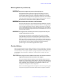
The following warning and caution notices illustrate the style used in Varian manuals for
safety precaution notices and explain when each type is used:
WARNING: Warnings are used when failure to observe instructions or precautions
could result in injury or death to humans or animals, or significant
property damage.
CAUTION:
Cautions are used when failure to observe instructions could result in
serious damage to equipment or loss of data.
Warning Notices
Observe the following precautions during installation, operation, maintenance, and repair
of the instrument. Failure to comply with these warnings, or with specific warnings
elsewhere in Varian manuals, violates safety standards of design, manufacture, and
intended use of the instrument. Varian assumes no liability for customer failure to comply
with these precautions.
WARNING: Persons with implanted or attached medical devices such as
pacemakers and prosthetic parts must remain outside the 5-gauss
perimeter from the centerline of the magnet.
The superconducting magnet system generates strong magnetic fields that can
affect operation of some cardiac pacemakers or harm implanted or attached
devices such as prosthetic parts and metal blood vessel clips and clamps.
Pacemaker wearers should consult the user manual provided by the pacemaker
manufacturer or contact the pacemaker manufacturer to determine the effect on
a specific pacemaker. Pacemaker wearers should also always notify their
physician and discuss the health risks of being in proximity to magnetic fields.
Wearers of metal prosthetics and implants should contact their physician to
determine if a danger exists.
Refer to the manuals supplied with the magnet for the size of a typical 5-gauss
stray field. This gauss level should be checked after the magnet is installed.
WARNING: Keep metal objects outside the 10-gauss perimeter from the centerline
of the magnet.
The strong magnetic field surrounding the magnet attracts objects containing
steel, iron, or other ferromagnetic materials, which includes most ordinary
tools, electronic equipment, compressed gas cylinders, steel chairs, and steel
carts. Unless restrained, such objects can suddenly fly towards the magnet,
causing possible personal injury and extensive damage to the probe, dewar, and
superconducting solenoid. The greater the mass of the object, the more the
magnet attracts the object.
Only nonferromagnetic materials—plastics, aluminum, wood, nonmagnetic
stainless steel, etc.—should be used in the area around the magnet. If an object
is stuck to the magnet surface and cannot easily be removed by hand, contact
Varian service for assistance.
01-999070-00 A0499
UNITYINOVA
Microimaging Hardware Installation
5
SAFETY PRECAUTIONS
Warning Notices (continued)
Refer to the manuals supplied with the magnet for the size of a typical 10-gauss
stray field. This gauss level should be checked after the magnet is installed.
WARNING: Only qualified maintenance personnel shall remove equipment covers
or make internal adjustments.
Dangerous high voltages that can kill or injure exist inside the instrument.
Before working inside a cabinet, turn off the main system power switch located
on the back of the console.
WARNING: Do not substitute parts or modify the instrument.
Any unauthorized modification could injure personnel or damage equipment
and potentially terminate the warranty agreements and/or service contract.
Written authorization approved by a Varian, Inc. product manager is required
to implement any changes to the hardware of a Varian NMR spectrometer.
Maintain safety features by referring system service to a Varian service office.
WARNING: Do not operate in the presence of flammable gases or fumes.
Operation with flammable gases or fumes present creates the risk of injury or
death from toxic fumes, explosion, or fire.
WARNING: Leave area immediately in the event of a magnet quench.
If the magnet dewar should quench (sudden appearance of gasses from the top
of the dewar), leave the area immediately. Sudden release of helium or nitrogen
gases can rapidly displace oxygen in an enclosed space creating a possibility of
asphyxiation. Do not return until the oxygen level returns to normal.
WARNING: Avoid helium or nitrogen contact with any part of the body.
In contact with the body, helium and nitrogen can cause an injury similar to a
burn. Never place your head over the helium and nitrogen exit tubes on top of
the magnet. If helium or nitrogen contacts the body, seek immediate medical
attention, especially if the skin is blistered or the eyes are affected.
WARNING: Do not look down the upper barrel.
Unless the probe is removed from the magnet, never look down the upper
barrel. You could be injured by the sample tube as it ejects pneumatically from
the probe.
WARNING: Do not exceed the boiling or freezing point of a sample during variable
temperature experiments.
A sample tube subjected to a change in temperature can build up excessive
pressure, which can break the sample tube glass and cause injury by flying glass
and toxic materials. To avoid this hazard, establish the freezing and boiling
point of a sample before doing a variable temperature experiment.
6
UNITYINOVA
Microimaging Hardware Installation
01-999070-00 A0499
SAFETY PRECAUTIONS
Warning Notices (continued)
WARNING: Support the magnet and prevent it from tipping over.
The magnet dewar has a high center of gravity and could tip over in an
earthquake or after being struck by a large object, injuring personnel and
causing sudden, dangerous release of nitrogen and helium gasses from the
dewar. Therefore, the magnet must be supported by at least one of two methods:
with ropes suspended from the ceiling or with the antivibration legs bolted to
the floor. Refer to the Installation Planning Manual for details.
WARNING: Do not remove the relief valves on the vent tubes.
The relief valves prevent air from entering the nitrogen and helium vent tubes.
Air that enters the magnet contains moisture that can freeze, causing blockage
of the vent tubes and possibly extensive damage to the magnet. It could also
cause a sudden dangerous release of nitrogen and helium gases from the dewar.
Except when transferring nitrogen or helium, be certain that the relief valves are
secured on the vent tubes.
WARNING: On magnets with removable quench tubes, keep the tubes in place
except during helium servicing.
On Varian 200- and 300-MHz 54-mm magnets only, the dewar includes
removable helium vent tubes. If the magnet dewar should quench (sudden
appearance of gases from the top of the dewar) and the vent tubes are not in
place, the helium gas would be partially vented sideways, possibly injuring the
skin and eyes of personnel beside the magnet. During helium servicing, when
the tubes must be removed, follow carefully the instructions and safety
precautions given in the manual supplied with the magnet.
Caution Notices
Observe the following precautions during installation, operation, maintenance, and repair
of the instrument. Failure to comply with these cautions, or with specific cautions elsewhere
in Varian manuals, violates safety standards of design, manufacture, and intended use of
the instrument. Varian assumes no liability for customer failure to comply with these
precautions.
CAUTION:
Keep magnetic media, ATM and credit cards, and watches outside the
5-gauss perimeter from the centerline of the magnet.
The strong magnetic field surrounding a superconducting magnet can erase
magnetic media such as floppy disks and tapes. The field can also damage the
strip of magnetic media found on credit cards, automatic teller machine (ATM)
cards, and similar plastic cards. Many wrist and pocket watches are also
susceptible to damage from intense magnetism.
Refer to the manuals supplied with the magnet for the size of a typical 5-gauss
stray field. This gauss level should be checked after the magnet is installed.
01-999070-00 A0499
UNITYINOVA
Microimaging Hardware Installation
7
SAFETY PRECAUTIONS
Caution Notices (continued)
CAUTION:
Check helium and nitrogen gas flowmeters daily.
Record the readings to establish the operating level. The readings will vary
somewhat because of changes in barometric pressure from weather fronts. If
the readings for either gas should change abruptly, contact qualified
maintenance personnel. Failure to correct the cause of abnormal readings could
result in extensive equipment damage.
CAUTION:
Never operate solids high-power amplifiers with liquids probes.
On systems with solids high-power amplifiers, never operate the amplifiers
with a liquids probe. The high power available from these amplifiers will
destroy liquids probes. Use the appropriate high-power probe with the highpower amplifier.
CAUTION:
Take electrostatic discharge (ESD) precautions to avoid damage to
sensitive electronic components.
Wear grounded antistatic wristband or equivalent before touching any parts
inside the doors and covers of the spectrometer system. Also, take ESD
precautions when working near the exposed cable connectors on the back of the
console.
Radio-Frequency Emission Regulations
The covers on the instrument form a barrier to radio-frequency (rf) energy. Removing any
of the covers or modifying the instrument may lead to increased susceptibility to rf
interference within the instrument and may increase the rf energy transmitted by the
instrument in violation of regulations covering rf emissions. It is the operator’s
responsibility to maintain the instrument in a condition that does not violate rf emission
requirements.
8
UNITYINOVA
Microimaging Hardware Installation
01-999070-00 A0499
UNITY
INOVA Microimaging Module
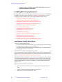
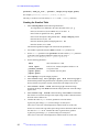
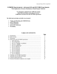
The UNITYINOVA microimaging module consists of a one-phase continuous-frequency
synthesizer, one rf waveform generator, three gradient waveform generators, three gradient
amplifiers, a linear rf preamplifier, and the basic microimaging module. The basic module
is not frequency specific. The basic module provides for rf and gradient waveform
generation, gradient signal conditioning, gradient current drive amplification, a safety
interlock system. All microimaging pulse sequence timing remains under master control of
the pulse controller board.
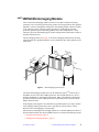
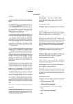
The microimaging cabinet (see Figure 1) for the microimaging module houses the safety
interlock board, three gradient amplifiers, a power distribution unit, and a gradient system
status panel.
NMR
Cons
ole
Micro
imagin
Cabin
g
et
eo
er
put
om
st C
Ho
sha
iko
Se ter
t
Plo
Vid
Magn
et
Figure 1. Microimaging System Layout
The Varian microimaging module can be can be installed on Varian UNITYINOVA 300- or
400-MHz, 89-mm vertical bore NMR spectrometer. This module adds the X, Y, and Z
gradient capabilities for microimaging experiments. Many of the hardware and software
operations and utilities of the liquids spectrometer, particularly those involved with 2D
NMR, remain the same.
Field mapping of all magnets is recommended for good homogeneity over large volumes
(microimaging samples greater than 5 mm), especially for systems with 23 or more
RT shims coils. Field mapping is sold separately.
Instructions for installing the microimaging module on UNITYINOVA NMR spectrometers is
described in this manual. The major installation steps are covered in the following sections:
• Preparing for Installation, page 10
• Installing Microimaging Hardware, page 12
01-999070-00 A0499
UNITYINOVA
Microimaging Hardware Installation
9
UNITYINOVA
Microimaging Module
• Configuring VNMR for Microimaging, page 21
• Testing and Verifying the Gradient System, page 22
• Calibrating and Configuring Gradient Strength, page 23
The last section in this manual, System Protection and Status, page 27, describes the
microimaging hardware.
Preparing for Installation
Installing and testing the microimaging module requires the equipment listed below:
• Dual-trace oscilloscope capable of accurate peak-to-peak voltage (Vpp) and
measurements between 9 and 200 MHz (Factory installations also require a digital
oscilloscope with memory.)
• 500-W, 30-dB attenuator
• Spectrum analyzer
• Varian field service engineer tool kit
Complete the following steps before installing the microimaging module:
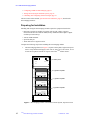
1.
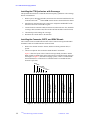
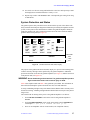
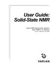
The microimaging cabinet (see Figure 2) requires a three-phase, high-current power
source. Verify that the main supply is 208 V/60 A, 240 V/50 A, 380 V/40 A, or 415
V/30A and is separate from the 20 A power line to the UNITYINOVA console.
AMP X
AMP X
AMP X
ALL AMPS
Status panel
WARNING
EMERGENCY
SERVICE
X gradient amplifier
TECHRON 7700 SERIES
Y gradient amplifier
TECHRON 7700 SERIES
Z gradient amplifier
TECHRON 7700 SERIES
Figure 2. Microimaging Cabinet with Gradient Control System, Open Front View
10
UNITYINOVA
Microimaging Hardware Installation
01-999070-00 A0499
UNITYINOVA
2.
Microimaging Module
Check the items in the shipping kit against the parts list provided in the kit. If all the
parts on the list are included in the kit, proceed to the next step. If anything is
missing, obtain it before proceeding.
WARNING: Equipment and tools used by the moving crew must be evaluated for
safety in the magnetic field. Install a plastic chain (or chain of other
nonmagnetlc material) at about 42 in. (107 cm) from the magnet body.
This serves as a reminder to prevent magnetic materials (consoles for
example) from being pulled Into the magnet body.
CAUTION:
3.
Keep metal objects away from the magnet. The strong magnetic field
of the dewar attracts ferromagnetic objects, such as compressed gas
cylinders, steel chairs, steel carts, and the microimaging cabinet.
Unless restrained, such objects can strike the magnet, causing
extensive damage to the probe, the dewar, and the superconducting
solenoid. Use only nonferromagnetic materials (such as plastics,
aluminum, wood, and stainless steel) in the area around the magnet.
Verify that there is enough room to accommodate the microimaging cabinet in the
floor plan of the laboratory (see the Installation Planning Guide). The following are
space guidelines:
a.
Measure the distance between the edge of the UNITYINOVA cabinet and the
centerline of the magnet.
b.
If this distance is greater than 185 cm (73 in), and only the microimaging
cabinet is going to be installed, then go on to step 6. If the distance is less than
185 cm (73 in), determine how much distance must be added to accommodate
the microimaging cabinet:
–
185 cm
(73 in)
c.
=
measured
distance
additional distance needed
Place the UNITYINOVA cabinet at the correct distance (the left edge of the
cabinet must be at least 48 inches away from the center of the magnet).
Disconnect all cables from the magnet leg and move them away from the right
side of the console.
WARNING: Only qualified maintenance personnel shall remove equipment covers
or make internal adjustments.
Dangerous high voltages that can kill or injure exist inside the instrument.
Before working inside a cabinet, turn off the main system power switch located
on the back of the console.
4.
Shut down the system.
5.
Remove the power connector from the rear of the UNITYINOVA cabinet.
CAUTION:
The following installation involves handling static-sensitive
equipment and printed circuit boards. Take all precautions necessary
to suppress electrostatic spikes and discharges near the devices:
stand on antistatic pads, wear natural fiber materials, and use a
grounded antistatic wristband before touching any equipment, etc. Be
especially careful with red-colored boards. These are extremely static
01-999070-00 A0499
UNITYINOVA
Microimaging Hardware Installation
11
UNITYINOVA
Microimaging Module
sensitive. Failure to suppress electrostatic discharges can result In
permanent damage to components.
Installing Microimaging Hardware
The procedures in this section describe how to install the various parts of the microimaging
hardware. Be sure that you have completed Preparing for Installation, page 10, before
continuing with the installation. This section contains the following procedures:
• Installing the Imaging Switch Board, this page
• Installing the PTS Synthesizer with Overrange, page 14
• Installing the Connector, DECC, and SDAC Boards, page 14
• Installing the Gradient Waveform Generator Boards, page 15
• Installing the Voltage Regulator Module, page 17
• Connecting the Cables, page 17
• Finishing the Hardware Installation, page 18
• Testing the DECC Accessory, page 18
• Connecting the Power, page 19
• Installing the Junction Unit and Gradient Harness, page 19
• Installing the Air Cooling System, page 20
• Installing the Preamplifier Attenuator, page 21
• Installing Gradient Coils and the Microimaging Probe, page 21
Installing the Imaging Switch Board
There are two imaging switch boards:
• For systems with the Oxford ribbon cable style of room temperature shims, the board
to install in the shim supply is Part No. 01-903922-xx.
• For systems with the Oxford red tube room temperature shims, the board to install in
the shim supply is Part No. 00-993958-xx.
The installation procedure for each board is quite similar.
To verify whether the imaging switch board is installed, look at the back of the shim power
supply. If there are three triax connectors (X, Y, and Z1), the board is installed and you can
skip to Installing the PTS Synthesizer with Overrange, page 14.
The Imaging Switch board disconnects the X, Y, and Z1 room temperature shim coils from
the output of the Varian shim supply, and connects the Varian outputs to the digital eddy
current compensation (DECC) connector boards (X, Y, and Z) whenever the corresponding
Techron gradient amplifier is enabled. This enables X, Y, and Z1 shimming through the
gradient coil set.
Imaging Switch Board, Part No. 01-993958-xx
12
1.
Disconnect the power from the shim power supply and disconnect the shim coil
cable.
2.
Carefully remove the shim power supply from the console.
3.
Remove the cover from the shim power supply.
UNITYINOVA
Microimaging Hardware Installation
01-999070-00 A0499
UNITYINOVA
Microimaging Module
In the rear of the supply are two D shell connectors J908 and J909 that are mounted
to a removable plate.
4.
Remove the two screws fastening the plate to the rear wall of the shim supply, and
remove the plate. Remove the two connectors from this plate.
5.
Connect the 37-pin D shell connector into J1 of the Imaging Switch board.
6.
Tiewrap the unused 9-pin D shell connector so it won’t rattle around.
7.
Mount the Imaging Switch board, which has its own metal bracket, inside the supply
in the spot vacated by the removable plate.
8.
Replace the shim supply cover and replace the shim supply back into the console.
9.
Reattach the shim coil cable to J908 of the Imaging Switch’s metal bracket.
10. Go to Connecting the Imaging Switch Board, this page to connect the cables.
Imaging Switch Board, Part No. 01-903922-xx
1.
Disconnect the power from the shim power supply and disconnect the shim coil
cable.
2.
Carefully remove the shim power supply from the console.
3.
Remove the cover from the shim power supply.
In the rear of the supply are two D shell connectors J908 and J909 that are mounted
to a removable plate.
4.
Remove the two screws fastening the plate to the rear wall of the shim supply, and
remove the plate. Remove the 64-position pin ribbon cable connector from this plate.
5.
Connect the 64-pin ribbon cable connector into P907 of the Imaging Switch board.
6.
Mount the Imaging Switch board, which has its own metal bracket, inside the supply
in the spot vacated by the removable plate.
7.
Replace the shim supply cover and replace the shim supply back into the console.
8.
Reattach the shim coil cable to J907 of the Imaging Switch’s metal bracket.
9.
Go to Connecting the Imaging Switch Board, this page to connect the cables.
Connecting the Imaging Switch Board
1.
For Part No. 01-993958-XX, connect the Oxford room temperature shim coils to
J908 of the Imaging Switch board. J908 is located on the rear of the Varian shim
supply.
For Part No. 01-903922-XX, connect the Oxford room temperature shim coils to
J907 of the Imaging Switch board. J907 is located on the rear of the Varian shim
supply.
2.
Connect the cable from J6 of the Safety Interlock board to J2 of the Imaging Switch
board. J2 is located on the rear of the Varian shim supply.
3.
Connect the three blue twinax cables from the DECC connector boards, to the X, Y,
and Z1 connectors of the Imaging Switch board. The twinax connectors are located
on the rear of the Varian shim supply.
4.
Make sure the power cable is connected.
01-999070-00 A0499
UNITYINOVA
Microimaging Hardware Installation
13
UNITYINOVA
Microimaging Module
Installing the PTS Synthesizer with Overrange
This procedure describes how to install the PTS-500 frequency synthesizer with overrange,
Part No. 00-990880-01.
1.
Remove power, disconnect all cables, and remove the connector board from the rear
of the PTS unit in the UNITYINOVA NMR console. Remove the PTS from the cabinet.
2.
Install the new PTS-500 unit in the vacant space. Adjust the 10 MHz OUT of the
PTS-500 to between 8 and l0 dB of signal.
3.
Connect the PTS Connector board (00-992106-00) to the PTS-500. Also, install the
overrange cable (00-993015-00) between the PTS-500 and PTS Connector board.
4.
Check the dip switch settings for overrange.
5.
Reconnect the coaxial cables to the PTS-500.
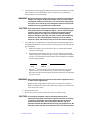
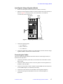
Installing the Connector, DECC, and SDAC Boards
The Connector board is installed into the back of the rf control card cage and the DECC
and SDAC boards are installed into the connector board.
1.
Remove the old DAC and GCU boards, and the waveform generator cable, if
present.
2.
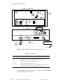
Choose two adjacent slots in which to install the DECC and SDAC.
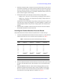
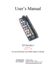
Figure 3 shows the layout of the rf control card cage. Ideally, the DECC and the
SDAC boards are installed next to the lock transceiver controller boards, shown as
A through F in Figure 3 (note that on imaging systems, if there is no DIFF AMP
board installed, the Lock Transceiver Controller board is not needed and slot 7
becomes a spare slot).
DECC
SDAC
spare slot
WFG X
WFG Y
WFG Z
Magnet leg & Interface
Amp & Route
Transmitter Controller 1
WFG 1 (optional)
Transmitter Controller 2
WFG 2 (optional)
Transmitter Controller 3
F
WFG 3 (optional)
E
Transmitter Controller 4
D
WFG 4 (optional)
C
Receiver Controller & Clock Generator
B
Lock Transceiver Controller
AP & F
HS & R
A
Slot Slot Slot Slot Slot Slot Slot Slot Slot Slot Slot Slot Slot Slot Slot Slot Slot Slot Slot Slot Slot
1
2
3
4
5
6
7
8
9
10 11
12
13
14
15 16
17
18
19
20
21
Figure 3. RF Control Cardcage, Front View, Showing Slot Assignments
14
UNITYINOVA
Microimaging Hardware Installation
01-999070-00 A0499
UNITYINOVA
3.
Microimaging Module
Install the Connector board (01-904736-00) into the back of the two slots selected
for the DECC and SDAC. Line up the Connector board in the back of the card cage,
above two open P2 connectors. Use the M2.5X8 screws provided (12-168209-00).
The Connector board provides power to the DECC and SDAC boards, and serves as
the P1 connector (upper) in the card cage.
4.
On the SDAC board, set the J8 jumper to select current or voltage mode:
• Jumper J8 out – B0 driver is in current mode, providing up to about 500 mA.
• Jumper J8 in – B0 driver is in voltage mode, providing a voltage signal to an
external current amplifier.
The B0 driver circuit on the SDAC can provide up to about 500 mA of current. For
coils where this would not be enough drive, an external amplifier is needed. For an
external amplifier, the B0 circuit provides a voltage signal to the external current
amplifier.
5.
Install the DECC and SDAC boards into the slots where the connector board has
been installed. The DECC board is on the left.
Installing the Gradient Waveform Generator Boards
The Gradient Waveform Generator boards are installed in the rf control card cage.
1.
Locate the Gradient Waveform Generator boards (01-902034-xx). Verify that their
jumpers and switches are correct for their respective gradients. See Table 1.
Table 1. Gradient Waveform Generator Board Jumper Settings
Jumper
Gradient
Channel X
Gradient
Channel Y
Gradient
Channel Z
Gradient
Channel W
J2
1-2
1-2
1-2
1-2
J8
1-2
1-2
1-2
1-2
J9
1-2
1-2
1-2
1-2
J10
1-2
1-2
1-2
1-2
J17
1-2
1-2
1-2
1-2
J16
Not Used for
Gradients
Not Used for
Gradients
Not Used for
Gradients
Not Used for
Gradients
Switch
2 Gradients
3 Gradients
4 Gradients
5 Gradients
SW-1
2
3
4
5
2.
Insert the Gradient Waveform Generator boards into the nearest three spare slots to
the right of the Smart DAC board, with X being the closest to the Gradient DAC
board.
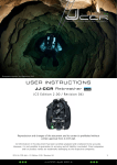
3.
Using the SMB cables that were used in the microimaging cabinet to provide
40 MHz to the Waveform Generator boards, connect a 40-MHz clock from the
Receiver Controller to each of the Waveform Generator boards. Use an SMB T
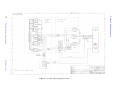
(58-180018-00) if not enough outputs are available. See Figure 4.
01-999070-00 A0499
UNITYINOVA
Microimaging Hardware Installation
15
Microimaging Hardware Installation
Microimaging Module
UNITYINOVA
UNITYINOVA
16
01-999070-00 A0499
Microimaging Interconnect
UNITYINOVA
Figure 4.
UNITYINOVA
Microimaging Module
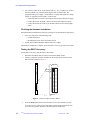
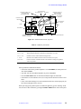
Installing the Voltage Regulator Module
1.
Remove the blank panel from the back of the rf cabinet, if necessary.
2.
Mount the voltage regulator module (01-905652-00) in the back of the rf cabinet, as
shown in Figure 5. Use the #10 screws, nuts, and washers (12-222060-08,
14-122010-00, and 14-202010-00).
RF cabinet
(back)
Digital
cabinet
Figure 5. Voltage Regulator Module Installation
3.
Connect the following leads:
• +15, to TB1001-7
• GND, to TB1001-8
• −15, to TB1001-9
4.
Connect the pigtail cable (with the 16-pin white Molex connector) from the voltage
regulator module to the back of the Connector board.
Connecting the Cables
The power and the gradient amplifier must still be off before connecting the cables, as
described in the steps below.
1.
Connect the mini DIN-8 patch cable (81-839724-00) between the DECC and the
SDAC boards.
2.
Connect the ribbon cable (01-905517-00) to the gradient waveform generators, to
the SDAC, and to the DECC.
3.
Connect J16 on the DECC board to 40 MHz, using the SMB Cable (00-992897-04).
Use the SMB T-adapter (58-180018-00) if necessary.
4.
Connect the twinax cables between the SDAC and the gradient amplifiers.
5.
Connect the B0 output from the SDAC to the coil or external amplifier, as
appropriate.
01-999070-00 A0499
UNITYINOVA
Microimaging Hardware Installation
17
UNITYINOVA
Microimaging Module
6.
For systems in which the X, Y, and Z shim fields (i.e., X1, Y1 and Z1) are created
from the gradient coils, install the shim adapter cable (01-905516-00). The
appropriate shim power supply—in which the X, Y and Z shim signals are voltage
signals, as opposed to current signals—must be used.
• Connect the male end of the 37-pin D-shell connector to the shim power supply.
• Connect the twinax “breakout” cables to the back of the Connector board.
• Connect the female end of the 37-pin D-shell connector to the shims (higher
order).
Finishing the Hardware Installation
Finish the hardware installation by turning on system power as described in the steps below.
1.
Turn on system power in the following order:
• Console main power
• RF and digital power on the front of the console
2.
Switch on the gradient amplifiers and the shim power supply.
The hardware installation is complete. To test the DECC accessory, go to the next section.
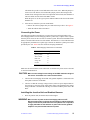
Testing the DECC Accessory
Test the DECC accessory using the steps in this section.
1.
Disconnect the ribbon cable (01-905517-00) from the DECC board.
2.
Connect a jumper between pins 68 and 66 on the 68-pin condo connector on the
DECC board, as shown in Figure 6.
DECC
Pin 68
Pin 66
J1
J1
Figure 6. Self-Test Jumper on DECC Board
3.
Press the Reset button on the front of the DECC board. This starts the self test.
A 10-Hz sine wave will be present at the DECC board outputs. Measure the sine
wave at the test points in the front of the board with an oscilloscope.
18
UNITYINOVA
Microimaging Hardware Installation
01-999070-00 A0499
UNITYINOVA
Microimaging Module
The LEDs also provide a visual indication of the 10 Hz wave. When the jumper is
removed, or if the board is reset without the jumper present, the board goes into
normal mode, waiting for the start of an experiment. In this mode, there should be a
total of 6 LEDs on at the front of the DECC board.
When the power is on, the 6 green power indicator LEDs on the front of the SDAC
should be lit.
4.
After the test, return the system to normal mode:
• Remove the self-test jumper that you connected in step 2 above. See Figure 6.
• Attach the ribbon cable to the DECC.
Connecting the Power
The following procedures describe how to connect the power and signal cables to the
microimaging cabinet. The microimaging cabinet is powered by a 3-phase source separate
from the power source for the rest of the UNITYINOVA system. The Power Distribution Unit
(PDU) is located at the bottom-rear of the cabinet. The PDU has a 15 foot cable that must
be appropriately terminated in a 3-phase type connector to match the 3-phase power outlet
provided by the user. Table 2 lists the connectors and plug destinations.
Table 2. Microimaging Cabinet Power Connections
Connectors
Plug Destinations
green: ground
G
white: neutral
W
black: hot
X
orange: hot
Y
red: hot
Z
Make sure the circuit breaker switch on the PDU is off before the power source at the wall
is connected and turned on.
CAUTION:
Make sure the voltage/current ratings of the PDU match the ratings of
the source. A mismatch can cause electrical failure.
1.
Check in the microimaging cabinet that each gradient amplifier is connected to the
three-phase connectors of the PDU.
2.
Check to see that the card cage voltage selector (at the rear power input module of
the card cage) is set to the proper single-phase voltage corresponding to the voltage
rating on the PDU. Check that the card cage is connected with the power cord to the
PDU.
Installing the Junction Unit and Gradient Harness
1.
Place the junction unit (00-969930-00) near the magnet.
WARNING: Make sure the ac power to the microimaging cabinet is OFF.
Disconnect the power cord from the microimaging cabinet. Although
safety circuits exist to protect the user if the junction unit is opened, it
is highly advisable to work with the ac power off since the gradient
amplifiers can put out lethal amounts of power.
01-999070-00 A0499
UNITYINOVA
Microimaging Hardware Installation
19
UNITYINOVA
Microimaging Module
CAUTION:
2.
Do not connect the harness leads to COMMON. This can cause
excessive currents to flow through the gradient coil, which might
damage the coil if the in-line fuses do not protect it properly.
Connect the heavy gauge gradient current harness (00-990910-00) to TB1 of the
junction unit. Connect the other end of the gradient current harness to each of the
gradient amplifiers. For each amplifier, the two harness leads should be connected to
OUTPUT and SAMPLED COMMON.
A 2.7-ohm resistor must go between SAMPLED COMMON and the amplifier
chassis—make sure the chassis end is making good electrical contact. The chassis
must also make good contact to the side of the gradient current harness.
3.
Connect the 37-pin D shell cable (00-990914-20) from J741 on the rear of the
microimaging cabinet to J801 of the junction unit.
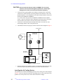
4.
Check that the air hoses are properly connected. See the air flow diagram in Figure 7.
Probe Cooling
Junction Unit
00-969930-00
Gradient
Coil
S801
S802
Pneumatics
00-991434-00
Magnet Leg
Probe
Cooling
00-990667-00
Filter
System Air
Figure 7. Air Flow Diagram
5.
When the gradient coil is installed, connect it to both J806 (inside the junction unit)
and to the 15-pin D shell J802 (mounted to the outside of the junction unit).
Installing the Air Cooling System
The gradient coil set and the microimaging probe use air for cooling. The air flow diagram
in Figure 7 shows the required connections. Depending on the air flow requirements of the
gradient coil, set the pressure sensor switch S801 and S802 accordingly.
20
UNITYINOVA
Microimaging Hardware Installation
01-999070-00 A0499
UNITYINOVA
Microimaging Module
Installing the Preamplifier Attenuator
This procedure describes how to install the preamplifier attenuator, which attenuates
the output of the observe preamplifier before the signal reaches the single mixer.
1.
Position the preamplifier attenuator (00-969935-00) on the floor near the magnet leg.
2.
Disconnect cable 00-958298-08 from the observe preamplifier output J5312 and
connect it to the preamplifier attenuator output.
3.
Use cable 00-958298-03 to attach the preamplifier attenuator input to the observe
preamplifier output J5312.
Installing Gradient Coils and the Microimaging Probe
Refer to the NMR Probes Installation Manual for the following procedures:
• Installing gradient coils
• Inserting a sample into the microimaging probe
• Installing and connecting the microimaging probe
Configuring VNMR for Microimaging
The microimaging software option can be installed at any time from the VNMR CD-ROM.
Refer to the VNMR and Solaris Software Installation Manual for more information.
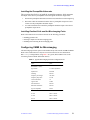
Run config to add gradients, using Table 3 as a guide. (WFG+SDAC refers to the
waveform generator and the Smart DAC board.)
Table 3. Typical Microimaging Software Configuration File
Label
Value
RF Channel 1 (Obs):
Type of RF:
U+ Direct Synthesis
Synthesizer:
PTS 500
Latching:
Present
Frequency Overrange:
100, 000
Frequency Step Size:
0.1 Hz
Coarse Attenuator:
79
Upper Limit:
63 dB
Fine Attenuator:
Present
Waveform Generator:
Present
Type of Amplifier:
Linear
Axial Gradients
X Axis
WFG + SDAC
Y Axis
WFG + SDAC
Z Axis
WFG + SDAC
01-999070-00 A0499
UNITYINOVA
Microimaging Hardware Installation
21
UNITYINOVA
Microimaging Module
Testing and Verifying the Gradient System
The following gradient system items are tested:
• Gradient controls
• Gradient compensation system
• Gradient coil assignments
Testing Gradient Controls
This procedure describes how to test the direct-write and shaped-write gradient control
paths. Perform gradient controls tests with the gradient amplifiers off or on standby.
Gradients are controlled through waveform generators.
1.
Test the direct-write control path as follows:
a.
Enter decctool and create a file.
b.
Enter rtp('/vnmr/parlib/gtest1') to recall the gtest1
parameter set.
c.
Set orient='xnn' to select the X channel. Set gro=32767 d2=0.001
tpwr=0 pw=0 nt=1000.
On the Smart DAC board’s “X” test point, you should measure 5 V for 2 ms.
Setting gro=–32767 should result in a –5 V measurement, and gro=0
should give a measurement of 0 V.
d.
2.
Repeat steps a and b for the Y and Z gradients by changing orient='ynn'
and then orient='znn', respectively.
Test the shaped-writer control path as follows:
a.
Enter rtp('/vnmr/parlib/gsh2pul') to recall the gsh2pul
parameter set.
b.
Set orient='xnn' gname='hsine' gro=32767 tpwr=0 pw=0
nt=1000.
c.
Set tro=0.0005 (i.e., 500 µs). Entering go should produce a one-half sine
wave at maximum of +5 V. The pattern should be smooth and continuous.
Change tro to tro=0.0100 (i.e., 10 ms) and enter go. The pattern should
still look smooth and continuous.
d.
Repeat steps a, b, and c for the Y and Z gradients, using entering
orient='ynn' for Y and orient='znn' for Z.
Testing the Gradient Compensation System
Each gradient compensation unit (X, Y, Z) requires the following functional tests:
1.
Make sure the gradient amplifiers are either off or in standby
2.
Enter the macro techron. This recalls the compensation file named techron for
Techron amplifier setup and sends it to the gradient compensation units. Any SDAC
duty cycle lights should be clear. The status panel is either clear or blinking until
manually reset.
3.
Enter gro=32767 d1=2 pw=0 tpwr=0 go. You should see the following
results on an oscilloscope:
• +5 V output at corresponding Gradient DAC output test point
• no amplitudes associated with the time constants
22
UNITYINOVA
Microimaging Hardware Installation
01-999070-00 A0499
UNITYINOVA
Microimaging Module
• 2.5 V (50% of 5 V) output voltage at output test point on the corresponding
SDAC O/P board because gain was set to 50%
• GCU duty cycle light blinking slowly (depending on thresholds)
For each gradient in turn, complete the following steps:
1.
Enter decctool to open the decctool window.
2.
With decctool, set files to global and select techron from the scrolling
list.
3.
Click the setup button.
4.
Set files to local, select temp.
5.
Set the overall gain to 40 and the duty cycle to 80 for each gradient. Click save.
With orient='xnn' for X, orient='ynn' for Y, or orient='znn' for Z,
you should see the following results from each gradient test point on the SDAC
board:
• 2 V (40% of 5 V)
• no duty cycle lights
• no amplitudes associated with the time constants
6.
Use decctool to set all amplitudes to 100% and repeat steps 2 to 5 above for each
gradient. A probe of all test points should show an exponential decay at the specified
time constant.
7.
Reset the files to global, select techron, and click the setup button.
Calibrating and Configuring Gradient Strength
Before the procedures in this section can be performed, the gradient coils must have been
properly matched to the amplifiers and the 90 pulse width calibration of the rf probe must
have been determined.
Creating the RF Pulse Calibration File
This procedure describes how to create the rf pulse calibration file.
• From previous results of the 90 pulse width, use thepulsecal command to create
the rf pulse calibration file as follows:
pulsecal('name of coil','pattern',length,flip-angle,power)
For example, pulsecal('rfcoil1','hard',75,90,55).
This entry is saved into a text file called pulsecal in the ~/vnmrsys directory.
Calibrating Gradient Strengths
This procedure describes how to calibrate the strength of the Techron gradient amplifiers.
1.
Set the overall gain setting in the decctool window to the appropriate gradient coil
maximum specifications (e.g., if the gradient coil has a maximum specification of
30 G/cm at 50 amps at 20% duty cycle, set the overall gain to 50 and duty cycle to
20 (or 15 to be on the safe side).
2.
Click save in the deccTool window.
3.
Place the cube-in-cube phantom into the coil approximately at the center of Z axis.
01-999070-00 A0499
UNITYINOVA
Microimaging Hardware Installation
23
UNITYINOVA
Microimaging Module
4.
Enter profile to load the profile parameter set.
5.
If the gradaxis parameter does not exist, create it:
create('gradaxis','string') gradaxis='z'
6.
Enter gzlvl1=8000,-8000 d1=1 d2=0.02. Set p1 to the 90° pulse, pw to
the 180° pulse, and tpwr to the appropriate level.
7.
Enter ga and then dssa to obtain the two profiles.
You might need to set the attenuator box to 20 dB or 30 dB to avoid ADC overflow.
8.
Adjust the length of the positioner until the two profiles coincide, which centers the
sample in the Z axis.
9.
Display one of the profiles (e.g., ds(1)) and measure the width of the profile
(in Hz) at 25% height at each end.
10. Enter setgcal and answer the following questions.
What is the size of the object (cm)?
What is the frequency spread (Hz)?
What is the gradient value (dac#s)
1.2
45500
8000
Answer y to the value of gcal calculated by the setgcal macro. If the maximum
gradient strength calculated is less than the specified value of the gradient coil,
change the gain setting for the Z gradient in decctool and repeat steps 8 through 11
until the value is reached. Write down the value of the maximum gradient strength
which will be used in creating the gradient table.
Creating the Gradient Table
1.
Enter creategtable and the following information:
Are all gradient axes calibrated to the same maximum value? y/n: y
Enter (m) for main coil, (h) for HPAG coil, (o) for other: o
Enter a name for gradient coil entry: gcoil1
Enter a brief description of this gradient table: Large imaging coil
Enter the boresize in (cm): 10
Enter the maximum gradient strength (gauss/cm): 30
Enter the risetime (µsec): 100
The maximum gradient strength is the value from the specification.
2.
Join another experiment and enter sems to load the sems parameter set.
3.
Set the rfcoil to the pulsecal file name and set the gcoil to the name of the
gradient calibration coil that was set in step 1 (e.g., rfcoil='imaging-coil'
gcoil='gcoil1')
4.
Set the following parameters:
thk=1
lro=3 lpe=3
p1=2000 p2=2000
p1pat='gauss'
p2pat='gauss'
5.
24
Slice of thickness in 1 mm
Field of view, readout, and phase encode to 3 cm
2-ms pulse width
Use Gaussian selective pulses
Enter imprep to set up the imaging pulse sequence.
UNITYINOVA
Microimaging Hardware Installation
01-999070-00 A0499
UNITYINOVA
Microimaging Module
6.
Enter orient='sag' nv=0 gro=gro,-gro d1=2 nt=1 ga to obtain
readout profiles along Z direction. Adjust the position of the sample up or down so
that the two profiles coincide, which centers the sample in the Z coil.
7.
Enter orient='trans' nv=64 tr=1 go to obtain an image. Transform the
image with ft2d and rotate the sample positioner so that the image appears level.
Enter go to obtain another image.
8.
Enter orient='sag' nv=128 ft2d to obtain an image and transform the data.
9.
Set the two cursors at the edge of the square image in the F2 dimension. Write down
the value of delta in Hz.
10. Calculate the value of gro in DAC units as follows:
gro (DACs) = gro (G/cm) / gmax (G/cm) * 32767
11. Enter setgcal to recalibrate gcal using the value of gro in DACs calculated
above. Note that the macro setgcal calculates gmax in G/cm.
12. Enter creategtable, which updates the gradient table file created in step 1 with
the new gmax value calculated in the previous step.
13. Set gcoil and sysgcoil to the gradient coil name and enter imprep to reset
gro, gpe, and other parameters in the sems experiment.
14. Obtain the image again and check the dimension of the cube image. Repeat
steps 8 through 13 until the dimension of the cube image is exactly 1.2 cm.
Calibrating Gradient Strengths (ecctool)
1.
Set the gain setting in the ecctool to the appropriate gradient coil maximum
specifications. For example, if the gradient coil has a maximum specification of
30 G/cm at 50 amps at 20% duty cycle, set the gain to 50 and the duty cycle to 20
(or 15 to be on the safe side).
2.
Create a file in the local directory (~/vnmrsys/imaging/eddylib), such as
main, with the X, Y, and Z gradients set to a gain of 50 and duty cycle of 15.
3.
Select setup in the ecctool window and execute a setup.
4.
Place the cube-in-cube phantom into the coil approximately at the center of the Z
axis.
5.
Enter profile to load the profile parameter set.
6.
If the parameter gradaxis is not present, create it:
create('gradaxis','string') gradaxis='z'
7.
Enter gzlvl1=8000,-8000. Set p1 to the 90° pulse and pw to the 180° pulse.
Set d1=1, d2=.02, and tpwr to the appropriate level.
8.
Enter ga and then dssa to obtain the two profiles.
You might need to set the attenuator box to 20 dB or 30 dB to avoid ADC overflow.
9.
Adjust the length of the positioner until the two profiles coincide, which centers the
sample in the Z. axis.
Creating the RF Pulse Calibration File
From the previous results of the 90° pulse width, create the RF pulse calibration file with
the following command:
01-999070-00 A0499
UNITYINOVA
Microimaging Hardware Installation
25
UNITYINOVA
Microimaging Module
pulsecal('name_of_coil','pattern',length,flip-angle,power)
For example, pulsecal('rfcoil1','hard',75,90,55)
This entry is saved into a text file called pulsecal in the ~/vnmrsys directory.
Creating the Gradient Table
1.
Enter creategtable and the following information:
Are all gradient axes calibrated to the same maximum value? y/n: y
Enter (m) for main coil, (h) for HPAG coil, (o) for other: o
Enter a name for gradient coil entry: gcoil1
Enter a brief description of this gradient table: Large imaging coil
Enter the boresize in (cm): 10
Enter the maximum gradient strength (gauss/cm): 30
Enter the risetime (µsec): 100
The maximum gradient strength is the value from the specification.
2.
Join another experiment and enter sems to load the sems parameter set.
3.
Set the rfcoil parameter to the pulsecal file name and the gcoil parameter
to the name of the gradient calibration coil that was set in step 1
(e.g., rfcoil='imaging-coil' gcoil='gcoil1').
4.
Set the following parameters:
thk=1
lro=3 lpe=3
p1=2000 p2=2000
p1pat='gauss'
p2pat='gauss'
Slice of thickness in 1 mm
Field of view, readout, and phase encode to 3 cm
2-ms pulse width
Use Gaussian selective pulses
5.
Enter imprep to set up the imaging sequence.
6.
Enter orient='sag' nv=1 gro=gro,-gro, d1=2 nt=1 and type ga to
obtain readout profiles along the Z direction. Adjust the position of the sample up or
down so that the two profiles coincide, which centers the sample in the Z coil.
7.
Enter orient='trans' nv=64 tr=1 and type go to obtain an image.
Transform the image with ft2d and rotate the sample positioner so that the image
appears level.
8.
Enter orient='sag' nv=128 to obtain an image. Enter ft2d to transform the
data. Set the two cursors at the edge of the square image in the F2 dimension. Write
down the value of delta in cm.
9.
Calculate the value of gain for the Z gradient in ecctool as follows:
Z gain (new gain setting)=gain(current setting in ecctool)*factor
where factor is the ratio of the displayed size and the actual size of the cube.
Set the two cursors at the edge of the square image in the F1 dimension. Write down
the value of delta1 in cm. Calculate the value of gain for the X gradient.
Y gain (new gain setting)=gain(current setting in ecctool)*factor
where factor is the ratio of the displayed size and the actual size of the cube.
26
UNITYINOVA
Microimaging Hardware Installation
01-999070-00 A0499
UNITYINOVA
Microimaging Module
10. In ecctool, save the new setting and load the file to the GCU and repeat step 8 until
the displayed size in both dimensions is exactly 1.2 cm.
11. Repeat steps 8 and 9 with orient='cor' and adjust the gain setting for X using
F1 dimensions.
System Protection and Status
The gradient system safety interlock board is located on the top side of the cabinet. The
safety interlock board interprets diagnostic information provided by the amplifiers and coil
system (via the junction unit) and determines whether the gradient amplifiers should be
enabled or disabled. The safety interlock board also drives the shim switch unit and the
gradient cabinet status panel (see Figure 8).
AMP X
AMP Y
AMP Z
SYSTEM
READY
ENABLE
DISABLE
ACTIVE
STANDBY
ENABLE
DISABLE
ACTIVE
STANDBY
ENABLE
DISABLE
ACTIVE
STANDBY
OUTPUT
INPUT
AC LINE
TEMP
DUTYCYC
OUTPUT
INPUT
AC LINE
TEMP
DUTYCYC
OUTPUT
INPUT
AC LINE
TEMP
DUTYCYC
WARNING
GRAD
COIL
ALL AMPS
READY
STANDBY
OPEN
HOT
RESET AMPS
OUT
J UNIT
LED TEST
COOLING
EMERGENCY
Code for LEDs
Green
Yellow
SERVICE
Red
Figure 8. Gradient Interlocks and Status Display
The purpose of the gradient interlock and status display is to prevent serious damage that
could be caused by the high currents produced by the gradient amplifiers. Additional
protection and status is built into the gradient amplifiers (see Figure 9). and the fuse block
in the junction unit (see Figure 10).
WARNING: Do not disable the gradient interlock. The gradient amplifiers produce
high currents that could result in serious injury or death.
Table 4 lists amplifier faults and Table 5 lists gradients system faults. The information in
these tables should help the operator determine the cause of a fault indication.
A steady, nonblinking red light on any of the faults indicates that the fault is currently active
and needs correcting. A flashing red light indicates that the fault occurred previously but no
longer exists.
The normal mode for turning on the power to the gradient amplifiers is as follows:
1.
Set the READY/STANDBY switch on the front of each gradient amplifier to
READY.
2.
Set the ENABLE/DISABLE switch on the status display panel to DISABLE for
each amplifier (the yellow STANDBY LED will go on).
3.
Power on each amplifier with its circuit breaker (rear of amplifier chassis).
01-999070-00 A0499
UNITYINOVA
Microimaging Hardware Installation
27
UNITYINOVA
Microimaging Module
Front View, Cover Removed
MASTER
CROWN
CONTROL
BOARD
T100--INPUT
Current Monito
Output
20 A/V
T105--GND
R108 R109
T103-B5
B6
OVER
VOLTAGE
READY
G
Y
OVER
TEMP
Y
STANDBY
FAULT
Y
R
OVERLOAD
Y
R117
OFFSET
MANUAL
RESET
RUN
RESET
Ground
Shield
Gradient Coil
Load
Back View
O
U
T
P
U
T
S
SAMPLED
COMMON
OUTPUT
+
COMMON
(open)
-
2.7 OHM
INPUTS
_
+
INTERLOCK
J3
2.7 OHM
POWER SWITCH
X
Interlock Connector Board
Input from
Gradient
Compensation
Board
Y
Z
Power
Distribution Box
Safety Interlock Board
(at bottom of cabinet)
Input Power
Figure 9. Gradient Amplifier, Front View (top), Back View (bottom)
Table 4. Amplifier Faults
Display
Meaning
OUTPUT
INPUT
AC LINE
TEMP
DUTYCYC
Voltage to gradient coil is too high; occurs when load is open.
4.
28
Input from GCU is too high and gives too much power to the coil.
Input line voltage is too high by 10% or more.
Output transistors or amplifiers are too hot.
Input from GCU is too high and gives too much power to the coil. The duty
cycle threshold value is set by the user from the ecctool window.
Press the RESET button on the status panel. If no faults occur, the READY LED and
all three ACTIVE indicators will light.
UNITYINOVA
Microimaging Hardware Installation
01-999070-00 A0499
UNITYINOVA
Air Hoses Out:
To Gradent Coil
To Probe
Gradient Cables Out:
(3 twisted pairs)
To Gradient Coils
Microimaging Module
Interlock Signals In:
Themocouples,
Coil Out Switch
Air Pressure
Switches
J805
"Junction Open"
Microswitch
Air Pressure
Guage
Latch
0 60
Hinges
J803
38
20
Fuse Block
+ -
+ - + -
Z
Y
Gradient Cable in from
Gradient Amplifiers
J804
19
X
1
J801
Air Hoses In
Safety Interlock Board
Figure 10. Gradient Junction Unit, Top View
Table 5. Gradient System Faults
Display
Meaning
COIL OPEN
COIL HOT
COIL OUT
J UNIT
COOLING
Load is open (coils, cables, or fuses).
Thermocouples inside the coil measure a temperature over 75°C.
Gradient coil set is removed from the magnet bore.
Interlock in the Gradient Junction Unit is not made (cover open).
Pressure switches on Gradient Junction Unit indicate cooling air to gradient
coils is not present.
Other operational considerations include:
• If the slide switch on the gradient amplifier is set to STANDBY, the status panel will
also read STANDBY.
• Any fault will cause all enabled amplifiers to go into STANDBY.
• Press the LED TEST button to check that all indicator lights are functional.
• If the DUTY CYCLE indicators are on, do a setup from the decctool window to clear
them.
• If any of the cables leading to J5 on the interlock board are not connected properly, all
the system fault lights will be on solid.
When powering up the gradient system, the indicator lights may go into “blinking” mode.
You can remove this condition by pressing the RESET AMPS button on the status panel.
01-999070-00 A0499
UNITYINOVA
Microimaging Hardware Installation
29
UNITYINOVA
30
Microimaging Module
UNITYINOVA
Microimaging Hardware Installation
01-999070-00 A0499
Index
Index
A
AC LINE fault, 28
active fault, 27
ACTIVE indicators, 28
air cooling system, installing, 20
air flow, 20
amplifier faults, 28
automatic teller machine (ATM) cards caution, 7
H
hardware
description, 9–29
installation, 18
helium contact with body, 6
helium gas flowmeters caution, 8
high-power amplifiers cautions, 8
I
B
imaging switch board, 12, 13
INPUT fault, 28
installation preparation, 10
installing microimaging hardware, 12–21
blinking mode, 29
C
cables, connecting, 17
cautions defined, 5
COIL faults, 29
config command, 21
connecting power, 19
connector board, 14
control paths, testing, 22
cooling air installation, 20
COOLING fault, 29
credit cards caution, 7
J
J UNIT fault, 29
junction unit, 19
L
LED TEST button, 29
M
D
DECC accessory
testing, 18
DECC board
installing, 14
DUTY CYCLE indicators, 29
DUTYCYC fault, 28
E
ecctool window, 29
ENABLE/DISABLE switch, 27
magnet quench warning, 6
magnetic media caution, 7
metal objects warning, 5
microimaging
cabinet, installing, 19
hardware, installing, 12
software, 21
microimaging probe
inserting a sample, 21
installing and connecting, 21
modifying the instrument, 6
N
F
fault status light, 27
field mapping, 9
flammable gases warning, 6
nitrogen contact with body, 6
nitrogen gas flowmeters caution, 8
O
observe preamplifier, 21
OUTPUT fault, 28
G
gradient
amplifiers, 27, 28
coils, installing, 21
controls, testing, 22
current harness, 20
interlock display, 27
junction unit, 29
status display, 27
strengths, 23, 25
system faults, 29
system, testing, 22
table, creating, 24, 26
gradient waveform generator
board, installing, 15
01-999070-00
A0499
P
pacemaker warning, 5
power
cables, connecting, 19
connecting, 19
distribution unit, 19
preamplifier attenuator, 21
prosthetic parts warning, 5
PTS frequency synthesizer, installing, 14
UNITYINOVA
Microimaging Hardware Installation
31
Index
R
radio-frequency emission regulations, 8
READY LED, 28
READY/STANDBY switch, 27
relief valves warning, 7
removable quench tubes warning, 7
RESET AMPS button, 29
RESET button, 28
RF pulse calibration file
calibrating and configuring, 23
creating, 25
S
safety interlock board, 27
safety precautions, 5, 7
sample, inserting into microimaging probe, 21
SDAC board, installing, 14
signal cables, connecting, 19
slot assignments, rf control cardcage, 14
solids high-power amplifiers caution, 8
STANDBY LED, 27
T
techron macro, 22
TEMP fault, 28
U
upper barrel warning, 6
V
VME cardcage, 9
VNMR, configuring, 21
voltage regulator module, installing, 17
VT experiment warning, 6
W
warnings defined, 5
32
UNITYINOVA
Microimaging Hardware Installation
01-999070-00 A0499