1
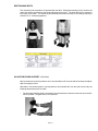
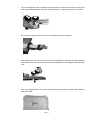
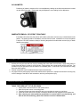
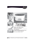
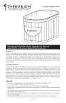
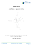
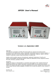
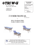
FOR CUSTOMER
ASSISTANCE
As a future reference, we suggest you record the information
listed below for quick accessibility:
Model No.: _________________
Serial No.: _________________
Purchase Date: _____________
1700 Gervais Ave, Maplewood, MN 55109
800-635-1312 · www.wrmed.com
Tri W-G® Service:
1-800-437-8011
USER MANUAL
Part No. 920-002-022
For
WR.S1
Tilt Table with Trendelenberg
Read this user manual carefully
before using WR.S1 Table
Limited Warranty Registration Card Enclosed
TABLE OF CONTENTS
INTRODUCTION........................................................................................................................................................1
UNCRATING AND TABLE SET UP ...........................................................................................................................1
ORGANIZATIONAL MEASURES...............................................................................................................................2
HANDSET CONTROL OPERATION/FUNCTION......................................................................................................3
SPECIAL NOTICES...................................................................................................................................................4
GENERAL SAFETY INFORMATION.........................................................................................................................4
SAFETY/PRECAUTIONARY INSTRUCTIONS, SYMBOLS, & TERMS....................................................................5
SAFETY STATEMENT AND WARNINGS/HAZARD SYMBOLS USED.....................................................................6
WHEN USING TABLE................................................................................................................................................7
GENERAL INFORMATION........................................................................................................................................7
SERVICE PARTS LISTS............................................................................................................................................9
SPECIFICATIONS...................................................................................................................................................10
PREPARATION FOR USE.......................................................................................................................................11
MAINTENANCE.......................................................................................................................................................14
TROUBLESHOOTING.............................................................................................................................................14
WARRANTY.............................................................................................................................................................15
INTRODUCTION
Thank you for selecting the WR Medical Electronics Co.’s Tilt Table with Trendelenberg mode, Model WR.S1. The WR
Medical tilt table uses new state-of-the-art programmable technology with memory functions. This innovative technology enables one to store three different working table tilt positions with instant recall and absolute positioning of those
stored positions. This is accomplished through the programmable handset pendant which is user friendly. There is also
an optional foot control available.
Please read this manual thoroughly. DO NOT USE or OPERATE this tilt table until you have read this operations
manual. Failure to do so could result in personal injury or equipment damage. This manual should be considered
a permanent part of your table and should remain easily accessible.
UNCRATING AND TABLE SET UP
1. Inspect for any concealed damage or item shortage immediatley upon receipt. If shipment is short or mechandise arrives damaged, a notation must be made on the signed freight bill at time of delivery, and a damaged
order receipt obtained from the delivering carrier. Claims for merchandise damage or lost must be filed immediately with the delivering carrier. Once freight receipt is signed, customer assumes all legal responsibility for the merchandise, including damages. The legal obligation of a freight company is to deliver the freight
to the back of the truck. This does not including unloading. WR Medical Electronics Co. does not assume any
responsiblity for loss or damage of merchandise in transit. WR Medical Electronics Co. will, however, cooperate in any way they can if a claim is necessary. DO NOT return damaged merchandise to WR Medical, unless
instructed to do so. WR Medical will provide you with a Returned Goods Authorization (RGA) No., if applicable,
for any return. Any compensation for loss must come from the delivering carrier for merchandise damaged in
transit.
When removing the tilt table from the shipping crate:
1. Keep cardboard liner on top of table when removing table from crate, and while moving table down hallways
and through doorways to desired location. This will help in preventing damage to the frame and cushion.
2. Remove the support crating members below the top cushion frame, and foam blocks underneath the base
frame used during shipping with the appropriate tools. Take precautionary measures to avoid damaging the
table and its finish during the removal process.
Installation of table:
1. There is no assembly required.
2. Locate the table in an area having flat/level floors so the table is not distorted out of alignment. This allows the
caster brakes to function as intended. Avoid floors that are uneven, slanted, or having a slippery surface/finish.
3. Provide adequate space around table so that procedures and table functions can be performed safely.
4. Lock caster brakes when table is in position.
5. Connect power cord to hospital grade receptacle with 120 volts, single phase, 60 Hz power source, conforming
to applicable nationally recognized electrical codes.
6. Power Supply Cord (Mains Cord) serves as the table’s disconnect device. There is no separate switch to
operate the table or shut the device off, other than the power supply cord. DO NOT connect to an extension
cord.
Page 1
ORGANIZATIONAL MEASURES
If you have any questions that cannot be answered through the operating instructions, contact the manufacturer directly.
Location of the Operating Instructions:
The operating instructions can only serve you if you have them available at all times. For this reason, Always keep the
operating instructions where the equipment is being used.
Distributor and Manufacturer Contact Information:
Distributed by:
Manufactured by:
WR Medical Electronics Co.
1700 Gervais Avenue
Maplewood, MN 55109
[P] 800-635-1312
Tri W-G, Inc.
215 12th Ave NE
Valley City, ND 58072-0905
[P] 800-437-8011
Page 2
Page 3
SPECIAL NOTICES
The photography, drawings, specifications, technical information, and descriptions, etc., hereinafter called (“data”),
contained in this manual was based on the technical information available at the time of its publication; however, design
and data may have changed since its printing. Due to our continuous efforts toward product improvement, WR Medical
and the manufacturer reserve the right to make changes without prior notification at any time, in design specifications
or other improvements on its products without incurring obligations to add them to any previously manufactured device. If you have any questions regarding its content or do not understand the data as presented, please contact the
manufacturer’s customer service department for assistance and guidance.
Some photos shown may be provided by a vendor and/or manufacturer--used with permission.
Options or accessories shown, or described, may be available at an extra cost and may be offered only in conjunction
with the manufacturer’s standard products and subject to additional ordering requirements or limitations.
All measurements in this manual are nominal U.S./English and where applicable their metric unit customary equivalents.
WR Medical and/or the manufacturer do not assume any risk or liability for attachments, or their effects on this device,
if the attachments are not manufactured, sold by and expressly approved by the manufacturer of this tilt table. When
replacement parts are required, use only those replacement parts authorized by the tilt table manufacturer.
The manufacturer’s limited warranty assumes that the table is used as specified, maintenance is performed correctly,
and that service is done by certified professionals in their respective vocations.
We are certain your WR Medical tilt table will provide you with years of satisfactory service.
GENERAL SAFETY INFORMATION
Every possible circumstance that might involve a potential hazard cannot be anticipated. Therefore, the warnings in
this operator’s manual are not inclusive. If you feel there is an operating procedure, maintenance or work method not
covered by this operators manual, please contact WR Medical and/or the manufacturer.
Whenever you see this symbol,
it means “Attention! You and/or Your Patient’s Safety is Involved”.
Operating instructions must be GIVEN to, and READ by everyone before operating this device. All users ought to use
common sense and know the limitations and hazards associated with operating this device.
Page 4
SAFETY/PRECAUTIONARY INSTRUCTIONS, SYMBOLS, & TERMS
▪
▪
▪
▪
▪
▪
▪
▪
Please read the following safety information carefully.
Ensure all operators of this table have read this operator’s manual and have direct access to it.
Make sure the table is electrically grounded by connecting only to a grounded hospital grade receptacle confirming
to applicable electrical codes.
Never place your hands or feet, nor a patient’s hands or feet, near any of the working mechanisms of the table when
tilting the table.
Before performing any service related work or trouble-shooting, make sure the following points are observed:
• The table does not have a patient on it.
• The electrical plug has been disconnected from the power supply.
• The table is not operating.
• The table’s casters are locked to prevent moving.
During table operation, stop the table if anything unusual is observed or unusual sounds are heard.
When not using the table, pull the plug out of the receptacle in order to prevent unintentional operation.
Your tilt table is not an ordinary table. It is a medical device; failure to operate it correctly may result in serious injury.
Therefore, keep children from using it as a piece of gym apparatus.
Visual words are used to indicate the degree of hazards as well as to warn against unsafe practices that may cause
injury to the patient or operator. Each visual signal will be followed by appropriate safety instructions. These signal
words are not to be ignored--you and your patient’s safety are involved. The user should become familiar with
these symbols specific to the product being used. All the symbols listed below may not be used with regard to the
product shown in this manual. However, all the symbols have been included for the purpose of user recognition and to
inform the user of their meaning.
Please review the following Warning Symbols and Usage Hints, and take note of the meaning of each:
ATTENTION: Provides user information.
Page 5
CAUTION:
Indicates a potentially hazardous situation which, if not avoided, may result in minor or moderate injury.
WARNING:
Indicates a potentially hazardous situation which, if not avoided, could result in death or serious injury.
DANGER:
Indicates an imminently hazardous
situation which, if not avoided, will
result in death or serious injury.
SAFETY STATEMENT AND WARNINGS/HAZARD SYMBOLS USED
The manufacturer has constructively, and with protective measures, minimized the effects of existing hazards. Locate
and become familiar with the following safety statements/symbols and instructions fround on the Tilt Table WR.S1, and
the possible countermeasures given in each, respectively:
Page 6
WHEN USING TABLE
(also refer to “Preparation for Use”, Page 11)
1. Insure restraining belts are positioned correctly and properly fastened.
2. Restraining straps must be properly secured when using arm support(s).
3. As a convenience, the footboard can be removed once the table has been tilted to a horizontal position and is
not required to support the patient.
NOTE: Be sure to reinstall footboard when raising table to vertical position.
4. If the table’s tilt function fails and the position of the table could cause a serious injury or death hazard to the
patient, the patient should be immediately removed from the table. Assistance to remove the patient is required. Do no hesitate or delay in removing the patient from the table when serious injury or death hazard is
recognized.
GENERAL INFORMATION
TABLE COMPONENTS
Please check all components supplied with the WR.S1 and confirm they are not damaged before use.
If you find any damage or parts missing, please contact WR Medical or manufacturer’s customer service department (1-800-437-8011). DO NOT return damaged merchandise to WR Medical, unless
instructed to do so. WR Medical will provide you with a Return Authorization Number, if applicable, for
any return. Any missing components will be shipped immediately upon receiving notification of which
components are missing.
STANDARD COMPONENTS:
Restrainer Belt Set (two per table)
P/N 908-003-124 (each)
Footboard
P/N 612-029-000
Used to secure patient to the table. Application instructions are on the restraining belt itself.
To remove the footboard, rotate it clockwise and lift up
and forward, moving it away from the safety pin. Maintain a firm grip on the footboard when removing or installing it, as it is rather heavy.
Page 7
Handset
P/N 900-025-045
Handset is programmable and may be operated manually or using the preset keys to position the tilt top. Ref to
Handset Control Operation/Function Instructions (Page
3) or yellow card with handset instructions attached to
the table.
OPTIONAL ACCESSORY COMPONENTS:
Adjustable Arm Assembly (one assembly shown)
P/N 612-028-000
Allen Wrench (3/16”)
P/N 917-000-166
Allen wrench used to adjust Arm Assembly.
Page 8
SERVICE PARTS LISTS
QTY.
PART NUMBER
DESCRIPTION
1
900-010-102
Actuator, Tilt
1
900-010-104
Control Box
1
900-025-045
Handset, Programmable
1
903-001-061
Caster, Total Lock
1
908-003-124
Belt, Restrainer
1
903-002-023
Bumper, GBR-7
1
612-905-000
Cushion
Page 9
PICTURE
SPECIFICATIONS
TILT TABLE WITH TRENDELENBERG--MODEL WR.S1
LENGTH:
78”
WIDTH:
28”
HEIGHT:
33”
TILT RANGE:
0 to 85 degrees (horizontal to vertical)
TRENDELENBERG:*
0 to -12 degrees
FRAME:
Lower frame (electric weld mechanical, round tube).........................................3” OD x 11 GA x 7 GA
Upper frame.................................................1-1/2” OD x 11 GA
CASTERS:
4- 5” casters with brake
TABLE TOP MATERIAL:
2” foam cushion over non-translucent sub-structure and steel frame
BELTS, RESTRAINING:
2- 4” wide belts with hook and loop fasteners
TABLE, COVER AND PAD:
FIRE RETARDANT** Vinyl cover over 2” polyfoam (or equivilant) pad
FINISH:
Polyurethane Pearl Grey standard
ELECTRICAL:
Control Box: Input: 120VAC, 60 Hz, 6.5 Amps; Output: 24VAC, 18 Amps; Ports: 24VDC, 10 Amps
Tilt: electromechanical drive, 10.0 Amps, 24VDC. Electrical components UL Recognized, 60601-1.
PATIENT LOAD:
Maximum weight capacity.....................................350 lbs
WEIGHT:
Table......................................................................275 lbs
Table shipping weight............................................370 lbs
*Nominal adjustments stated.
**Flammability requirements for materials are those of the manufacturer and not that of WR Medical Electronics Co. This term and any corresponding data refer to typical performance in manufacturer’s test and should not be construed to imply the behavior of this or any other
material under fire conditions.
Every effort has been made to use accurate photography, drawings, product specifications and descriptions at the time of printing, However,
because of continuous, progressive product improvement, all specifications and descriptions are subject to change without notice.
Page 10
PREPARATION FOR USE
FOOTBOARD--INSTALL
To install the fooboard, place the table in a horizontal position. Stand facing the footboard end of the
table, with a firm grip on the footboard, rotate and engage the hole on the bottom right hand corner onto
the the footboard pivot pin. Rotate footboard counter clockwise into slots.
FOOTBOARD--REMOVE
To remove footboard, place the table in a horizontal position. Stand facing the footboard end of the
table, rotate the footboard clockwise and then pull towards yourself. Maintain a firm grip on the footboard while removing it.
POSITIONING THE PATIENT
With the table top in a vertical position, the patient can step onto the footboard with their back to the cushion.
Page 11
RESTRAINING BELTS
Two restraining belt assemblies are provided with the table. With patient leaning into the cushion, the
upper belt can be placed across the chest and below the arm pits. The lower belt is then secured in
the vicinity of the knees. The restraining belt assembly has a hook and loop closure design requiring a
minimum of 12” overlap engagement.
ADJUSTABLE ARM SUPPORT (OPTIONAL)
When procedures require the patient’s arm to be extended out 90° from the side of the body, the adjustable arm support is used.
With table in a horizontal position, and the patient’s arm extended 90° from the side of their body, the
following adjustments are then made:
•
The horizontal adjusting knob is loosened (counterclockwise) to allow the armrest to swivel out 90°
from the patient. To tighten knob, turn clockwise.
Page 12
•
The vertical adjusting knob is loosened (counterclockwise) to allow the armrest to be slid up or
down to the desirable location along the restraining belt bar. To tighten the knob, turn clockwise.
•
Secure the loop strap on each arm rest once the patient’s arms are in position.
•
Minor adjustments of the tilt of each rest can be accomplished by loosening the ball and socket
located under each arm rest, move the rest into the desired position, and tighten the ball and socket
joint.
•
This is accomplished with a 3/16” plastic T-handle allen wrench which is stored under cushion at
head end of table.
Page 13
INCLINOMETER
Positioning of patient in degrees of tilt is accomplished by reading the inclinometers which are located
on each side of the table. Inclinometer may be adjusted to zero reading for fine adjustment.
IMMEDIATE REMOVAL OF PATIENT FROM TABLE
If the table’s tilt function fails, the position of the table could cause a serious injury or death hazard to the
patient. The patient should be immediately removed from the table. Assistance to remove the patient
is required. DO NOT hesitate or delay in removing the patient from table when serious injury or death
hazard is recognized.
MAINTENANCE
1. Ordinary dirt may be removed from vinyl by washing with warm water and mild soap. Apply soapy water to
a large area and allow it to soak for a few minutes. Brisk rubbing with a cloth should remove most filth. The
procedure may be repeated in case of stubborn or imbedded grime. A soft brush my be used after the soapy
water has been applied.
2. Painted components can be washed with warm water and mild soap.
3. Any repair must be performed by trained and certified service personnel. Improper and incorrect servicing may
result in damage to the WR.S1 and accessories; and may cause patient injury.
TROUBLESHOOTING
TABLE TOP DOES NOT TILT UP OR DOWN
1.
2.
3.
4.
5.
Check power cord connection to main power source.
Make sure power source is receiving power.
Thermal protector may have activated, and you must allow the system to cool down.
Check the control box to see if power cord and/or handset are fully engaged into the power port.
After checking the aforementioned possibilities for reasons table is not functioning, and
table is still not functioning, please call customer service at 1-800-437-8011.
Page 14
LIMITED WARRANTY
This Product or Part is sold by Tri W-G®, Inc. under the limited warranties set forth in the following paragraphs. Such warranties are extended only with respect to the Purchase of the
Product or Part as new merchandise directly from Tri W-G®, Inc. or WR Medical Electronics
Co. and are extended to the ultimate customer purchaser of the Tri W-G®, Inc. Product or
Part.
Tri W-G®, Inc. warrants that each Product or Part sold hereunder shall be free of defects in
material and workmanship for the Product warranty period identified as follows:
Two Years: structural frame.
365 Days: upholstery.
(Please note the aforementioned limited warranty is limited to original owner and not transferable.)
in the case of Products and twelve months in the case of Parts from the date of delivery
from Tri W-G®, Inc. or WR Medical Electronics Co., whichever is the later. Should defects
appear in any Products subject to this limited warranty and Parts subject to this limited warranty sold hereunder within the respective limited warranty period, Tri W-G®, Inc. will repair
or replace under the terms of this limited warranty any defective Part or Parts or provide
new or remanufactured Parts when the defective Part or Parts are returned to Tri W-G®, Inc.
facilities at Buyer’s expense upon (20) days prior written notice to Tri W-G®, Inc. Buyer will
be charged for any replacement Parts when shipped to Buyer by Tri W-G®, Inc. When the
defective Parts are returned to Tri W-G®, Inc. pursuant to Tri W-G®, Inc. Returned Goods
Authorization (RGA) No., charges will be waived.
This limited warranty does not apply to any Products or Parts which have been damaged
through misuse, negligence or accident (including shipping damage) on the part of Buyer
or any third party. This limited warranty does not apply to any Product in which Parts other
than replacement Part or Parts approved by Tri W-G®, Inc. have been used if said Parts are
or may be the cause of failure.
FOR ANY BREACH OF WARRANTY, EXPRESSED OR IMPLIED, THE LIABILITY OF TRI W-G®,
INC. IS HEREBY EXPRESSLY LIMITED, AND SUBJECT TO THE TERMS HEREIN, TO THE REPAIR OR REPLACEMENT OF ANY PRODUCT OR PART WHICH SHALL APPEAR TO BE DEFECTIVE IN THE OPINION OF TRI W-G®, INC. THIS WARRANTY IS IN LIEU OF ALL OTHER WARRANTIES, EXPRESSED OR IMPLIED, INCLUDING WARRANTIES OF MERCHANTABILITY AND
FITNESS FOR A PARTICULAR PURPOSE. IN NO EVENT SHALL TRI W-G®, INC. BE LIABLE
FOR ANY SPECIAL, INCIDENTAL OR CONSEQUENTIAL DAMAGES. NO CLAIM FOR BREACH
OF WARRANTY FOR PRODUCTS OR PARTS FURNISHED HEREUNDER SHALL BE ASSERTED
AGAINST TRI W-G®, INC. MORE THAN TWENTY (20) DAYS AFTER THE EXPIRATION OF THE
WARRANTY PERIOD.
Page 15
Distributed by:
Manufactured by:
Phone: 1-800-635-1312
Email: [email protected]
1700 Gervais Avenue
Maplewood, MN 55109
Phone: 1-800-437-8011
Email: [email protected]
215 12th Avenue NE
Valley City, ND 58072-0905
Copyright© 2011 Tri W-G®, Inc. All Rights Reserved.