1
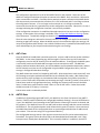
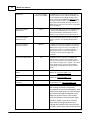
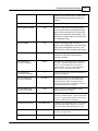
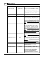
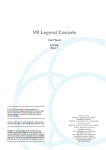
WASP User Manual
Revision: 2.2
(c) 2013 North Pole Engineering, Inc.
2
1
WASP User Manual
Introduction
WASP is a standalone unit providing a bridge for ANT+ devices to communicate wirelessly through
Wi-Fi networks, to other devices on the local network or over the Internet. Utilizing an NPE WiFiIT! module, 8-channel ANT+ receiver, on-board memory, power management circuitry and
rechargeable Li-Ion battery, WASP provides a data gateway for monitoring, recording and
analyzing ANT+ data remotely.
WASP connects ANT+ devices to wireless networks for monitoring and data collection purposes.
For example ANT+ home scales, pulse-oximeter monitors, and blood glucose monitors as well as
heart rate monitors and all other ANT enabled devices are all able to use this bridge module to
communicate their data to central monitoring stations via the WiFi network.
WASP is capable of receiving data wirelessly, from all certified ANT+ devices in the local area that
share the same ANT frequency. ANT+ device state is encapsulated as standard TCP-IP messages,
allowing it to be routed through local networks , through the Internet or directly to any Wi-Fi
connected device. WASP can be configured directly over the network with a configuration utility
or a web browser. WASP is also capable of sending data to any ANT radio in range that is capable
of receiving data packets.
An Application Programmers Interface is available to OEM partners, allowing WASP integration
into custom applications needing wireless connectivity to ANT enabled devices at ranges which
exceed the typical ANT radio reach. WASP Wi-Fi is able to join existing networks with common
security protocols, or create it's own access point allowing WASPs and application end point
devices (smart phones, tablet computers, Personal Computers, etc.) to join and share information
locally. WASP will run for up to six hours on its internal Li-Ion battery when hosting it's own
network as the network manager or up to 18 hours when joining an existing network. Battery life
is dependant on the amount of ANT traffic local to the WASP. For fixed installation
environments, WASP can be powered from a USB power source.
In addition to the periodic streaming protocols, WASP supports ANT-FS sessions when coupled
with a Wi-Fi application or web host to manage the authentication, and file transfer requests.
When WASP is configured in ANT-FS mode, it searches for ANT-FS beacons. When a beacon is
found, it commands the device sending the beacon to change frequencies and await the
authenticate command. The Wi-Fi endpoint application or web host is then notified of the
connection and control is passed off to the host device to manage the data transfer. WASP
monitors the transactions assisting in connection management during the transfer process. Once
the transfer is complete (the connection is either closed or lost), it resumes searching for other
ANT-FS devices.
WASP can also be used as a bridge between multiple ANT+ nodes in distributed ANT+ network
topologies. Since ANT+ is a personal area network, it has a typical range of approximately ten to
20 meters. If the ANT+ network is used as a mesh or hub and spoke topology, WASP can join
networks together that would normally not be able to communicate with each other because of
range limitations.
WASP is ANT+ certified and complies with all ANT+ device profiles.
(c) 2013 North Pole Engineering, Inc.
Introduction
2
3
Scope
This document provides a general introduction to using WASP. It includes information on button
operations, LED indicators, powering/charging the device, and Wi-Fi configuration.
3
What's New
Here are the updates for the latest release and previous releases.
Installation 2.0.17
1. ANTFS functionality added to download and forward files from ANTFS enabled devices.
2. Packet Saver mode added to concatenate multiple ANT packets into a single UDP packet to
reduce Wi-Fi network traffic.
3. Infrastructure Mode no longer uses a channel setting. It instead scans all channels for the
preconfigured network name.
4. WPS Mode added.
5. WASP now available with SPI mode ANT radios for higher throughput.
6. Updates for more intuitive usage and user feedback.
7. Multiple bug fixes.
Installation 1.6.1
1. Functional packet protocol change from point to point packet routing to local area UDP
multicast packets greatly increasing the number of Wi-Fi endpoints capable of receiving data
from a WASP while at the same time reducing the number of transactions required to supply
the data.
2. Support for both TCP and UDP type connections.
3. Enabled TCP connection for managing WASP configuration/control operations to a single
endpoint instead of UDP control from multiple end points requesting control.
4. Singular IP routing entry for supporting connection to web services outside the local Wi-Fi
network.
5. Improved user interface (button/LED) operation
6. Configured network persistence improvements which allow the WASP to reacquire the
network if the connection is lost.
7. Stage 1 implementation of onboard data storage of ANT data.
4
Quick Start Guide
The Quick Start Guide leads you through beginning to use the WASP. It is simple to use, yet
provides all the ANT, ANT+, and ANT-FS functionality you need to work with the ANT enabled
devices.
(c) 2013 North Pole Engineering, Inc.
4
4.1
WASP User Manual
Getting Started
Out of the box, the default configuration for the WASP is to create a Wi-Fi network when it is
turned on. The WASP needs to be configured in order to connect it to an existing Wi-Fi network.
This guide walks the user through the process of setting up the WASP for a specific operating
environment. Turning WASP on/off or changing operating modes is performed using the button
on the front panel of the device. This button is a membrane switch so feedback on button
presses is provided by the green and red LEDs above the button. The red LED is on the left side of
the label and the green LED is on the right side. The green LED is primarily used to indicate the
WASP is powered on and shows its operational state. With a repeated single blink once every
two seconds, the WASP is hosting its own limited AP network. With a repeated double blink
every two seconds, the WASP has joined an existing network. Refer to Modes of Operation for
additional details on the operating modes.
The red LED is used to provide change of state feedback, indicate the state of the internal battery
charger and to indicate progress when joining Wi-Fi networks. Refer to Status Indicators section
under WASP STARTUP for details on the operating modes of the red LED.
The mini-USB connector on the back of the WASP or the micro-USB connector on the side of the
WASP is used to charge the internal Lithium Ion battery using either a USB connection on a
computer, or a stand-alone wall charger. It can also be used to configure the WASP via an
application running on a computer connected to the USB cable.
The loop at the top of the WASP if it is present is used to secure the WASP to any attachment
point such as a lanyard or Velcro strap.
4.1.1
WASP STARTUP
The WASP is turned on by pressing the button for three quarters of a second. Once the green LED
illuminates, the WASP begins transitioning through the different modes. If released immediately
after one red flash, the WASP enters the Limited AP Mode. If released after two red flashes, the
WASP enters the Infrastructure Mode. If released after three red flashes, the WASP enters the
WPS mode. If released and quickly pressed after continuous, rapid flashing occurs on the red LED,
the WASP will restore factory defaults and power off.
AdHoc/Limited AP Mode
If the button is released after the green LED comes on and one flash occurs on the red LED, the
WASP enters either AdHoc or Limited AP Mode. This is indicated by a repeated single blink on the
green LED.
In this mode the WASP creates either an AdHoc or a limited AP infrastructure network with the
same name as its serial number. PCs, laptops, and smart phones can connect to this network and
will be assigned an IP address in the range 192.168.240.10 to 192.168.240.18. All WASP
functionality is fully available in Limited AP Mode. In addition, a webpage is accessible at
192.168.240.1 for AdHoc Mode, and "config.wasp.local" in LimitedAP mode for configuring the
(c) 2013 North Pole Engineering, Inc.
Quick Start Guide
5
Infrastructure Mode settings.
The choice between AdHoc and Limited AP mode is set in the WASP configuration. The factory
default mode is Limited AP mode. AdHoc mode is useful for maintaining the cellular data
connection when connected to an iOS product with cellular data capability. Since AdHoc devices
typically do not provide internet access, the iOS device continues to route data requests other
than WASP traffic to the cellular modem. Some devices are not capable of communicating in
AdHoc Mode, so Limited AP mode should be chosen for these devices.
Note: The battery will drain faster in AdHoc/Limited AP since hosting a network consumes more
power for Wi-Fi operations.
Infrastructure Mode
From power off, if the button is released after two flashes on the red LED, the WASP enters
Infrastructure Mode. This is indicated by a repeated double blink on the green LED. In this mode
the WASP attempts to join the pre configured infrastructure network. A rapid blink on the red
LED is used to indicate that the module is searching for the network, attempting to join,
authenticating, or negotiating an IP address. This is called the Network Join indicator. Once the
network association process is complete, the red LED turns off or switches to the Charging
Indicator if the USB cable is connected. The Network Join Indicator will come back any time
network connectivity is lost. All WASP functionality is fully available in Infrastructure Mode. The
configuration webpage is not available in Infrastructure mode.
WPS Mode
If the button is released after three flashes on the red LED, the WASP enters WPS Mode. This is
indicated by a repeated triple blink on the green LED. In this mode the WASP searches for a WPS
registrar and negotiates the exchange of SSID and WPA security information if one is found.
WASP uses the WPS push button method. This means you need to press the WPS button on your
AP/wireless router to put it into registrar mode and initiate the exchange. Do this after placing
the WASP in WPS Mode. The WASP will time out after two minutes if no WPS registrar is found.
If WPS fails or times out, the WASP will flash the red LED twice and return to Sleep Mode.
If WPS succeeds, the WASP will blink the green LED slowly three times, then update the settings
for Infrastructure Mode and immediately transition into Infrastructure Mode. The Network Join
Indicator will be active while the WASP is negotiating the new connection.
Restore Factory Defaults
Restore Factory Defaults is guarded by a specific button sequence. The button must be held from
power-off until the red LED begins flashing rapidly. It must then be released within three
seconds and quickly pressed again. The WASP will restore all settings to default and then power
off. This includes network settings for Infrastructure Mode.
If the button is held longer than three seconds or is not pressed quickly enough after release,
Restore Factory Defaults does not occur. This is indicated by three slow blinks on both LEDs
followed by transition to power off.
If the button sequence is performed correctly, Restore Factory Defaults does occur. This is
indicated by three slow blinks on the red LED only followed by transition to power off.
This special button press sequence is needed to prevent inadvertent resets if the button is held
(c) 2013 North Pole Engineering, Inc.
6
WASP User Manual
while in a pocket or bag.
Status Indicators on the Red LED
These status indicators are provided in Limited AP and Infrastructure Modes only. They are in
priority order. Indicators earlier in the list override indicators lower down.
Name
Description
Network Join
Indicator
Rapid blink on red LED. Provided in Infrastructure Mode only. Occurs while
searching for or negotiating a network connection. If the LED is rapidly flashing
for a WASP that was previously connected in Infrastructure Mode, that's a sign
network connectivity was lost.
Charging
Indicator
Provided if USB cable is connected. Slow blink indicates battery is charging. Solid
indicates battery is fully charged.
Battery
Indicator
One to four blinks indicating battery level. One blink is the lowest level. Four
blinks is the highest. Battery indication is provided by pressing and releasing the
button within 1 second while in Limited AP, Infrastructure, or WPS Mode. Battery
Indication is not provided if the Charging or Network Join Indicator is active.
WASP Startup Flowchart
4.1.2
WASP Configuration
Configuration of Network Settings for Infrastructure Mode
Out of the box Infrastructure Mode is setup to join a network with the name "wasp". This
network likely does not exist in most environments, so the network settings for Infrastructure
Mode will need to be updated. The WASP allows three different methods for setting the network
settings.
Webpage Update
The WASP can be started into the Limited AP Mode by pressing the button from the powered off
state and releasing after the green LED comes on and one flash occurs on the red LED. The WASP
will create an infrastructure network with the same SSID as its serial number. This network can be
joined by any PC, laptop, or smart phone. Open a web browser and navigate to "config.wasp.
local". The WASP will perform a scan of all networks in the area and present a webpage allowing
you to select from this list. Once you select a network, you are asked to enter a network
password and any advanced IP settings. Click "Next", then click "Save and Apply". The WASP then
updates the network settings for Infrastructure Mode. Note that the WASP is still in Limited AP
Mode at this point. You must power off and power back on into Infrastructure Mode.
WPS Mode
If you have physical access to your networks access point and the router supports Wi-Fi Protected
Setup, you can use this to set the network settings inside the WASP. Power the WASP on into
WPS Mode. From the off state hold the button until three red flashes have appeared on the red
LED, then release. The WASP enters WPS Mode, which is indicated by a repeated triple blink on
the green LED. Now press the WPS button on your network's access point. After a few moments
(c) 2013 North Pole Engineering, Inc.
Quick Start Guide
7
the WASP should see the WPS registrar hosted by the access point and begin a secure exchange.
The entire process takes several seconds. If the process is successful, the WASP will immediately
switch to Infrastructure Mode with the new network settings. This is indicated by three slow
blinks on the green LED, followed by a repeated double blink to indicate Infrastructure Mode. If
the process fails, the WASP sends two slow blinks on the red LED and returns to Sleep Mode.
WASP Configuration Utility
An iOS device or a PC connected to the same network as a WASP can be used to update its
network settings using the WASP Configuration Utility. This works in either Limited AP or
Infrastructure Mode. Use the Configuration Utility to connect to the WASP you wish to update
and enter the network settings in the network settings section. Click "Apply Settings" and
confirm your request by clicking "Continue". The settings are saved the WASP performs a reset
with the new settings. More on the WASP Configuration Utility is below.
WASP Configuration Utility
The WASP allows configuration of several settings in addition to the network settings for
Infrastructure Mode. A complete list of these settings, along with their default values, can be
found in Configurable Hardware Settings. The WASP is configured using the configuration utility,
which runs on either an iOS device or a Windows PC. The device performing the configuration
must be on the same Wi-Fi network as the WASP that is being configured. Configuration can be
performed in either Infrastructure or Limited AP Mode. If configuration is being performed from
an iOS device for a WASP in Limited AP Mode, the network created by the WASP must be joined
manually. This needs to be performed using the Settings application of the iPhone, iPad . If
using the Windows config application, the network is selected from within the application.
The configuration application lists all of the WASPs found on the network. Select one of the
WASPs to configure and select the option to connect to the WASP. Only one device is allowed to
open a connection to a WASP. If another device attempts to open a connection the WASP checks
with the currently connected device to find out if it is still connected and if it is willing to release
the configuration connect. If it is no longer on the network or it is willing to release the
connection the new device is granted access to the configuration interface. Otherwise it is sent a
message indicating the configuration interface is not currently available.
If the configuration connection is established the application then has access to the configuration
settings. A description of the settings is available in the Configurable Hardware Settings section
of this document. The default settings are found in Default Settings.
After the new settings are selected in the user interface, the changes are applied to the WASP by
choosing to apply the settings. When the WASP receives the command to apply the settings, the
internal configuration table stored in non-volatile FLASH memory is updated and the WASP resets
itself and attempts to join the preferred network using the new settings.Configurable Hardware
Settings. The WASP is configured using the configuration utility, which runs on either an iOS
device or a Windows PC. The device performing the configuration must be on the same Wi-Fi
network as the WASP that is being configured. Configuration can be performed in either
Infrastructure or Limited AP Mode. If configuration is being performed from an iOS device for a
WASP in Limited AP Mode, the network created by the WASP must be joined manually. This
needs to be performed using the Settings application of the iPhone, iPad . If using the Windows
config application, the network is selected from within the application.
(c) 2013 North Pole Engineering, Inc.
8
WASP User Manual
The configuration application lists all of the WASPs found on the network. Select one of the
WASPs to configure and select the option to connect to the WASP. Only one device is allowed to
open a connection to a WASP. If another device attempts to open a connection the WASP checks
with the currently connected device to find out if it is still connected and if it is willing to release
the configuration connect. If it is no longer on the network or it is willing to release the
connection the new device is granted access to the configuration interface. Otherwise it is sent a
message indicating the configuration interface is not currently available.
If the configuration connection is established the application then has access to the configuration
settings. A description of the settings is available in the Configurable Hardware Settings section
of this document. The default settings are found in Default Settings.
After the new settings are selected in the user interface, the changes are applied to the WASP by
choosing to apply the settings. When the WASP receives the command to apply the settings, the
internal configuration table stored in non-volatile FLASH memory is updated and the WASP resets
itself and attempts to join the preferred network using the new settings.
4.1.3
ANT+ Data
Once the WASP has established a network connection, it opens a UDP multicast socket at address
239.78.80.1. It then starts forwarding any ANT messages it receives from any ANT transmitter
configured to send on ANT RF channel 57 to the multicast address. If configured, the WASP opens
a unicast UDP socket and forwards ANT messages on that connection as well. The Multicast
Address and Port Number destination, the Unicast Address and Port Number destination, and the
ANT RF channel to monitor are all configurable using the WASP Configuration Utility. See the
settings in Configurable Hardware Settings.
The WASP allows two modes for forwarding ANT traffic. With Packet Saver mode turned off, each
ANT message received as packed and forwarded as an individual UDP packet. With Packet Saver
mode turned on, ANT messages are concatenated and sent together every 250ms (or quicker if
there is a lot of ANT traffic and packets are becoming too large). Each Wi-Fi packet is sent twice in
Packet Saver mode to help guarantee delivery, although the network traffic overall should be
lower. Packet Saver mode should be used if there is a lot of ANT traffic. Packet Saver mode
should be turned off if latency is a concern.
Packet Saver mode is enabled by default.
4.1.4
ANTFS Data
In addition to forwarding regular ANT traffic, the WASP can also listen for beacons from ANTFS
devices, if ANTFS mode is enabled (see Configurable Hardware Settings). Once an ANTFS beacon
is seen, the WASP will send a message to the ANTFS device informing it to switch its channel and
RF frequency. The WASP will reset its own ANT radio to these settings and then connect with the
ANTFS device. The only authentication mode allowed at this point is Passthru. Once connected,
the WASP downloads all files and forwards them to a preconfigured destination IP address and
port number. Files are sent using TCP for guaranteed delivery.
The Configurable Settings contain a few options to control which files can be downloaded and
forwarded. The Ignore Archive bit allows files to be downloaded and forwarded, even if they
have previously already been downloaded. This is normally disabled. In addition, the ANTFS
(c) 2013 North Pole Engineering, Inc.
Quick Start Guide
9
whitelists and blacklists allow for selecting or excluding specific file indexes and ANTFS device
types. These settings are described in further detail in Configurable Hardware Settings.
Once an ANTFS session is complete, a Disconnect command is sent to the ANTFS device with a
specific timeout. This timeout prevents the ANTFS device from going immediately back into
beacon mode, in which case the WASP would immediately connect again. The disconnect
timeout is configurable in Configurable Hardware Settings.
ANTFS mode is disabled by default.
Future Functionality:
Pairing and Pass Phrase Authentication
In the future the WASP will support passphrase authentication by requesting the passphrase from
the endpoint setup to receive the downloaded files. The WASP will read the serial number from
the ANT-FS client and send this serial number to the ANT-FS receive endpoint requesting the
passphrase in return. When pairing is set, the WASP will request the passphrase and then
provide the serial number and passphrase to the endpoint to save for future sessions.
4.2
Charging
WASP provides a mini-USB port to connect to a powered USB port on a computer or using a USB
(5V) wall transformer. This USB port is connected to the integrated Li-ion battery charger, which
monitors the status of the battery and controls the charge state. Once the battery reaches a full
charge, the charger stops the charging process and maintains a full charge level without
overcharging the battery so the WASP can remain connected to power indefinitely.
The red LED is used to provide feedback on the charging state of the WASP, both in the OFF and
ON states. When the WASP is attempting to join a Wi-Fi network in Infrastructure Mode, the red
LED is used to provide feedback on the progress of the connection process and does not provide
the feedback for battery charging.
When the red LED is flashing slowly the battery is charging. If the LED is a solid red, the battery is
fully charged.
5
Configurable Hardware Settings
There are a number of hardware settings that modify the operation of the WASP. The network
settings, described else where in this document, the configured static IP, and DHCP settings all
affect WASP operation. See WASP Configuration for instructions on how to access and modify
these settings. See the sub-topic Default Settings for a full list of configurable settings,
descriptions, and their default options.
5.1
Default Settings
User Setting
(c) 2013 North Pole Engineering, Inc.
Factory Default
Value
Description
10
WASP User Manual
WASP Name
Infrastructure Mode
Network SSID
17 character MAC
Address of the WASP
The WASP name is a 32 character field used to
provide an ASCII name to identify the WASP. This
can be changed using the WASP Configuration
Utility. Changing the WASP Name does not affect
the network name created in Limited AP Mode. It
does affect how the WASP identifies itself to any
WASP specific programs and utilities connected to
the same network.
wasp
A 31 character ASCII name used to identify the WiFi network the WASP attempts to join when in
Infrastructure Mode. An SSID Name must be a
minimum of 8 characters and a maximum of 31.
Infrastructure Mode
Network Security
Infrastructure Mode
Network PassPhrase
Infrastructure Mode DHCP
The security type used for joining an encrypted
network. Options include WEP, WPA, WPA2 or
None.
(Blank)
The network security key used when connecting to
a network in Infrastructure Mode. This may be a
WEP Key hex string if security is set to WEP, or a
passphrase if security is set to WPA/WPA2. A
WPA passphrase has a minimum length of 8
characters and a maximum length of 64
characters.
ON
The DHCP selection identifies if the WASP will
attempt to get an address from a DHCP server
when it joins the Infrastructure Mode network or
use a static IP configuration. If DHCP is turned off,
the IP configuration is given by the IP Address,
Subnet Mask, and Gateway IP settings outlined
below.
Infrastructure Mode IP
Address
192.168.89.10
IP address to be used in Infrastructure Mode if
DCHP is off. Not used if DHCP is on.
Infrastructure Mode Subnet
Mask
255.255.255.0
Subnet mask to be used in Infrastructure Mode if
DHCP is off. Not used if DHCP is on.
Infrastructure Mode
Gateway IP
192.168.89.1
Gateway IP address to be used in Infrastructure
Mode if DHCP is off. Not used if DHCP is on.
Packet Saver Enabled
ON
With Packet Saver mode turned off, each
ANT message received is packed and
forwarded as an individual UDP packet. With
Packet Saver mode turned on, ANT messages
are concatenated and sent together every
250ms (or quicker if there is a lot of ANT
traffic and packets are becoming too large).
Each Wi-Fi packet is sent twice in Packet
Saver mode to help guarantee delivery,
although the network traffic overall should
be lower. Packet Saver mode should be used
(c) 2013 North Pole Engineering, Inc.
Configurable Hardware Settings
11
if there is a lot of ANT traffic. Packet Saver
mode should be turned off if latency is a
concern.
RSSI Enabled
OFF
Not yet implemented.
Archive Ignore Enabled
OFF
In ANTFS mode, when downloading files
from an ANTFS device, the WASP normally
ignores files with the Archive bit set (files
that have already been downloaded). The
WASP can be made to ignore the archive bit
by enabling this flag.
ANT-FS Enabled
OFF
Allows connecting to ANTFS enabled
devices, downloading files, and forwarding
them to a preconfigured TCP server. See
ANTFS Data for a more complete description.
Created Network Type
Direct UDP Routing
Destination IP Address
Direct UDP Routing
Destination Port Number
Multicast UDP Routing
Destination IP Address
Multicast UDP Routing
Destination Port Number
Operational Mode
ANT Network Key Selection
Custom ANT Network Key
ANT Channel
(c) 2013 North Pole Engineering, Inc.
Limited AP
The WASP can create either an AdHoc
network or Limited AP network when
creating a network.
0.0.0.0
This specifies a single destination to forward all
ANT traffic. Since this need not be a multicast
address, it allows ANT traffic to be sent to a
remote network. Only one unicast destination
address may be specified for ANT traffic.
0
Used in conjunction with the Direct UDP Routing
Destination IP Address.
239.78.80.1
This specifies a multicast group address that
allows multiple devices to receive ANT traffic
forwarded by this WASP. Although multiple
devices may be specified, multicast transfers are
usually limited to the local network.
51113
Used in conjunction with the Multicast UDP
Routing Destination IP Address.
Streaming
Operational modes supported are Streaming,
Proximity, and Access Point. The proximity mode
also has a range setting that adjusts the distance
a device is detectable from the WASP.
ANT+ Network Key
The default eight byte Network Key can be selected
to be either Public, ANT+, ANT-FS, or Custom. If
Custom, the Custom ANT Network Key is used.
12,34,56,78,90,AB,CD,EF The custom network key is when ANT Network Key
Selection is set to Custom.
57
ANT radio frequency on which to listen for ANT
12
WASP User Manual
traffic and ANTFS beacons.
ANT-FS Destination IP
Address
192.168.240.10
Address of TCP server that ANTFS files should be
sent to during ANTFS file download and forward
operation.
Note: The default value is the same as the IP
address assigned to the first connected device in
Limited AP Mode. This is useful for testing.
ANT-FS Destination Port
Number
55555
Used in conjunction with ANT-FS Destination IP
Address.
ANT-FS Device Type White
List
All 0s
A list of Device Type, Device ID pairs that can be
used to whitelist specific ANTFS devices. Device
IDs can be wildcarded with a zero value for a
specific Device Type. The list holds up to eight
entries. Note that bit 7 (the pairing bit) of the
Device Type is masked out when comparing to the
whitelist. An empty list means the whitelist is not
used.
ANT-FS Device Type Black
List
All 0s
A list of Device Type, Device ID pairs that can be
used to blacklist specific ANTFS devices. Device
IDs can be wildcarded with a zero value for a
specific Device Type. The list holds up to eight
entries. Note that bit 7 (the pairing bit) of the
Device Type is masked out when comparing to the
blacklist. An empty list means the blacklist is not
used.
An entry in the Device Type Black List will override
any entries in the Device Type White List.
ANT-FS File Index White List
All 0s
A list of ANT-FS File Indexes to be whitelisted. Any
file indexes not in the white list are excluded from
download. An empty list means the whitelist is not
used.
ANT-FS File Index Black List
All 0s
A list of ANT-FS File Indexes to be blacklisted. Any
file index specified by the black list is excluded
from download. An empty list means the blacklist
is not used.
An entry in the File Index Black List will override
any entries in the File Index White List.
App Specific Disconnect
Disconnect Time Duration
0
30 seconds
Byte sent for the application specific disconnect
field when the ANT-FS session issues the
disconnect command
Disconnect time duration to specify to ANTFS
enabled devices. The time duration is sent as part
of the disconnect command after file download/
transfer is complete. It is the length of time the
device should wait before resuming ANTFS
beacons. This prevents the WASP from
immediately reconnecting. The disconnect time
(c) 2013 North Pole Engineering, Inc.
Configurable Hardware Settings
13
duration is specifiable in increments of 30
seconds.
6
Modes of Operation
The WASP has operational modes which are selectable via the membrane button located on
the front panel of the device. The button area is defined by the black circle just below the
red and green LEDs. See WASP STARTUP for a flowchart of the transition between different
modes and brief descriptions. Detailed descriptions are provided in this section.
Limited AP Mode
Infrastructure Mode
WPS Mode
Sleep Mode
Charging State
Restore Factory Defaults
6.1
Limited AP Mode
In AdHoc/Limited AP Mode the WASP acts as its own Access Point. The WASP creates either an
AdHoc or Infrastructure network with the same SSID as its serial number (i.e. "WA032105B4D").
The WASP can serve up to 8 IP addresses with a simple DHCP server. Note that the simple DHCP
server does not maintain a lease table. This means that any device that requests an address and
loses the connection may receive a different address when it attempts to reconnect. Also, if the
WASP creating the network is power cycled, it will restart the DHCP IP address assignments from
the initial IP address. This means devices that join the network can receive the same address as
other devices that had joined the network before the WASP was power cycled.
AdHoc/Limited AP Mode also provides a configuration webpage for the network settings used in
Infrastructure Mode. To access this webpage, first connect to the network being hosted by the
WASP with any PC, laptop, or mobile device. Then navigate to the URL 192.168.240.1 for AdHoc,
and "config.wasp.local" for Limited AP using any web browser. The WASP will perform a scan of
all networks in the area and then provide a list for selection within the webpage. There are also
options to set the security settings and IP configuration. If the browser is having trouble
connecting to "config.wasp.local" first make sure that your laptop is maintaining connection to
the WASP's network. If there is still a problem, your OS may be attempting to perform an MDNS
lookup on the URL only, and not a DNS lookup. Try entering "192.168.240.1" into the address bar
instead of "config.wasp.local". This problem has been observed occasionally with Mac OS X.
To enter Limited AP Mode, from a powered off state, press and hold the button until the green
LED comes on. Then release the button before any flashes occur on the red LED. The WASP will
immediately enter the AdHoc/Limited AP Mode and create the network. AdHoc/Limited AP
Mode is indicated by a repeated single blink on the green LED. All ANT operations are available in
AdHoc/Limited AP Mode.
Note: The battery will drain faster in AdHoc/Limited AP since hosting a network consumes more
power for Wi-Fi operations than simply maintaining a connection.
(c) 2013 North Pole Engineering, Inc.
14
6.2
WASP User Manual
Infrastructure Mode
In Infrastructure Mode the WASP joins a preconfigured network. The network settings are stored
in non-volatile flash and can be updated using three different methods. See WASP Configuration
for details. The default network settings are to join a network named "wasp" with WPA2 security
and a passphrase of "Hohoho97".
Infrastructure Mode always attempts to maintain connection with the preconfigured network.
When the WASP is either searching for the network, associating, authenticating, or negotiating an
IP address, the Network Join Indicator will be shown. This is a continuous rapid flashing on the
red LED. If this indicator occurs during normal operation, it means network connectivity was lost.
To enter Infrastructure Mode, from a powered off state, press and hold the button until the green
LED comes on and two flashes appear on the red LED. Release the button before three flashes
appear on the red LED. A repeated double blink pattern on the green LED indicates the WASP is in
Infrastructure Mode. Upon entering Infrastructure Mode, the Network Join Indicator will be
shown until the WASP is done joining the network. The Network Join Indicator will be shown
indefinitely if the WASP is unable to join the network. All ANT operations are available in
Infrastructure Mode.
6.3
WPS Mode
The WASP can join a Wi-Fi network via WPS (Wi-Fi Protected Setup), if the wireless Router or
Access Point is capable if participating in WPS operations. Wi-Fi Protected Setup (WPS) is a
computing standard for easy and secure establishment of a wireless network.
To initiate WPS mode, from an OFF state, press and hold the button for five seconds. After three
flashes occur on the red LED, release the button to place the WASP in WPS mode. WPS Mode is
indicated by a repeating pattern of three blinks on the green LED. Once the WASP is in WPS
mode, a simultaneous operation needs to be performed on the Router or Access Point. Refer to
the documentation for that unit for details on entering WPS mode.
In WPS mode the WASP is either searching for or exchanging security information with a WPS
registrar. This is your Wireless Router or Access Point if it is WPS capable. The process can take
several seconds to complete. It will time out after two minutes if no registrar is found.
If WPS is successful the new network settings will be stored in non-volatile flash and the WASP
will perform three slow flashes on the green LED. The WASP will then reset into Infrastructure
Mode.
If WPS is unsuccessful the old network settings are kept and the WASP will perform two slow
blinks on the red LED. The WASP will then return to Sleep Mode.
ANT operations are not available in WPS Mode.
6.4
Sleep Mode
The WASP is in the Sleep Mode when both LEDs are off. In this state both the Wi-Fi and ANT
radios are powered off and the WASP consumes a minimal amount of power. To enter Sleep
Mode from any Operational Mode (Limited AP, Infrastructure, or WPS), press and hold the button
until three slow blinks occur simultaneously on both LEDs.
(c) 2013 North Pole Engineering, Inc.
Modes of Operation
15
When the WASP is off, it is waiting for either a button press or USB charging connection. If the
button is pressed and held for at least three quarters of a second, the WASP will wake up and
enter the WASP Startup sequence.
If a USB cable is connected, the WASP will enter the Charging State but will remain off as far as
any ANT and Wi-Fi operations are concerned. USB Charging Sleep Mode is functionally equivalent
to Sleep Mode as far as button operations are concerned.
6.5
Charging State
When a USB cable is connected, the WASP is in the Charging State. It is in the Charging State
regardless of which mode it is in. Charging state is indicated during the Limited AP, Normal, and
Sleep Modes using the red LED. A slow blink indicates the battery is charging, and a solid on LED
indicates the battery is fully charged. The WASP can remain plugged in, at all times, to maintain
the battery in the maximum charge state. At times, the solid red will transition to blinking red
indicating the battery voltage has dropped to the point where the battery supervisor needs to
perform a maintenance charge cycle.
Notes:
The Charging Indicator is not provided in WPS Mode even though the battery is still charging.
The Network Join Indicator in Infrastructure Mode overrides the Charging Indicator.
In both Limited AP and Infrastructure Modes, the Battery Indication will not be provided if the
USB Cable is connected and the battery is charging. The Charging Indicator overrides it.
Being in the Charging State while in Sleep Mode does not affect push button operations. Any
user documentation that refers to a powered off state or Sleep Mode refers also to this state.
6.6
Restore Factory Defaults
Restore Factory Defaults is not a mode but an operation that can be performed from the powered
off state. Restore Factory Defaults will cause all user configurable settings to be restored to their
factory default state. This includes the WASP name, the Infrastructure Mode network settings,
ANTFS settings, and so forth. See Configurable Hardware Settings for a full list of user
configurable settings.
The following sequence will cause a Restore Factory Defaults operation:
1. Make sure the module is powered off in the Sleep Mode. It may also be in the Charging
State, with a USB cable connected.
2. Press and hold the button and wait for the following sequence.
3. 0.8 seconds to power on. Green LED comes on. (Keep holding the button).
4. 2 seconds to Infrastructure Mode. Two flashes on red LED. (Keep holding the button).
5. 2 seconds to WPS Mode. Three flashes on red LED. (Keep holding the button).
6. 5 seconds to Restore Factory Defaults Mode. Red LED is flashing continuously.
7. Release the button within three seconds of the WASP entering this state.
8. Quickly press the button again within half a second.
9. The WASP will indicate factory defaults have been restored by performing three slow
(c) 2013 North Pole Engineering, Inc.
16
WASP User Manual
blinks on the red LED only and then returning to Sleep Mode.
If the WASP reaches step 6 above but steps 7 and 8 are not performed correctly, factory defaults
will not be restored. This is indicated by three slow blinks on both LEDs followed by the WASP
returning to Sleep Mode.
7
WASP Hardware
7.1
Wi-Fi Key Features
FCC/IC/WiFi Certified
802.11 b/g/n Compatible (Requires 802.11b enabled on network)
Dual ARM7 Processors for application and networking
Small Form Factor (1.28” x 0.9” x 0.143”)
Security: WEP128, WPA-PSK and WPA2-PSK (TKIP / AES)
-40 to +85 °C Operating Temperature Range
5 Volt USB power
Splash Resistant Case
Integrated attachment loop
7.2
ANT Key Features
2.4GHz worldwide ISM band
78 selectable RF channels (2403 to 2480MHz)
Ultra low power operation
Integrated F antenna
Broadcast, acknowledged, or burst data transmissions
ANT channel combined message rate up to 190Hz (8byte data payload)
Minimum message rate per ANT channel 0.5Hz
Burst transfer rate up to 20Kbps (true data throughput)
Up to 8 ANT channels
Up to 3 public, managed and/or private network keys
1 Mbps RF data rate, GFSK modulation
-40°C to +85°C operating temperature
Radio regulatory approval for major markets
RoHS compliant
(c) 2013 North Pole Engineering, Inc.
WASP Hardware
17
Specific Radio Features
Background scanning
Continuous scanning mode
High density node support
Improved channel search
Channel ID management
Improved transmission power control
Frequency agility
Proximity acquisition
The complete description of ANT message protocol is found in the document “ANT Message
Protocol and Usage”. This document is available on www.thisisant.com.
7.3
User Interface
The WASP has a integrated membrane switch which includes a button, a green LED, a red LED built
into the graphics overlay. See Modes of Operation for more information.
7.4
Charger interface
The WASP provides a mini-USB port to connect to a powered USB port on a computer or a USB (5V)
wall transformer. This USB port is connected to an integrated Li-ion battery charger.
The red LED is used by the WASP to indicate different charging modes.
8
WASP Protocol
Refer to the WASP Packet Protocol Specification for a detailed description of the communications
protocol used to interface with the WASP.
9
Definitions
WASP Client Device is defined as the programming interface the WASP Packet Protocol
communicates with and would be running in the application device.
WASP Protocol Commands are defined as the protocol packets with the specific command
code in byte 2 of the packet. There are parts of the packet that are defined common across all
the protocol commands. Also, there is specific packet sections defined for each protocol
command.
WASP API Packet Commands are defined as the packet commands being received by the
WiFi-Basic code from the application device.
WASP Asynchronous Packet Commands are defined as the packet commands being created
by the WiFi-Basic code asynchronously and sent to the application device.
WASP Response Packet Commands are defined as the packet commands returned directly by
(c) 2013 North Pole Engineering, Inc.
18
WASP User Manual
the WiFi-Basic code after receiving one of the WASP API packet commands.
Packet Type identifier is defined as bytes 0 and 1 of each WASP Packet and are defined as
ASCII characters “A” followed by “N”.
Packet Command ID is defined as an incrementing count created by the initiator of the packet,
and returned in byte three of the response packet commands.
MAC address is defined as the MAC of either the application device or the WASP device
depending on who is the sending device.
ANT Message Protocol is defined in ANT_Message_Protocol_and_Usage_Rev_4.1.pdf
document provided by Thisisant.com.
(c) 2013 North Pole Engineering, Inc.