1
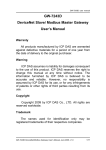
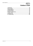
Kramer Electronics, Ltd.
USER MANUAL
Model:
840
DVI Pattern Generator
Contents
Contents
1
2
3
4
5
Introduction
Getting Started
Overview
Your 840 DVI Pattern Generator
Using Your 840 DVI Pattern Generator
Connecting Your 840 DVI Pattern Generator
Operating Your 840 DVI Pattern Generator
Interpreting Each Pattern Number Definition
4
5
6
6
Technical Specifications
7
5.1
5.2
5.3
1
1
1
2
4
Figures
Figure 1: 840 DVI Pattern Generator
Figure 2: Connecting the 840 DVI Pattern Generator
2
4
Tables
Table 1: 840 DVI Pattern Generator Features
Table 2: Selecting the DVI Output Resolutions
Table 3: Pattern Number Definitions
Table 4: Technical specifications of the 840 DVI Pattern Generator
3
3
6
7
i
Introduction
1
Introduction
Welcome to Kramer Electronics (since 1981): a world of unique, creative and
affordable solutions to the infinite range of problems that confront the video,
audio and presentation professional on a daily basis. In recent years, we have
redesigned and upgraded most of our line, making the best even better! Our
350-plus different models now appear in 8 Groups1, which are clearly defined
by function. Congratulations on purchasing your Kramer DigiTOOLS® 840
DVI2 Pattern Generator. It is ideal for the testing and adjusting of flat panel
LCD displays, projectors, plasmas and DVI cables, as well as for testing the
refresh rates of LCD displays by using the motion patterns. The package
includes the following items:
840 DVI Pattern Generator
Power supply3
This user manual4 and the Kramer concise product catalog/CD
2
Getting Started
We recommend that you:
Unpack the equipment carefully and save the original box and packaging
materials for possible future shipment
Review the contents of this user manual
Use Kramer high performance high resolution cables5
3
Overview
The 840 is a high quality DVI-D pattern Generator (VESA compatible) with
32 preset patterns that supports DVI output resolutions: SVGA (800x600),
XGA (1024x768), SXGA (1280x1024), 1400x1050, UXGA (1600x1200),
852x480, 1280x720, 1366x768, 960x540, 720x480, 1920x1080, and
1920x540. All resolutions are @ 60Hz.
1 GROUP 1: Distribution Amplifiers; GROUP 2: Video and Audio Switchers, Matrix Switchers and Controllers; GROUP 3:
Video, Audio, VGA/XGA Processors; GROUP 4: Interfaces and Sync Processors; GROUP 5: Twisted Pair Interfaces;
GROUP 6: Accessories and Rack Adapters; GROUP 7: Scan Converters and Scalers; and GROUP 8: Cables and Connectors
2 Digital Visual Interface was designed to provide the industry with a single, universal digital interface (primarily to provide a
digital connection between a PC and a display device). It is now considered the industry standard digital graphics interface
3 As an option, you can purchase the Kramer VA-50P 6 Port Universal 12-Volt Power Supply, enabling you to supply power
to up to 6 Kramer devices that require 12VDC
4 Download up-to-date Kramer user manuals from the Internet at this URL: http://www.kramerelectronics.com/manuals.html
5 The complete list of Kramer cables is on our Web site at http://www.kramerelectronics.com (click “Cables and Connectors”
in the Products section)
1
Your 840 DVI Pattern Generator
In particular, the 840 includes:
A DVI-D output
Seven control buttons: SVGA, XGA, SXGA, UXGA, Wide (On),
PATTERN – and PATTERN +
A 7-segment display that indicates the pattern number
An on board EERROM that saves the last setting used
Note that only the digital signal (DVI-D) is available on the DVI connector.
To achieve the best performance:
Connect only good quality connection cables, thus avoiding interference,
deterioration in signal quality due to poor matching, and elevated noise levels
(often associated with low quality cables)
Avoid interference from neighboring electrical appliances that may
adversely influence signal quality and position your Kramer 840 away from
moisture, excessive sunlight and dust
4
Your 840 DVI Pattern Generator
Figure 1 and Table 1 define the 840 DVI Pattern Generator (Table 2
summarizes how to select each DVI Output Resolution):
Figure 1: 840 DVI Pattern Generator
2
KRAMER: SIMPLE CREATIVE TECHNOLOGY
Your 840 DVI Pattern Generator
Table 1: 840 DVI Pattern Generator Features
#
Feature
Function
1
2
12V DC
OUTPUT DVI
Connector
1
SVGA Button
+12V DC connector for powering the unit
Connect to the DVI acceptor
3
Selects SVGA (800x600) when pressed. Selects 852x480 when pressed
together with the Wide (On) button. Selects 720x480 when pressed together
with the XGA button and the Wide (On) button
1
4 XGA Button
Selects XGA (1024x768) when pressed. Selects 1280x720 when pressed
together with the Wide (On) button. Selects 720x480 when pressed together
with the SVGA button and the Wide (On) button. Selects 1920x1080 when
pressed together with the SXGA button and the Wide (On) button
1
5 SXGA Button
Selects SXGA (1280x1024) when pressed. Selects 1400x1050 when pressed
together with the UXGA button. Selects 1366x768 when pressed together with
the Wide (On) button. Selects 1920x1080 when pressed together with the
XGA button and the Wide (On) button. Selects 1920x540 when pressed
together with the UXGA button and the Wide (On) button
6 UXGA Button1
Selects UXGA (1600x1200) when pressed. Selects 1400x1050 when pressed
together with the SXGA button. Selects 960x540 when pressed together with
the Wide (On) button. Selects 1920x540 when pressed together with the
SXGA button and the Wide (On) button
1
7 Wide (On) Button
Displays a wide image and provides 7 extra resolutions when pressed together
with one or two of these buttons: SVGA, XGA, SXGA and/or UXGA
8 PATTERN – Button Goes back to the previous pattern number
9 PATTERN + Button Advances to the next pattern number
10 PATTERN NUMBER Shows the pattern number (from 00 to 31)
7-segment Display
11 ON LED
Illuminates when receiving power
Table 2: Selecting the DVI Output Resolutions
To select:
SVGA
SVGA
Press:
XGA
XGA
SXGA
SXGA
1400x1050
SXGA+ UXGA
UXGA
UXGA
852x480
SVGA + Wide (On)
1280x720
XGA + Wide (On)
1366x768
SXGA + Wide (On)
960x540
UXGA + Wide (On)
720x480
SVGA + XGA + Wide (On)
1920x1080
XGA + SXGA + Wide (On)
1920x540
SXGA + UXGA + Wide (On)
1 Illuminates when pressed
3
Using Your 840 DVI Pattern Generator
5
Using Your 840 DVI Pattern Generator
This section describes how to:
Connect the 840 DVI Pattern Generator (see section 5.1)
Operate the 840 DVI Pattern Generator (see section 5.2)
Interpret each Pattern Number Definition (see section 5.3)
5.1 Connecting Your 840 DVI Pattern Generator
To connect the 840 DVI Pattern Generator, do the following1:
1. Connect the OUTPUT connector to a DVI acceptor, for example, a flat
panel LCD display (as Figure 2 illustrates), or a projector or plasma
screen.
2. Connect the 12V DC power adapter (wall transformer) to the 12V DC
socket and connect the transformer to the mains electricity.
Figure 2: Connecting the 840 DVI Pattern Generator
1 Switch OFF the power on the DVI acceptor before connecting it to your 840. After connecting your 840, switch on its
power and then switch on the power on the DVI acceptor
4
KRAMER: SIMPLE CREATIVE TECHNOLOGY
Using Your 840 DVI Pattern Generator
5.2 Operating Your 840 DVI Pattern Generator
Several patterns (see Table 3) are programmed into the 840 DVI Pattern
Generator, in order to assess various aspects in the flat panel LCD display,
projector, Plasma screen or cable. For example, the 840 tests a:
Flat panel LCD display1 by testing if all the pixels illuminate with the
correct amounts of light, linearity, and high frequency response
Projector, verifying that the colors are as required, tuning the size and
focus of the picture
DVI cable, checking the quality2 of the colors, both separately and together
Plasma screen, to check the black level of the plasma monitor (use
PATTERN 00 to generate the black screen)
To operate the 840 DVI Pattern Generator, do the following:
1. Press the appropriate PATTERN button (PATTERN + to display the next
pattern or PATTERN – to display the previous pattern) to generate the
required pattern. The PATTERN NUMBER 7-segment Display shows the
selected pattern number.
2. Observe the output on your flat panel LCD display, projector or plasma
screen.
1 Which is built on a matrix of pixels, each pixel consisting of three components: R, G and B
2 For example, a fuzzy red color in the picture indicates a problem with the red wire
5
Using Your 840 DVI Pattern Generator
5.3 Interpreting Each Pattern Number Definition
Table 3 describes each of the 32 different Patterns:
Table 3: Pattern Number Definitions
DEFINITION
Black screen
01
75% saturated color bar
02
100% saturated color bar
03
Grayscale bar
04
05
Red screen
Green screen
06
Blue screen
07
Yellow screen
08
Cyan screen
09
Magenta screen
10
White screen
11
Gray screen
12
Red, green, blue ramps
13
White crosshatch on black background
14
Red crosshatch on green background
15
16
Red crosshatch on blue background
White squares
17
White dots
18
Active picture border
19
Centered round target and active picture border
Moving vertical line
Moving horizontal line
22
Aperture moving over colored background
24
Motion
20
21
23
Aperture moving over color bar background
Moving red ramp
Moving green ramp
26
27
Moving blue ramp
Bounce
29
30
31
Static
25
28
6
Static
PATTERN NUMBER
00
Multiburst
0/100 Vertical Split
0/100 Horizontal Split
Chess board
KRAMER: SIMPLE CREATIVE TECHNOLOGY
Technical Specifications
6
Technical Specifications
Table 4 includes the technical specifications:
1
Table 4: Technical specifications of the 840 DVI Pattern Generator
OUTPUT:
DVI OUTPUT
RESOLUTIONS:
CONTROLS:
POWER SOURCE:
DIMENSIONS:
WEIGHT:
ACCESSORIES:
2
1 DVI , 1.2Vpp on a DVI Molex 24pin female connector; DDC signal 5Vpp (TTL)
SVGA (800x600), XGA (1024x768), SXGA (1280x1024), 1400x1050, UXGA
(1600x1200), 852x480, 1280x720, 1366x768, 960x540, 720x480, 1920x1080,
and 1920x540. All resolutions @ 60Hz
Control buttons: PATTERN +, PATTERN –, UXGA, SXGA, XGA, SVGA, Wide (On)
12 VDC, 150mA
12cm x 7.5cm x 2.5cm (4.7" x 0.98" x 2.95"), W, D, H
0.3kg. (0.66lbs.)
Power supply, mounting bracket
1 Specifications are subject to change without notice
2 On a DVI-I connector. Note that only the digital signal (DVI-D) is available on the DVI connector
7
LIMITED WARRANTY
Kramer Electronics (hereafter Kramer) warrants this product free from defects in material and workmanship under the
following terms.
HOW LONG IS THE WARRANTY
Labor and parts are warranted for three years from the date of the first customer purchase.
WHO IS PROTECTED?
Only the first purchase customer may enforce this warranty.
WHAT IS COVERED AND WHAT IS NOT COVERED
Except as below, this warranty covers all defects in material or workmanship in this product. The following are not covered
by the warranty:
1.
2.
3.
Any product which is not distributed by Kramer, or which is not purchased from an authorized Kramer dealer. If you are
uncertain as to whether a dealer is authorized, please contact Kramer at one of the agents listed in the web site
www.kramerelectronics.com.
Any product, on which the serial number has been defaced, modified or removed.
Damage, deterioration or malfunction resulting from:
i)
Accident, misuse, abuse, neglect, fire, water, lightning or other acts of nature
ii)
Product modification, or failure to follow instructions supplied with the product
iii)
Repair or attempted repair by anyone not authorized by Kramer
iv)
Any shipment of the product (claims must be presented to the carrier)
v)
Removal or installation of the product
vi)
Any other cause, which does not relate to a product defect
vii)
Cartons, equipment enclosures, cables or accessories used in conjunction with the product
WHAT WE WILL PAY FOR AND WHAT WE WILL NOT PAY FOR
We will pay labor and material expenses for covered items. We will not pay for the following:
1.
2.
3.
Removal or installations charges.
Costs of initial technical adjustments (set-up), including adjustment of user controls or programming. These costs are the
responsibility of the Kramer dealer from whom the product was purchased.
Shipping charges.
HOW YOU CAN GET WARRANTY SERVICE
1.
2.
3.
To obtain service on you product, you must take or ship it prepaid to any authorized Kramer service center.
Whenever warranty service is required, the original dated invoice (or a copy) must be presented as proof of warranty coverage,
and should be included in any shipment of the product. Please also include in any mailing a contact name, company, address, and
a description of the problem(s).
For the name of the nearest Kramer authorized service center, consult your authorized dealer.
LIMITATION OF IMPLIED WARRANTIES
All implied warranties, including warranties of merchantability and fitness for a particular purpose, are limited in duration to
the length of this warranty.
EXCLUSION OF DAMAGES
The liability of Kramer for any effective products is limited to the repair or replacement of the product at our option. Kramer
shall not be liable for:
1.
2.
Damage to other property caused by defects in this product, damages based upon inconvenience, loss of use of the product, loss
of time, commercial loss; or:
Any other damages, whether incidental, consequential or otherwise. Some countries may not allow limitations on how long an
implied warranty lasts and/or do not allow the exclusion or limitation of incidental or consequential damages, so the above
limitations and exclusions may not apply to you.
This warranty gives you specific legal rights, and you may also have other rights, which vary from place to place.
NOTE: All products returned to Kramer for service must have prior approval. This may be obtained from your dealer.
This equipment has been tested to determine compliance with the requirements of:
EN-50081:
"Electromagnetic compatibility (EMC);
generic emission standard.
Part 1: Residential, commercial and light industry"
EN-50082:
"Electromagnetic compatibility (EMC) generic immunity standard.
Part 1: Residential, commercial and light industry environment".
CFR-47:
FCC Rules and Regulations:
Part 15: “Radio frequency devices
Subpart B – Unintentional radiators”
CAUTION!
Servicing the machines can only be done by an authorized Kramer technician. Any user who makes changes or modifications to
the unit without the expressed approval of the manufacturer will void user authority to operate the equipment.
Use the supplied DC power supply to feed power to the machine.
Please use recommended interconnection cables to connect the machine to other components.
8
KRAMER: SIMPLE CREATIVE TECHNOLOGY
For the latest information on our products and a list of Kramer
distributors, visit our Web site: www.kramerelectronics.com.
Updates to this user manual may be found at
http://www.kramerelectronics.com/manuals.html.
We welcome your questions, comments and feedback.
Kramer Electronics, Ltd.
Web site: www.kramerelectronics.com
E-mail: [email protected]
P/N: 2900-000840 REV 2