1
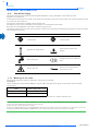
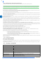
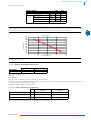
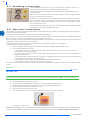
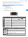
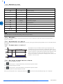
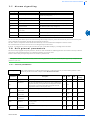
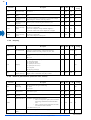
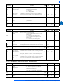
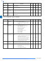
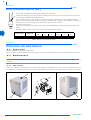
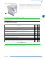
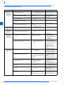
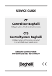
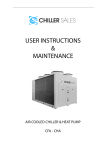
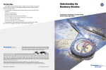
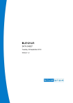
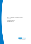
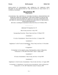
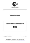
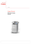
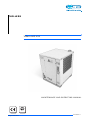
CHILLERS
TAEevo M05-M10
M A I N T E N A N C E A N D O P E RA T I N G M A N U A L
Original instructions
38178800511
MAINTENANCE AND OPERATING MANUAL
INDEX
INDEX ............................................................................................................................................................................1
GENERAL INFORMATION .............................................................................................................................................2
1.1
Terminology..................................................................................................... 2
SAFETY..........................................................................................................................................................................3
2.1
General............................................................................................................. 3
2.2
General precautions ......................................................................................... 3
2.3
Safety schedule ................................................................................................ 4
TECHNICAL DATA.........................................................................................................................................................6
3.1
Data plate and meaning of abbreviations......................................................... 6
DESCRIPTION ................................................................................................................................................................8
4.1
Operating principle .......................................................................................... 8
4.2
Overall dimensions .......................................................................................... 8
4.3
Minimum distances from walls........................................................................ 8
4.4
Water and refrigerant circuits .......................................................................... 8
4.5
Electrical circuit ............................................................................................... 9
INSTALLATION ..............................................................................................................................................................9
5.1
Inspection......................................................................................................... 9
5.2
Positioning ....................................................................................................... 9
5.3
Antifreeze protection ....................................................................................... 9
5.4
Plumbing connections.................................................................................... 10
5.5
Electrical connections .................................................................................... 10
START UP ....................................................................................................................................................................10
ELECTRONIC CONTROL BOARD .................................................................................................................................11
7.1
Introduction.................................................................................................... 11
7.2
User interface-key functions .......................................................................... 11
7.3
Display ........................................................................................................... 12
7.4
Automatic re-start .......................................................................................... 12
7.5
Compressor control........................................................................................ 12
7.6
Storage temperature alarm ............................................................................. 12
7.7
Alarms signalling ........................................................................................... 13
7.8
Unit general parameters ................................................................................. 13
7.9
Digital input alarms ...................................................................................... 16
7.10 Other parameters........................................................................................... 17
7.11 “i1F” parameter digital input ......................................................................... 17
HIGH PRESSURE SWITCH (HP) ..................................................................................................................................18
OPERATION AND MAINTENANCE ...............................................................................................................................18
9.1
Operation ....................................................................................................... 18
9.2
Maintenance................................................................................................... 18
TROUBLE SHOOTING ..................................................................................................................................................20
TAEevo M05-M10
The data inside this manual are not binding and they can be modified by the manufacturer without notice. All rights reserved.
1
2
CHAPTER 1
GENERAL INFORMATION
1.1
Terminology
The machines described in this manual are called “WATER CHILLERS” or simply “CHILLERS”. These chillers have been
designed to cool a liquid flow.
In most applications, the liquid to be cooled is water and the term “WATER” will be used even if the liquid to be cooled is different from water
(e.g. a mixture of water and glycol).
The liquid to be cooled must be compatible with the materials used.
This manual is written for those responsible for the installation, use and maintenance of the chiller.
Here below the term “PRESSURE” will be used to indicate the gauge pressure.
The following symbols are shown on the stickers on the unit as well as on the overall dimension drawing and refrigeration circuits in this manual.
Their meaning is the following:
SYMBOL
DESCRIPTION
SYMBOL
DESCRIPTION
Unit water inlet
Unit water outlet
Indications for lifting the unit
Water drainage point from the
machine
Water filling point
Cooling air flow (for air-condensed
units)
Electric shock risk
Direction of the refrigerant fluid
flow and water circuit
Table 1 SYMBOLS
1.1.1
Meaning of the code
The chillers described in this manual are defined by a code with a precise meaning.
TAEevo Mxx:
Chiller with Tank, Air-cooled condenser, HErmetic compressor, M= single-phase power supply. The table below shows the nominal
cooling capacity:
Model
Nominal cooling capacity (*) [W]
TAEevo M05
2500
TAEevo M10
4400
(*) Referred to the following operating conditions: water inlet 20°C, water outlet 15°C, ambient temperature 25°C.
ATTENTION
This manual provides the user, installer and maintenance technician with all the technical information required for installation, operation and
carrying out routine maintenance operations to ensure long life.
If spare parts are required, this must be original.
Requests for SPARE PARTS and for any INFORMATION concerning the unit must be sent to the distributor or to the nearest service centre,
providing the MODEL and MACHINE NUMBER shown on the machine data plate and on the first page of this manual.
TAEevo M05-M10
The data inside this manual are not binding and they can be modified by the manufacturer without notice. All rights reserved.
MAINTENANCE AND OPERATING MANUAL
CHAPTER 2
SAFETY
This machinery was designed to be safe in the use for which it was planned provided that it is installed, started up and maintained in accordance
with the instructions contained in this manual.
The manual must therefore be studied by all those who want to install, use or maintain the machinery.
The machine contains electrical components which operate at the line voltage, and also moving parts as fans and/or pumps. It must therefore be
isolated from the electricity supply network before being opened.
All maintenance operations which require access to the machinery must be carried out by expert or appropriately trained persons who have a
perfect knowledge of the necessary precautions.
2.1
General
When handling or maintaining the unit and all auxiliary equipment, the personnel must operate with care observing all instructions concerning
health and safety at installation site.
Most accidents which occur during the operation and maintenance of the machinery are a result of failure to observe basic safety rules or
precautions. An accident can often be avoided by recognising a situation that is potentially hazardous.
The user should make sure that all personnel concerned with operation and maintenance of the unit and all auxiliary equipment have read and
understood all warnings, cautions, prohibitions and notes written in this manual as well as on the unit.
Improper operation or maintenance of the unit and auxiliary equipment could be dangerous and result in an accident causing injury or death.
Do not operate the unit and auxiliary equipment until the instructions in the Operating section of this manual are understood by all personnel
concerned. Do not carry out any servicing, repair or maintenance work on the unit and auxiliary equipment until the instructions in the relevant
sections of this manual are clearly understood by all personnel concerned.
We cannot anticipate every possible circumstance which might represent a potential hazard. The warnings in this manual are therefore not allinclusive. If the user employs an operating procedure, an item of equipment or a method of working which is not specifically recommended, he
must ensure that the unit and auxiliary equipment will not be damaged or made unsafe and that there is no risk to persons or property.
ATTENTION
The hot / cold water produced by MTA units cannot be used directly for domestic hygiene or food applications. In the case
of such applications, the installer is responsible for fitting an intermediate exchanger.
If the intermediate exchanger is not fitted, the installer should affix a notice stating "non-drinking water".
2.2
General precautions
2.2.1
Liquids to be cooled
The liquids to be cooled must be compatible with the materials used.
These can be water or mixtures of water and glycol, for example. In case of distilled or demineralised water, check the compatibility with
materials.
It is advisable to work with pH between 7 and 8. If using chemical additives consult your supplier for more information concerning compatibility
with materials in contact with the process fluid of the chiller.
The liquids to be cooled must not be flammable.
ATTENTION
If the liquids to be cooled contains dangerous substances (e.g. ethylene glycol) it is very important to collect any liquid which leaks because it
could cause damages to the ambient. Furthermore, when the chiller is no longer used, dangerous liquids must be disposed of by firms specialised
and authorised for treating them.
2.2.2
Lifting and carriage precautions
Handling the chillers using fork-lift trucks must be carried out in accordance with the drawings in annexes: TOC xxx.
2.2.3
Installation precautions
For the connection to the electrical net see chapter “Installation” .
2.2.4
P r e c a u t i o n s d u r i n g o p e ra t i o n
Operation must be carried out by competent personnel under a qualified supervisor.
All the cooled water or cooling water piping must be
painted or clearly marked in accordance with local safety regulations in the place of installation.
ATTENTION
Never remove or tamper with the safety devices, guards or insulation materials fitted to the unit or auxiliary equipment.
All electrical connections must comply with local codes. The unit and auxiliary equipment must be earthen and protected by fuses against shortcircuits and overloading.
ATTENTION
Do not open any electrical panels or cabinets while voltage.
TAEevo M05-M10
The data inside this manual are not binding and they can be modified by the manufacturer without notice. All rights reserved.
3
4
2.2.5
M a i n t e n a n c e a n d r e p a i r p re c a u t i o n s
Maintenance, overhaul and repair work must be carried out by competent personnel under a qualified supervisor.
ATTENTION
When disposing of parts and waste material of any kind make sure that there is no pollution of any drain or natural water-course and that no
burning of waste takes place which could cause pollution of the air. Protect the environment by using only approved methods of disposal.
If replacement parts are needed use only original spares.
Keep a written record of all maintenance and repair work carried out on the unit and auxiliary equipment. The frequency and the nature of the
work required over a period can reveal adverse operating conditions which should be corrected.
Use only refrigerant gas specified on the plate of the unit.
Make sure that all instructions concerning operation and maintenance are strictly followed and that the complete unit, with all accessories and
safety devices, is kept in good working order.
The accuracy of temperature/pressure measuring devices must be checked regularly; renew measuring devices when the measurement tolerance
is outside the specified range of values.
Keep the machine clean at all times. Protect components and exposed openings by covering them, for example, with clean cloth or tape during
maintenance and repair work.
Do not weld or carry out any operation which produces heat near a system which contains oil or flammable liquids. The systems which may
contain oil or flammable liquids must be completely drained and cleaned (with steam, for example), before carrying out these operations. Never
weld, nor modify in any way, a vessel which may be put under pressure.
To prevent an increase in working temperature and pressure, inspect and clean heat transfer surfaces (i.e. condenser fins) regularly. For every
unit establish a suitable time schedule for cleaning operations.
Avoid damage to safety valves and other pressure relief devices. Avoid plugging by paint, oil or dirt accumulation.
Precautions must be taken when carrying out welding or any repair operation which generates heat, flames or sparks. The adjacent components
must always be screened with non-flammable material and if the operation is to be carried out near any part of the lubrication system, or close to
a component which may contain oil, the system must first be thoroughly purged, preferably by steam cleaning.
Never use a light source with an open flame to inspect any part of the machine.
Before dismantling any part of the unit ensure that all heavy movable parts are secured.
When a repair has been completed, make sure no tools, loose parts or rags are left in, or on the machine.
All guards must be reinstated after carrying out repair or maintenance work.
Do not use flammable liquid to clean any component during operation. If chlorinated hydrocarbon non-flammable fluids are used for
cleaning, safety precautions must be taken against any toxic vapours which may be released.
Before removing any panels or dismantling any part of the unit, carry out the following operations:
•
Isolate the chiller unit from the main electrical power supply by disconnecting the cable from the electrical power source.
Lock the isolator in the “OFF” position with a lock.
• Attach a warning label to the main isolator switch conveying: “WORK IN PROGRESS - DON NOT APPLY VOLTAGE”. Do
not switch on electrical power or attempt to start the unit if a warning label is attached.
Coloured tracers can be used in service-maintenance operations.
Inspect all refrigerant circuit joints including connectors, flanges, and more generally all critical points (open joints) in order to prevent possible
leakage of refrigerant gas.
2.2.6
Refrigerant gases
R407C is used as refrigerant in these units.
Never attempt to mix refrigerant gases.
To clean out a very heavily contaminated refrigerant system, e.g. after a refrigerant compressor burnout, a qualified refrigeration engineer must
be consulted to carry out the task.
The manufacturer's instructions and local safety regulations should always be observed when handling and storing high pressure gas cylinders.
2.3
Safety schedule
R407C
Denomination:
23% Difluoromethane (R32); 25% Pentafluoroethane (R125); 52% R134a
INDICATION OF THE DANGERS
Major dangers:
Asphyxia
Specific dangers:
Rapid evaporation can cause freezing
General information:
Do not give anything to unconscious persons
Inhalation:
Take the person outdoors. Use oxygen or artificial respiration if necessary. Do not administer
adrenaline or similar substances
FIRST AID MEASURES
Contact with the eyes:
Thoroughly wash with plenty of water for at least 15 minutes and call a doctor
Contact with the skin:
Wash immediately with plenty of water.
Remove contaminated clothing immediately
TAEevo M05-M10
The data inside this manual are not binding and they can be modified by the manufacturer without notice. All rights reserved.
MAINTENANCE AND OPERATING MANUAL
R407C
FIRE-FIGHTING MEASURES
Means of extinction:
Any means
Specific dangers:
Pressure increase
Specific methods:
Cool the containers with water sprays
MEASURES IN THE EVENT OF ACCIDENTAL LEAKAGE
Individual precautions:
Evacuate personnel to safe areas. Provide adequate ventilation. Use means of personal protection
Environmental precautions:
Evaporates
Cleaning methods:
Evaporates
HANDLING AND STORAGE
Handling
technical measures/ precautions:
Ensure sufficient air change and/or extraction in the work areas
recommendations for safe use:
Do not inhale vapours or aerosols
Storage:
Close properly and store in a cool, dry well-ventilated place. Store in its original containers.
Incompatible products: explosives, flammable materials, organic peroxide
Control parameters:
AEL (8-h e 12-h TWA) = 1000 ml/m3 for each of the three components
Respiratory protection:
For rescue and maintenance work in tanks, use autonomous breathing apparatus. The vapours are
heavier than air and can cause suffocation, reducing the oxygen available for breathing
Protection of the eyes:
Safety goggles
Protection of the hands:
Rubber gloves
Hygiene measures:
Do not smoke
CONTROL OF EXPOSURE/INDIVIDUAL PROTECTION
PHYSICAL AND CHEMICAL PROPERTIES
Colour:
Colourless
Odour:
Similar to ether
Boiling point:
-43.9°C / -47.0°F at atm. press.
Flammability point:
Non flammable
Relative density:
1.138 kg/l at 25°C
Solubility in water:
Negligible
Stability:
No reactivity if used with the relative instructions
Materials to avoid:
Alkaline metal, earthy alkaline metals, granulated metals salts, Al, Zn, Be, etc. in powder.
Hazardous decomposition products:
Halogen acids, traces of carbonyl halides
Acute toxicity:
(R32) LC50/inhalation/4 hours/lab. rats >760 ml/l
(R125) LC50/inhalation/4 hours/lab. rats >3480 mg/l
(R134a) ALC/inhalation/4 hours/lab. rats = 567 ml/l
Local effects:
Concentrations substantially above the TLV can cause narcotic effects. Inhalation of products in
decomposition can lead to respiratory difficulty (pulmonary oedema)
Long-term toxicity:
Has not shown any cancerogenic, teratogenic or mutagenic effects in experiments on animals
STABILITY AND REACTIVITY
TOXICOLOGICAL INFORMATION
ECOLOGICAL INFORMATION
Global warming potential HGWP
(R11=1):
R125: 0.84 - R134a: 0.28
Ozone depletion potential ODP
(R11=1):
0
Considerations on disposal:
Usable with reconditioning
TAEevo M05-M10
The data inside this manual are not binding and they can be modified by the manufacturer without notice. All rights reserved.
5
6
CHAPTER 3
TECHNICAL DATA
3.1
Data plate and meaning of abbreviations
The main technical data are given on the machine data plate:
MODEL and CODE
The model number and the code identify the size of the unit (see Chapter 1 “General information“)
and the type of construction.
MANUAL
This is the code number of the manual.
SERIAL NUMBER
This is the construction number of the unit.
MANUFACTURING YEAR
This is the year of the final test of the unit.
VOLTAGE/PHASE/
FREQUENCY
Electric alimentation characteristics.
MAX. CONSUMPTION
(Imax)
This is electrical current consumed by the unit during the limit working conditions (refrigerant
condensing temperature is 65°C = 149°F; refrigerant evaporating temperature is 10°C = 50°F).
INSTALLED POWER
(Pmax)
It is the power absorbed by the unit during the limit working conditions (refrigerant condensing
temperature is 65°C = 149°F; refrigerant evaporating temperature is 10°C = 50°F).
PROTECTION
As defined by the EN 60529 European standard.
REFRIGERANT
This is the refrigerant fluid in the unit.
REFRIGERANT QUANTITY
This is the quantity of refrigerant fluid contained in the unit.
MAX. COOLING PRESSURE
This is the design pressure of the refrigeration circuit.
MAX. COOLING
TEMPERATURE
This is the design temperature of the refrigeration circuit.
USER CIRCUIT FLUID
Fluid cooled by the unit (normally water).
MAX. OPERATING
PRESSURE
Max. design pressure of the user circuit.
MAX. TEMPERATURE
Design temperature of the user circuit; this should not be confused with the maximum working
temperature which is established when the offer is made.
CONDENSER COOLING
FLUID
Fluid used by the unit to cool the condenser (this data is not present if the unit is air cooled
condensed).
MAX. OPERATING
PRESSURE
Max. design pressure of the condenser cooling circuit (this data is not present if the unit is air cooled
condensed).
MAX. TEMPERATURE
Max. design temperature of the condenser cooling circuit (this data is not present if the unit is air
cooled condensed).
SOUND PRESSURE LEVEL
Sound pressure level in free field in hemispheric irradiation conditions (open field) at a distance of 1
m from the unit, condenser side, and at a distance of 1.6 m from the ground.
AMBIENT TEMPERATURE
Min. and max. cooling air temperature value.
WEIGHT
This is the approximate weight of the unit before packing.
Table 2 DATA
PLATE AND MEANING OF ABBREVIATIONS
On the wiring diagram you will find the following abbreviations (see the first column in the table above):
IMAX
max. electric current
PMAX
max. power
ILR
electric current with rotor stopped
ATTENTION
The performance of the refrigerant depends principally on the flow rate and temperature of the cooled water and on the temperature of the
condenser cooling fluid (ambient temperature or water input temperature respectively, depending on whether the condenser is air or watercooled). These data are defined in the offer and it is to these that reference should be made.
TAEevo M05-M10
The data inside this manual are not binding and they can be modified by the manufacturer without notice. All rights reserved.
MAINTENANCE AND OPERATING MANUAL
Other data for standard units:
TAEevo MODEL
M05
Tank capacity
P3 NoFe
M10
[litres]
25
25
water flow rate
[l/min]
8/40
8/40
pump head
[bar]
4/0
4/0
nominal power
[kW]
0,33
0,33
type
peripheric
Table 3 PERFORMANCES
NOTE
Standard pumps are of peripheral type, so the pump heads indicated in the table are respectively at no flow and at max. flow. It is possible for
the pump installed to be different from the standard one. In this case reference should be made to the data in the offer.
PUMP HEADS
PRESSURE mca
50
45
40
35
30
25
20
15
10
5
0
0
10
20
FLOW RATE l/min
30
40
NOTE
The pump must never run dry.
3.1.1
Sound Level Measurements
Lp dB(A) *
Lw dB(A) **
TAEevo M05
63,3
76,3
TAEevo M10
63,3
76,3
* at distance of 1 metre (3,2 FT)
** global
Test conditions
Noise levels refer to operation of the unit at full load in nominal conditions.
Sound pressure level in hemispherical irradiation conditions at a distance of 1 m (3,2 FT) from the condenser side of the unit and height of 1.6 m
(5,2 FT) from the ground. Values tolerance ± 2 dB.
Sound power level: in compliance with ISO 3744
3.1.2
Limit operating conditions
Minimum
Maximum
Ambient air temperature
°C
5
40
Evaporator water inlet temperature
°C
5
35
Evaporator water outlet temperature
°C
0(1)
30
(1) For temperatures below +5°C use antifreeze solutions (see 5.3 “Antifreeze protection” ).
TAEevo M05-M10
The data inside this manual are not binding and they can be modified by the manufacturer without notice. All rights reserved.
7
8
CHAPTER 4
DESCRIPTION
4.1
Operating principle
All the chillers described in this manual work on the basis of the same principle. A refrigerant circuit cools the exchange surface of an
evaporator through which the liquid to be cooled passes.
The evaporator finds inside the tank.
The refrigerant compressor is controlled by an electronic control unit.
The electronic control unit controls the temperature of the water in the tank to maintain it within preset limits.
Also consult Chapter 7 “Electronic control board“.
4.1.1
Compressor
Hermetic or rotary type, cooled by the aspirated refrigerant and equipped with thermal cutout protection.
The compressor is mounted on anti-vibration supports.
4.1.2
Casing
Built with galvanised panels and painted with epoxy resins.
The panels have no structural function so that they can easily be removed to permit total access to all the components.
4.1.3
Materials in contact with the liquid to be cooled
Stainless steel, copper, brass, plastics.
4.1.4
Condenser and fan
Air cooled condensers are used without steel tubes; in this case it is the fins that form the tube by means of long collars inserted one inside the
other and brazed with copper in a controlled atmosphere oven. The condensing coils are equipped with an axial fan complete with protective
grille. The fan is of the “pressure” type: the air is drawn from the interior of the unit and expelled into the atmosphere, flowing through the
condensing coil along its route.
4.1.5
Evaporator
Consisting of a copper tube in tube exchanger. The water flows in counter-current to the evaporating refrigerant.
4.1.6
Pump
Of peripheric type, body in brass/bronze, impeller in brass, shaft in stainless steel.
ATTENTION
If the pump would clump, follow the instructions in paragraph 9.2.2 “Unjamming the pump”
NOTE
The pump must never run dry.
4.1.7
Accumulation tank
A
In these units are used stainless steel accumulation tanks.
TAEevo M are furnished with cylindrical tank, finding in vertical position over the unit’s base.
The tanks, hermetically closed, contain the evaporator.
The hydraulic circuit is of atmospherical type and by a plastic receptacle with a capacity of about 1,5 litres,
complete with a plug (A), it is possible to fill the unit.
B
4.2
This receptacle is fixed to the machine casing in which there is a slot (B) for inspecting the water level and a
hole which permits access to the filling plug from the outside.
Overall dimensions
See enclosures RED xxx
4.3
Minimum distances from walls
See enclosures RED xxx
4.4
Water and refrigerant circuits
See enclosures REF xxx
4.4.1
Water circuit
The water flowing through the evaporator pipes cools and flows into the tank.
Then the water is sucked by a peripheric pump which sends it directly to the user.
The pump delivery is connected to the evaporator by a by-pass pipe which guarantees a minimum water flow through the pump should a pipe at
any point of the hydraulic circuit be closed by mistake.
TAEevo M05-M10
The data inside this manual are not binding and they can be modified by the manufacturer without notice. All rights reserved.
MAINTENANCE AND OPERATING MANUAL
A pressure gauge is connected to the pump output. It indicates the outlet water pressure of the plant.
4.4.2
R e f ri g e ra n t c i r c u i t
The refrigerant is pumped by the refrigerant compressor to the condenser. The condenser is a heat exchanger and is cooled by an air flow
produced by a fan.
After the condenser, the refrigerant liquid passes through a drying filter and a laminating element (capillary tube).
The refrigerant then enters the evaporator’s circuit in which it flows in counter-current with respect to the water to be cooled.
When it exits the evaporator, the refrigerant is again sucked by the compressor and the cycle repeats itself.
The refrigerant circuit is also furnished with a high pressure switch (HP) of manual reset type.
4.5
Electrical circuit
See the enclosed electrical diagrams.
CHAPTER 5
INSTALLATION
ATTENTION
Before carrying out the installation or operating on this machine, ensure that all the personnel has read and understood the “Safety” chapter
in this manual.
5.1
Inspection
Immediately after uncrating, inspect the unit.
5.2
Positioning
1. The chiller must be installed indoors only.
2. The room must be well ventilated. In some cases it may be necessary to install fans or extractors to limit the temperature of the
room.
3. The ambient air must be clean and not contain flammable gas or solvents. The minimum and maximum working ambient
temperatures are specified on the unit data plate. In extreme temperature conditions, the protection devices may trip.
4. The machine can be positioned on any flat surface capable of supporting its weight.
5. Leave at least one metre in front of the unit to permit access during service operations (see chapter 4.2 “Overall dimensions” ).
6. Do not obstruct or disturb the condenser's flow of cooling air. Position the chiller in such a way that the cooling air cannot
recirculate in the intake grilles. Ensure that the chiller is not subject to warm air from the cooling systems of other machines.
5.3
Antifreeze protection
Even if the minimum working ambient temperature is above 0°C it is possible for the chiller - during stoppages in the cold seasons - to find
itself in an environment with a temperature below 0°C. In these cases, if the chiller is not emptied, antifreeze (ethylene glycol) must be
added in the following percentages to prevent the formation of ice:
Ambient temperature
up to [°C]
Ethylene Glycol
[% in weight]
0
0
-5
15
-10
25
-15
30
-20
40
According to the outlet temperature of cooled water, it is necessary to add the following antifreeze (ethylene glycol) percentages in order to
avoid freezing:
Water outlet minimum
temperature [°C]
Ethylene Glycol
[% in weight]
0<T
15
TAEevo M05-M10
The data inside this manual are not binding and they can be modified by the manufacturer without notice. All rights reserved.
9
10
5.4
Plumbing connections
It is recommended to insert a filter of “Y” type on the water inlet connection, in order to stop
eventual impurities of water which could cause big damages to the pump.
1.Connect the chiller to the water piping. See the overall dimension drawings for the size and
type of connections.
2.Provide two cocks (inlet and outlet) to by-pass the machine for maintenance purposes without
having to empty the water circuit of the user.
3.Fill the water receptacle by unscrewing the plug of the receptacle and filling the circuit with
water (for example using a hose connected to the cock) until the level in the receptacle is about
half-way up the slot. The filling of tank before starting-up the unit is very important as the pump
can not operate without water.
The receptacle used for filling the circuit acts as an open expansion tank. It is therefore necessary
to pay attention to the volumes and dimensions in play.
5.5
Electrical connections
Check that the power supply voltage and frequency match the requirements of the unit as shown on the unit data plate and they are within the
tolerances given in the wiring diagram.
Ensure that the electrical installation complies with local wiring and safety regulations.
Check that there is a neutral line in the electrical installation and it is earthen in the transformer cabin (TN system in compliance with IEC 364 HD 384 - CEI 64-8) or that this is done by the electricity supply company (TT system).
The electrical supply cable must be connected to the electrical installation and pay attention to connect the neutral wire of the unit (indicated by
the appropriate colour) to the neutral wire of the installation.
The electrical supply cable must be the one supplied with the unit and/or indicated in the electrical wiring diagrams.
At the beginning of the electrical supply cable
1. must be guaranteed a protection against direct contacts with a protection degree of IP2X or IPXXB at least;
2. must be installed protection devices that:
•
•
•
•
For protection
protect against overcurrents, the power supply cable and the cables not protected by the electrical plant of the machine;
(see information in the electrical wiring)
limit the 17 kA peak short circuit current to its own nominal cut-off power when the short circuit current at the operation point is
higher than 10 kA effective;
protect against indirect contacts on the unit, (such as short-circuiting between the phase and protection circuit) by cutting off the
supply automatically (see IEC 364 - HD 384, CEI 64-8);
Use a differential switch (normally with operation nominal differential current of 0.03 A)
protect against phase failures where the electrical supply is three-phase.
circuit dimensions, please refer to the data specified in the wiring diagrams attached (max. absorption, pick-up currents, cables
section).
CHAPTER 6
START UP
ATTENTION
Before starting up or operating these units be sure that all personnel have read and understood the “Safety” section of this manual.
1. Check that the machine's on/off valves are open.
2. Check that the level of the liquid in the receptacle is at about the middle of the graduated scale.
3. Check that the ambient temperature is within the limits indicated on the machine data plate.
4. Check that the main switch is in the OFF position (“O”).
5. Check that the power supply voltage is correct.
6. Turn the machine main switch ON (“I”). The display lights on to indicate the presence of tension.
7. The pump is not ready to start.
If with the first start-up, there is a high ambient temperature and the temperature of the water in the hydraulic circuit is much higher than the
working value (e.g. 25-30°C) this means that the chiller starts up overloaded with the consequence of possible tripping of the compressor
TAEevo M05-M10
The data inside this manual are not binding and they can be modified by the manufacturer without notice. All rights reserved.
MAINTENANCE AND OPERATING MANUAL
protection devices. To reduce this overload, a chiller outlet valve can be gradually (but not totally!) closed to reduce the flow of
water passing through it. Open the valve as the water temperature in the hydraulic circuit reaches the working value.
If the thermal load is lower than that produced by the chiller, the water temperature drops until it reaches the set point.
With operating pump, if the unit is in normal operation, the water should be at mid-slot in the receptacle.
CHAPTER 7
ELECTRONIC CONTROL BOARD
7.1
Introduction
The main function of the electronic control board are:
• complete management of the alarms;
• control of the temperature at evaporator outlet.
The electronic control board allows to control the following devices:
•
•
•
7.2
pump;
compressor;
alarm signalling devices.
User interface-key functions
Key
Action
Function
Pressed once
The set-point will be displayed
Chiller set-point modification, the °C LED flashes, use keys
Pressed for 3 seconds
set-point. To save the parameter press key
to change the
or simply wait 15 sec.
Shows maximum temperature value
In the programming phase scrolls through the parameter codes or increases their value
Pressed once
Shows minimum temperature value
In the programming phase scrolls through parameter codes or decreases their value
Pressed once
Switches device on/off
Pressed once
Pressed once
7.2.1
Starts a defrost cycle (not active function)
Key combinations
Key
+
Function
Lock/ unlock the keypad:
Hold down both keys until the message "POF" is displayed. Repeat the procedure to unlock, the message "Pon" is
displayed
To access the hidden menu:
Open programming mode by holding down the key combination for 3 seconds (access is granted to Pr1
+
parameters);
In programming mode (Pr1) press the key combination for at least 7 seconds: the message "Pr2" is displayed
(access is granted to Pr2 parameters in the hidden menu)
Each parameter can be moved from Pr2 to Pr1 and vice versa.
+
To quit the programming area
TAEevo M05-M10
The data inside this manual are not binding and they can be modified by the manufacturer without notice. All rights reserved.
11
12
7.2.2
M EA N I N G O F L ED s
The table below describes the LED functions:
LED
MODE
MEANING
on
Flashing
on
Flashing
B
Compressor running
Time lag between consecutive compressor starts
Defrost in progress (Not active function)
Dripping in progress (Not active function)
Fans running (Not active function)
on
B
Flashing
on
Temperature alarm
on
Continuous cycle in progress
on
Energy saving in progress (Function not active)
/
on
Unit of measurement
/
Fan start delay in progress
Programming
Flashing
NOTE
(*) the new value set is saved also when quitting without pressing the SET key.
7.3
Display
The display is composed of 3 digits. Temperature detected by probe (-BT1) is displayed with decimal resolution, the field of display is: 50÷110°C (-58÷230°F).
7.4
Automatic re-start
After a loss of power, the unit will re-start automatically if it was ON, observing the selected operating modality, but not if it was OFF before the
loss of power.
7.5
Compressor control
Temper.
The compressor relay is activated to maintain a given temperature value
established by the set-point. Hysteresis Hy is automatically added to the set-
SET+HY
point. If the temperature value increases and reaches the set-point + hysteresis
SET
value, the compressor is started and then stopped when the temperature value
Time
Compr.
activation or deactivation of the output are managed by time by means of the
ON
7.6
returns to the set-point value. If the probe (-BT1) develops a fault, the
parameters “COn” and “COF”.
Storage temperature alarm
To view the minimum temperature reached:
Press
, the message "Lo" is displayed followed by the minimum temperature reached.
To view the maximum temperature reached:
Press
, the message "Hi" is displayed followed by the maximum temperature reached.
To delete the maximum or minimum temperature reached:
When the stored temperature value is displayed, hold down key
for several seconds (the flashing message "rSt" is displayed).
TAEevo M05-M10
The data inside this manual are not binding and they can be modified by the manufacturer without notice. All rights reserved.
MAINTENANCE AND OPERATING MANUAL
7.7
Alarms signalling
Message
Cause
P1
Outputs
Thermostat probe (-BT1) faulty
Compressor output according to parameters “COn” and “COF”
(alarm relay changeover)
P2
Evaporator probe faulty
Defrost by time (function not active)
HA
High temperature alarm
Not modified (alarm relay changeover)
LA
Low temperature alarm
Not modified (function not active, alarm relay changeover)
EA
External alarm
Not modified (alarm relay changeover)
CA
High pressure switch alarm (HP)
Loads off (alarm relay changeover)
(i1F=bAL)
dA
Door open
Loads according to “odC” (alarm relay changeover)
CA
Pressure switch alarm (i1F=PAL)
Loads off (alarm relay changeover)
The “P1” and “P2” probe alarms trip few seconds after the probe develops a fault; they switch off automatically few seconds after the probe
starts to function properly. Before renewing the probe check the connections.
The “HA” and “LA” temperature alarms switch off automatically as soon as the thermostat temperature returns to normal.
The external EA and CA alarms switch off as soon as the digital input is deactivated.
If the I.D. is configured as a pressure switch (i1F=bAL) the reset is performed manually by switching off the instrument.
7.8
Unit general parameters
The unit is factory-equipped with preset parameters, which are values calculated for standard applications. If it becomes necessary to edit the
values of any of the general parameters, we recommend contacting your Service Centre.
Failure to observe this prescription exposes the user and unit to potential risks.
ATTENTION
The manufacturer declines all possible warranty claims concerning performances and safety standards following arbitrary modification of the
parameters by the user.
7.8.1
C o n t r o l p a ra me t e r s
Visible parameters
The visible parameters are set during the design stage. If it becomes necessary to make a hidden parameter visible,
follow the procedure described in chapter 7.2.2 “MEANING OF LEDs”
Parameter
Set
Description
Factory
settings
U.M.
The setting for water temperature at the unit outlet
-50
110
°C
7
Hysteresis
Set-point trip differential. The hysteresis value is added to the
set-point: the relay is energised when the temperature reaches
the set-point + hysteresis value and de-energised when the
temperature returns to the set-point value.
0,1
25
°C
4
-50
SET
°C
0
SET
110
°C
30
-12
12
°C
0
LS
Minimum setpoint value
Establishes the set-point minimum value.
US
Maximum setpoint value
Establishes the set-point maximum value.
Ot
Thermostat probe
calibration
Serves to calibrate the thermostat probe
Evaporator probe
presence
Serves to set the evaporator probe:
n= not present
Y= present.
Evaporator probe
calibration
Serves to calibrate the evaporator probe
OE
Max.
Set-point
Hy
P2P
Min.
Table 4 CONTROL
n
-12
12
°C
0
PARAMETERS
TAEevo M05-M10
The data inside this manual are not binding and they can be modified by the manufacturer without notice. All rights reserved.
13
14
Parameter
Description
Min.
Max.
Factory
settings
U.M.
OdS
Power on outputs
activation delay
At the time of power-on activation of all loads is inhibited for
the time set
0
255
min
0
AC
Anti-hunting
delay
Minimum interval between compressor stop and successive
start
0
50
min
6
CCt
Continuous cycle
duration
To set the continuous cycle duration, to be used for example
when filling the cold store with new products.
0
24 h
°C
0
CCS
Continuous cycle
set-point
This set-point is used during the continuous cycle
-50
150
°C
-5
Compressor On
time with faulty
probe
Time for which the compressor continues to run in the
presence of a probe fault
COn=0 the compressor always remains stopped (*)
(*) If COn=0 and “COF”=0 the compressor is stopped
0
255
min
0
Compressor Off
time with faulty
probe
Time for which the compressor remains stopped in the
presence of a probe fault
COF=0 the compressor is always on
0
255
°C
0
COn
COF
Table 4 CONTROL
7.8.2
PARAMETERS
Display
Parameter
CF
Description
Temperature unit
of measurement
Serves to set the unit of measurement.
If the unit of measurement is changed the following
parameters must be reset: Hy, LS,US, Ot, ALU, ALL
Resolution
Allows the decimal point to be displayed
in=1°C
dE=0,1°C
rES
Lod
Display
Min.
Max.
Factory
settings
U.M.
°C÷°F
°C
dE
Select the probe to be displayed
P1= thermostat probe
P2= evaporator probe
P3= probe (P3 not active)
P1
P4= probe (P4 not active)
Set= set-point
dtr= display percentage
Temperature
display time lag
dLy
7.8.3
As the temperature rises the displayed value increases by 1
degree Celsius or Fahrenheit every dLy minutes.
Description
Type of
defrosting
Serves to choose the type of defrosting
El= heater
in= hot gas
dtE
Defrost End
Temperature
Establishes the evaporator temperature that determines the end
of the defrost cycle.
ldF
Defrost cycles
interval
Establishes the interval between the start of two defrost cycles
Defrost duration
Establishes maximum defrost duration
• P2P= n no evaporator probe (time controlled
defrosting) establishes the defrost duration
time
• P2P= y (defrost end at temperature) becomes
the maximum defrost duration
(*) 0 inhibit defrost cycle
MdF
dSd
20.0
min
0
Defrost parameters (function not active)
Parameter
tdF
0
Defrost start
delay
Serves to diversify defrost starts avoiding system overloads
Min.
Max.
Factory
settings
U.M.
El
-50
50
°C
8
0
120
h
6
0
255
min
0
0
59
min
0
TAEevo M05-M10
The data inside this manual are not binding and they can be modified by the manufacturer without notice. All rights reserved.
MAINTENANCE AND OPERATING MANUAL
Parameter
dFd
dAd
Fdt
dPO
dAF
7.8.4
Description
Min.
Temperature
displayed during
defrosting phase
Serves to set temperature display
• rt= real temperature
• it= defrost start temperature
• set= set-point
• dEF= message “dEF”
Max display
delay after
defrost
Establishes the maximum time interval between the defrost
end and the restoration of the cold store temperature display
Drip time
Time interval between defrost end temperature and the start of
normal operation.
First defrost after
start
Establishes the defrost function start mode
• y= immediate
• n= after time interval ldF
Delay on defrost
after freezing
Time interval between freezing procedure end and the next
associated defrost cycle
Max.
Factory
settings
U.M.
dEF
0
120
min
30
0
120
min
2
n
23h
50min
0
min
0
Fans
Parameter
Description
Fans operating
mode.
FnC
Min.
Time interval between defrost end and fans start.
Temperature
differential
FSt
Fans stop
temperature
Fon
Fans start time
with compressor
off
Fct
Factory
settings
U.M.
Serves to set the fans operating mode.
• C-n= in parallel with the compressor; off in
defrost phase
• o-n= continuous, off in defrost phase
• C-Y= in parallel with compressor; on in
defrost phase
• o-Y= continuous, on in defrost phase
Start delay after
defrost
Fnd
Max.
C-n
0
255
If the temperature difference between the evaporator probe
and the cold store probe is higher than the value set in Fct, the
fans always run
0
59
If temperature detected by the evaporator probe is higher than
“FSt” the fans are stopped
-50
50
°C
0
0
15
min
0
0
15
min
0
With the compressor off, if the temperature conditions are
present, the fans are activated cyclically according to the times
set in Fon and FoF. With Fon= 0 and FoF
N 0 the fans are
min
0
0
always off, with Fon= 0 and FoF= 0 the fans are always off.
Fan stop time
with compressor
off
FoF
With the compressor off, if the temperature conditions are
present, the fans are activated cyclically according to the times
N
set in Fon and FoF. With FoF= 0 and Fon 0 the fans are
always on, with Fon= 0 and FoF= 0 the fans are always off.
7.8.5
P a r a m e t e rs r e l a t iv e t o a l a r m s m a n a g e m e n t
Parameter
Description
Temperature
alarms
configuration
Serves set temperature alarms on the basis of:
• Ab= absolute temperature (in relation to
parameters ALL and ALU)
• rE= relative to the SET (in relation to
“SET+ALU” or “SET-ALL” value settings)
ALU
High temperature
alarm
When this temperature is reached the alarm is signalled
ALL
Low temperature
alarm
When this temperature is reached the alarm is signalled
ALC
Table 5 PARAMETERS
Min.
Max.
Factory
settings
U.M.
Ab
ALL
110
°C
40
-50,0
ALU
°C
3
RELATIVE TO ALARMS MANAGEMENT
TAEevo M05-M10
The data inside this manual are not binding and they can be modified by the manufacturer without notice. All rights reserved.
15
16
Parameter
Description
ALd
Temperature
alarm delay
Time interval between detection of a temperature alarm and
relative signalling
dAO
Temperature
alarm inhibit at
start-up
At start-up of the unit the temperature alarm is inhibited for the
time set in this parameter
tbA
Alarm relay
deactivation
AoP
Polarity according
to relay
(oA3=ALr)
255
min
0
0
23,5 h
10
min
0
n
progress
Selects alarm relay open or closed during an alarm. cl=
terminals 1-2 closed during an alarm; op= terminals 1-2 open
oP
during an alarm
RELATIVE TO ALARMS MANAGEMENT
Min.
Max.
Factory
settings
U.M.
Digital input
polarity
Serves to set alarm signalling on the basis of:
• oP= input is activated by contact opening
• CL= digital input is activated by contact
closing
oP
Digital input
configuration
Serves to set alarm signalling on the basis of:
• EAL= external alarm (EA on display)
• bAL= critical alarm
• PAL= pressure switch alarm
• dor= door microswitch
• dEF= defrost activation
• AUS= not enabled
• Htr= reverse action (hot-cold)
• FAN= not enabled
• ES= not enabled
• OFb= not enabled
bAL
Digital input
alarm delay
Serves to set the time lag before activation of the digital input
alarm
• i1F=EAL or bAL delay between detection and
signalling of an external alarm
• i1F=dor delay on door open alarm signal
• i1F=PAL time for pressure switch operation: if
nPS activations in time did are reached
restarting is manual only by powering off the
unit and then powering it on again
0
255
Number of
pressure switch
activations
At each activation of the digital input the control is blocked; if
nPS activations are reached in time did restarting is manual
only by powering off the unit and then powering it on again.
1
15
Door open control
Determines compressor and fan status with door open
• no= fans and compressor operate normally
• Fan= fans OFF
• CPr= compressor OFF
• F-C= compressor and fans OFF
did
odc
0
y= the relay is deactivated by pressing with an alarm in
Description
i1F
nPS
Factory
settings
U.M.
Digital input alarms
Parameter
i1P
Max.
n= relay active for the entire duration of the alarm
Table 5 PARAMETERS
7.9
Min.
min.
0
15
F-C
TAEevo M05-M10
The data inside this manual are not binding and they can be modified by the manufacturer without notice. All rights reserved.
MAINTENANCE AND OPERATING MANUAL
7.10
Other parameters
Parameter
Description
Min.
244
Factory
settings
U.M.
Adr
Serial address
Serial address
Pbc
Probe type
selection
Serves to select the type of probe present on the unit
• Ptc= Ptc probe
• ntc= ntc probe
dP1
Thermostat
temperature probe
Displays thermostat probe temperature.
dP2
Evaporator
temperature probe
Displays evaporator probe temperature.
Keypad control
Serves to enable or disable the ON/Off function from the
keypad
• n= On/Off not active
• y= On/Off active
y
onF
0
Max.
1
ntc
noP
Ptb
Parameters table
Serves to identify the map of set parameters
1
rEL
Software release
Specifies the controller version
7.4
7.11 “i1F” parameter digital input
Parameter “i1F” relative to the digital input offers several possible configurations
Parameter
Description
Door microswitch
Signals that the cold store door has been opened. When the door is opened the
compressor and fans are controlled on the basis of the value of parameter “odc” (see 7.8.5
“Parameters relative to alarms management” ).
After the time set for parameter “did” a door open alarm is generated and the message
“dA” is shown on the display. The alarm terminates automatically as soon as the digital
input is deactivated. Temperature alarms are inhibited when the door is open.
External alarm
An alarm is generated after the delay set by parameter “did” from activation of the input
an alarm is generated; the message “EA” is displayed and the status of the outputs is not
changed. The alarm switches off automatically as soon as the digital input is deactivated.
High pressure switch
alarm (HP)
After a delay set by parameter “did” from activation of the input an shut-down alarm is
generated; the message “CA” is displayed and the control relay outputs are deactivated.
The alarm switches off automatically as soon as the digital input is deactivated.
Pressure switch trip
If, in the time interval established by the “did” parameter a number of pressure switch
trips is reached equivalent to the number set in parameter “nPS”, the alarm will be
triggered.
The message “CA” is displayed, the compressor is stopped and control suspended.
To resume normal operation switch off the instrument and then switch it on again. When
the input is active the compressor is always stopped.
Defrost cycle start
Function not present
i1F=dor
i1F=EAL
i1F=bAL
i1F=PAL
i1F=dEF
i1F=AUS
-
Function not present
i1F=FAN
-
Function not present
i1F=Htr
Action reversal Cold- Hot
Function not present
i1F=ES
Energy Saving function
Function not present
i1P=CL
Digital input polarity
The polarity of the digital input depends on parameter i1P
I1P=CL: active with closed contact
I1P=oP: active with open contact
TAEevo M05-M10
The data inside this manual are not binding and they can be modified by the manufacturer without notice. All rights reserved.
17
18
CHAPTER 8
HIGH PRESSURE SWITCH (HP)
TAEevo M05 - M10 models are furnished with a high pressure switch (HP).
B
It monitors the discharge pressure of the refrigerant compressor and prevents it from increasing to dangerous levels for the
compressor and people within the immediate vicinity.
It is of “manual reset” type. It opens the power circuit of the compressor and of the fan (see wiring diagram). When the
discharge pressure of the refrigerant compressor decreases and falls below the reset point, it resets. Therefore it is necessary to
manually restart it to start the unit (press the reset button on the top part of the cover B).
The setting values are fixed.
In the event of replacement, the pressure switch is screwed to a SCHRAEDER valve which prevents the refrigerant from
leaking.
The TRIP and RESET values of the pressure switch are indicated in the following table:
Pressure switch
Refrigerant
HP
R407C
TRIP
RESET
bar
°C
°F
bar
°C
°F
27.5
63.9
147
19.2
48.9
120
Table 6 SETTING
OF
HP
PRESSURE SWITCH
CHAPTER 9
OPERATION AND MAINTENANCE
9.1
Operation
The machine operates in completely automatic mode.
There is no need to turn it off when there is no thermal load as it turns off automatically when the preset water temperature has been reached.
9.2
Maintenance
ATTENTION
Before proceeding with the maintenance of these units be sure that all personnel concerned have read and understood the “Safety” section of
this manual.
9.2.1
Unit access
To access the components of the refrigerant circuit, remove the front panel “A” and then the unit cover “B”. After removing the front panel “A”
it is possible to access also the electrical panel. To access the pump and part of the hydraulic circuit, remove the lower side panel “C” of the unit.
B
.
B
C
A
A
C
TAEevo M05-M10
The data inside this manual are not binding and they can be modified by the manufacturer without notice. All rights reserved.
MAINTENANCE AND OPERATING MANUAL
9.2.2
U n j a m m in g t h e p u m p
The pump body is made of bronze and the impeller is made of brass. These materials
do not oxidize, therefore they will not tend to seize. However the sealing surfaces may
on rare occasions tend to stick. In this case the pump can be unjammed without
removing any panels. For this purpose there is a hole in the front panel (see figure)
where, with the aid of a screwdriver, it is possible to nudge the pump shaft directly.
ATTENTION
This operation must be performed whenever the pump appears to be jammed.
NOTE
The pump must never run dry.
Check control panel display for any alarm signals.
•
Check that the water output temperature is within the envisaged range.
•
Check that the water intake temperature is lower than the value used for selecting the chiller.
•
Check that the ambient temperature is lower than the value used for selecting the chiller.
Check that the environment is well ventilated.
Check the level of water in the filling tank from the slot in the outer casing.
Check that the unit current absorption is with the value on the data plate.
annually
6 months
OPERATION
1 month
Maintenance Schedule
1 day
9.2.3
•
•
•
Carry out visual inspection of refrigerant circuit, looking out for any deterioration of the piping or any traces of
oil which might indicate a refrigerant leak.
•
Check the condition and security of piping connections.
•
Check the condition and security of wiring and electrical connections.
•
Check that fan operation is not noisy.
Thoroughly clean the fins of the condenser with soft sponge and/or jet of clean compressed air. Check that the
grilles of the unit are free from dirt and any other obstructions.
•
Table 7 MAINTENANCE SCHEDULE
ATTENTION
This plan is based on an average working situation.
In some installations it may be necessary to increase the frequency of maintenance.
TAEevo M05-M10
The data inside this manual are not binding and they can be modified by the manufacturer without notice. All rights reserved.
19
20
CHAPTER 10
TROUBLE SHOOTING
PROBLEM
A
Water
temperature
higher than the
expected value.
CAUSE
A1
A2
A3
A4
A5
SYMPTOM
A1.1
Thermal load too high.
Ambient temperature too high.
Water temperature higher
than expected value.
A2.1
See
A1.1
See
A1.1
See
A1.1
A3.1
Condenser fins dirty.
Front surface of the condenser
obstructed.
No refrigerant fluid in the plant.
C
D
Probe (-BT1)
faulty
Low water
pressure at
pump outlet.
The chiller
is obstructed
and the water
does not flow.
B1
A4.1
A5.1
• See
C1
D1
D2
E
High pressure
switch (HP)
trips
E1
E2
E3
Probe faulty or parameters out of range.
Clearance between the impeller and the
pump casing too high. Wear parts.
Set point too low so that the water
freezes.
Evaporator obstructed by dirt carried by
the water to be cooled.
B1.1
C1.1
A1.1
Ambient air temperature too high.
Recirculation of warm air due to incorrect
installation location.
Low water pressure at pump
outlet.
High water temperature
difference between inlet and
outlet.
The compressor
and the fan stop
See
A4 .
See
A5 .
See
A1 .
E5
E6
Verify and replace the pump
impeller.
Choose between:
• Raise the set point;
• add an appropriate % of
ethylene glycol (antifreeze)
(see Chapter 5
“Installation“ ).
Depending on the type of dirt:
• clean the evaporator by
running a detergent solution
which is not aggressive for
steel, aluminium and
copper;
• run a high water flow
against the stream.
Install a filter upstream from
the chiller.
Repair or replace the fan.
Where fitted, check the thermal
protection switch of the fan.
Press the reset button on the
cap of the pressure switch.
E2.1
Reduce ambient temperature
• Air ambient temperature higher within design limits, for
than maximum permitted value; example by increasing local
ventilation.
• See E1.1 .
Press the reset button on the
cap of the pressure switch.
E3.1
• Condenser cooling air
temperature higher than the
permitted value;
• See
E4
Get a technician to
check for leaks and eliminate
them.
Fill the plant.
Check or renew the probe.
• Water does not pass;
• intake pressure too low.
E1.1
Fan does not work.
Free the front surface of the
condenser.
Message P1 appears.
D1.1
D2.1
Restore the ambient
temperature to within the
preset limits.
Clean the condenser fins.
• low evaporation pressure.
B
REMEDY
Restore the thermal load to
within the preset limits.
E1.1 .
E4.1
See
E1.1 .
Clean the condenser fins.
Press the reset button on the
cap of the pressure switch.
See
E1.1 .
Remove obstruction from
condenser intake.
Press the reset button on the
cap of the pressure switch.
E5.1
E6.1
• Water outlet temperature too
high;
• refrigerant compressor stops.
Table 8 TROUBLE
Change the position of the unit
or the position of any adjacent
obstructions to avoid
recirculation.
Press the reset button on the
cap of the pressure switch.
Restore the thermal load to
within the preset limits.
Press the reset button on the
cap of the pressure switch.
SHOOTING
TAEevo M05-M10
The data inside this manual are not binding and they can be modified by the manufacturer without notice. All rights reserved.
MAINTENANCE AND OPERATING MANUAL
PROBLEM
F
Compressor
protection
tripped
(hermetic
compressors
klixon).
CAUSE
F1
F2
Thermal load too high in concomitance
with high ambient temperature.
Thermal load too high in concomitance
with a lack of refrigerant in the circuit
(also see A5 ).
F3
See points from
G
H
I
L
M
N
O
Fuse FC1 trips.
Fuse FF1 trips.
The compressor
does not start
(signalled by
compressor LED
flashing)
The
temperature is
over the set
limit but there is
no alarm
message and
the buzzer, if
present, does
not sound
Low
temperature
alarm
High
temperature
alarm
After modifying
a parameter the
electronic
control
continues to
operate with the
old values
G1
H1
J
L1
M1
N1
O1
SYMPTOM
F1.1
• The head and body of the
compressor are very hot;
• the compressor stops and
attempts to start after a brief
period.
F2.1
See
F1.1 .
See
F1.1 .
F3.1
E1 to E6 .
Compressor motor overloading or short
circuit, or short circuiting in the
compressor power line.
Fan, pumps and electronic power
overload or short circuit in the power line.
G1.1
H1.1
K
Compressor delay on
The alarm delay is too short or the alarm
threshold too low
The alarm delay is too short or the alarm
threshold too low
The instrument has not updated the old
value or the parameter programming
procedure was not concluded correctly,
that is by pressing
Get a technician to
check for leaks and eliminate
them.
Get the engineer to fill the
circuit.
See points from
E1 to E6 .
Using a tester, check the motor
windings and the power cable.
Replace the compressor or
cable if necessary.
Change the fuse.
Check the components and
wiring with a tester.
Replace the damaged
component or wiring.
Change the fuse.
Verify parameters OdS, AC.
M1.1
N1.1
O1.1
Table 8 TROUBLE
The fan and electronic board
do not work at the same
time even if there is electric
power.
Stop the machine and restore
the load within the preset
limits.
Wait a few minutes before
restarting.
The compressor does not start
L1.1
Alarm delay on
The compressor does not
start even if the thermostat
function so requires.
REMEDY
Verify parameters ALd, dAO.
The temperature measured
by the probe is higher than
the set limit
Verify parameters ALL.
“LA” low temperature alarm
displayed (See 7.6 “Storage
temperature alarm” )
Verify parameters ALU.
“HA” high temperature alarm
displayed (See 7.6 “Storage
temperature alarm” )
After modifying a parameter
the electronic control
continues to operate with the
old values
Turn the instrument off and on
again or re-program the
parameters correctly
SHOOTING
TAEevo M05-M10
The data inside this manual are not binding and they can be modified by the manufacturer without notice. All rights reserved.
21
22
TAEevo M05-M10
The data inside this manual are not binding and they can be modified by the manufacturer without notice. All rights reserved.