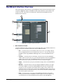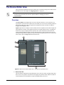
1
DashBoard Control and Monitoring
System
User Manual
DashBoard User Manual
•
Ross Part Number: 8351DR-004-5.0
•
Software version: 5.0
•
Release Date: May 2, 2012.
The information in this manual is subject to change without notice or obligation.
Copyright
© 2012 Ross Video Limited. All rights reserved.
Contents of this publication may not be reproduced in any form without the written permission of
Ross Video Limited. Reproduction or reverse engineering of copyrighted software is prohibited.
Patents
This product is protected by the following US Patents: 4,205,346; 5,115,314; 5,280,346;
5,561,404; 7,304,886; 7,508,455; 7,602,446; 7,834,886; 7,914,332. This product is protected by
the following Canadian Patents: 2039277; 1237518; 1127289. Other patents pending.
Notice
The material in this manual is furnished for informational use only. It is subject to change without
notice and should not be construed as commitment by Ross Video Limited. Ross Video Limited
assumes no responsibility or liability for errors or inaccuracies that may appear in this manual.
Trademarks
•
is a registered trademark of Ross Video Limited.
•
Ross, ROSS, ROSS®, and MLE are registered trademarks of Ross Video Limited.
•
openGear® is a regsitered trademark of Ross Video Limited.
•
DashBoard Control System™ is a trademark of Ross Video Limited.
•
Java and all Java-based marks are trademarks or registered trademarks of Sun
Microsystems, Inc. in the United States and other countries. Ross Video Limited is
independent of Sun Microsystems Inc.
•
Apple® Mac OS®, Leopard®, Snow Leopard™, and Lion™ are trademarks of Apple
Computer, Inc., registered in the U.S. and other countries.
•
Microsoft®, Internet Explorer®, and Windows® are either registered trademarks or
trademarks of Microsoft Corporation in the U.S.A. and/or other countries.
•
Linux®is the registered trademark of Linus Torvalds in the U.S. and other countries.
•
All other product names and any registered and unregistered trademarks mentioned in
this manual are used for indentification purposes only and remain the exclusive property
of their respective owners.
Environmental Information
The equipment that you purchased required the extraction and use of natural
resources for its production. It may contain hazardous substances that could
impact health and the environment.
To avoid the potential release of those substances into the environment and to diminsh the need
for the extraction of natural resources, Ross Video encourages you to use the appropriate
take-back systems. These systems will reuse or recycle most of the materials from your
end-of-life equipment in an environmentally friendly and health conscious manner.
The crossed out wheelie bin symbol invites you to use these systems.
If you need more information on the collection, resuse, and recycling systems, please contact
your local or regional waste administration.
You can also contact Ross Video for more information on the environmental performance of our
products.
Company Address
Ross Video Limited
Ross Video Incorporated
8 John Street
P.O. Box 880
Iroquois, Ontario, K0E 1K0
Ogdensburg, New York
Canada
USA 13669-0880
General Business Office: (+1) 613 • 652 • 4886
Fax: (+1) 613 • 652 • 4425
Technical Support: (+1) 613 • 652 • 4886
After Hours Emergency: (+1) 613 • 349 • 0006
E-mail (Technical Support): [email protected]
E-mail (General Information): [email protected]
Website: http://www.rossvideo.com
Contents
Introduction
1
Overview.............................................................................................................................. 1-2
Features.................................................................................................................. 1-2
Documentation Terms and Conventions.............................................................................. 1-4
Installing DashBoard
2
Before You Begin ................................................................................................................ 2-2
System Requirements ............................................................................................ 2-2
Installing the DashBoard Control System Client................................................................. 2-3
Creating a Backup of the Settings and Licensed Features .................................... 2-3
Installing on a Computer Running Microsoft® Windows® ................................. 2-3
Installing on a Computer Running Apple® Mac® OS® X .................................. 2-4
Installing on a Computer Running Linux® Fedora®............................................ 2-4
Removing DashBoard ........................................................................................... 2-4
Installing DashBoard Add-on Programs ............................................................... 2-5
Getting Started ..................................................................................................................... 2-6
Viewing Installation Details ................................................................................................ 2-7
DashBoard Installation Details Overview ............................................................. 2-7
Viewing Installation Details .................................................................................. 2-7
Viewing Error Logs............................................................................................... 2-8
Managing openGear Frames in DashBoard
3
Managing openGear Frames in DashBoard......................................................................... 3-2
Adding openGear Frames to DashBoard............................................................... 3-2
Re-naming an openGear Frame in the Tree View................................................. 3-3
Removing openGear Frames from a Tree View.................................................... 3-3
Using the DashBoard Interface
4
DashBoard Interface Overview ........................................................................................... 4-2
Status Indicators .................................................................................................... 4-3
DashBoard Basic Tree View................................................................................................ 4-5
Overview ............................................................................................................... 4-5
Using the Basic Tree View.................................................................................... 4-6
Using the Advanced Tree View........................................................................................... 4-8
Overview ............................................................................................................... 4-8
Using the Advanced Tree View .......................................................................... 4-10
The Device Editor Area ..................................................................................................... 4-12
Overview ............................................................................................................. 4-12
Using the Device Editor Feature ......................................................................... 4-13
Using Layouts .................................................................................................................... 4-15
Overview ............................................................................................................. 4-15
Managing Your Layouts...................................................................................... 4-16
Using DashBoard Help ...................................................................................................... 4-17
Configuring the DashBoard Help Display Options............................................. 4-17
DashBoard User Manual (Iss. 5.0)
Contents • i
Importing openGear Help .................................................................................... 4-18
Preferences ......................................................................................................................... 4-20
Secure Storage ..................................................................................................... 4-20
Web Browser ....................................................................................................... 4-20
DataSafe™
5
DataSafe Overview .............................................................................................................. 5-2
DataSafe Basics.................................................................................................................... 5-4
Saving a DataSafe File........................................................................................... 5-4
Restoring Configurations to Devices..................................................................... 5-4
Notes on Saving and Restoring Parameters........................................................... 5-6
Forcing DataSafe Updates ..................................................................................... 5-7
Configuring Devices
6
Configuring Online Devices in DashBoard ......................................................................... 6-2
Configuring Devices in DashBoard....................................................................... 6-2
Re-naming an openGear Slot in the Tree View..................................................... 6-2
Automatic Discovery ............................................................................................. 6-3
Troubleshooting ..................................................................................................... 6-4
Removing Devices from the Tree View ................................................................ 6-4
Using the File Navigator ...................................................................................................... 6-5
Upgrading Device Software ................................................................................................. 6-7
Upgrading Device Software .................................................................................. 6-7
Troubleshooting the Software Upload Process...................................................... 6-8
ii • Contents
DashBoard User Manual (Iss. 5.0)
Introduction
In This Chapter
This chapter contains the following sections:
•
A Word of Thanks
•
Overview
•
Documentation Terms and Conventions
A Word of Thanks
Congratulations on choosing the DashBoard Control System™. DashBoard is part of a full line of
Digital Products within the openGear Terminal Equipment family of products, backed by Ross
Video’s experience in engineering and design expertise since 1974.
You will be pleased at how DashBoard fits into your overall working environment. Equally
pleasing is the product quality, reliability and functionality. Thank you for joining the group of
worldwide satisfied Ross Video customers!
Should you have a question pertaining to the installation or operation of DashBoard, please
contact us at the numbers listed on the back cover of this manual. Our technical support staff is
always available for consultation, training, or service.
DashBoard User Manual (Iss. 5.0)
Introduction • 1–1
Overview
This manual provides an overview of installing, setting up, and using the DashBoard client. For
information on using the DashBoard Server and User Rights Management features, refer to the
DashBoard Server and User Rights Management User’s Guide.
The DashBoard Control System is built on Ethernet and TCP/IP technology, which allows remote
access across LAN architectures. DashBoard offers the ability to view multiple frames with full
control and alarming of all populated slots inside an openGear frame. This simplifies the setup of
numerous devices in a large installation and offers the ability to centralize monitoring. The
devices define their controllable parameters and layout to DashBoard, so the control interface is
always up-to-date.
Alarms raised by devices in the frame are reported at the upper most level, making it quick and
easy to identify potential failures or problems.
Monitoring
A network of openGear Connect compatible devices can be monitored, allowing users to quickly
isolate and correct potential problems from a central monitoring station.
Control
DashBoard offers real-time control of openGear Connect compatible devices. Parameter items
and menus vary depending on device functionality.
DataSafe™
DataSafe enables you to backup and restore device parameters to and from a single file, copy
parameters from one device to a another device or even a group of devices via DashBoard. This
feature allows you to hot-swap devices while retaining configurations, and DashBoard is not
required to have the parameters on the new device updated. You can update a subset of devices
instead of the entire connected view or to replace a device and have the previous device settings
automatically loaded onto the new device. When using openGear cards, this feature is available
for frames using the MFC-8310-N and MFC-8320-N Network Controller Cards series only.
Software Upgrades
You can upgrade the software and firmware on devices, such as openGear cards, in the field using
DashBoard. The upgrade utility verifies firmware and software upgrades against device hardware
and prevents accidental loading of incorrect files to the wrong hardware. DashBoard is designed
to allow for future feature plug-ins and upgrades to allow users the ability to customize control
and monitoring needs.
Features
The following features make DashBoard a unique system for your openGear requirements:
1–2 • Introduction
•
DashBoard software and manual are available for download from the Ross Video website
•
Store and upload configurations to multiple devices (using DataSafe)
•
Ability to perform batch software upgrades to allow multiple cards, of the same model, to
be upgraded at one time from any DashBoard terminal on the network
•
Customize views with the Advanced Tree View feature
•
Java™ based for installation in Microsoft® Windows®, Mac® OS, and Linux® Fedora®
•
Access multiple openGear frames on a single control network
DashBoard User Manual (Iss. 5.0)
•
Access multiple DashBoard applications on a single control network
•
Ability to have multiple control windows active and available on one screen
•
Automatic discovery of openGear Connect devices
•
Software and firmware upgrades via ethernet
•
Extensible plug-in architecture
DashBoard User Manual (Iss. 5.0)
Introduction • 1–3
Documentation Terms and Conventions
The following terms are used:
•
All references to the DFR-8300 series frame also includes all version of the 10-slot and
20-slot frames and any available options.
•
“Card” refers to openGear terminal devices within openGear frames, including all
components and switches.
•
“DashBoard window” refers to the main DashBoard client interface.
•
“Device” refers to an openGear Connect compatible product listed in DashBoard, such as
an openGear frame or card.
•
“Frame” refers to any openGear frame within your video system.
•
“Network Controller Card” refers to the MFC-8310-N series and MFC-8320-N series
cards unless otherwise noted.
•
“System” refers to the mix of interconnected production and terminal equipment in your
environment.
•
“Tree View” refers to the Basic Tree View and Advanced Tree View unless otherwise
noted.
•
“User” refers to the person who uses the DashBoard client.
The following conventions are used:
1–4 • Introduction
•
Navigation procedures assume that you are running Microsoft® Windows®. If you are
running Mac® OS or Linux® Fedora®, the menus names and options may differ.
•
Some navigation procedures state the menu items located on the main DashBoard toolbar
that you are to select followed by the “>” symbol. For example, File > New > Other.
•
Some navigation procedures state the button on your keyboard to press, followed by the
“+” symbol, followed by another button to press. For example, Shift + F4.
•
“Operating Tip” and “Note” boxes provide additional information.
DashBoard User Manual (Iss. 5.0)
Installing DashBoard
In This Chapter
This chapter provides instructions for installing the DashBoard Control System client software.
For information on installing the DashBoard URM and Server, refer to the DashBoard Server
and User Rights Management User Manual.
The following topics are discussed:
•
Before You Begin
•
Installing the DashBoard Control System Client
•
Getting Started
•
Viewing Installation Details
DashBoard User Manual (Iss. 5.0)
Installing DashBoard • 2–1
Before You Begin
Before installing any software for your DashBoard Control System client, ensure that you exit all
other programs currently running.
Note — Contact your I.T. Department if you experience communication issues with
DashBoard and are running anti-virus software. You may need to verify that there is
an exception in your firewall to allow DashBoard to receive TCP data via Port 5353.
System Requirements
Refer to the following sections for information on the system requirements for DashBoard.
Microsoft® Windows® XP/XP64/Vista/Vista64/7 Systems
The following are the minimum requirements when installing DashBoard on a Microsoft®
Windows® system:
•
Intel® Pentium 4, 1.6GHz (Intel® Core™ 2 Duo recommended)
•
1GB or more of RAM (2GB is recommended)
•
200MB available in HD space
•
Microsoft® Internet Explorer® version 5 (minimum)
Apple Mac® OS X 10.5 (Leopard®) / 10.6 (Snow Leopard™) / 10.7
(Lion™) Systems
The following are the minimum requirements when installing DashBoard on a Mac® OS system:
•
Intel® Core Duo processor
•
1GB or more of RAM (2GB is recommended)
•
200MB available HD space
•
Java® 6 installed
•
Mac® Safari®
Linux® Fedora® 9/10/11 Systems
The following are the minimum requirements when installing DashBoard on a Linux® system:
•
Intel® Pentium 4, 1.6GHz (Intel® Core™ 2 Duo recommended)
•
1GB or more of RAM (2GB is recommended)
•
200MB available in HD space
•
Version 2.2.1 GTK+ widget toolkit and associated libraries (GLib, Pango) are required
•
Mozilla® 1.4GTK2 or higher
2–2 • Installing DashBoard
DashBoard User Manual (Iss. 5.0)
Installing the DashBoard Control System Client
This section includes instructions on installing the DashBoard client to your computer. The
DashBoard software and user manual are available from the Ross Video website.
Creating a Backup of the Settings and Licensed Features
Regular backups of your DashBoard settings is recommended, or if you want to create a backup
of your DashBoard settings and license files, before installing a new version of DashBoard.
•
Microsoft® Windows® — DashBoard automatically uninstalls a previously installed
version, but not your settings.
›
To create a back up your settings Microsoft® XP® and earlier, navigate to the
metadata folder. Depending on your operating system version, this folder may be
located at c:\Program Files\DashBoard\ workspace. Copy the workspace folder
contents to a new location.
›
If you are running Microsoft® Vista® or higher, the metadata folder is at:
c:\DashBoard\workspace. Copy the folder to a new location.
•
Apple® Mac® OS® — DashBoard saves application information to the following
location on your computer: /Library/Application Support/openGear/DashBoard. To
create a backup of your settings, copy the workspace folder to a different location on
your system.
•
Linux® Fedora® — DashBoard creates a workspace directory inside of the current
DashBoard directory when the application is launched. To create a backup copy of your
settings, copy the workspace directory to a different location on your system.
Installing on a Computer Running Microsoft® Windows®
Note that if you are running Microsoft® Vista® or higher, the DashBoard main folder is at:
c:\DashBoard while previous Microsoft® operating systems will install DashBoard to
c:\Program Files\DashBoard.
Use the following procedure to install DashBoard on a computer running Microsoft®
Windows®:
Note — If you are upgrading your DashBoard Control System to software version
2.0, or higher, the Install Wizard automatically uninstalls any previous software
versions before proceeding.
1. Access the DashBoard software using one of the following methods:
•
Navigate to the Ross Video website and download the current software file.
•
Load the DashBoard software CD into the DVD/CD ROM tray of your computer.
2. If you are accessing the software from a CD, the Installation Wizard automatically
runs. If the Wizard does not automatically run, you can also install the DashBoard
software, navigate to your DVD/CD ROM drive in the Navigation Pane, so that the CD
contents are displayed in the Main Window of Windows Explorer.
3. Launch DBx.x.x-Win-setup.exe to begin installing the DashBoard program onto your
computer.
4. Follow the prompts to complete the installation of DashBoard onto your computer.
DashBoard User Manual (Iss. 5.0)
Installing DashBoard • 2–3
Installing on a Computer Running Apple® Mac® OS® X
Use the following procedure to install DashBoard on a computer running Apple® Mac® OS® X:
1. If you have a previous version of DashBoard installed, it is recommended that you
remove the DashBoard directory from the Applications folder before proceeding.
2. Access the DashBoard software using one of the following methods:
•
Navigate to the Ross Video website and click the link to the DashBoard installation
program for Apple OS X.
•
Load the DashBoard software CD into the DVD/CD ROM tray of your computer
and navigate to the DashBoard *.pkg file for Apple OS X.
3. Navigate to the *.pkg file you downloaded in step 2.
4. Double-click the *.pkg file to begin installing the DashBoard program onto your
computer.
5. Follow the prompts to complete the installation of DashBoard onto your computer.
Installing on a Computer Running Linux® Fedora®
Use the following procedure to install DashBoard on a computer running Linux® Fedora®:
1. If you have a previous version of DashBoard installed and want to keep your settings,
remove all folders, except the workspace directory, from the DashBoard directory. Note
that the uninstall function of DashBoard may delete the directory that also contains your
user data.
2. Access the DashBoard software using one of the following methods:
•
Navigate to the Ross Video website and click the link to the DashBoard.tar.gz file
for Linux.
•
Load the DashBoard software CD into the DVD/CD ROM tray of your computer.
3. Extract the new DashBoard.tar.gz file to your system. Note that this file contains a
top-level directory called DashBoard.
4. To run DashBoard, click the DashBoard icon in the top level of the DashBoard program
folder. Note that if you run DashBoard from the command line, ensure that you switch to
the main DashBoard directory before launching DashBoard.
Note — DashBoard creates a workspace directory where the application is
launched. This directory includes saved settings and licenses for optional features. To
provide consistent retrieval of saved settings and program features, Ross Video
recommends that you always launch Dashboard from within the same directory.
Removing DashBoard
Ensure to create a backup for your settings and licensed features as outlined the section
“Creating a Backup of the Settings and Licensed Features” on page 2-3 if you wish to retain
your user data before removing DashBoard from your computer.
To remove DashBoard from a computer running Microsoft® Windows®:
•
If you are using a computer running Microsoft® Windows®, use the Add/Remove
Software program located in the Windows® Control Panel.
•
Do not delete the DashBoard directory, instead run the Add/Remove Software program.
Deleting the directory without running the Add/Remove Software program results in a
2–4 • Installing DashBoard
DashBoard User Manual (Iss. 5.0)
number of dead registry and start menu items on your system. You can delete the
directory to remove your user data after you run the Add/Remove Software program.
To remove DashBoard from a computer running Apple® OS X®:
•
Remove your user data from the application support library directory.
•
Delete the Dashboard folder from your computer.
To remove DashBoard from a computer running Linux® Fedora®:
•
Ensure to create a backup for your settings and licensed features if you wish to retain
your user data.
•
Delete the Dashboard folder from your computer.
Installing DashBoard Add-on Programs
This section briefly outlines how to install Add-on programs for DashBoard such as:
•
openGear Extra Feature Pack — If you have an executable openGear Extra Feature
pack, and are running Microsoft® Windows®, use the following procedure to install your
feature pack. If you are not running Microsoft® Windows®, refer to the feature pack
documentation for installation details.
•
Unicode Font Support Pack — This program installs an international character set for
DashBoard and provides access to fonts capable of displaying all Unicode characters.
This program is not available for systems running Apple Mac® OS®. This option may be
required if you are using an openGear device designed with fonts not supported by the
base Java font system. Consult your device documentation for requirements and details.
Use the following procedure to install a DashBoard Add-on program:
1. Navigate to the openGear website (www.opengear.tv) and download the required add-on
program for your system.
2. If you are running Microsoft® Windows®:
•
Launch the Setup Wizard for your Add-on program by selecting the corresponding
*.exe file.
•
Follow the prompts to complete the installation of the Add-on program.
3. If you are running Linux® Fedora®:
•
Ensure you are in the main DashBoard directory before extracting the Add-on
program.
•
Copy the required *.zip to the main DashBoard directory.
•
Extract the *.zip file.
DashBoard User Manual (Iss. 5.0)
Installing DashBoard • 2–5
Getting Started
This section provides a brief introduction to launching the DashBoard client, and accessing some
of its features.
To launch DashBoard
1. Ensure that you have installed the DashBoard software as outlined in the section
“Installing the DashBoard Control System Client” on page 2-3.
2. Launch the DashBoard client by double-clicking its icon on your desktop.
3. If you are using DashBoard Server and URM, you will be prompted for a user name and
password.
Using the Full-screen mode
You can set the DashBoard interface to full-screen by performing one of the following:
•
Press Shift + F11.
•
Select Window > Full Screen from the main DashBoard toolbar.
To exit out of full-screen mode by performing one of the following:
•
Press Shift + F11.
•
Right-click the DashBoard icon in the system tray and unselect Full Screen.
Displaying multiple DashBoard windows
When operating in a multi-screen environment, you can open multiple DashBoard windows as
follows:
•
Select Window > New Window from the main DashBoard menu bar.
Locking the DashBoard window
You can lock the DashBoard window, preventing users from accessing the DashBoard client
running on your computer by performing one of the following:
•
Press Shift + F4.
•
Select Window > Lock Screen.
To unlock the interface:
•
2–6 • Installing DashBoard
Use the provided Unlock wheel.
DashBoard User Manual (Iss. 5.0)
Viewing Installation Details
You can view your installation history, activities in DashBoard, and error logs using the
DashBoard Installation Details dialog box available from the About DashBoard dialog box.
DashBoard Installation Details Overview
This section briefly explains the components of the DashBoard Installation Details dialog box
should you need to view it for troubleshooting purposes or as directed by Ross Video Technical
Support.
The DashBoard Installation Details dialog box includes the following tabs:
•
Installed Software tab — This tab displays the currently installed DashBoard
features, plug-ins, and application details. Details such as software version and ID
are also provided.
•
Installation History tab — This tab displays information on the current and any
previous configurations of DashBoard installed on your computer. Details such as
the date of installation and applications installed are also provided. From this
dialog, you can also Revert to any previously installed software using the Revert
button.
•
Plug-ins tab — This tab displays the ID, name, provider, and version of the
currently installed plug-ins, or add-on programs, for DashBoard.
•
Configuration tab — This tab displays information such as platform details,
system properties, and user preferences that can be used for troubleshooting.
Viewing Installation Details
Use the following procedure to view the installation details for your DashBoard client:
1. Launch DashBoard by double-clicking its icon on your desktop.
2. From the main DashBoard toolbar, select Help > About DashBoard > Installation
Details. The DashBoard Installation Details dialog box opens.
3. To view details on the currently installed software features and options for your
DashBoard application:
•
Select the Installed Software tab.
•
From the provided list, select the required software feature.
•
Click Properties.
4. To view details on your DashBoard installation history:
•
Select the Installation History tab.
•
Select the required configuration from the Previous configurations: list.
•
The Configuration contents pane updates to include a list of the features and
options.
5. To view details on the installed plug-ins for your DashBoard application:
•
Select the Plug-ins tab.
•
Select the required plug-in from the provided list.
•
Click Legal Info to display the plug-in licensing agreement.
DashBoard User Manual (Iss. 5.0)
Installing DashBoard • 2–7
•
Click Show Signing Info to display a new pane that includes the signing date and
the signing certificate for the selected plug-in. Click Hide Signing Info to close
the pane.
•
Click Columns to configure how information is displayed in the Plug-ins tab.
Viewing Error Logs
If you are troubleshooting problems in DashBoard, Ross Technical Support may request that you
view the error logs for your local DashBoard application.
To view the error log for your DashBoard application
1. From the main DashBoard toolbar, select Help > About DashBoard > Installation
Details. The DashBoard Installation Details dialog box opens.
2. Select the Configuration tab.
3. Click View Error Log to display the Open With dialog box.
4. Select an application to view the error log information in.
5. Click OK. The error log displays in the selected application.
2–8 • Installing DashBoard
DashBoard User Manual (Iss. 5.0)
Managing openGear Frames in
DashBoard
In This Chapter
The DFR-8300 series frames offers remote control and monitoring with the combination of the
openGear Network Interface card and the DashBoard Control System™. This allows users to
remotely monitor and control parameters on openGear Connect compatible devices, such as
openGear frames and cards. DashBoard connects to an openGear frame using a TCP/IP LAN
connection.
This chapter provides instructions for managing openGear frames in the DashBoard Control
System.
Note — For details on configuring your openGear frame and Network Controller
Card, refer to the DFR-8300 Series User Manual and the MFC-8300 Series User
Manual.
The following topic is discussed:
•
Managing openGear Frames in DashBoard
DashBoard User Manual (Iss. 5.0)
Managing openGear Frames in DashBoard • 3–1
Managing openGear Frames in DashBoard
When DashBoard is launched, openGear frames are automatically discovered and are available in
the Tree View where they can be custom identified, collapsed to view just the frame or opened to
view available devices in the frame.
This section includes information for enabling DashBoard to auto-connect to openGear frames,
manually adding and re-naming frames to the Tree View, and removing frames from the Tree
View.
Refer to the section “DashBoard Basic Tree View” on page 4-5 for information on using the
Basic Tree View. For information on using the Advanced Tree View, refer to the section “Using
the Advanced Tree View” on page 4-8. It is assumed that if you have the DashBoard Server and
URM feature installed, that your user account is configured for write access to the frames
communicating with your DashBoard client.
Adding openGear Frames to DashBoard
Each openGear frame lists all devices within the frame, and provides status information in the
Tree View. You can also remove and disconnect an openGear frame from DashBoard. There are
two methods for adding an openGear frame to the tree view: using the auto-connect feature or
manually adding a frame by specifying the IP address of the frame. Both methods are described in
this section.
Using the Automatic Detection Feature
By default, the DashBoard Control System auto-detects any openGear frame on the same IP
subnet. How often DashBoard queries the network for new frames (the default is every 10
seconds) depends on how the Automatic Detection feature is configured in the Preferences
menu. Refer to the section “Automatic Discovery” on page 6-3 for setup details. Refer to the
section “DashBoard Basic Tree View” on page 4-5 for information on the toggling the
Auto-Connect Devices button.
Manually adding openGear Frames to DashBoard
You will need to manually add openGear frames to the Tree View when the frame is on a different
subnet from your computer running the DashBoard client.
Use the following procedure to manually add an openGear frame to a DashBoard Tree View:
1. Click
on the Tree View toolbar to open the Select Equipment or Service Type to
Add dialog box.
2. Expand the openGear node.
3. Select TCP/IP openGear Frame.
Operating Tip — You can also select File > New > TCP/IP openGear Frame
from the main DashBoard toolbar.
4. Click Next > to open the New TCP openGear Frame Connection dialog box. The
Invalid host name or IP address message remains until you enter text in the IP
Address field.
3–2 • Managing openGear Frames in DashBoard
DashBoard User Manual (Iss. 5.0)
5. In the text fields provided, enter the IP Address, display name for the frame, and port of
the openGear frame you wish to add.
Operating Tip — You can also click Detect Frame Information to enable
DashBoard to detect the port, name, unique identifier and other connection
information from the specified IP Address. Once DashBoard detects the information,
the Automatically Track Updates to Frame Information check box is selected so
that any changes are automatically updated in DashBoard.
6. Click Finish to display the openGear frame in the Tree View. Frames added to the Tree
View are also displayed in the Advanced Tree View.
7. Repeat the procedure for each openGear frame that you wish to add to the Tree View.
Re-naming an openGear Frame in the Tree View
There are two methods for re-naming an openGear Frame in DashBoard. The first method is for
frames manually added to the Tree View as described in the section “Adding openGear Frames
to DashBoard” on page 3-2. The second method describes how to re-name an auto-detected
frame using the DashBoard menu options available on the MFC-8300 series cards. Both methods
are described below.
To re-name a manually added openGear frame
1. Right-click the frame you wish to rename.
2. Select Rename Frame.
3. Enter the new name for the frame in the text field provided.
Note — This option is not available if you enabled the Automatically Track
Updates to Frame Information option. When this option is enabled, follow the steps
outlined in the section “To re-name an Auto-Detected openGear frame”.
4. Click OK.
To re-name an Auto-Detected openGear frame
1. Right-click the frame you wish to rename.
2. Select Open to display a Device Editor tab. Note that the tab title displays the name of
the frame, and information about the MFC-8300 series Network Controller Card
currently installed in the frame.
3. Select the Network tab.
4. Enter a new name for the frame in the Frame Name field.
5. Press Enter.
6. Click Apply.
Removing openGear Frames from a Tree View
This section outlines how to remove an openGear frame from a Tree View in DashBoard. Once a
frame is removed, DashBoard no longer reports the status in the Tree View and you are no longer
able to monitor or control the affected devices. If communication with a frame is disconnected via
the Disconnect option, the status indicator is light gray until the frame is re-connected. If the
status indicator is dark gray, with the rest of the node displaying as normal, a connection cannot
currently be established to the device.
DashBoard User Manual (Iss. 5.0)
Managing openGear Frames in DashBoard • 3–3
To remove or disconnect an openGear frame from the Tree View
1. If the frame you are removing is in a Custom Folder, you must first delete the frame
from the Custom Folder before it can be removed from the Tree View.
2. To remove a manually added openGear frame from the Tree View:
•
Right-click the openGear frame you wish to remove.
•
Select
to remove the openGear frame from the Tree View.
3. To disconnect communications to an openGear frame from DashBoard:
•
Toggle
to off.
•
Right-click the openGear frame you wish to disconnect.
•
Select
•
The frame status indicator is grayed out in the Tree View.
.
4. To re-connect to an openGear frame:
•
Right-click the frame status indicator.
•
Select
or toggle
to on.
Auto-Discovery
Selecting
for an auto-detected frame will temporarily remove the frame but the frame will
re-appear in the Tree View again due to the auto-discovery feature of DashBoard. You must first
disable the auto-discovery feature before you can remove a frame in this instance. Refer to the
section “Automatic Discovery” on page 6-3 for details on configuring the auto-discovery
feature.
However, you can still disconnect from an auto-discovered frame by toggling the Automatic
Discovery option off.
3–4 • Managing openGear Frames in DashBoard
DashBoard User Manual (Iss. 5.0)
Using the DashBoard Interface
In This Chapter
DashBoard allows for multiple Device Editor tabs to be active and available on one screen which
is useful when a functional path involves more than a single device. These tabs can be saved and
recalled as a layout, allowing for quick access to frequently used devices. Layouts can consist of
a single device window, multiple device windows displayed full screen in tabs, or multiple
devices on a shared screen.
This chapter introduces you to the DashBoard client interface, how to access menus and tabs, and
how to manage your layouts.
Note — Contact your I.T. Department if you experience communication issues with
DashBoard and are running anti-virus software. You may need to verify that there is
an exception in your firewall to allow DashBoard to receive TCP data via Port 5353.
The following topics are discussed:
•
DashBoard Interface Overview
•
DashBoard Basic Tree View
•
Using the Advanced Tree View
•
The Device Editor Area
•
Using Layouts
•
Using DashBoard Help
•
Preferences
DashBoard User Manual (Iss. 5.0)
Using the DashBoard Interface • 4–1
DashBoard Interface Overview
This section includes a brief summary of the DashBoard Control System client interface and its
components. Figure 4.1 displays a DashBoard window that includes the Custom Folders and
Layouts View tabs. These tabs are not displayed by default when the DashBoard client is
launched for the first time.
1
3
2
4
5
Figure 4.1 DashBoard Interface Overview
1. Main DashBoard Toolbar
The Main DashBoard toolbar provides access to menus that enable you to manually add devices,
manage your layouts, and enable different tabs in the DashBoard window.
•
File — From this menu you can manually add a device (New), save changes made to
device configuration files on your computer (Save, Save As..., Save All), log-off from
DashBoard when using DashBoard URM (Sign Out), or close the DashBoard client
(Exit).
•
Layouts — From this menu you can display a Layouts View tab in the DashBoard
window (Show Layouts View), save your current arrangement of tabs in the DashBoard
window (Save Layout), lock the DashBoard window to its current state (Maintain
Window State/Size/Location), or select from a list of saved layouts to apply.
•
Views — From this menu you specify which tabs to display in the current DashBoard
window.
•
Window — From this menu you can open multiple DashBoard windows on a single
screen (New Window), restore the default DashBoard client layout of tabs (Refresh
Perspectives), show or hide the main toolbar (Show Toolbar), set the window to the
maximum screen size (Full-screen), lock the current DashBoard window (Lock Screen),
and set preferences for Automatic discovery of devices on your subnet, automatic login,
and software updates (Preferences).
•
Help — From this menu you can access the DashBoard online help system (Help
Contents), perform checks for DashBoard software updates (Check for Updates), and
view details about your current DashBoard client software (About DashBoard).
4–2 • Using the DashBoard Interface
DashBoard User Manual (Iss. 5.0)
2. Device Editor
This area displays tabs for each device that you double-click from the Tree View. From this view
you can verify the device and connection status, update device parameters, and view read-only
device information.When shutting down and then re-starting the DashBoard client, the Device
Editor tab state is also saved/restored. Refer to the section “The Device Editor Area” on
page 4-12 and your device manual for more information.
3. Basic Tree View Tab
This area lists the devices, such as openGear frames and the cards installed in each frame, that can
communicate with DashBoard. From this tab you can open Device Editors, enable or disable auto
connections to devices, re-query the network for new devices, manually add new connections,
and delete devices from the Tree View. Refer to the section “DashBoard Basic Tree View” on
page 4-5 for more information.
4. Advanced Tree View Tabs
The Advanced Tree View feature enables you to create a customized hierarchy of folders and
subfolders in a single tab, where each folder can be expanded to display a list of devices and/or
subfolders. You can re-organize your devices in a Custom Folder tab to suit your workflow by
dragging and dropping devices from the Basic Tree View to any open Custom Folder tab. Note
that this tab is not displayed by default. For more information on using Custom Folders, refer to
the section “Using the Advanced Tree View” on page 4-8.
5. Layouts View Tab
This feature enables you to save and restore a series of Device Editor tabs and the DashBoard
window size and position as a layout. Layouts can be recalled using the options in the Main
DashBoard toolbar or from a Layouts View tab. Note that saving/restoring a layout restores the
current Device Editor tab selection, the divider position and scroll position in opened Device
Editor tabs. Note that this tab is not displayed by default. For more information on layouts, refer
to the section “Using Layouts” on page 4-15.
Status Indicators
Some device include a status indicator beside its node in the Tree Views, custom folders and
subfolders. These indicators may change color to indicate the status of devices as follows:
•
Green — This color indicates that the device is running correctly and communicating
with the frame.
•
Orange — This color indicates that the MFC-8300 Network Controller Card for that
frame can only support a limited number of connections and that maximum has been
reached. You can select the Force Connect option, after right-clicking on the frame
status indicator, to establish a connection between the frame and your DashBoard
workstation. However, doing so will disconnect another connection to the same
MFC-8300 Network Controller card.
•
Yellow — This color indicates a minor problem with the device.
•
Red — This color indicates that the device has a significant error condition. For
example, there is no input or reference signal from the card.
•
Gray — This color indicates the device is currently offline and cannot communicate with
DashBoard. The offline status is also reflected in its Device Editor tab.
•
icon — If the status indicator is replaced by this symbol, the user does not have
permission to view/modify the device. In the case of an openGear frame, this icon means
the frame parameters are locked and the Master Password is required to use it. Refer to
DashBoard User Manual (Iss. 5.0)
Using the DashBoard Interface • 4–3
the DashBoard Server and URM User Manual and the MFC-8300 Series User Manual
for details. When a device has this icon, there are no editable parameters underneath it.
Note — The Frame Status Indicator, the Custom Folders, and the subfolders
reflect the most severe status of any detected devices.
4–4 • Using the DashBoard Interface
DashBoard User Manual (Iss. 5.0)
DashBoard Basic Tree View
This section outlines the Basic Tree View of the DashBoard client. For details on using the
Advanced Tree View feature, refer to the section “Using the Advanced Tree View” on page 4-8.
Overview
The Basic Tree View displays devices, such as openGear frames and cards, in a tree structure.
When you launch DashBoard, all devices within the same subnet are auto-detected unless this
feature is disabled in the tab toolbar. Refer to the section “Managing openGear Frames in
DashBoard” on page 3-2 for information on adding openGear frames to the Basic Tree View. For
information on connecting your openGear frame using a TCP/IP connection, refer to your frame
user manual or your facility IT personnel.
The Basic Tree View also displays the devices and status information of each device, allowing
you to monitor and control devices from a single computer. The Basic Tree View includes a Filter
feature that enables you to search this hierarchy by entering text into the field. Figure 4.2
provides an example of a Basic Tree View.
1
2
3
4
Figure 4.2 Example of a Basic Tree View
1. Basic Tree View Toolbar
This area provides access to the following basic tasks:
•
Device Editor Button — Selecting this button enables you to view a Device
Editor tab of a selected device. To view a Device Editor tab, click the device you wish to
edit from the tree view, and select this button. You can also double-click the device from
the Basic Tree View list. You can also open additional copies of a Device Editor tab by
right-clicking the node and select Open; the active tab is the one displayed in the
foreground.
•
Auto-Connect Devices Button — Toggling this button enables DashBoard to
automatically connect to devices and display information in the Basic Tree View. The
default setting is enabled (auto-connect).
•
Re-query the Network Button — Selecting this button enables DashBoard to
query the network and automatically add any new devices to the Basic Tree View. Note
that DashBoard automatically queries the network approximately every 10 seconds. If
Automatic Discovery is disabled, you can force a network query by selecting this button.
DashBoard User Manual (Iss. 5.0)
Using the DashBoard Interface • 4–5
•
Add New Connection Button — Selecting this button opens the New dialog box
and enables you to manually add a device, such as an openGear frame, to the Basic Tree
View. Use this button to add a device that cannot auto-connect but can be found via the
network.
•
Delete Button — Selecting this button enables you to delete a selected offline or
manually added device from the Basic Tree View.
•
Group Similar Devices Button — This button determines how devices are
displayed in the Tree View. When toggled on, devices are grouped by class. When
toggled off, the Tree View is sorted alphabetically.
2. Filter Search Field
Each Custom Folder includes a Filter feature that enables you to search the Tree View by entering
text into the field. DashBoard automatically displays the search results in the selected tab under
the All Connections node. For example, to search for a UDC-8225, enter 8225 in the Filter field
and the tab only lists the frames that have a UDC-8225 installed. Expand the frame nodes inside
the All Connections node to display the specific slots with UDC-8225 cards. To clear the Filter
field, delete the text.
3. openGear Frame Status Indicator
A status indicator is displayed for each openGear frame detected by DashBoard and is located to
the left of the frame name. This status indicator summarizes the current status of the detected
devices in that specific openGear frame. For example, FRAME 2 in Figure 4.2 indicates a red
status because at least one card is reporting a red status (in this case there are three). A , or an
arrowhead, next to a status indicator signifies that the list can be expanded to display a list of
devices installed in that frame.
4. Device Status Indicator
A status indicator is listed for each openGear Connect compatible device. This icon includes the
card status, the slot in which it is installed in that frame, and the device product name. This
information is detected automatically. To view a device in the Device Editor, double-click its
status indicator. Note that if the device is offline, you cannot open a tab for it in the Device Editor
area.
Using the Basic Tree View
This section briefly summarizes how to use the Basic Tree View features.
To open or close the Basic Tree View tab
•
To open a tab, select Views > Basic Tree View.
•
To close a tab, right-click the Basic Tree View tab, then select Close.
To enable automatic discovery
Note that this method is applicable to all tree views.
1. Confirm the Automatic Discovery feature settings by selecting Window > Preferences.
Note that by default, this feature is enabled and DashBoard polls for devices every 10
seconds.
2. Toggle
on the Basic Tree View toolbar to enable DashBoard to automatically
connect to the listed devices in the Basic Tree View.
4–6 • Using the DashBoard Interface
DashBoard User Manual (Iss. 5.0)
To manually add a device to the Basic Tree View
1. Click
on the Basic Tree View toolbar to display the Select Equipment or Service
Type to Add dialog box.
2. Add a connection by following the on-screen instructions.
To display a Device Editor tab
Display a Device Editor tab using one of the following methods:
•
From the Basic Tree View, double-click the device node.
•
From the Basic Tree View, select the device to edit. Click
toolbar.
on the Basic Tree View
To remove a device from the Basic Tree View
1. Select the device to remove from the Basic Tree View.
2. Click
on the Basic Tree View toolbar to display the Confirm tree item removal
dialog box displays.
3. Click OK.
DashBoard User Manual (Iss. 5.0)
Using the DashBoard Interface • 4–7
Using the Advanced Tree View
The Advanced Tree View feature enables you to display a tab that you can customize with a
layout of folders. A folder can display any number of devices or subfolders of devices in a single
tab. This feature allows you to drag and drop devices into subfolders, enabling you to quickly
customize folders as required. For example, you may wish to create a folder that lists only the
UDC-8625 cards installed in your facility.
All device information is automatically updated whenever parameters or status changes occur.
You can have multiple custom folder tabs open or have multiple Advanced Tree View tabs open
in a single DashBoard window.
Overview
This section summarizes the Advanced Tree View tabs, Custom Folders and subfolders, and the
available menu options.
1
2
3
6
4
5
Figure 4.3 Advanced Tree View
1. Custom Folder Toolbar
Like the Basic Tree View, the Custom Folder toolbar includes the Device Editor, Delete and Add
New Connection buttons, saving the current tree view, saving and restoring device configuration,
and accessing the extra menu options of the Custom Folders tab. In addition, there is a button for
creating new subfolders. You can save the current tree view using the
button in the main
DashBoard toolbar.
2. Filter Search Field
Each Custom Folder includes a Filter feature that enables you to search the Tree Views by
entering text into the field. DashBoard automatically displays the search results in the selected tab
under the All Connections node. For example, to search for a UDC-8625, enter 8625 in the Filter
field and the tab only lists the frames that have a UDC-8625 installed. Expand the frame nodes
inside the All Connections node to display the specific slots with UDC-8625 cards. To clear the
Filter field, delete the text.
4–8 • Using the DashBoard Interface
DashBoard User Manual (Iss. 5.0)
3. Custom Folders
Each Advanced Tree View tab includes a main Custom Folder. In this folder, you can create and
re-name subfolders to organize devices for customized views. The status indicator represents the
current status of the devices in the custom subfolder. If a device in the subfolder needs attention,
the status indicator shows the most critical warning level. For example, the Custom Folders icon
in Figure 4.3 indicates a red status because the UDC-8225 in FRAME 1 and the DRA-8204 in
FRAME 6 are reporting an error conditions.
Right-clicking a custom folder displays a dialog that includes options for creating a new
subfolder, connecting or disconnecting devices, and re-naming the folder. To add devices to a
Custom Folder, simply drag a device or frame from the All Connections directory to the desired
Custom Folder.
4. Custom Subfolders
A Custom Subfolder displays the devices connected to DashBoard that you have specified.
Creating Custom Subfolders allows you to group similar devices together that may be installed in
different frames, such as the folders in Figure 4.3. If a device in the subfolder needs attention, the
status indicator shows the most critical warning level. For example, the Reclockers subfolder in
Figure 4.3 indicates a red status because the DRA-8204 in FRAME 6 is reporting an error
condition (a red status).
Right-clicking a subfolder displays a dialog that includes options for creating a new
sub-subfolder, connecting or disconnecting devices, re-naming the folder, removing the selected
subfolder, saving and recalling configuration folders.
5. Device Status Indicator
A status indicator is listed for each device in a subfolder. This icon includes the device status, the
slot and frame in which it is installed (if it is an openGear card), and the device product name.
This information is detected automatically, but you can also re-name an openGear frame or card
as required. To view a Device Editor tab, double-click the device node. Right-clicking a device
displays a menu that includes options for opening the device, restoring or saving the
configuration, re-naming the device or removing the device.
6. Custom Folders Extra Options
You may need to select the
Options.
button on the Custom Folder toolbar to display the available Extra
•
New Advanced Tree View tab — This option opens a new Advanced Tree View
tab in DashBoard.
•
Clear This Advanced Tree View tab — This option closes the current Advanced
Tree View and opens a new Advanced Tree View in its place. If you have made any
changes to the current Advanced Tree View, you will be prompted to save your work.
•
Open Advanced Tree View — This option enables you to select a previously saved
Advanced Tree View to open in the current session of DashBoard.
•
Save Advanced Tree View — This option saves the selected Advanced Tree
View. If you have re-named the main Custom Folder, the new name is now displayed. An
asterisk displays next to the Custom Folder tab name when there are unsaved changes for
that tab.
•
Save Advanced Tree View As… — This option saves the selected Advanced
Tree View under a new filename.
•
Import Advanced Tree View — This option enables you to import an Advanced
Tree View from another location or DashBoard computer.
•
Export Advanced Tree View — This option enables you to export an Advanced
Tree View to another location or DashBoard computer.
DashBoard User Manual (Iss. 5.0)
Using the DashBoard Interface • 4–9
•
New Folder — This option enables you to create a new subfolder in the Advanced
Tree View.
•
Save Configuration to File — This option is only available when using the
MFC-8310-N and MFC-8320-N Network Controller Cards. For more information on this
feature, refer to the section “DataSafe Overview” on page 5-2.
•
Restore Configuration — This option is only available when using the
MFC-8310-N and MFC-8320-N Network Controller Cards. For more information on this
feature, refer to the section “DataSafe Overview” on page 5-2.
•
Show Device List — Selecting this option displays or hides the list of connected
frames and devices in the Advanced Tree View tab.
•
Delete Advanced Tree View — This option deletes the current Custom Folder
from DashBoard.
Using the Advanced Tree View
This section briefly summarizes how to use the Advanced Tree View features.
To open a new Advanced Tree View tab in DashBoard
1. From the DashBoard main toolbar, select Views > Advanced Tree View > New
Advanced Tree View Tab.
To add a new subfolder to the Custom Folders
1. On the Custom Folders toolbar, select
display a list of available functions.
. If you do not see this button, click
first to
2. You are prompted to enter a name for the new subfolder. An asterisk (*) displays at the
top of the Custom Folders tab to remind you to save the this tab.
To add devices to a subfolder
1. Select the device from the All Connections or any available Tree View.
2. Drag and drop the device status indicator to the desired subfolder. The Add to Custom
Folder? dialog box displays.
Operating Tip — You can re-organize devices in a subfolder using the drag and
drop method.
3. Re-name the device, if desired, by entering a new name in the Name Prefix field. Note
that the new name only applies to the device in the Custom Folder view.
4. Click OK.
To re-name a subfolder
1. Right-click the subfolder icon.
2. Select Rename to display the Rename dialog box.
3. Enter the new name in the Name: field.
4. Click OK.
4–10 • Using the DashBoard Interface
DashBoard User Manual (Iss. 5.0)
To save an Advanced Tree View tab
•
On the Custom Folders toolbar, select
display a list of available functions.
. If you do not see this button, click
first to
To clear an Advanced Tree View tab
•
On the Custom Folder toolbar, select
display a list of available functions.
. If you do not see this button, click
first to
To open or close an Advanced Tree View tab
•
To open a tab, select Views > Advanced Tree View.
•
To close a tab, right-click the Custom Folders tab, then select Close.
DashBoard User Manual (Iss. 5.0)
Using the DashBoard Interface • 4–11
The Device Editor Area
This section briefly summarizes the Device Editor area. For details on using Device Editor tabs in
DashBoard, refer to the chapter “Configuring Devices” on page 6-1.
Note — Some devices may not have Device Editors as presented here. Refer to
the manual that came with your device for specific details on managing your device
using DashBoard.
Overview
The Device Editor area displays tabs for devices selected from the tree views. Each device is
represented as a tab in the Device Editor area from which you can access the available parameters
and menus for that device.You can organize the arrangement of tabs in the Device Editor by
dragging and dropping the tabs.
Figure 4.4 provides an example of a Device Editor tab for an openGear card. In this example, the
status indicator, the name of the openGear frame, the slot number that the device is installed in,
and the device type are displayed on the top left corner, status information in the bottom left
corner, and the available parameters used to control the device in the right-side of the tab. The
information and parameters displayed in a Device Editor tab depends on your device and may not
reflect what is shown in Figure 4.4 and described below.
1
2
3
4
5
Figure 4.4 Device Tab in Device Editor Area — Example of an openGear Card
1. Device Tab Title
This area displays information to help identify the device such as its status, and the product name.
If the device is an openGear card, this tab also displays the openGear frame and the slot that the
card is installed in. This information is reported automatically by the device.
4–12 • Using the DashBoard Interface
DashBoard User Manual (Iss. 5.0)
2. Status Overview
Your device may include an area that reports the operating status and communication activity.
3. Read-Only Information
Your device may include an area that displays read-only information such as the status parameters
as reported by the device. The parameters and options in this area are dependant on the device
selected, but can include the product details such as software versions, hardware information, and
signal status. In Figure 4.4, the tabs are named Product, Hardware, and Signal, and display as
read-only fields.
4. Settings and Parameters Area
The contents of this area are dependant on the device selected but can include source selection,
video format and timing settings, alarm reporting options, and audio parameters. All changes to
openGear card parameters are immediate. Refer to your device manual for details.
5. Button Area
The following buttons may be available:
•
Refresh — Use this button to request the latest information from the device.
•
Upload — Use this button to upload new software to the device.
•
Reboot — Use this button to instruct the device to reboot.
•
Close — Use this button to close the current Device Editor tab.
Using the Device Editor Feature
This section briefly summaries how to use some of the Device Editor features.
To display a Device Editor tab
Display a Device Editor tab using one of the following methods:
•
Double-click a device in a Tree View.
•
Right-click the device in a Tree View and select Open.
•
Drag and drop the device from the Tree View to the Device Editor area.
To refresh the parameters of a device
•
Click Refresh on the Device Editor tab.
To maximize or minimize a Device Editor tab
1. Right-click the applicable Device Editor tab.
2. Select Maximize or Minimize from the menu.
To organize the Device Editor tabs
Organize tabs using one of the following methods:
•
Dock or undock the Advanced Tree View and Layout List from the DashBoard window
by dragging it outside the DashBoard window.
•
Drag and drop the Device Editor tabs to organize a layout as required. For information on
saving and recalling layouts, refer to the section “Using Layouts” on page 4-15.
DashBoard User Manual (Iss. 5.0)
Using the DashBoard Interface • 4–13
To close a Device Editor tab
1. Right-click the Device tab you wish to close.
2. Select one of the following options:
•
Close — Closes the selected Device Editor tab.
•
Close Others — Closes all other Device Editor tabs in the group but the
highlighted tab.
•
Close All — Closes all Device Editor tabs in that Tab Group.
4–14 • Using the DashBoard Interface
DashBoard User Manual (Iss. 5.0)
Using Layouts
This section summarizes the Layout feature of the DashBoard client interface. Information on
creating, saving, and managing layouts in the Device Editor is also included.
Overview
Layouts are used to save window configurations in your DashBoard interface. For example, you
can save a layout which shows a certain set of devices open in the Device Editor area, two
Custom Folder tabs, each with a specific size and location on the screen. You can also determine
how these Device tabs are displayed (tabbed, tiled, or in groups), and whether any Custom Folder
tabs are included.
When a layout is saved, it captures details such as how each component of DashBoard is
displayed, including the state of any Device Editor tabs, the current tab selection, divider
positions between tabs, and scroll position in Device Editor tabs.
Each layout also saves the DashBoard window state, size, and position. Note that the size and
position of any undocked tabs are also saved. When restoring layouts from the Layout List, you
can toggle whether to use the stored layout, or the current layout, of the open window with the
three right-hand buttons on the toolbar.
Layouts View Tab
The following buttons are available in the toolbar of the Layout List, from left to right:
•
Save Layout — Use this button to open the Save Current Layout dialog box.
•
Delete the Selected Layout — Use this button to delete the currently selected
layout in the Layout List.
•
Maintain Window State — Click this button to keep the DashBoard window at its
current state when restoring a layout (maximized or sized). Click the button again to turn
off this feature.
•
Maintain Window Size — Click this button to keep the DashBoard window at its
current size when restoring a layout (if not maximized). Click the button again to turn off
this feature.
•
Maintain Window Position — Click this button to keep the DashBoard window
at its position on the desktop when restoring a layout. Click the button again to turn off
this feature.
DashBoard User Manual (Iss. 5.0)
Using the DashBoard Interface • 4–15
Managing Your Layouts
Once your DashBoard window and Device tabs are organized the way you wish, you can save
this configuration as a new Layout.
To display a Layouts View tab
Display a Layouts View tab using one of the following methods:
•
Select Layouts > Show Layouts View.
•
Select Views > Show Layouts.
To organize the tabs
1. Click the tab you wish to move.
2. Drag and drop the tab to the new location within the DashBoard window.
To re-position a tab in DashBoard
1. Click the tab you wish to move.
2. Position a tab using one of the following methods:
•
Drag and drop the tab to the new location within the DashBoard window.
•
Undock the tab from the DashBoard window by dragging it outside the DashBoard
window.
To save the current layout
1. Click
in Layouts View tab to display the Save Current Layout dialog box.
2. Enter a name for the new layout in the provided text field.
3. Click OK.
To recall a layout
Recall a layout using one of the following methods:
•
Select Layouts from the main DashBoard toolbar. Select a layout from the provided list.
•
From the Layouts View tab, double-click the name of the layout. DashBoard restores the
tab selection, divider position, and scroll position of any Device Editor tabs that were
opened when the layout was last saved.
To rename a layout
1. Right-click the layout in the Layouts View tab.
2. Select Rename to open the Rename Layout dialog box.
3. Enter a new name for the layout in the provided text field.
4. Click OK. The new name for the layout displays in the Layouts View tab.
To delete a layout
1. From the Layouts View tab, select the layout you wish to delete.
2. Click
to display the Confirm Layout Delete dialog box.
3. Click OK. The layout is deleted from the Layout List.
4–16 • Using the DashBoard Interface
DashBoard User Manual (Iss. 5.0)
Using DashBoard Help
The DashBoard Help system is accessed by selecting Help > Help Contents from the main
toolbar of DashBoard. The DashBoard Help displays, by default, the Contents pane and Search
box in the toolbar.
The following Help Systems are currently available in DashBoard:
•
DashBoard Help — This is the main Help system for the DashBoard Control System
that is available by choosing Help > Help Contents from the main toolbar. DashBoard
Help provides information on the various features and options available in DashBoard.
Context-sensitive Help is also available by selecting an interface item, such as the Basic
Tree View tab, and clicking F1 (when running Microsoft® Windows®).
•
openGear Help — This feature provides information on individual openGear devices,
such as frames and cards. You can access the openGear Help for your device by selecting
the device in the Tree Views and clicking F1 (when running Microsoft® Windows®) or
by choosing openGear from the Help dialog box. An option is provided for importing
new help files for openGear devices.
•
URM Help — This feature provides information on the DashBoard User Rights and
Management option.
This section briefly summarizes how to configure the DashBoard Help display options and
import new help files.
Configuring the DashBoard Help Display Options
This section summarizes how to configure the DashBoard Help display features:
•
Open Window Context Help — This is the context-sensitive help that is displayed when
you click F1 (when using Microsoft® Windows®) in the main DashBoard window.
•
Dialog Context Help — This is the context-sensitive help in a dialog box.
Use the following procedure to configure the Help display options for DashBoard:
1. Select Window > Preferences to display the Preferences dialog box.
2. Select Help to display the Help dialog box.
3. Specify the browser used to display the DashBoard Help search results by selecting one
of the following options from the Open help search menu.
•
In the dynamic help view — Select this option to display the DashBoard Help
search results in a new pane of the DashBoard interface. This is the default setting.
•
In a browser — Select this option to display the DashBoard Help search results in
your default web browser.
4. Specify how to display help documents, such as user manuals in *.pdf format, by
selecting one of the following options from the Open help view documents menu.
•
In place — The help document is displayed in the same tab as the link to the
document. This is the default setting.
•
In the editor area — The help document is displayed in a new tab in DashBoard.
•
In a browser — The help document is displayed in your default web browser.
5. Specify how to display the DashBoard Help contents by selecting one of the following
options from the Open help contents menu.
•
DashBoard User Manual (Iss. 5.0)
In the help browser — The DashBoard Help content is displayed in a new pane of
the DashBoard interface. This is the default setting.
Using the DashBoard Interface • 4–17
•
In an external browser — The DashBoard Help content is displayed in your
default web browser.
6. Specify how the openGear Help is displayed by selecting one of the following options
from the Open window context help menu:
•
In the dynamic help view — The selected Dialog Context Help is displayed in a
new pane of the DashBoard interface. This is the default setting.
•
In an infopop — The Help content is displayed as a persistent popup message.
7. Specify how to display the openGear Help by selecting one of the following options
from the Open dialog context help menu.
•
In a dialog tray — The DashBoard Help content is displayed in a new pane of the
DashBoard interface. This is the default setting.
•
In an infopop — The Help content is displayed as a persistent popup message.
8. Click Apply to save your changes. You can also click Restore Defaults to disregard
any changes you have made.
Importing openGear Help
DashBoard allows you to download and install additional help files provided by your openGear
manufacturer, enabling you to display the most recent help files for your device. There are two
methods for importing openGear Help:
•
Importing openGear Help Files — This method enables you to import a file or
directory from a location on your network to your DashBoard workstation. Use this
method if you are running Apple® Mac® OS® or Linux® Fedora®.
•
Installing a Ross Video openGear Help Pack — This method installs an additional
DashBoard Help feature that provides a library of Ross Video openGear user manuals. If
you are running Microsoft® Windows®, use the procedure provided in the section
“Installing DashBoard Add-on Programs” on page 2-5. Otherwise, use the procedure
for importing openGear Help Files.
Note — The Include help content from a remote info-center option is not
implemented.
Importing openGear Help Files
This section briefly summarizes how to import openGear Help Files into DashBoard. If your
openGear manufacturer has provided a Help Pack Add-on program and your computer is running
Microsoft® Windows®, use the procedure “Installing DashBoard Add-on Programs” on
page 2-5.
Use the following procedure to import openGear Help Files:
1. Contact your openGear manufacturer to determine if additional help files are available
for your device(s).
2. From the main toolbar, select File > New > Other... The Select Equipment or Service
Type to Add dialog box opens.
3. Expand the openGear node.
4. Select Import openGear Help Files from the list.
5. Click Next >. The Import openGear Help File(s) dialog box opens.
4–18 • Using the DashBoard Interface
DashBoard User Manual (Iss. 5.0)
6. From the Add Help From list, select the type of file to import:
•
File — Select this option if the help file is a PDF, or is in a zip file. Proceed to step
7.
•
Directory — Select this option if the help file has been extracted to a directory.
Proceed to step 7.
•
Download — Select this option if the help file is to be downloaded from the
manufacturer website. Proceed to step 8.
7. If you selected File or Directory:
•
Click Browse... in the Selected Help area.
•
Navigate to the file you wish to import.
•
Click Open to return to the Import openGear Help File(s) dialog box. Note that
the file location is now displayed in the Selected Help field.
•
Click Finish to import the file into DashBoard.
8. If you selected Download:
•
Enter the URL of the help file in the Selected Help field.
•
Click Finish to import the file into DashBoard.
To view your new help file, choose Help > Help Contents from the main toolbar and select the
file from the openGear node.
DashBoard User Manual (Iss. 5.0)
Using the DashBoard Interface • 4–19
Preferences
This section briefly outlines additional options available in the Preferences menu in DashBoard.
Secure Storage
Ross Video recommends that the Secure Storage feature be configured only by system
administrators, or as directed by Ross Technical Support when troubleshooting.
Web Browser
The Web Browser feature enables you to add, remove, or edit installed web browser applications
for your computer running DashBoard. Ross Video recommends leaving the options for this
feature at the default states (where the Use internal Web browser is selected and the External
Web Browser is set to the default web browser application for your computer).
Note — The Web Browser feature is not yet implemented.
4–20 • Using the DashBoard Interface
DashBoard User Manual (Iss. 5.0)
DataSafe™
In This Chapter
This chapter provides instructions for configuring and using the DataSafe™ feature in
DashBoard. Refer to the MFC-8300 Series User Manual for details on setting up your
MFC-8300 series Network Controller Card.
The following topics are discussed:
•
DataSafe Overview
•
DataSafe Basics
DashBoard User Manual (Iss. 5.0)
DataSafe™ • 5–1
DataSafe Overview
DataSafe enables you to save openGear card parameters to a file, and later restore those
parameters to one or more cards of the same type. Multiple configuration sets can be stored if
required. This gives you the flexibility of configuring a large number of cards identically from a
single stored configuration. This feature is enabled or disabled on a slot-by-slot basis and
currently defaults to OFF.
This feature is available for frames using the MFC-8310-N and MFC-8320-N series cards only.
Refer to your openGear card manual for more information on using DataSafe with your card.
1
2
3
Figure 5.1 DataSafe Tab Overview
1. DataSafe Tab
The DataSafe tab is available in the Device Editor of a MFC-8310-N series or MFC-8320-N
series Network Controller Card. The tab lists the cards installed in the frame in slot ascending
order. The following items are displayed in the tab:
5–2 • DataSafe™
•
Slot Name — The slot name is set in the Card Slots Names field of the Setup tab. The
physical slot that the card is installed in is indicated by the number in brackets after the
Slot Name. For more information on re-naming slots, refer to the section “Re-naming an
openGear Slot in the Tree View” on page 6-2.
•
Card Type and Software Rev fields — This area indicates the card installed in the slot
and the software version. The information is displayed in the form of xxxx :: #### :: y
where xxxx represents the card type, #### represents the software revision, and y
represents the card status. If the field is blank, there is no saved data for this slot. For
example, in Slot 3 of Figure 5.1, the QSP-8229 is running with software version 3.0
build 615 while Slot 2 does not have a card installed (therefore the field is blank).
•
Correct Mismatch fields — This area includes the Update Slot button. Clicking this
button automatically updates the slot with the new card information indicated in the
Conflict field.
•
Conflict fields — This field is blank if the card currently in the slot has the same card
type and software version as the saved DataSafe data. When the software version or the
card type do not match the saved data for the slot, the Conflict field for that slot is
populated with the new information, alerting the user that a new configuration is
DashBoard User Manual (Iss. 5.0)
available for that slot. The information is displayed in the form of xxxx :: #### :: y where
xxxx represents the card type, #### represents the software revision, and y represents the
card status. If the field is blank, there is no saved data for this slot.
•
Disable check box — This option disables the DataSafe feature for that slot.
•
Force button — If any slots have a software version mismatch, the Force button allows
the user to load the current DataSafe data to the cards and overwrites the frame-stored
data with the card’s current settings. This button is enabled only if a software version
incompatibility exists. For more information on forcing DashBoard to update cards with
software incompatibilities, refer to the section “Forcing DataSafe Updates” on
page 5-7.
•
Mask Warning check box — The MFC-8300 series Network Controller card displays a
warning in the Data Safe State field of the Hardware tab if any of the card slots have an
error. For example, if a card is installed that does not match the last saved data for that
slot. If the check box is selected, no warnings are displayed in DashBoard. The default
setting is to display warnings and errors.
2. Save/Restore Device Parameters in the Basic Tree View
The following DataSafe options may be available when you right-click a device in the Tree View:
•
Open — Selecting this option enables you to display a Device Editor tab for the
selected device.
•
Save Configuration to File — Selecting this option displays the Export Slot to
file dialog from which you can save a DataSafe file for the specific card on your
DashBoard host machine. For more information on saving DataSafe files, refer to the
section “Saving a DataSafe File” on page 5-4.
•
Restore Configuration — Selecting this option displays the Restore
Configuration Wizard from which you can restore from a DataSafe file for the specific
card(s) on your DashBoard host machine. For more information on recalling
configurations from a file, refer to the section “Restoring Configurations to Devices”
on page 5-4.
3. Save/Restore Configurations for Devices in the Advanced Tree View
With the Advanced Tree View feature, the following options are available in the Custom Folder
toolbar:
•
Save Configuration to File — Selecting this option displays the Export to file
dialog from which you can save the configuration of all the devices in the Custom Folder
View to a single DataSafe file.
•
Restore Configuration — Selecting this option displays the Configuration
Wizard from which you can recall all configurations for all devices in the Custom Folder
View from a *.tvc file.
DashBoard User Manual (Iss. 5.0)
DataSafe™ • 5–3
DataSafe Basics
This section provides instructions for saving and recalling DataSafe files. DashBoard saves all
card parameter values to the file which is stored locally on the DashBoard client host machine.
Note — Some openGear cards have card-edge jumper settings that disable remote
control. Ensure that your card is configured to enable control from DashBoard before
saving and recalling DataSafe files.
Saving a DataSafe File
DashBoard enables you to save card parameters to a unique DataSafe file which you can name
and store on your computer. If you are using the Advanced Tree View, an option also exists that
enables you to save the configuration of all devices in the specified custom folder. Both methods
are described in this section.
Saving a DataSafe File for a Specific Device
This section outlines how to save a DataSafe file containing all of the data of a specific card
including the card parameters and settings, frame name, slot name and number, card type, and
software revision. This option is always available regardless of which MFC-8300 series Network
Controller card is used and which software options have been purchased.
Use the following procedure to save a DataSafe file for a specific device:
1. From the Tree View, right-click the card you wish to save the configuration for.
2. Select
to display the Export to file dialog box.
3. Navigate to the location you wish to save the file to.
4. Enter a filename in the File name: field.
5. Ensure the Save as type: field is set to openGear Device File (*.ogd).
6. Click Save.
Saving a DataSafe File for a Group of Devices
This section outlines how to save the configuration of devices in the Custom Folder View to a
single DataSafe file. This file is in the format *.tvc (Tree View Configuration) and is stored on the
DashBoard host machine.
Use the following procedure to save a DataSafe file for a group of devices:
1. From the Advanced Tree View, select the Custom Folder to save the configuration for.
2. Select
to display the Export to file dialog box.
3. Navigate to the location you wish to save the file to.
4. Enter a filename in the File name: field.
5. Ensure the Save as type: field is set to Tree View Configuration (*.tvc).
6. Click Save.
Restoring Configurations to Devices
DashBoard can send a DataSafe file to a specific MFC-8300 Network Controller Card and slot
for use. Once received, the Network Controller Card updates the card if the installed card matches
5–4 • DataSafe™
DashBoard User Manual (Iss. 5.0)
the data sent. You can also choose to copy parameters from a card to a single device or group of
devices. Both methods are described in this section.
As part of the recall process, DashBoard opens a DataSafe file, examines the card type and
software revision, and determines what devices on the network in the current Tree View that
match. The user can then select which card(s) to update with the new values.
Note — You must have an MFC-8310-N series or MFC-8320-N series installed in
the frame to recall DataSafe data or files.
Restoring a DataSafe File
This section outlines how to recall a saved DataSafe file on your DashBoard host machine to a
single type of device your network.
Use the following procedure to recall a DataSafe file:
1. From the Tree View, right-click the device to update.
2. Select
to display the Restore Configuration Wizard dialog box.
3. From the Configuration Source list, select Load Parameters from a File.
4. Click Next > to display the Select Device File menu.
5. In the Configuration File field, enter the DataSafe file to download to your card or click
Browse... to navigate to the file location on your DashBoard host machine.
•
Ensure that the select file is a valid *.ogd file.
•
Information, such as the card type, slot and frame names, is displayed in the Device
Info: field. An error message will also display in this field if a card type or software
version mismatch will occur.
6. Click Next > to display the Select Destination menu. The Select Destination menu
provides a list of the compatible cards based on the card selected in step 1.
7. Select the device(s) to recall the file to:
•
From the Select Destination list, select the check box(es) for the devices you wish
to recall the file to.
•
Verify that the device(s) you wish to recall the file to. The Error/Warning fields
indicate any errors, such as incompatible software or card type mismatch.
8. Click Finish.
Restoring Parameters for a Group of Devices
You can recall all configurations for all devices in the Advanced Tree View from a *.tvc file. Card
parameters will only load from the DataSafe file if the card type matches and the software
versions are compatible.
Use the following procedure to recall parameters for a group of devices in the Advanced Tree
View:
1. From the Advanced Tree View, select the Custom Folder to recall the configuration file
for.
2. Select
Wizard.
from the Custom Folders toolbar to display the Restore Configuration
3. From the Configuration Source field, select Load Parameters from a File to display
the Select Device File menu.
4. To enter a filename in the Configuration File: field:
DashBoard User Manual (Iss. 5.0)
DataSafe™ • 5–5
•
Click Browse... to navigate to the file location on your DashBoard host machine.
•
Ensure that the select file is a valid *.tvc file.
•
Information, such as the card type, slot and frame names, is displayed in the Device
Info: field. An error message will also display in this field if a card type or software
version mismatch will occur.
5. Click Next > to display the Select Destination menu. The Select Destination menu
provides a list of the compatible cards based on the card selected in step 1.
6. Select the devices to restore as follows:
•
From the Select Destination list, select the check box(es) for the devices you wish
to recall the file to.
•
The Error/Warning fields indicate any errors such as incompatible software or a
card type mismatch.
7. Click Finish.
Copying Parameters
Use the following procedure to copy parameters from one device to another:
1. From the Tree View, right-click the device to update.
2. Select
to display the Restore Configuration Wizard dialog box.
3. From the Configuration Source, select Copy Parameters from another Card.
4. Click Next > to display the Select Source Device menu.
5. From the provided list, select the card whose settings will be copied.
6. Click Next > to display the Select Destination menu.
7. From the provided list, select the device(s) to copy the parameters to. The
Error/Warning fields indicate errors such as software or card type mismatch.
8. Click Finish.
Notes on Saving and Restoring Parameters
This section provides brief operational notes when saving and restoring parameters:
5–6 • DataSafe™
•
The Restore Configuration Wizard dialog box includes the Hide invalid destinations
check box. Selecting this check box hides cards in the Select Destination list that are not
applicable based on the card type you selected to restore and the software of that card.
Only those cards that are the same type and compatible software versions will be listed.
•
The Select Destination list displays the frame and cards in the same format as seen in the
Tree View. For example, if the frame node is expanded in the Tree View, the same node is
expanded in the Select Destination list.
•
You can select all devices in a single frame by selecting the checkbox beside the frame
entry in the Select Destination list.
•
The
indicator beside the frame name in the Select Destination list indicates that at
least one device in that frame is selected. A checkbox beside the frame name indicates
that all the devices in that frame are selected.
DashBoard User Manual (Iss. 5.0)
Forcing DataSafe Updates
If any slots have a software version mismatch, the Force button allows the user to have the
current DataSafe data loaded to any slots where a software mismatch is occurring. This button
and text only displays if a software version mismatch occurs in the DataSafe tab.
Note — A mismatch is reported in the Conflict field of a slot if a new card is
installed into that slot is a different card type, or has a software incompatible version,
than the current DataSafe file. If this new card remains installed into that slot for
more than approximately 24 hours, then the parameters of the new card will
automatically be saved as the new DataSafe file.
The following tasks are performed when the Force button is clicked:
•
Loads all of the data from the card
•
Stores the data as the new DataSafe data
•
Clears the information in the Conflict field
•
Updates the Slot field in the DataSafe tab
DashBoard User Manual (Iss. 5.0)
DataSafe™ • 5–7
5–8 • DataSafe™
DashBoard User Manual (Iss. 5.0)
Configuring Devices
In This Chapter
There are two basic methods to configuring devices: offline and online. An online device is one
that is actively communicating with your DashBoard client. You make changes in the Device
Editor tab that take affect immediately on that device. An offline device is one whose
configuration has been saved to a file for offline configuration. In this case, you use the File
Navigator tab to edit a device configuration file that can then be saved on your computer.
Changes made to this file do not affect the actual device. This device configuration file can then
be applied to other devices of the same type. This chapter provides information on both methods.
The following topics are discussed:
•
Configuring Online Devices in DashBoard
•
Using the File Navigator
•
Upgrading Device Software
DashBoard User Manual (Iss. 5.0)
Configuring Devices • 6–1
Configuring Online Devices in DashBoard
DashBoard enables you to configure devices in real-time. Each device has specific configuration
parameters, depending on the device you have selected in the Tree View. For example, you may
wish to change a specific parameter on a device while it is online in your openGear frame, or
re-configure a device, or upload new device software when it becomes available.
Caution — Using the Reboot button takes the device off-air during the reboot cycle.
Configuring Devices in DashBoard
Use the following procedure to configure and verify device information in DashBoard:
1. From the Tree View, double-click a device to display a corresponding Device Editor
tab. In the following example, the Device View displays settings for the QSP-8229
located in Slot 3 of FRAME 2.
Device Tab Example
2. Configure the required parameters using the controls provided in the Settings Area,
such as those in the Setup tab seen in the previous example. Refer to the manual for your
device for information on available parameters and menus.
Re-naming an openGear Slot in the Tree View
DashBoard offers two methods to re-name a card slot. Both methods are described in this section.
•
Using the Setup tab of the Network Controller Card — Use this method to rename the
card and have the change effective for the network. The new name displays in all
DashBoard Tree Views for all DashBoard workstations connected to that card.
•
Using the Rename option for a Custom Subfolder item — Use this method to rename
the card for your local DashBoard workstation only. Other DashBoard workstations will
not display the new name.
6–2 • Configuring Devices
DashBoard User Manual (Iss. 5.0)
Using the Setup tab
Use the following procedure to re-name an openGear card using the Setup tab:
1. From the Tree View, double-click the MFC-8300 Network Controller Card to display a
corresponding Device Editor tab.
2. Select the Setup tab.
3. In the Card Slot Names section of the Setup tab, locate the slot you wish to re-name.
4. Enter the new name for the card slot in the text field provided. The new name displays in
all instances of the card for all DashBoard workstations.
Using the Rename Option
Use the following procedure to re-name a device using the Rename option:
1. From the Custom Folder in the Advanced Tree View, right-click the device you wish
to re-name.
2. Select
to display the Rename dialog box.
3. Enter the new name for the device in the Name: field.
4. Click OK. The new name is only displayed on your local DashBoard workstation.
Automatic Discovery
The Automatic Discovery feature is enabled by default, and allows DashBoard to automatically
search for new devices. You can specify that DashBoard search all interfaces on the same
network, or search only those interfaces you have selected.
To configure the Automatic Discovery feature
1. From the main toolbar, select Window > Preferences. The Preferences dialog box
opens.
2. Select Automatic Discovery to display the Automatic Discovery dialog box.
Automatic Discovery Dialog Box
3. Select the Enable check box in the Automatic Discovery of devices section to enable
the feature. Deselecting the check box disables the Automatic Discovery feature.
4. Select a Discovery mode as follows:
DashBoard User Manual (Iss. 5.0)
Configuring Devices • 6–3
•
All network interfaces — Select this option to enable DashBoard to find
openGear cards only on the local network. DashBoard queries the network every 10
seconds and display new devices in the Tree Views. This is the default setting.
•
Selected network interface(s) — Select this option to enable DashBoard to
query the specified network every 10 seconds and display new devices in the Tree
Views.
5. Click Apply.
Troubleshooting
If you are unable to make changes to the parameters of a device, or the Upload or Reboot
buttons are disabled:
•
verify that any edit permissions for the device are enabled in the Device tab.
•
verify any relevant controls on your device hardware are set to enable remote control.
Note — Not all openGear devices support the edit permissions feature and it is recommended
that you refer to the documentation for your device for details. This control typically appears on
the Setup tab of the Device View.
Removing Devices from the Tree View
If a device is still listed in the Tree View, but with a grayed out status indicator, then DashBoard
is no longer communicating with the device. You can remove such devices from the Tree View
using the following procedure.
To remove all offline devices in an openGear frame
1. In the Tree View, right-click the device which is offline device.
2. Select Remove offline devices to remove the offline device from the Tree View.
Operating Tip — You can also select the device and right-click to remove it from the Tree
View.
6–4 • Configuring Devices
DashBoard User Manual (Iss. 5.0)
Using the File Navigator
The File Navigator tab in DashBoard enables you to quickly navigate, manage, and update
device configuration files. A device configuration file stores the configuration of a specific
device. This functions much like the DataSafe feature for openGear cards where you can save the
settings of one device to a file and recall that same file to a device of the same model. The File
Navigator enables you to edit the settings of a device separate from the actual device, allowing
you to store the new configuration as a separate file or update the current one.
Just like the other tree views, the File Navigator tab displays device configuration files in a
hierarchy. But the hierarchy is determined by the folder organization on your computer. Note that
when you collapse a folder in the File Navigator tab, every device file under the folder is
disconnected.
To display a File Navigator tab
1. Select Views from the main toolbar.
2. Select File Navigator to display a new File Navigator tab in the DashBoard window.
To display your device files in a File Navigator tab
1. Click
on the File Navigator toolbar to display the Browse For Folder dialog box.
2. Navigate to the folder on your computer where your device configuration files are
stored.
3. Select OK to close the dialog box and update the tree view in the File Navigator tab.
The selected folder is displayed.
To edit a device file
1. In the tree view of the File Navigator tab, expand the node of the folder to view a list of
available device configuration files. You can also search the file hierarchy by entering
text in the Filter field.
2. Double-click the file you wish to edit to establish a connection to it. The icon will no
longer be grayed-out.
3. Display a Device Editor tab in the DashBoard window.
4. Configure the device parameters as required. An asterisk (*) displays on the File
Navigator tab and on the applicable Device Editor tab whenever there are unsaved
changes in a device configuration file. The file that has unsaved changes is also set in
blue in the File Navigator tab.
5. Save your changes using one of the options in the File menu. You can also use the
provided buttons on the DashBoard main toolbar.
To remove a device file from the File Navigator tab
1. In the tree view of the File Navigator tab, select the file you wish to remove. Note that
this does not delete the file from your computer.
2. Click
on the File Navigator toolbar.
3. Click OK.
DashBoard User Manual (Iss. 5.0)
Configuring Devices • 6–5
To refresh a directory
1. Right-click the folder in the tree view of the File Navigator tab.
2. Click Reload.
6–6 • Configuring Devices
DashBoard User Manual (Iss. 5.0)
Upgrading Device Software
DashBoard enables you to upload software updates to multiple devices available in the Tree
View. You can select any number of similar devices to upgrade (upload software files to) and
monitor the upgrade progress. This section summarizes the upload software process. The process
may differ for your specific device. Refer to your device user manual for information on
upgrading the software before proceeding.
Upgrading Device Software
Use the following procedure to upload software to a device:
1. Contact your Ross Technical Support representative for the latest software version for
your device.
2. Display the Device tab of the device you wish to upload software to.
3. In the Device tab, click Upload to display the Select File Upload menu of the Upload
Software Wizard.
4. Select a file to upload as follows:
•
Click Browse... to navigate to the *.bin upload file you wish to upload. DashBoard
automatically selects the last directory that you loaded a file from.
•
Select a file to upload.
•
Select Open to return to the Select File Upload menu.
•
The Select File Upload dialog box now displays the path to the selected file, and
information on the selected file such as name, type, load size, and creation date. A
warning is displayed in the Warnings field when software conflicts occur, such as
the selected file will downgrade the selected device.
5. Click Next > to display the Select Destination menu.
6. Select the device(s) you wish to upload the selected software file to as follows:
•
Note that only the device you selected in is selected.
•
If you wish to include other devices, select the desired devices from the Select
drop-down list using one of the following options:
›
Select All — This option selects all the similar devices. The selected software
file will be uploaded to all devices on the network.
›
Select Without Warnings — This option selects only those devices that do
not include a conflict with the selected software file.
›
Select Without Warnings (include downgrades) — This option uploads the
software to similar devices that do not have any conflicts, but will include
those devices that will be downgraded if the selected software file is uploaded
to them.
›
Select None — This option clears all the check boxes in the Device field.
›
Click Select.
•
The Device field, located below the Select drop-down list, displays information
such as the device name and slot information, frame it is installed in, the current
software version, and any applicable error messages are displayed.
•
You can also select the devices to upgrade by selecting or clearing the
corresponding check boxes in the Device field.
•
If the Hide invalid destinations check box is selected, the menu only displays
similar devices for the selected software file. For example, if you are attempting to
DashBoard User Manual (Iss. 5.0)
Configuring Devices • 6–7
upload a software file for a UDC-8625, only UDC-8625 cards will be displayed. If
the check box is cleared, all devices currently installed on the network are displayed
but are grayed out.
7. Click Finish. The Uploading to Selected Devices menu displays and the upload
process begins. A progress bar displays in the Uploading to Selected Devices menu for
each device you selected in step 6.
Important — Clicking
during an upload can leave the device in an invalid state.
8. Monitor the upgrade process bar(s) displayed in the Uploading to Selected Devices
menu while the software is upgraded to your device. You can also display the Uploading
to Selected Devices menus as a new tab in DashBoard, allowing you to work in other
DashBoard areas during the upload, by selecting the Run in Background.
9. When the upload is complete, click OK to close the Uploading to Selected Devices
menu.
Troubleshooting the Software Upload Process
Use the following information if the software upload process has failed:
•
If the “Selected file does not exist” or “Selected file is not a valid upload file” error
conditions are displayed in the Upload Failed dialog box, select OK from the dialog box
and re-start the upload process and select the correct file.
•
If a “No response from device” condition is encountered, the upload failed while in
progress due to loss of power or communications. Verify that the device is powered on
and that you have communication to the openGear frame. You must then restart the
upload process.
6–8 • Configuring Devices
DashBoard User Manual (Iss. 5.0)
Notes:
Contact Us
Contact our friendly and professional support representatives for the following:
•
Name and address of your local dealer
•
Product information and pricing
•
Technical support
•
Upcoming trade show information
Telephone: +1 613 • 652 • 4886
Technical
Support
After Hours Emergency: +1 613 • 349 • 0006
Email: [email protected]
Telephone: +1 613 • 652 • 4886
General
Information
Fax: +1 613 • 652 • 4425
Email: [email protected]
Website: http://www.rossvideo.com
Visit Us
Visit our website for:
•
Company information and news
•
Related products and full product lines
•
Online catalog
•
Testimonials