1
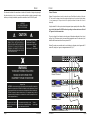
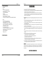
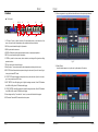
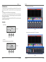
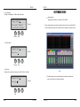
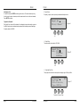
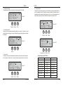
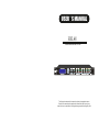
USER ’ S MANUAL
HSL48
Loudspeaker Control System
<BACK
NEXT>
MENU
ENTER
INPUT
PARAMETER
LIMIT
DSC48-HD
BYPASS
OUTPUT
LIMIT
LIMIT
OUTPUT
LIMIT
LIMIT
LIMIT
0dBu
0dBu
0dBu
0dBu
0dBu
0dBu
-48dBu
-48dBu
-48dBu
-48dBu
-48dBu
-48dBu
MUTE
MUTE
MUTE
MUTE
MUTE
MUTE
ESC
DEFAULT 1
DEFAULT 2
DEFAULT 3
The information contained in this manual is subject to change without notice.
No part of this manual may be reproduced or transmitted in any form or by any
means, electronic or mechanical, including photocopying and recording of any kind.
HSL48 Products
Service Information Form
Owner's Name:
Shipping address:
Street:
City:
Zip Code:
Country:
Phone Number:
Email:
Fax Number:
MODEL:
NUMBER:
Place of Purchase:
Name of Dealer:
Full Address:
DATE OF PURCHASE:
SERIAL:
Nature of the problem
(Be sure to describe the conditions that existed when the problem occurred and what
attempts were made to correct it.)
Other equipment in your system
If warranty has expired, payment method:
card number:
Cash
Check
Signature:
Visa
Master
Enclose this form with the defective unit. Do not mail separately.
HSL48
HSL48
Service
LIMITED WARRANTY
This unit has very sophisticated circuitry and should only be serviced by a fully trained technician.
This is why each unit bears the following label:
CAUTION
To prevent electric shock, do not remove covers. No user serviceable parts inside. Refer servicing to a
qualified technician.
Worldwide Service
THE WARRANTY
For a period of one (1) year from the date of delivery to the original purchaser (as shown on the original invoice or
sales receipt), HSL48 warrants to the ORIGINAL OWNER of each new product (provided it was purchased at an
Authorized HSL48 Dealer) that it is free of defects in materials and workmanship and that each product will meet
or exceed all factory published specifications for each respective model. HSL48 agrees to repair or replace (at
its discretion) all defective parts at no charge for labor or materials; subject to following provisions:
WARRANTY VIOLATIONS
HSL48 shall take no responsibility for repair or replacement as specified under this warranty, if the damaged
product has been subject to misuse, accident, neglect or failure to comply with normal maintenance procedures;
or if the serial number has been defaced, altered or removed. Nor will HSL48 accept responsibility for, or
resulting from, improper alterations or unauthorized parts or repairs. This warranty does not cover any damage
to speakers or any other consequential damage resulting from breach of any written or implied warranty.
Service may be obtained from your local authorized service center. To obtain service, simply present
your sales receipt as proof of purchase along with the defective unit to an authorized service center. They
will handle the necessary paperwork and repair. Remember to transport your unit in the original factory
packaging.
DSC48-HD WARRANTY PROVISIONS
HSL48 will remedy any defect, regardless of the reason for failure (except as excluded ) by repair, or
replacement. HSL48 will remedy the defect and ship the product within a reasonable time after receipt of the
defective product at an HSL48Authorized Service Center.
1. When sending an DSC48-HD products to the authorized service center for service, be sure to fill out
the service information form that is enclosed at the end of this manual and include it inside your unit's
shipping pack. Do not send the service information form separately.
TO OBTAIN WARRANTY SERVICE
In the event that an HSL48 product requires service, the Owner must contact HSL48 or an Authorized HSL48
Service Center to receive an R.A.N. ( Return Authorization Number) and instructions on how to return the
product to the HSL48 Authorized Service Center, or to the factory. HSL48 (or its Authorized Service Center) will
initiate corrective repairs upon receipt of the returned product. Please save original carton and all the packing
materials in case shipping is required. All products being returned to the factory or service center for repairs must
be shipped pre-paid.
2. To ensure the safe transportation of your unit to the authorized service center, ship it in an original
factory-packing container.
3. Do not ship the unit in any kind of rack. Ignoring this warning may result in extensive damage to the
unit and the equipment rack. Accessories are not needed. Do not send the instruction manual, cables
and any other hardware.
If the repairs made by HSL48 or the HSL48 Authorized Service Center are not satisfactory, Owner is instructed
to give written notice to HSL48. If the defect or malfunction remains after a reasonable amount of attempts by
HSL48 to remedy the defect or malfunction, the Owner shall then have the option to elect either a refund or
replacement of said HSL48 product free of charge. The refund shall be an amount equal to but not greater than
the actual purchase price, not including any taxes, interest, insurance, closing costs and other finance charges
(minus reasonable depreciation on the product). If a refund is necessary, the Owner must make the defective or
malfunctioning product available to HSL48 free and clear of all liens or other restrictions.
MODIFICTTIONS OF EQUIPMENT
HSL48 reserves the right to modify or change equipment (in whole or part) at any time prior to delivery thereof, in
order to include therein electrical or mechanical improvements deemed appropriate by HSL48 ; but without
incurring any liability to modify or change any equipment previously delivered, or to supply new equipment in
accordance with any earlier specifications.
WEEE Mark
If you want to dispose of this product, do not mix with general
household waste. There are separate collection systems for used
electronic products in accordance with legislation under the WEEE
Directive (Directive 2002/96/EC) and is effective only within the
European Union.
Page 20
User's Manual
DISCLAIMER OF CONSEQUENTIAL AND INCIDENTAL DAMAGES
YOU, THE OWNER, ARE NOT ENTITLED TO RECOVER FROM HSL48 ANY INCIDENTAL DAMAGES
RESULTING FROM ANY DEFECT IN THE HSL48 PRODUCT. THIS INCLUDES ANY DAMAGE TO ANOTHER
PRODUCT OR PRODUCTS RESULTING FROM SUCH A DEFECT.
WARRANTY ALTERATIONS
No person has the authority to enlarge, amend, or modify this Warranty. This Warranty is not extended by the
length of time which the Owner is deprived of the use of product. Repairs and replacement parts provided
pursuant to the Warranty shall carry only the non-expired portion of the Warranty.
THIS STATEMENT OF WARRANTY SUPERSEDES ALL OTHERS CONTAINED IN THIS MANUAL
User's Manual
Page 1
HSL48
The information furnished in this manual does not include all of the details of design and engineering of
this particular product; not does it cover every possible application or situation concerning its usage,
which may occur during the installation, operation or maintenance of said DSC48-HD product.
IMPORTANT
THE PRODUCT REQUIRES
CLASS 2 OUTPUT WIRING.
Shadow ID Numbers
Shadow ID numbers allow extra units to share the same ID and follow the settings of the main
ID. This is useful for larger systems (for example anything above a 4-way stereo system) where
it is only necessary to set up one side of the system, and allow the other unit to track it
identically.
Using the shadow IDs in this way also reduces the apparent system complexity within software. This is
due to the fact that shadow IDs NEVER send back any settings to software and because of this will
NOT appear in the list of connected units.
CAUTION
TO PREVENT ELECTRIC SHOCK, DO NOT
REMOVE TOP OR BOTTOM COVERS. NO
USER SERVICEABLE PARTS INSIDE. REFER
SERVICING TO QUALIFIED SERVICE
PERSONNEL. DISCONNECT POWER CORD
BEFORE REMOVING REAR PANEL COVER
TO ACCESS GAIN SWITCH.
HSL48
Shock Hazard - Do Not Enter
Choc Hasard - N*entrent
Schocke Hazard - Test Nicht
Betrete
Urto Hazard - Do Non Entrano
WARNING
They can be thought of as listening to and acting upon all information addressed to them, but not
replying. Up to 256 shadow units may be connected and assigned the same ID as the main unit, but
remember that the maximum total units on any network is 256.
Shadow ID numbers are accessible when the units interface is configured, and will appear after ID
number 256, starting from 1 again, but designated shadow IDs 2,3,4,5....
<BACK
NEXT>
MENU
ENTER
BYPASS
ESC
PARAMETER
INPUT
LIMIT
DSC48-HD
TO REDUCE THE RISK OF ELECTRIC
SHOCK, DO NOT EXPOSE THIS
EQUIPMENT TO RAIN OR MOISTURE!
DEFAULT 1
DEFAULT 2
OUTPUT
LIMIT
LIMIT
OUTPUT
LIMIT
LIMIT
LIMIT
0dBu
0dBu
0dBu
0dBu
0dBu
0dBu
-48dBu
-48dBu
-48dBu
-48dBu
-48dBu
-48dBu
MUTE
MUTE
MUTE
MUTE
MUTE
MUTE
DEFAULT 3
Remote ID Number=1
<BACK
NEXT>
MENU
ENTER
PARAMETER
INPUT
LIMIT
DSC48-HD
BYPASS
Magnetic Field
CAUTION: Do not locate sensitive high-gain equipment such as preamplifiers or tape decks
directly above or below this unit. Because this amplifier has a high power density, it has a
strong magnetic field which can induce hum into unshielded devices that are located nearby.
This field is strongest just above and below the unit. If an equipment rack is used, we
recommend locating the amplifier(s) at the bottom of the rack and the preamplifier or other
sensitive equipment at the top.
OUTPUT
LIMIT
LIMIT
OUTPUT
LIMIT
LIMIT
LIMIT
0dBu
0dBu
0dBu
0dBu
0dBu
0dBu
-48dBu
-48dBu
-48dBu
-48dBu
-48dBu
-48dBu
MUTE
MUTE
MUTE
MUTE
MUTE
MUTE
ESC
DEFAULT 1
DEFAULT 2
DEFAULT 3
Remote ID Number=2
<BACK
NEXT>
MENU
ENTER
PARAMETER
INPUT
LIMIT
DSC48-HD
BYPASS
OUTPUT
LIMIT
LIMIT
OUTPUT
LIMIT
LIMIT
LIMIT
0dBu
0dBu
0dBu
0dBu
0dBu
0dBu
-48dBu
-48dBu
-48dBu
-48dBu
-48dBu
-48dBu
MUTE
MUTE
MUTE
MUTE
MUTE
MUTE
ESC
DEFAULT 1
DEFAULT 2
DEFAULT 3
Remote ID Number=3
The lightning bolt triangle is
used alert the user to the risk
of electric shock.
The exclamation point triangle is used
to alert the user to important operating
and/or maintenance instructions.
Printed on
recycled paper.
<BACK
NEXT>
MENU
ENTER
BYPASS
ESC
PARAMETER
DEFAULT 1
Page 2
INPUT
LIMIT
DSC48-HD
User's Manual
User's Manual
DEFAULT 2
OUTPUT
LIMIT
LIMIT
OUTPUT
LIMIT
LIMIT
LIMIT
0dBu
0dBu
0dBu
0dBu
0dBu
0dBu
-48dBu
-48dBu
-48dBu
-48dBu
-48dBu
-48dBu
MUTE
MUTE
MUTE
MUTE
MUTE
MUTE
DEFAULT 3
Page 19
HSL48
HSL48
4. Technical Specifications
WARNING
FEATURES:
Inputs
* 4 x XLR IN, electronically balanced
* Input voltage (MAX) 7.55 V / + 20dBu
* 31 bands contant equalizers
* Noisegate
* Input impedance 20 kohms
* Common mode rejection > 70 dB (1kHz)
* AD-conversion 24-bit, Sigma-Delta, 128 times oversampling, linear phase
1. Read all the SAFETY INSTRUCTIONS before using the product.
2. This product must be earthed. If it should malfunction or break down, grounding provides a path of least
resistance for electric current to reduce risk of electric shock.
This product is equipped with a cord having an equipment-grounding conductor and a grounding plug;
The plug must be plugged into an appropriate outlet that is properly installed and earthed in accordance
with all local codes and ordinance.
DANGER- Improper connection of the equipment-grounding conductor can result in a risk of electric
shock.
3. Do not use this product near water - for example, near a bathtub, washbowl, kitchen sink, in wet
basement or near a swimming poor or the like.
4. This product should be located away from heat sources such as radiators, heat registers or other
products that produce heat.
5. The product should be connected to a power supply only of the type described on the operating
instructions or as marked on the product.
6. The power-supply cord of the product should be unplugged from the outlet when left unused for a long
period of time. When unplugging the power-supply cord, do not pull on the cord, but grasp it by the
plug.
7. Care should be taken so that object do not fall and liquid are not spilled into the enclosure through
openings.
8. The product should be serviced by qualified service personnel when:
A. The power-supply cord or the plug has been damaged; or
B. Objects have fallen, or liquid has been spilled into the product; or
C. The product has been exposed to rain; or
D. The product does not appear to operate normally or exhibits a marked change in performance; or
E. The product has been dropped or the enclosure damaged.
9. Do not attempt to service the product beyond that described in the user-maintenance instructions. All
other servicing should be referred to qualified service personnel.
Outputs
* 8 x XLR OUT, electronically balanced
* Output voltage (MAX) 7.55 V / + 20dBu
* 6 bands parametric equalizers, 16 shelving equalizer
* 6 bands Low-Shelving equalizer, Hi-Shelving equalizer
* Output impedance < 100 ohms
* Min. load impedance 600 ohms
* DA-conversion 24-bit, Sigma-Delta, 128 times oversampling
* Frequency response 10 Hz - 30 kHz (- 0.5 dB)
* S/N ratio 110 dB (typical)
* Distortion < 0.01 %
5. Ethernet Connection
WARNING - Do not place objects on the product's power cord or place it in a position where anyone
could trip over, walk on or roll anything over it. Do not allow the product to rest on or to be installed over
power cords of any type. Improper installations of this type create the possibility of fire hazard and/ or
personal injury.
SAVE THESE INSTRUCTIONS
Page 18
User's Manual
User's Manual
Page 3
HSL48
HSL48
9. Choose copy menu to copy data from the edited one to other input/output channel
1. Functions
Front panel
1
23 5 6
<BACK
NEXT>
MENU
ENTER
8
11
INPUT
PARAMETER
LIMIT
HSL48
BYPASS
12
14
OUTPUT
LIMIT
LIMIT
OUTPUT
LIMIT
LIMIT
LIMIT
0dBu
0dBu
0dBu
0dBu
0dBu
0dBu
-48dBu
-48dBu
-48dBu
-48dBu
-48dBu
-48dBu
MUTE
MUTE
MUTE
MUTE
MUTE
MUTE
ESC
DEFAULT 1
4
7
DEFAULT 2
DEFAULT 3
13
9
10
1. LCD Screen: Shows, by default, the name of the last recalled memory on the bottom line of the
screen, Also used to show all parameters as they are edited, and all menu selections.
2. BACK key moves backwards through list of parameters.
3. MENU key activates the main menu .
4. BYPASS will flatten the currently selected parametric sections, or input graphic equalisers.
5. NEXT key moves forward through list of parameters.
6. ENTER key enters the chosen menu, confirms selections, and changes filter types when editing
Fig 2.7
parametric sections.
7. ESC exits menus back to the default screen.
8. Rotary Encoders: Three encoders adjust the relevant parameters as displayed on the screen.
10. Modify Device
choose interface menu to set up the start up information of the device
9. INPUT EDIT buttons illuminate red when pressed, and go into mute mode. if press for I second, it go in
to every input channel EDIT mode.
10. OUTPUT EDIT buttons illuminate red when pressed, and go into mute mode. if press for I second, it
go in to every output channel EDIT mode.
11. INPUT METERS: show dBu clipping point of digital to analogue converters, Green LED illuminates
from -48dBu to 0dBu, yellow LED illuminates the clipping.
12. OUTPUT METERS: show dBu clipping point of digital to analogue converters, Green LED illuminates
from -48dBu to 0dBu, yellow LED illuminates the clipping.
13. Scene change recall key. Press switch for 1 second,processor will load default set program.
14. WIFI antenna. Please add WIFI antenna before turn on power.
Fig 2.8
Page 4
User's Manual
User's Manual
Page 17
HSL48
7. Downoad data to Device. Choose‘Program’menu -----communications then choose the program from PC and which memory you want
to put at the device
HSL48
Rear Panel
2
1
6
3
4
5
*** program 20 to 30 is protected , you can down load data to these 10 memories with
input password .
please get the password from your dealer
8. Upload data from device, firstly the data will be uploaded when connecting to
device.
you can choose‘recall progran from device’from the menu-----communications, and do the same process as Fig 2.6.
1. Power Switch.
2. Power Cord Receptacle, accepted voltage:90~240V 50/60Hz.
3. Ethernet: RJ45 sockets. Used for transmission of remote control data over long distance
or multiple unit applications.
4. Outputs balance XLR connectors.
5. Inputs balanced XLR connectors.
6. Fan.
AES Input
The HSL48 has a full AES implementation built in as standard. This allows the unit to both receive
digital audio directly. The switching of input can be performed independently, and the inclusion of sample
rate converters on the inputs allows the unit to accept sample rates from 32kHz up to 192kHz.
The AES inputs are marked on the rear panel - for channels A & B use input A, and for channels C & D
use input C.
AES/EBU inputs are selected through the AES menu:
Input Sub-Menu Output Selection
Pressing ENTER and then using the first control chooses either Analogue or Digital. Press
ENTER again to confirm Selection.
Fig 2.6
Page 16
User's Manual
User's Manual
Page 5
HSL48
HSL48
5. Setup output channed EQ parameter
2. Preliminary Set-up
1. Design your crossover! To do this, press MENU, and use the BACK or NEXT key to select ‘Xover
sub-menu’and then press ENTER. Use the BACK or NEXT key to select ‘Program’and then press
ENTER.
2. Note that when in a menu, ENTER is always used to confirm selections.
3. Use the EDIT keys on each output channel with the BACK and NEXT keys to select the high pass
filters, low pass filters, parametrics etc. Note that when designing a new crossover, the high and low
pass filters will be set to default values.
4. Use the EDIT keys on each input channel with the BACK and NEX T keys to select the gain, delay
and parametrics available on each input.
3. Operations
1. Input Box Name
I n p u t A : Bo x A
Na m e : B o x A
Figure 1
Fig 2.4
6. Setup route of each channel and delay, HPF, LPF, Limit parameter.
Charactor
Move
2. Input Delay
The maximum available delay of each input is 1000.00mS.
I n p u t A : Bo x A
D e l a y : 0. 0 0 0 m S
0. 0 0 0 0 Me t e r
0. 0 0 0 0 F e e t
Figure 3
MS
Fig 2.5
Page 6
User's Manual
User's Manual
Page 15
HSL48
HSL48
3. Input Polarity
The polarity (or phase) of each output may be switched individually as below.
3. Setup the Input constant EQ
I n p u t A : Bo x A
Figure 4
P o l a r i t y : + No r ma l
- or +
4. Input Gain
The range of the control over the input gain is -40dB to +6dB in 0.1dB steps.
I n p u t A : Bo x A
G a i n 0.
Fig 2.2
Figure 2
DB
4. Setup input channel delay parameter and noisegate
Gain
5. Input Constant EQ
There are 31 bands of constant equalisation available on every input. Changing the filter frequency by
first encoder. Changing the filter gain by second encoder. Confirm filter type by pressing ENTER.
I nput A:
>20Hz
25Hz
3 1 .5 H z
Delay
Time
463.491ms
MS
161.666
Metres
530.400
Feet
29C(90F)
Temp
Temp
Fig 2.3
Page 14
EQ1
0.
0.
0.
: GEQ
0dB
0dB
0dB
Figure 5
Filter type
User's Manual
User's Manual
Page 7
HSL48
HSL48
SOFTWARE GUIDE
6. Input Noisegate
The range of the Noisegate is -120dBu to 0dBu in 1dBu steps.
*** program running
firstly please check the unit is connect to PC by RS485
I n p u t A : Bo x A
Noisegate: Enable
Threshold: -120dBu
Charactor
Figure 6
1. Choose connecting from menu, select comport by clicking ok, You can use Search ID to
find the connect devices also you can enter the unit ID manually, It can save your time.
Move
7. Output Box Name
O u t p u t 1 : Bo x 1
Na m e : B o x 1
Charactor
Figure 7
Move
8. Output Gain
The range of the control over the output gain is -40dB to +15dB in 0.1dB steps.
Fig 2.1
2. The Data currently use the unit will upload to Pc when they connected the
O u t p u t 1 : Bo x 1
G a i n 0.
dB
screen of unit will shows “computer connecting”
Figure 8
Gain
Page 8
User's Manual
User's Manual
Page 13
HSL48
Unlocking the Unit
To unlock the unit press ENTER and then type the code in. This can be entered by using
the first control to select a character, and the second control to move to the next character.
Press ENTER to confirm.
HSL48
9. Output Polarity
The polarity (or phase) of each output may be switched individually as below.
O u t p u t 1 : Bo x 1
Forgotten the Password?
Don’t panic! Your unit can still be unlocked. In an attempt to improve the security system on
the HSL48, and prevent a standard master password from becoming common knowledge,
the super password is 666666.
P o l a r i t y : + No r ma l
Figure 9
- or +
10. Output Delay
The maximum delay of each output is 1000.00mS.
Output 1 :
D e l a y : 0.
0.
0.
Bo x 1
000 mS
0 0 0 0 Me t e r
0000Feet
Figure 10
MS
11. Output High Pass Filter
The high pass crossover filter on each output has a frequency range of 10Hz up to 30kHz .
O u t p u t 1 : Bo x 1
HPF
Fre q: 10Hz
Filter:Link-Riley
Slope: 12dB/0ct
Figure 11
Frequency Filter type Slope
Page 12
User's Manual
User's Manual
Page 9
HSL48
12. Output Low Pass Filter
The low pass crossover filter on each output has a frequency range of 10Hz to 30kHz.
O u t p u t 1 : Bo x 1
LPF
Fre q: 10Hz
Filter:Link-Riley
Slope: 12dB/0ct
Frequency Filter type
HSL48
14. Output Compressor
The clip limiter on each output is designed to sit at a threshold just above the standard limiter and
has a look ahead attack so that its threshold can never be exceeded. The release time can be
automatically linked to the high pass filter frequency, so that it is set to a value appropriate for the
outputs frequency range. If this feature is enabled, the display will show compressor: Auto.
Figure 12
O u t p u t 1 : Bo x 1
Mo d e : c o m p re s s o r
T h r e s h o l d : + 2 0. 0 d B u
A t t : 0. 3 m s
Re l : 8 x
Slope
13. Output Parametric EQ
There are six bands of parametric equalization available on every output4. The behaviour of each
individual band can be changed to a variety of different filter shapes, including high and low shelves,
and bandpass.
Output 1 :
E Q 1 : PE Q
Fre q: 10Hz
G a i n 0. 0 d B
B a n d w i d t h : 0. 0 5 0 c t
Threshold
Attack
Release
O u t p u t 1 : Bo x 1
C o m p re s s o r : Ma nu a l
C l i p l i m : 2. 0dB
A b ove
Ratio: 1 : 1
Figure 13
Figure 14-1
Figure 14-2
EQ type
Compressor Type Threshold
14. Output Limiter
The limiter on each output has adjustable attack and threshold, with a release time that is selectable
to be a multiplier of the attack time. For example, as shown below, the attack time is 0.3mS and
O u t p u t 1 : Bo x 1
MO d e : L i m i t
T h r e s h o l d : + 2 0. 0 d B u
A t t : 0. 3 m s
Re l : 8 x
Threshold
Page 10
Attack
Auto mode frequency time ATT/RES list
Figure 14
Release
User's Manual
Ratio
User's Manual
High Pass Filter
Auto Attack Time
Release Time
<10Hz - 31Hz
45mS
x16 (720mS)
31Hz - 63Hz
16mS
x16 (256mS)
63Hz - 125Hz
8mS
x16 (128mS)
125Hz - 250Hz
4mS
x16 (64mS)
250Hz - 500Hz
2mS
x16 (32mS)
500Hz - 1kHz
1mS
x16 (16mS)
1kHz - 2kHz
0.5mS
x16 (8mS)
2kHz - 32kHz
0.3mS
x16 (4mS)
Page 11