1
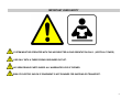
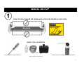
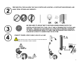
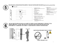
READ MANUAL ( IMPORTANT INFO !!! )
TEST CONTENT ON THE USER CD FIRST
PRACTICE USING BEFORE ANY DEMO
INFORMATION / QUESTIONS / SETUP:
WWW.IO2TECHNOLOGY.COM/L90.HTML
[email protected]
2
user manual
heliodisplay
L90
2011-1
Unauthorized modifications to the hardware or software, including but not limited to tampering with logos or insignia, or opening non-user-serviceable parts of the display, will immediately and
permanently void all warranties, to the extent permissible under California law. The contents of this manual are subject to change without notice. Copying of this manual, either in part or in it’s entirety
is forbidden.
3
IMPORTANT USER SAFETY
SYSTEM MUST BE OPERATED WITH THE AIR DIRECTED IN ONE ORIENTATION ONLY. (VERTICAL TOWER)
USE ONLY WITH A THREE-PRONG GROUNDED OUTLET.
NO SERVICEABLE PARTS INSIDE. ALL WARRANTIES VOID IF OPENED.
RISK OF ELECTRIC SHOCK IF EQUIPMENT IS NOT DRAINED FOR SHIPPING OR TRANSPORT.
4
BASIC SETUP
OPEN THE CRATE. REMOVE THE TOWER AND PLACE ON THE GROUND IN A SAFE AREA
USEFUL TOOLS: SUGGESTED
OR
FLAT SCREWDRIVER: TO ADJUST SETTING “B”
CLEAN ANY BUILDUP OF CONDENSATION ON HONEYCOMB GRILL
Water container, or (IO2 Accessory)
5
PREPARATION. FIND AN AREA THAT HAS CONTROLLED LIGHTING, A CONTRAST BACKGROUND, AND
AWAY FROM STRONG AIR CURRENTS
BE PREPARED TO SPEND TIME TO BECOME KNOWELDGEABLE WITH THE
SYSTEM. AFTER PRACTICE, IT WILL ONLY TAKE A FEW MINUTES TO SETUP AND
OPERATE. TURNING ON A HELIODISPLAY IS STRAIGHT FORWARD, HOWEVER
TO CREATE IMPRESSIVE RESULTS TAKES TIME, EXPERIENCE AND CREATIVITY.
PLEASE BE PATIENT TO UNDERSTAND THE SYSTEM.
CONNECT POWER, VIDEO CABLE, & BLUE H20 LINE
FIRST USE SET THE PC, MAC OR LAPTOP TO A BLACK DESKTOP
AND RUN ONE OF THE SAMPLE VIDEO CONTENT.
6
PROJECTOR IN A REAR-PROJECTION SETUP, TURN ON THE PROJECTOR SWITCH (test level at eye-level first)
USE ANY WHITE SURFACE (SUCH AS A SHEET OF PAPER) PLACED TEMPORARILY IN FRONT OF THE
HONEYCOMB GRILL TO TEST THE FOCUS OF THE PROJECTOR. PROJECTOR CAN BE PLACED
APROXIMATELY 1.8M BEHIND THE TOWER. IT CAN BE MOVED CLOSER OR FURTHER AWAY.
VERIFY EXHAUST IS UP
7
TURN SWITCH TO POSITION“1” WAIT APROXIMATELY 2 MINUTES FOR THE
FIRST TIME. (ON FUTURE BOOT-UPS, THIS WILL ONLY TAKE ABOUT 2 SECONDS)
Setting II : requires 3VDC to 12VDC applied to the 2pin connector at the top lid. Upon supplying power, the system will
turn on, by removing power, the system will shut down. Any controller can be used, or a 9VDC battery.
HOW DOES THIS WORK? HELIODISPLAY USES MAINLY AIR TO CREATE THE MEDIUM. THERE ARE
THREE SEPARATE AIR STREAMS AND A SINGULAR ONE WITH A SMALL AMOUNT OF MOISTURE & AIR.
DO NOT PUT HOT WATER INTO THE HELIO.
THE WATER COOLS THE SYSTEM. PLACING HOT
WATER OR BOILING WATER WILL OVERHEAT THE
MODULE AND MAY CAUSE PERMANENT DAMAGE
ADJUST THE SETTINGS BY CONTROLING BOTH “A” AND “B” KNOBS LOCATED ON TOP. NOTE OF THE
SETTINGS ARE TOO HIGH OR TOO LOW GAPS IN THE AIR MEDIUM CAN OCCUR. SEE TROUBLESHOOTING.
NOTE THE CONTROL “B” IS ON THE TOP/SIDE
8
TO DRAIN OR TRANSPORT, PLACE THE TOWER A SLIGHTLY ABOVE GROUND, AND PLUG IN THE
DRAIN HOSE AND OTHER END INTO A BUCKET. YOU CAN NOW TILT AND TRANSPORT .
ADVANCED SETUP (RECOMMEND READING)
Heliodisplay is a two-component system The projector module is to be placed in a rear-projector orientation and the heliodisplay
base unit with the grill pointed sideways unless ordered in another configuration. Orienting the equipment in an incorrect position
can damage the equipment or cause user harm.
Heliodisplay is a unique system that will require some time to learn and optimize for your setup. Please read this manual carefully as it outlines important items for setting up and using the
equipment properly. You will first need to do some prep work to get the configuration setup, including setting your laptop or PC desktop background set to black.
ALWAYS DRAIN THE HELIO IF TRANSPORTING!
SETUP / ENVIRONMENT
9
Like any video projector, or display contrast is a function of human perception, the contrast between the darkest and brightest
areas. Since the Heliodisplay projects images into air, images have to compete with bright backgrounds, even lighting from behind-something that does not apply to conventional displays where the background is always black and opaque as it is contained within
a physical display. As a result, controlled ambient lighting, but most importantly, a contrast in the background will help improve
contrast.
CHOSING THE RIGHT CONTENT
While Heliodisplay can display almost any image or video, it is better at displaying IMPACTFUL content; therefore certain guidelines contained herein should serve as a foundation for generating
content for improving the results. A few examples supplied in the Heliodisplay User CD include content samples should be tested. Below are a few guidelines:
1. A black background for the content is a must. Reset your computer desktop to black if using a computer.
2. High contrast foreground images. Use bright simple colors, whites, greens, etc. ONLY TEST CONTENT WITH THE SUPPLIED CD
3. Dynamic moving images
4. Preferably do not fill up entire screen area with content. Leave a substantial black border that will make the images 'pop'.
5. Rotate the projector 90 degrees for portrait style aspect ratio.
THE PROJECTION
Heliodisplay system is designed for front viewing only with a rear-projection setup. Locate the projector behind either below or above the height of the person. Try to maintain a projection beam so
that the light is slightly above or below the observer’s eyes. Too high or low of an angle and the image will appear wavy or dim. Situating the base unit around chest level will also improve the light
path by allowing the beam to project over the viewers head and out of the eye. Try various set ups and locations. It may take some practice to find a geometry that works. An on-axis projection
source with the viewer will provide the brightest and crispest image. Lowering the resolution on the laptop will increase the image size.
Decrease the computer resolution and the image
size will increase in size.
Setting of 50% brightness & 60% contrast will generate the optimal image.
10
PROP UP PROJECTOR SIDEWAYS: NOTE THAT THE ASPECT RATIO WILL BE TALLER THAN
WIDER.
IMPORTANT: Position system so that projection beam is as close to on-axis as possible without direct starring into beam
MAINTAIN PROJECTOR POINTING +/- 30 DEG AT VIEWER
(LARGER ANGLE WILL DECREASE PICTURE QUALITY, STABILITY, LESS BRIGHT,LESS CLEAR)
Never block any air to or from the projector.
TURNING ON
DUTY CYCLE: The Heliodisplay is capable of daily use 8-10 hours a day use similar to
a business style projector. No serious damage will occur if the system runs longer that this
amount of time, but this may require using a compressed air can to temporarily clean out the
central part of the honeycomb) as high humidity environments and long run times may create
condensation that needs to evaporate overnight or be cleaned. However, if the density setting is
set to the default setting operating using the existing air, little to no condensation will occur, and
the system can run much longer. This air-based setting is also invisible and the preferred
operating setting.
ADJUSTING THE SETTINGS
The Heliodisplay has been optimized prior to shipping, but as an air-based system it responds to the ambient air. As a result, during shipping, and under some conditions in transit (hot and cold
extremes), condensation can build up inside the equipment temporarily. In order to remove this build up, you can direct a pressurized air can downward into the central portion of the honeycomb
grill (where the screen comes out) for about 3 seconds and that will dislodge any build-up. If over time of operation (a day of use), you find there to be too many lines in the picture, you may need
to repeat this operation. This means the density setting is too high and fan speed too slow. Increase the fan speed to or decrease the density to prevent this from repeating.
11
The laws of physics dictate that no flow can be laminar (completely uniform and linear) for a certain distance,
therefore the Heliodisplay image will never be as completely stable as a conventional physical monitor as it is
being projected onto constantly moving air. If you feel you need to make any adjustments to the Heliodisplay
screen, the settings can be adjusted for fine tuning by rotating the adjustment knob. This will change the
various airspeeds and screen settings until you find a setting that is suitable. The density setting should be set
where the screen is barely visible from two to three meters from the image.
Due to the sensitive nature of airflow being affected by environmental conditions you may notice that upon first turning on the equipment that the screen may not seem crisp or clear at first. Do not
be alarmed, as the settings were set correctly at the factory before shipping but due to variations in voltage, power frequency, humidity and ambient temperature it is very likely that the settings will
need to be adjusted. (TURN THE ADJUSTMENT KNOB). You will do this after you have set up the equipment.
•
If the ambient humidity is high, or the density setting is set too high, or exceeding the advised operating time may require using an air can to clean the honeycomb. You can also reduce
the density setting (the knob adjacent to the on/off button) to compensate.
STORING
TO DRAIN: Tilt the base unit and connect the drain hose. Make sure the unit is COMPLETELY DRY. Tilting the tower and placing it OFF THE GROUND will remove all the
remaining water. Allow water to pour into a bucket below as gravity will drain the remaining.
If you need to transport your Heliodisplay so that you require to tilt it more than 30 degrees you should drain the tank. This is to prevent any leaking. Tilting it grater than this amount may
cause an overflow. If you plan to use the Heliodisplay occasionally you can keep the tank filled without any damage. If you do not plan to use the equipment for more than a month at a time, it
may be a good idea to drain the chamber. A bucket or any receptacle can be used to collect the drained condensate prior to moving the Heliodisplay.
TO OPERATE FOR INSTALLATIONS
Enable the remote switch II setting to control remotely and connect the tower to
the heliodisplay 5 gallon external tank accessory. The heliodisplay external tank contains a permanent hook up line to connect permanently. However it is recommended to shut down the
equipment at night when not in use using the remote setting II on the powerswitch. If the external tank is not connected to an external line, the tank will operate for a few days of use under normal
conditions without refilling (for rentals etc)
TROUBLESHOOTING GUIDE
12
Honeycomb Grill has a dent.
SOLUTION :Only dents within the
central portion of the honeycomb will
affect the image. Using a set of
tweezers, GENTLY try to bend the
aluminum back into shape.
The screen does not come up, but the fans
are on.
SOLUTION :Check that the pump is
pumping water. Note that the pump will not
turn on continuously. Is the water room
temp or colder?
Try connecting and disconnecting the hoses to tes
From time, to time, the pump may need to be
manually primed, especially if the unit is not being
used regularly. Try disconnecting the hoses and re
attaching.
If the unit overfills, or starts to leak after
powering for a few minutes, check the
float sensor. The white float sensors
may be jammed during transport and
causing an overfill. If leaking is
immediate, a seal may be broken at the
bottom.
SOLUTION : Open side bottom
access panel. Verify both white floats
move freely. If damaged, order part
“FLT”
Find location of leak and plug up with
silicon. Let dry overnight.
If there is a dense cloud of water vapor
coming out from the small fan above the
expansion tank.
SOLUTION : The yellow setting was
set too low! Increase the fan setting
by turning the yellow knob (Control
B). Setting too low will not engage the
fan. If still not working, drain, place unit
horizontal and check the connector at
the bottom.
SOLUTION Is the water tank empty?
Pump may be pumping air. If pump
is not working Check the pump
replace or service existing pump.
(Servicing: open the four small metal
screws on the pump head and
cleaning out the internal diaphragm
before reattaching.)
SOLUTION :Adjust the settings. Increase
the main fans. If this does not help, then
use an air can on center part of honeycomb
to unclog honeycomb. Your airflow setting
may be too low AND/OR the density set too
high.
The settings to the heliodisplay need to
be set so that the airflow is high and the
density is set low. If the density is high
and the airflow low, the honeycomb can
clog up over time, but this can be
temporarily fixed with an aircan. The
permanent solution is increase the fan
speed and decrease the density.
SOLUTION : You may need to clean the
titanium disks (see below) with a Q-tip (no
detergents or solvents), if worn out, the
replace the disks. (supplied). Always
make sure there is no water inside the
tank when unscrewing the disks, and
tighten firmly without over tightening.
See Maintenance.
If the unit does not turn on then check the fuse.
a
Small flathead screwdriver to open the compart
There are two fuses, one in operation, and the o
as a replacement (5x20mm 240V, 3.15A). If the
is blown then there is something not working
correctly,
and you should stop using the equipment and
contact IO2 immediately.
13
POSSIBLE PROBLEMS & SOLUTIONS
#1. Leak 1 (OverFlow): If the unit starts to leak water after operating for a few minutes, check that the white sensor moves freely inside the side access panel. Replacement part
“FLT” for 2011 replaces existing sensors. Covered under warranty. No charge for parts. Parts can be ordered here www.io2technology.com/L90.html
#2. Leak 2 (Seal): If the unit starts to leak immediately, check the side pump opening and see if the pump is properly connected. If the leak originates from the bottom it means a seal
on the bottom may have been damaged. Using silicon and drying 24 hours can seal any crack that may have occurred.
#3. Screen stops working randomly: Tank filled up, but no screen 1) Drain the unit, open the bottom access panel. 2) Check visually every white disk. Any disk that look
damaged, may need to be replaced. NOTE: THE RING FROM EACH DISK MUST BE PROPERLY TIGHTENED. WATER CAN ENTER AND SHORT CIRCUIT OTHERWISE. You may need to
clean underneath the disk for any corrosion if that occurs. ANY CORROSION OR A BLACK CRACK IN THE DISK MEANS THE DISK RING WAS NOT PROPELY TIGHTENED!!! (Tighten firm,
but not too forceful). DISKS LAST FOR ABOUT 6-18 MONTHS. IF YOU ARE REPLACING THEM BEFORE THAT, SOMETHING IS NOT CORRECT (water dirty, or not tightened)
******** ANY CORROSION UNDER THE DISK INDICATED THAT THE RING IS NOT TIGHTENED. THERE SHOULD NEVER BE ANY CORROSION UNDER THE DISK.
#4. Mist Cloud from bottom of grill (Bottom fan); Check that the bottom fan is not damaged. You can drain the unit and while empty power up the unit. Check if there is 13V on the
bottom fan connector. If there is, the fan may have been damaged if the unit as dragged on the ground, or not properly drained. If there is no voltage, or a voltage reading under 5v then the mini
power supply units may need to be replaced with part #PWMI. Covered under warranty. No charge for parts. Parts can be ordered here www.io2technology.com/L90.html
14
CONTINUED ON PAGE 2
#5. Big horizontal gaps in the image: Reduce the density setting, and increase control A (top knob). If it is at maximum, do not try
to move it any more. Too much ambient humidity is causing a build up or moisture inside the grill along the locations in which there is a gap. This
can be cleaned temporarily by running an aircan along the center area.
#6. Tank not filling up (pump not working) Is the pump jammed into the portal? Are the hoses kinked? Is there a
hole in the hose (if the helio crushed the blue hose, a small opening in the water line can cause air to leak in and the pump will
pump air, not water). Similarly, if the line is kinked, water will not flow. If the hose is not properly seated in the pump the pump will
pump air and not the water. Check that the connection of the hose to the pump is firm. Note the pump will not be operational the
entire time, and only turns on when the inside level is low.
First check the pump by removing the IN PORT of the hose pump and see if the pump moves/operates. If it does, there may be
dirt inside the pump. You can either try to open the pump by removing the four screws and CAREFULLY put the pump back
together or replace it with a new one. Pumps will last between 6-12 months of operation so if there is any premature failure you
should check why.
If the pump is still not working, but seems to be in good condition, then perform the following. Drain the unit, open the side access
panel and check to see if the white sensors move freely. Turn on the unit (with the access panel open, and no water) and try to see
if the pump operates when you flip the white sensors up and down. If the pump still does not work, check the voltage on the 2-pin
connector by the input of the pump. A replacement float sensor can be ordered.
MAINTENANCE & SERVICING
INFORMATION: http://www.io2technology.com/L90.html
We recommend that the heliodisplay be checked regularly as preventive maintenance. This will also help in avoiding any of the potential issues listed in the troubleshooting guide. Since installation
conditions, water quality, humidity, temperature and duty cycle all effect the replacement cycle for parts, such as pumps and filters, the following guide should serve as reference only as it may be that they
last many times longer or shorter than stated here. Typically though, pumps and filters should last for about 6-24 months depending on use, but the pump can fail for shorter periods if used under more
strenuous conditions, or have the pump lasting for five years or longer without replacing.
It is good to check the cleanliness of the fans. The MTBF for the fans are 20,000 Hours, but if moisture or dust collects on them, their life may be shortened.
It is also recommended that the honeycomb grill be checked every 60-90 days for any collection of moisture residue.
15
Open up the ultrasonic tank. The smoked gray plastic window with the glowing red light is where the particle cloud is generated. Check to see that the disks are like-new and uniform in color (white or
gold color). If they are not, use a Q-tip and GENTLY wipe down the surface a few times. DO NOT rub hard on the surface and wear out the disk. If the disks are worn out, then DISCONNECT POWER to
the heliodisplay, and remove any water that is on top of the ultrasonic disks. IT MUST BE DRY BEFORE PERFORMING any replacement.
OPTIONAL EQUIPMENT
ORDER
EXTERNAL TANK 5 GAL.
EXTRA ULTRASONIC DISK
http://www.io2technology.com/L90.html
BAFFLED PROJECTION 4500 LUMEN
EXTRA PUMP
EXTRA FUSE
EXTRA FILTER
IO2 PROVIDES NO-COST SERVICING AND REPAIR ON PARTS OR LABOR FOR ON ANY HELIODISPLAY FOR 3
YEARS ON PARTS AND LABOR FROM DATE OF PURCHASE.
SOME EXCEPTIONS APPLY SUCH AS IO2 DOES NOT PAY FOR SHIPPING OR COVER ANY SERVICING FOR ABUSED EQUIPMENT. IF YOU WISH TO HAVE YOUR
EQUIPMENT REPAIRED OR SERVICED FREE OF CHARGE, GO TO WWW.IO2TECHNOLOGY.COM/L90.html, AND FILL OUT THE RMA FORM (ONLINE) AND
SEND THE EQUIPMENT PRE-PAID FOLLOWING THE DIRECTIONS CAREFULLY.
IO2 Technology LLC (USA), (hereafter IO2) warrants this product to be free from defects in material
and workmanship under the following terms.
HOW LONG IS THE WARRANTY
IO2 Technology products (model dependant) are covered by a THREE YEARS (3) year limited parts
and labor warranty from the date of the first customer purchase.
WHO IS PROTECTED
This warranty may be enforced only by the first purchaser, and is not transferable.
WHAT IS COVERED AND WHAT IS NOT COVERED
IO2 COVERs ALL INTERNAL PARTS ON THE BASE MODULE (THE SCREEN MODULE) FOR UP
TO THREE YEARS. This covers the hardware and software, and ANY malfunction to the system.
This warranty excludes shipping costs to and from IO2’s repair locations (USA), or any visible abuse
or damage to the hardware.
Except as specified below, this warranty covers all defects in material or workmanship in this
product.
IO2’s LIABILITY FOR ANY DEFECTIVE PRODUCT IS LIMITED TO THE REPAIR OR
REPLACEMENT OF DEFECTIVE PARTS AT IO2's OPTION. REPLACEMENT PARTS MAY BE
NEW OR RECONDITIONED PRODUCTS. The following are not covered by the limited warranty and
IO2 shall not be liable for:
1.
Any product which is not distributed by IO2.
2.
Any product on which the label or serial number has been defaced, modified or removed.
3.
Any indication of opening the enclosure to gain access to the products interior enclosure.
1.
2.
3.
4.
5.
6.
Removal or installation charges.
Damage caused by abuse to the product (i.e. dented case).
Payment of shipping and related charges incurred in returning the product for warranty repair.
Product use beyond the operating requirements.
Damage to projector due to water intrusion, or bulb replacement.
Projector bulb.
Customers are made aware that product performance is influenced by environmental conditions, such as but not limited to,
temperature, humidity, ambient lighting, system configuration, video content, and operator control, among other factors. Review
the operating manual for further information. While the product is considered to be compatible with many systems (DVD, PC
computer etc), the specific functional implementation by the customers of the product may vary. The suitability of a product for a
specific purpose or application must be determined by the customer and is not warranted by IO2.
HOW YOU CAN GET WARRANTY SERVICE
1.
To obtain service on your product, consult IO2 or the dealer from whom you purchased the product.
2.
Whenever warranty service is required, send a written list of the problems along with the hardware.
3.
All products returned to IO2 for service MUST HAVE AN APPROVED RETURNED MERCHANDISE APPROVAL
(RMA). To receive approval or for the name of the nearest IO2 authorized service center, email IO2 at
[email protected]
4.
It shall be your obligation and expense to ship the product, freight prepaid, or to deliver it to a IO2 authorized
service center, in either the original package or a similar package affording an equal degree of protection during shipping.
5.
In the event a product is returned to IO2 for warranty service, and it is determined that there is no product defect or
16
4.
Any modification to the product that is not part of the original product.
5.
The product is designed to operate in a fixed installation setting in order to prevent tilting
or rotating during use. Any direct or indirect damage caused by rotating is not covered.
6.
Service required as a result of third party components.
7.
Normal decrease in lamp light (projector bulb) output over time.
8.
Damage, deterioration or malfunction resulting from:
a.
Accident, misuse, abuse, neglect, improper ventilation, fire, dust, smoke, water, lightning,
or other acts of nature, unauthorized product modification, and failure to follow instructions supplied
with the device.
b.
Repair or attempted repair by anyone other than an IO2 authorized service center.
c.
Any shipment of the product (claims must be presented to
the carrier).
d.
Removal of an IO2 installation of the product.
e.
Any other cause which does not relate to a product defect.
f.
Use of the product beyond normal operating conditions.
9.
All serviceable parts are accessible.
WHAT IO2 WILL PAY FOR
IO2 will pay for labor and material expenses all covered items, including but not limited to filters,
pumps, fans, tubing, wiring, workmanship or other parts found to be defective, but IO2 will not pay for
the following
that the product condition is not covered by this limited warranty, no diagnostic or service fee will be charged to the customer.
LIMITATION OF IMPLIED WARRANTIES
EXCEPT AS EXPRESSLY SET FORTH IN THIS LIMITED WARRANTY, IO2 MAKES NO OTHER WARRANTIES,
EXPRESS OR IMPLIED, INCLUDING BUT NOT LIMITED TO ANY IMPLIED WARRANTIES OR CONDITIONS OF
MERCHANTABILITY AND FITNESS FOR A PARTICULAR PURPOSE. ANY IMPLIED WARRAN¬TIES THAT MAY BE
IMPOSED BY LAW ARE LIMITED TO THE TERMS AND DURATION OF THIS LIMITED WARRANTY.
EXCLUSION OF DAMAGES
IO2’s LIABILITY FOR ANY DEFECTIVE PRODUCT IS LIMITED TO THE REPAIR OR REPLACEMENT OF THE
DEFECTIVE PARTS OR WORKMANSHIP AT IO2’s OPTION. IO2’s SHALL NOT BE LIABLE FOR:
1.
DAMAGE TO OTHER PROPERTY CAUSED BY ANY DEFECTS IN THIS PRODUCT, DAMAGES BASED
UPON INCONVE¬NIENCE, LOSS OF USE OF THE PRODUCT, LOSS OF TIME, COMMERCIAL LOSS; OR
2.
ANY OTHER DAMAGES, WHETHER INCIDENTAL, CONSE-QUENTIAL OR OTHERWISE.
3.
DAMAGE OR HARM TO THE PRODUCT OR PERSONS CAUSED BY MISUSE OR IMPROPER SETUP
HOW STATE LAW RELATES TO THE WARRANTY
SOME STATES DO NOT ALLOW LIMITATIONS ON HOW LONG AN IMPLIED WARRANTY LASTS AND/OR DO NOT
ALLOW THE EXCLUSION OR LIMITATION OF INCIDENTAL OR CONSEQUEN¬TIAL DAMAGES, SO THE ABOVE
LIMITATIONS AND EXCLU¬SIONS MAY NOT APPLY TO YOU. THIS LIMITED WARRANTY GIVES YOU SPECIFIC
RIGHTS, AND YOU MAY HAVE OTHER RIGHTS WHICH VARY FROM STATE TO STATE.
FOR MORE INFORMATION, CONTACT:
IO2 Technology LLC
851 Cherry Ave 27/505,
San Bruno CA 94066 www.io2technology.com
Certifications and Declarations
WEEE Statement
(Waste Electrical and Electronic Equipment)
The WEEE directive places an obligation on EU-based manufacturers, distributors, retailers and importers to take-back electronics products at the end of their useful life. A sister Directive,
ROHS (Restriction of Hazardous Substances) complements the WEEE Directive by banning the presence of specific hazardous substances in the products at the design phase. The WEEE
Directive covers all IO2 products imported into the EU as of January 1, 2008. EU-based manufacturers, distributors, retailers and importers are obliged to finance the costs of recovery from
municipal collection points, reuse, and recycling of specified percentages per the WEEE requirements.
Instructions for Disposal of WEEE by Users in the European Union. The symbol shown below is on the product or on its packaging, which indicates that this product must not be disposed of
with other waste. Instead, it is the user’s responsibility to dispose of their waste equipment by handing it over to a designated collection point for the recycling of waste electrical and electronic
equipment. The separate collection and recycling of your waste equipment at the time of disposal will help to conserve natural resources and ensure that it is recycled in a manner that
protects human health and the environment. For more information about where you can drop off your waste equipment for recycling, please contact your local city office, your household
waste disposal service or where you purchased the product.
Note that each component (power supply, base unit, projection module) carry varying certifications and declarations posted on the label on each part. Some components may carry different
or none of the certifications as other parts in the total system.
17
END OF MANUAL
18