1
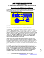
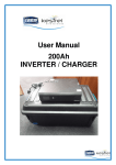
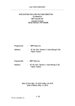
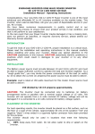
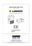
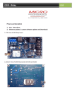
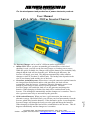
JSM POWER CONVERTION CC REG NO. 2004/119440/23 For the development and production of power electronic products 13 Premier Park, 32A Fabriekstraat,Kuilsrivier, Cape Town, 7580 Tel/Fax : +27(0)86 173 2767, Email : [email protected] , Web: www.jsmpower.co.za Page The Inverter/Charger can be used in 3 different modes (applications). Offline UPS: Where you have an unstable grid connection or where load shedding is used, you will use the Inverter/Charger as a backup power source. While the grid is available, the Charger will keep the batteries (not included) fully charged and the load will run from the grid. When the grid falls away, the Inverter will supply your load. This happens automatically with a seamless changeover time of less than 12 milliseconds. The backup time depends on the size of your battery bank and the size of the load. Generator Assisted Inverter: Where there is no grid connection and the batteries are charged from Solar Panels and/or wind generators, the load will run permanently from the Inverter. Sometimes when the alternative power is not enough it is necessary to run a diesel or petrol generator. Then the Inverter/Charger will switch the load over to the generator and charge the batteries. When charging is finished, the load will be switched back to the Inverter. This all happens automatically and the changeover is seamless. There is also a generator start relay to start and stop the generator. Grid Assisted Inverter: When you have a grid connection, but want to use alternative energy, like Solar Panels, you will run your load permanently from the Inverter, which runs from the batteries. If the alternative power is not enough the Inverter/Charger will change the load over to the grid and charge the batteries. When charging is finished the load will be switched back to the Inverter. This all happens automatically and the changeover is seamless. 1 User Manual 6 kVA, 36Vdc – 230Vac Inverter/Charger JSM POWER CONVERTION CC REG NO. 2004/119440/23 For the development and production of power electronic products Table of Contents Page 2 Inverter Specifications ................................................................................................. 3 Charger Specifications................................................................................................. 3 General Specifications ................................................................................................. 3 Protection Features ...................................................................................................... 3 Other features............................................................................................................... 4 Installation .................................................................................................................... 4 Battery Connection .................................................................................................... 4 Load Connection ........................................................................................................ 5 Mains/Generator Connection ..................................................................................... 5 Generator Start ........................................................................................................... 5 Switching on ................................................................................................................. 5 Comprehensive LED Display and Buzzer ................................................................. 6 Keypad and LCD Display ........................................................................................... 8 Viewable parameters .................................................................................................. 8 Equalize Cycle .............................................................................................................. 9 Settable Parameter..................................................................................................... 10 Float Voltage ............................................................................................................ 10 Float Time ................................................................................................................ 10 Absorb Voltage ........................................................................................................ 10 Absorb Time ............................................................................................................ 11 Equalize Voltage ...................................................................................................... 11 Equalize Time .......................................................................................................... 11 Battery Low Voltage ................................................................................................ 11 Battery Low Time .................................................................................................... 11 Battery Reconnect Voltage ...................................................................................... 11 Battery Reconnect Time .......................................................................................... 12 Refloat Voltage ........................................................................................................ 12 Generator Mode ....................................................................................................... 12 AC IN OFF Voltage ................................................................................................. 12 AC IN OFF Delay .................................................................................................... 13 AC IN ON Voltage .................................................................................................. 13 AC IN ON Delay ..................................................................................................... 13 Generator Warmup Delay ........................................................................................ 13 AC Input Lower Limit ............................................................................................. 13 AC Input Upper Limit .............................................................................................. 13 AC Input Maximum Current .................................................................................... 14 AC INPUT Source? ................................................................................................. 14 Output Voltage ......................................................................................................... 14 Password to Set Calibration ..................................................................................... 14 13 Premier Park, 32A Fabriekstraat,Kuilsrivier, Cape Town, 7580 Tel/Fax : +27(0)86 173 2767, Email : [email protected] , Web: www.jsmpower.co.za JSM POWER CONVERTION CC REG NO. 2004/119440/23 For the development and production of power electronic products Inverter Specifications Nominal Battery Voltage Input Voltage Range Operating Voltage Range Output Voltage Waveform Total Harmonic Distortion Output Power for 30 min @25°C Continuous Power @25°C Maximum Output Power Efficiency Power Consumption – idle : : : : : : : : : : : 36 Vdc 30 – 70 Vdc 30 – 50 Vdc 220 – 230 Vac Settable, 50 Hz Pure Sine Wave < 3% 6000 VA 5000 VA 18 kVA for 5 s >90% 34W Charger Specifications Input Voltage Input Frequency Input Current Charging Current Charging type : : : : : 180Vac – 270Vac 45Hz – 55Hz 15 Amps ac 70 Amps 3 Stage General Specifications Enclosure Dimensions (w x h x d) Feet Weight : : : : Powder coated mild steel 630mm x 320mm x 350mm Rubber 53 kg Over Voltage Protection Under Voltage Protection Short Circuit Protection Over Temperature Protection : : : : : : : : Electronic DC Circuit Breaker AC Input Circuit Breaker AC Output Circuit Breaker 66 V Settable (30.0V – 34.5V) 80 A >85°C 13 Premier Park, 32A Fabriekstraat,Kuilsrivier, Cape Town, 7580 Tel/Fax : +27(0)86 173 2767, Email : [email protected] , Web: www.jsmpower.co.za Page Over Load Protection 3 Protection Features JSM POWER CONVERTION CC REG NO. 2004/119440/23 For the development and production of power electronic products Other features Zero spark connection Cooling Battery Connection AC Output Connection (Load) AC Input Connection (Grid/Gen) Generator Start Relay Output Comprehensive LED Display Keypad and LCD Display : : : : : : : : Charge DC Bus with resistor Natural Cooling (no fan) M10 Brass Studs at the back Connector block at the back Connector block at the back Connector Block at the back On front panel Optional and mounts on front panel Installation It is recommended that the Inverter/Charger is installed by a qualified person. Page Battery Connection. Before connecting the battery cables, make sure the DC Input circuit Breaker on the front of the Inverter/Charger is switched off (handle pushed down). For cables less than 1 meter long, at least 50mm2 cables need to be used, with 50 x 10 crimping lugs. For cables longer than 1 meter long, at least 70 mm2 cables need to be used, with 70 x 10 crimping lugs. There is a positive and negative terminal that is clearly marked. Connect the negative battery cable to the black terminal on the upper left hand side. Connect the positive battery cable to the red terminal on the lower right hand side. Do not over tighten. 4 All the connection points are located at the back of the Inverter/Charger as seen in the picture below. 13 Premier Park, 32A Fabriekstraat,Kuilsrivier, Cape Town, 7580 Tel/Fax : +27(0)86 173 2767, Email : [email protected] , Web: www.jsmpower.co.za JSM POWER CONVERTION CC REG NO. 2004/119440/23 For the development and production of power electronic products Load Connection. It is the right hand side, 3 way connector block. The load, for example your household supply cable, should be connected here. Use at least 4mm2 wires. Live must be connected to the left hand side connector, Neutral to the middle connector, and Ground to the right hand side connector. Mains/Generator Connection. It is the left hand side, 3 way connector block. The Mains from the national grid (Eskom) or your Generator Output, should be connected here. Use at least 4mm2 wires. Live must be connected to the left hand side connector, Neutral to the middle connector, and Ground to the right hand side connector. Generator Start. This is the 2 way connector block. It is connected to a 1 Amp relay. This contact is open when the generator must be off, and will close if the generator must run. If your generator has an automatic start switch, you can use this relay to start and stop the generator. Switching on 13 Premier Park, 32A Fabriekstraat,Kuilsrivier, Cape Town, 7580 Tel/Fax : +27(0)86 173 2767, Email : [email protected] , Web: www.jsmpower.co.za Page 1. Push the red button for 5 seconds and check if some of the LEDs (little lights) on the front panel come on. If not, do not switch the DC Input Circuit Breaker on. Check that the polarity of the battery cables is correct. If the LEDs come on, switch the DC Input Circuit Breaker on, while holding the red button in. 2. Switch on the AC Input Circuit Breaker. 3. Switch on the AC Output Circuit Breaker. 5 After everything is connected the Inverter/Charger should be started up in the following sequence. All the circuit breakers are located at the front of the Inverter/Charger, as seen in the picture below. JSM POWER CONVERTION CC REG NO. 2004/119440/23 For the development and production of power electronic products Comprehensive LED Display and Buzzer On the front panel is a LED display that shows the Battery Status (indication of Battery Voltage), the Flow of Power and the Inverter Errors, as seen below. To be ignored while LCD display is active. - + Full A OK B Inverter / Charger F Battery G Empty C D Short Circuit/Overload E Over Temp / Over Voltage J H Mains/ Generator I Load (A) will be on if the Battery Voltage is above 37.5V. (B) will be on if the Battery Voltage is above 34.5V, but below 37.5V. (C) and Buzzer. This LED will start flashing if the Battery Voltage goes below 34.5V. At “Battery Low Voltage” + 0.5V, for example if “Battery Low Voltage” is set at 33.0V, then at 33.5V, the buzzer will start giving a “peep” every 20 seconds. When the “Battery Low Voltage” is reached the buzzer will buzz continuously till the Inverter switches off, after the “Battery Low Time” run out. The Inverter is now in a “Battery Low” state and the “Empty” LED will stay on. This LED will only be cleared after the “Battery Reconnect Voltage” has been reached, and the Battery Status LEDs will show the Battery Voltage again. 13 Premier Park, 32A Fabriekstraat,Kuilsrivier, Cape Town, 7580 Tel/Fax : +27(0)86 173 2767, Email : [email protected] , Web: www.jsmpower.co.za Page (D-flashing). If a load between 5kVA and 6kVA is applied to the output of the Inverter for longer than 30 min, or if a load bigger than 6kVA is applied to the output of the Inverter, for longer than the time shown in the graph below (next page), the Inverter will switch off and this LED will flash. Decrease the load and Reset the Inverter by pressing the Reset button (if you have a display) or switch the DC Input Circuit Breaker off. Wait 5 seconds. Push the red button for 5 seconds and then switch the DC Input Circuit Breaker on while holding the red button in. 6 (D). If a Short Circuit (load bigger than 80Amps) is applied to the output of the Inverter, the Inverter will switch off and this LED will stay on. Remove the Short Circuit and Reset the Inverter by pressing the Reset button (if you have a display) or switch the DC Input Circuit Breaker off. Wait 5 seconds. Push the red button for 5 seconds and then switch the DC Input Circuit Breaker on while holding the red button in. JSM POWER CONVERTION CC REG NO. 2004/119440/23 For the development and production of power electronic products Note: If operated in Grid Assisted Mode and the grid is available, the Inverter will switch the load over to the grid before it overloads. If the load is less than 5kVA for more than 5 minutes, the load will switch back to the output of the Inverter. (E). If the temperature of the Inverter/Charger`s heatsink rise above 85°C, the Inverter/Charger will switch of. Make sure nothing is restricting the airflow over the heatsink (Aluminium block with fins at the back, on the right hand side of the Inverter/Charger). Reset the Inverter by pressing the Reset button (if you have a display) or switch the DC Input Circuit Breaker off. Wait 5 seconds. Push the red button for 5 seconds and then switch the DC Input Circuit Breaker on while holding the red button in. (E-flashing). If the input Voltage of the Inverter rises above 50V, the Inverter will switch off and this LED will flash. Check the battery connections and make sure the input Voltage is less than 50V. Reset the Inverter by pressing the Reset button (if you have a display), or switch the DC Input Circuit Breaker off. Wait 5 seconds. Push the red button for 5 seconds and then switch the DC Input Circuit Breaker on while holding the red button in. 13 Premier Park, 32A Fabriekstraat,Kuilsrivier, Cape Town, 7580 Tel/Fax : +27(0)86 173 2767, Email : [email protected] , Web: www.jsmpower.co.za Page (G). This LED will be on when power is flowing from the Inverter/Charger (in Charging mode) into the batteries. 7 (F). This LED will be on when power is flowing from the batteries into the Inverter/Charger (in Inverter mode). When the Inverter is switched on and the battery voltage is above “Battery Reconnect Voltage”, this LED will flash till the “Battery Reconnect Time” has run out. This LED will then stay on and the Inverter`s output will switch on. See “Battery Reconnect Time”. JSM POWER CONVERTION CC REG NO. 2004/119440/23 For the development and production of power electronic products (H). This LED will be on when power is flowing from the Mains or Generator into the Inverter/Charger (in Charging mode). (I). This LED will be on when power is flowing from the Mains or Generator into the Load. (J). This LED will be on when power is flowing from the Inverter/Charger (in Inverter mode) to the Load. Note: If operated in Grid Assisted Mode and the grid is available, the Inverter will switch the load over to the grid if any of the above fault conditions occur. Keypad and LCD Display On the front panel is a DB15 connector, where an optional User Interface can be connected for viewing parameters and to change the settable parameters. The display can be mounted onto the Inverter/Charger. It is recommended that the display cable is disconnected (pulled out at one end) when not used, since LCD displays are sensitive for lightning. Viewable parameters There are 4 Viewing windows. They show the following parameters as seen below. To view these windows, press “Menu/Enter” to activate the display. Then press “up” or “down” to change between the different windows. If no buttons are pushed for more than 5 minutes, the display will switch off. Battery Voltage and Current. A positive current means the battery is being charged, while a negative current means current is drawn out of the battery. BA T T E R Y 028A 40 . 1V AC Input Voltage, Current and Power. The AC Input can either be from the National Grid (Eskom) or from a Generator. The Power is shown in VAs, since generators are rated at VAs. 230V 14 . 6A Page 8 GR I D / GEN : 3 3 6 0 VA 13 Premier Park, 32A Fabriekstraat,Kuilsrivier, Cape Town, 7580 Tel/Fax : +27(0)86 173 2767, Email : [email protected] , Web: www.jsmpower.co.za JSM POWER CONVERTION CC REG NO. 2004/119440/23 For the development and production of power electronic products Inverter Voltage, Current and Power. The Power is shown in Watts, since it is the real power that drains your batteries, and not the VAs. For equipment that does not run at unity power factor, like motors, your real power is less than your VAs. In the example below, if you have a motor that runs at 13.2A, at 220V with a power factor of 0.8, your VAs will be 2900VA, but your real power will only be 2320Watts. I NV E R T E R : 2320W 220V 13 . 2A Load Voltage, Current and Power. The Power is shown in VAs, since the inverter is rated in VAs. L OA D : 2 9 0 0 VA 220V 13 . 2A Equalize Cycle An occasional Equalize Charge helps to equalize the voltage of the different cells of the battery, for longer working life. The Equalize Voltage, and Equalize Time is settable in the Settable Parameters Menu. To start an Equalize Cycle you need to press the “Menu/Enter” button to activate the display. Press the “Menu/Enter” button again to show the following screen. Star t Cyc l e Equa l i ze N Page 9 Then press “Up” or “Down” to activate the Equalize Cycle. If the AC Input Source is a generator, the Inverter/Charger will close its Generator Start Relay to start the generator, and then start the Equalize Cycle. If the AC Input Source is the Grid the Equalize Cycle will start immediately. An Equalize Cycle should be supervised until completed. The Generator Start Relay will open after the Equalize Cycle is completed, to stop the generator. 13 Premier Park, 32A Fabriekstraat,Kuilsrivier, Cape Town, 7580 Tel/Fax : +27(0)86 173 2767, Email : [email protected] , Web: www.jsmpower.co.za JSM POWER CONVERTION CC REG NO. 2004/119440/23 For the development and production of power electronic products Settable Parameter There are several parameters that are settable. To access these parameters you need to activate the display by pressing “Menu/Enter”. Press the “Menu/Enter” button another 2 times till the following screen appears. P a s s wo r d t o P a r ame t e r s Se t 000 Press the “Up” or “Down” buttons (can be held in for quick counting) till the Password is 234, and then press “Menu/Enter”. The different settable parameters will appear. The values can be changed by using the “Up” and “Down” buttons and then press the “Menu/Enter” button to go to the next screen. You need to go through all the screens till you get the following screen, PRESS RESET and then press “Reset” before the parameters will be updated. The screens will appear in the following sequence. Float Voltage: Settable from 36V to 45V. (default, 41V) F l oat Vo l t a g e 41 . 0V Float Time: Settable from 0 minutes to 600 minutes. (default, 60min) F l o a t T i me 060 mi n Absorb Voltage: Settable from 39V to 48V. (default, 43V) Page 10 Ab s o r b Vo l t a g e 43 . 0 V 13 Premier Park, 32A Fabriekstraat,Kuilsrivier, Cape Town, 7580 Tel/Fax : +27(0)86 173 2767, Email : [email protected] , Web: www.jsmpower.co.za JSM POWER CONVERTION CC REG NO. 2004/119440/23 For the development and production of power electronic products Absorb Time: Settable from 0 minutes to 600 minutes. (default, 60min) A b s o r b T i me 060 mi n Equalize Voltage: Settable from 42V to 48V. (default, 43V) E q u a l i z e Vo l t a g e 43 . 0 V Equalize Time: Settable from 0 minutes to 600 minutes. (default, 60min) E q u a l i z e T i me 060 mi n Battery Low Voltage: If the battery Voltage goes below this value for longer than the “Battery Low Time”, the Inverter will switch off and stay off till the batteries reaches the “Battery Reconnect Voltage”. Settable from 30.0V to 34.5V. (default, 33.0V) B a t t e r y L ow V o l t 33 . 0 V Battery Low Time: See “Battery Low Voltage” above. Settable from 1second to 20 seconds. (default, 10 sec) Bat t e r y L o w T i me 10 s Re c onne c t 36 . 0 V Page Bat 11 Battery Reconnect Voltage: If the Inverter is off due to a “Battery Low” state, the Inverter will automatically start up if the battery Voltage rises above this value and the “Battery Reconnect Time” has ran out, since the Inverter switched off. Settable from 30.0V to 42.0V. (default, 36.0V) 13 Premier Park, 32A Fabriekstraat,Kuilsrivier, Cape Town, 7580 Tel/Fax : +27(0)86 173 2767, Email : [email protected] , Web: www.jsmpower.co.za JSM POWER CONVERTION CC REG NO. 2004/119440/23 For the development and production of power electronic products Battery Reconnect Time: If you connect a big load onto your Inverter when the batteries are fairly discharged, it can pull the Battery Voltage below the “Battery Low Voltage” and cause the Inverter to switch off. The Battery Voltage can then jump up to above the “Battery Reconnect Voltage”. This will cause the Inverter to start up again, while your fridges motor is still under pressure, which is not good for you fridge’s motor. To prevent this from happening, the Inverter will wait for the “Battery Reconnect Time” to run out, before it will start up again. Settable from 0 minutes to 10 minutes. (default, 5 minutes) Bat R e c o n T i me 05 mi n Refloat Voltage: Settable from 33.0V to 39.0V. (default, 38.0V) Re F l o a t Vo l t a g e 38 . 0 V Generator Mode: At the back of the Inverter/Charger is a generator start terminal. It is connected to a 1 Amp relay. This contact is open when the generator must be off, and will close if the generator must run. If your generator has an automatic start switch, you can use this relay to start and stop the generator. OFF will be selected if you don’t want the generator to be started, for example, the generator ran out of fuel. ON will be selected if you manually want to start the generator. Then you need to switch it OFF manually as well, or switch it back to AUTO. In AUTO the generator will be started and switched of as needed. See AC IN ON Voltage, AC IN ON Delay, AC IN OFF Voltage and AC IN OFF Delay. G e n e r a t o r Mo d e AU TO AC IN OFF Voltage: This is the Battery Voltage at which the Inverter/Charger will switch off the generator or stop charging when used in Generator Assisted or Grid Assisted mode. Settable from 36.0V to 48.0V. (default, 43.0V) I N OF F Vo l t s 43 . 0 V Page 12 AC 13 Premier Park, 32A Fabriekstraat,Kuilsrivier, Cape Town, 7580 Tel/Fax : +27(0)86 173 2767, Email : [email protected] , Web: www.jsmpower.co.za JSM POWER CONVERTION CC REG NO. 2004/119440/23 For the development and production of power electronic products AC IN OFF Delay: This is the time it will keep the batteries at “AC IN OFF Voltage” before stop charging, when used in Generator Assisted or Grid Assisted mode. Settable from 1 minute to 99 minutes. (default, 1 minutes) AC I N OF F De l a y 01 mi n AC IN ON Voltage: This is the Battery Voltage at which the Inverter/Charger will start the generator or start charging when used in Generator Assisted or Grid Assisted mode. Settable from 30.0V to 42.0V. (default, 35.0V) AC I N ON V o l t s 35 . 0 V AC IN ON Delay: This is the time that the batteries will have to stay below the “AC IN ON Voltage” before the Inverter/Charger will start the generator or start charging, when used in Generator Assisted or Grid Assisted mode. Settable from 1 minute to 99 minutes. (default, 1 minutes) AC I N ON D e l a y 01 mi n Generator Warmup Delay: This is the time the Inverter/Charger will give the generator to warm up, after starting it, before it will connect to it. Settable from 0 seconds to 600 seconds. (default, 30 sec) G e n W a r mu p D e l a y 030 s AC Input Lower Limit: If the AC Input Voltage drops below this value, the Inverter/Charger will disconnect from it and the load will be switched over to the Inverter. Settable from 180V to 220V. (default, 190V) Page AC Input Upper Limit: If the AC Input Voltage goes above this value, the Inverter/Charger will disconnect from it and the load will be switched over to the Inverter. Settable from 250V to 270V. (default, 260V) 13 A C I n p u t L owe r L imi t 190 V 13 Premier Park, 32A Fabriekstraat,Kuilsrivier, Cape Town, 7580 Tel/Fax : +27(0)86 173 2767, Email : [email protected] , Web: www.jsmpower.co.za JSM POWER CONVERTION CC REG NO. 2004/119440/23 For the development and production of power electronic products A C I n p u t Up p e r L imi t 260 V AC Input Maximum Current: This is the maximum current the Inverter/Charger will draw from the Generator (to protect the generator) or Grid, unless the load is more than this current. For example: If you have a 6kVA generator at 230V. The maximum output current of the generator is then 26Amps. If your load is 15Amps, the Inverter/Charger will then draw a maximum of 11Amps from the generator to charge the batteries, so that your generator is not overloaded. If your load is more than 26 Amps, there is nothing the Inverter/Charger can do about it. This value will be set according to your generator. Settable from 0 Amps to 50 Amps. (default, 30 Amps) A C I N Ma x i mum Cu r r en t 30 . 0A AC INPUT Source?: This is used to select in which mode the Inverter/Charger is being used. As an Grid-Offline UPS, as a Generator Assisted Inverter or as a Grid Assisted Inverter. See page 1 for more details of the different mode. (default, Grid-Offline UPS) A C I NPU T S o u r c e ? G r i d - OF F L I NE UP S Output Voltage: The output Voltage can be set. The lower you set it, the less power is used by the equipment connected to it. Settable from 220V to 230V. (default, 225V) Ou t p u t V o l t a g e 225 V Password to Set Calibration: This is for factory use only. Do not attempt to enter it. “The End” Enjoy your High Quality, South African Developed and Manufactured product. 13 Premier Park, 32A Fabriekstraat,Kuilsrivier, Cape Town, 7580 Tel/Fax : +27(0)86 173 2767, Email : [email protected] , Web: www.jsmpower.co.za 14 Se t 000 Page P a s s wo r d t o Ca l i b r a t i on