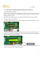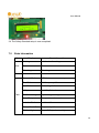
1
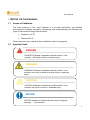
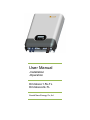
 User Manual
-Installation
-Operation
Omniksol-1.5k-TL
Omniksol-2k-TL
Omnik New Energy Co.,ltd
User Manual 2 User Manual CATALOG
Catalog ........................................................................................................................................................................................................ 3 1. Notes on this manual .................................................................................................................................................................. 5 1.1 Scope of Validation .................................................................................................................................. 5 1.2 Symbols Used ........................................................................................................................................... 5 1.3 Target Group ............................................................................................................................................. 6 2. Preparation ...................................................................................................................................................................................... 7 2.1 Safety Instructions .................................................................................................................................... 7 2.2 Explanations of Symbols on Inverter ..................................................................................................... 9 3. Product Information ................................................................................................................................................................... 11 3.1 Overview .................................................................................................................................................. 11 3.2 Major Characteristics ............................................................................................................................. 12 3.3 Datasheet ................................................................................................................................................. 13 4. Packing checklist ........................................................................................................................................................................ 15 5. 4.1 Assembly parts........................................................................................................................................ 15 4.2 Product Appearance .............................................................................................................................. 16 4.3 Product Identification .............................................................................................................................. 17 4.4 Further Information ................................................................................................................................. 17 Installation ...................................................................................................................................................................................... 18 5.1 Safety ....................................................................................................................................................... 18 5.2 Mounting Instructions ............................................................................................................................. 18 5.3 Safety Clearance .................................................................................................................................... 19 5.4 Mounting Procedure ............................................................................................................................... 20 5.5 Safety lock ............................................................................................................................................... 21 6. Electrical Connection ................................................................................................................................................................ 22 6.1 Safety ....................................................................................................................................................... 22 6.2 Overview of Connection Area ............................................................................................................... 23 6.3 AC Side Connection ............................................................................................................................... 23 6.4 DC Side Connection ............................................................................................................................... 27 6.5 Communication and Monitoring Device .............................................................................................. 32 3 User Manual Display ............................................................................................................................................................................................. 33 7. 7.1 LCD Panel ............................................................................................................................................... 33 7.2 LCD Display ............................................................................................................................................. 34 7.3 Set Language .......................................................................................................................................... 36 7.4 Instructions of Safety Standard selection when power-up ............................................................... 37 7.5 State Information .................................................................................................................................... 38 8. Recycling and Disposal ........................................................................................................................................................... 39 9. Troubleshooting ........................................................................................................................................................................... 40 10. Abbreviation .............................................................................................................................................................................. 41 11. Contact ........................................................................................................................................................................................ 42 4 User Manual 1. NOTES ON THIS MANUAL
1.1
Scope of Validation
The main purpose of this User’s Manual is to provide instructions and detailed
procedures for installing, operating, maintaining, and troubleshooting the following two
types of Omnik New Energy-Solar Inverters:
•
Omniksol-1.5k-TL
•
Omniksol-2k-TL
Please keep this user manual all time available in case of emergency.
1.2
Symbols Used
DANGER
DANGER indicates a hazardous situation which, if not
avoided, will result in death or serious injury.
WARNING
WARNING indicates a hazardous situation which, if not
avoided, can result in death or serious injury or moderate
injury
CAUTION
CAUTION indicates a hazardous condition which, if not
avoided, can result in minor or moderate injury.
NOTICE
NOTICE indicates a situation that can result in property
damage, if not avoided.
5 User Manual 1.3
Target Group
•
Chapter 1, 2, 3, 4, 7, 8, 9, 10 and Chapter 11 are intended for anyone who is
intended to use Omnik Grid Tie Solar Inverter. Before any further action, the operators must
first read all safety regulations and be aware of the potential danger to operate high-voltage
devices. Operators must also have a complete understanding of this device’s features and
functions.
WARNING
Do not use this product unless it has been successfully installed
by qualified personnel in accordance with the instructions in
Chapter 5, “Installation”.
•
Chapter 5 and Chapter 6 are only for qualified personnel who are intended to install
or uninstall the Omnik Grid Tie Solar Inverter.
NOTICE
Hereby qualified personnel means he/she has the valid license
from the local authority in:
• Installing electrical equipment and PV power systems
(up to 1000 V).
• Applying all applicable installation codes.
• Analyzing and reducing the hazards involved in
performing electrical work.
• Selecting and using Personal Protective Equipment
(PPE).
6 User Manual 2. PREPARATION
2.1
Safety Instructions
DANGER
DANGER due to electrical shock and high voltage
DO NOT touch the operating component of the inverter, it
might result in burning or death.
TO prevent risk of electric shock during installation and
maintenance, please make sure that all AC and DC terminals
are plugged out.
DO NOT stay close to the instruments while there is severe
weather conditions including storm, lighting etc.
WARNING
The installation , service , recycling and disposal of the
inverters must be performed by qualified personnel only in
compliance with national and local standards and
regulations. Please contact your dealer to get the
information of authorized repair facility for any maintenance
or repairmen.
Any unauthorized actions including modification of product
functionality of any form will affect the validation of warranty
service; Omnik may deny the obligation of warranty service
accordingly.
NOTICE
Public utility only
The PV inverter designed to feed AC power directly into the
public utility power grid,do not connect AC output of the
device to any private AC equipment.
7 User Manual CAUTION
The PV inverter will become hot during operation; please
don’t touch the heat sink or peripheral surface during or
shortly after operation。
Risk of damage due to improper modifications.
Never modify or manipulate the inverter or other components
of the system.
8 User Manual 2.2
Explanations of Symbols on Inverter
Symbol
Description
Dangerous electrical voltage
This device is directly connected to public grid, thus all
work to the inverter shall only be carried out by
qualified personnel.
DANGER to life due to high electrical voltage!
There might be residual currents in inverter because
of large capacitors. Wait 10 MINUTES before you
remove the front lid.
NOTICE, danger!
This device directly connected with electricity
generators and public grid.
Danger of hot surface
The components inside the inverter will release a log
of heat during operation, DO NOT touch aluminum
housing during operating.
An error has occurred
Please go to Chapter 10 “Trouble Shooting” to remedy the
error.
This device SHALL NOT be disposed of in
residential waste
Please go to Chapter 9 “Recycling and Disposal” for
proper treatments.
Without Transformer
This inverter does not use transformer for the isolation
function.
German mark of conformity
The inverter complies with the requirement of the
German Grid Regulations.
Certified Safety
The inverter complies with the requirements of the
Equipment and Product Safety Act in Europe.
Standards Association of Australian
The inverter complies with the requirement of the
AS4777.
CE Mark
Equipment with the CE mark fulfils the basic
requirements of the Guideline Governing Low-Voltage
and Electromagnetic Compatibility.
9 User Manual No unauthorized perforations or modifications
Any unauthorized perforations or modifications are
strictly forbidden, if any defect or damage
(device/person) is occurred, Omnik shall not take any
responsibility for it.
10 User Manual 3. PRODUCT INFORMATION
3.1
Overview
•
Industrial Layout
、
•
Excellent Heat Elimination
11 •
3.2
User Manual Effective Shield For DC/AC/Communication Connections
Major Characteristics
Omnik inverter has following characteristics which make Omnik inverter “High Efficiency,
High Reliability, High Cost Effective Ratio”
•
•
•
•
Wide DC input voltage and current ranges, enables more PV panels connected.
Wide MPP voltage range ensure high yield under various weather conditions.
High MPP tracking accuracy, ensure the minimum power loses during converting.
Complete set of protection methods.
Also, following protection methods are integrated in Omnik inverter:
•
•
•
•
•
•
•
Internal overvoltage
DC insulation monitoring
Ground fault protection
Grid monitoring
Ground fault current monitoring
DC current monitoring
Integrated DC switch (Optional)
12 User Manual 3.3
Datasheet
Type
Omniksol-1.5k-TL
Omniksol-2k-TL
Input (DC)
Max. PV-generator power
Max DC voltage
MPPT DC voltage range
Turn off DC Voltage
Max. DC current
Nominal DC current
Number of DC connection
DC-connection
Number of MPP trackers
Turn on power
Ppv
Vmax(DC)
Vmppt
Vmin(DC)
Imax(DC)
IN(DC)
[W]
[V]
[V]
[V]
[A]
[A]
1750
2300
500
120 - 450
120
18
14
16.5
1
MC4
1
Pmin(DC) [W]
10
Output (AC)
Max. AC Power
Nominal AC power
Max. AC current
Nominal AC current
Power connection
Pmax(AC)
PN(AC)
Imax(AC)
IN(AC)
[V]
[W]
[A]
[A]
Grid voltage range
Grid frequency range
Power factor
Harmonic distortion (THD) at nominal output
AC Connector
1650
2200
1500
2000
9.0
12.0
6.5
8.5
Single phase
Single phase
According to VDE 0126-1-1, RD1663, ENEL2010,C10/11,
G83/1 AS4777
According to VDE 0126-1-1, RD1663, ENEL2010,C10/11,
G83/1, AS4777
0.99 (>30% of Full Load)
<2%
Plug-in connector
Power consumption
Own consumption in operation
Power consumption at night
Power consumption at standby
Pown(AC) [W]
Pnig(AC) [W]
Pstd(AC) [W]
30
0
6
Efficiency
Max. Efficiency (at 360VDC)
Euro efficiency (at 360VDC)
MPPT efficiency
97.5%
96.6%
99.9%
Safety and protection
Internal overvoltage protection
DC Insulation monitoring
Earth fault protection
Yes
Yes
Yes
According to VDE 0126-1-1, RD1663, ENEL2010,C10/11
G83/1, AS4777
According to VDE 0126-1-1, RD1663, ENEL2010,C10/11
G83/1, AS4777
According to VDE 0126-1-1, RD1663, ENEL2010,C10/11
G83/1, AS4777
According to VDE 0126-1-1, RD1663, G83/1, AS4777
Grid monitoring
Earth fault current monitoring
DC current monitoring
Islanding protection
Normative reference
EN 62109, EN 61000-6-1, EN 61000-6-3, EN 61000-6-2, EN
61000-6-4
EN61000-3-2, EN61000-3-3, EN61000-3-12, EN61000-3-11
CE- compliant according to
Dimensions and weight
Dimensions (WxHxD)
[mm]
330x425x130
13 User Manual Weight
[kg]
13
Environmental limits
IP protection type
Operating temperature range
Relative humidity
Maximum altitude (above sea level)
Noise level
[m]
[dBA]
IP 65 according to IEC 60529
-20°C to +60°C
0% to 98%, no condensation
2000
< 40
General data
Isolation type
Cooling concept
Housing
Mounting information
LED display
LCD display
Data logger
Data communication interfaces
Computer Communication
Standard warranty
Transformerless
Convection
Metal housing for inside and outside installation
Wall bracket
3
Backlight, 16 x 2 Character LCD
RS485, Optional (Wi-Fi, GPRS, Ethernet)
RS232 as Option
5 years (optional 10 years)
14 User Manual 4. PACKING CHECKLIST
4.1
Assembly parts
After you receive the Omnik inverter, please check if there is any damage on the carton,
and then check the inside completeness for any visible external damage on the inverter
or any accessories. Contact your dealer if anything is damaged or missing.
A B C D E F Object Quantity
G
H Description
A
1
Omnik inverter
B
1 pair
DC connector
C
1
AC connector
D
1
Ring tool to disconnect DC connector
E
4
Screw (ST6×50)
F
4
Expansion tube
G
1
Installation and operating instructions
15 User Manual H
4.2
1
DC Switch (Optional)
Product Appearance
•
Front
F B C D E A Object
•
Description
A
Removable front shield
B
LED light(Green) – RUN
C
LED light(Red) – FAULT
D
LED light(Yellow) – COM
E
Function key for displays and choice of language
F
Monitoring LCD with backlighting
Bottom
A
B
C
16 User Manual Object
4.3
Description
A
Plug connectors for DC input.
B
RS232/RS485 interface
C
Terminal for grid connection (AC output)
Product Identification
You can identify the inverter by the side nameplate. Information such as serial number
(SN.), type of the inverter, as well as inverter specifications are specified on the side
name plate. The name plate is on the middle part of the right side of the inverter housing.
And the following figure is the side name plate example as on Omniksol-1.5k-TL.
4.4
Further Information
If you have any further questions concerning the type of accessories or installation,
please check our website www.omnik-solar.com or contact our service hotline.
17 User Manual 5. INSTALLATION 5.1
Safety
DANGER
DANGER to life due to potential fire or electricity shock.
DO NOT install the inverter near any inflammable or
explosive items.
This inverter will be directly connected with HIGH
VOLTAGE power generation device, the installation must
be performed by qualified personnel only in compliance with
national and local standards and regulations.
NOTICE
NOTICE due to the inappropriate or the harmonized
installation environment may jeopardize the life span
of the inverter.
Installation directly expose under intensive sunshine is not
recommended.
The installation site MUST have good ventilation condition.
5.2
Mounting Instructions
Max 15° 18 •
•
•
•
•
•
•
•
•
5.3
User Manual Omnik inverter is designed for indoors and outdoors installation
Please mount the inverter in the direction as illustrated above
Install the inverter in the vertical direction is recommended, with a max.15 degrees
backwards.
For the convenience of checking the LCD display and possible maintenance
activities, please install the inverter at eye level.
Make sure the wall you selected is strong enough to handle the screws and bear the
weight of the inverter
Ensure the device is properly fixed to the wall
It is not recommended that the inverter is exposed to the strong sunshine, because
the excess heating might lead to power reduction
The ambient temperature of installation site should be between -20 °C and +60 °C
( between -4 °F and 140 °F )
Make sure the ventilation of the installation spot, not sufficient ventilation may reduce
the performance of the electronic components inside the inverter and shorten the life
of the inverter
Safety Clearance
Observe the following minimum clearances to walls, other devices or objects to
guarantee sufficient heat dissipation and enough space for pulling the electronic solar
switch handle.
30 CM
10 CM
30 CM
10 CM
19 User Manual Direction
5.4
Minimum clearance
Above
30 cm
Below
30 cm
Sides
10 cm
Mounting Procedure
1. Mark 4 positions of the drill holes on the wall according to the paper installation
position scale packed in the carton box.
4-Φ12
2 5 4 ±1
32±±
0 2
2. First, according to the marks, drill 4 holes in the wall. Then, place four expansion
tubes in the holes using a rubber hammer. Next, wring 4 screws into the expansion
tubes.
20 User Manual 3. First check the 4 holes in the backside of the inverter. Then, lift the inverter carefully,
align the 4 holes in the inverter and the 4 screws in the wall, and finally attach the
inverter to the screws slightly.
4. Please carefully check the accessories and original carton to make sure every
necessary part is used and nothing is missing during installation.
5.5
Safety lock
Recommended padlock dimension:
A φ
B
C
A.Shackle Diameter
5~7 mm
B.Vertical Clearance
8~15 mm
C.Horizontal Clearance
12~20 mm
Stainless, solid hanger and secured lock cylinder
21 User Manual NOTICE
For further maintenance and possible repair, please keep the
key of the padlock in a safe place.
After the inverter is hang up on the wall, install the lock bracket on the aluminium radiator at the
Lower Right Corner of the inverter (as the picture showed below),make sure the round hole of
the lock bracket aim at the hole of the inverter, after that lock up the device.
The lock bracket 6. ELECTRICAL CONNECTION
6.1
Safety
DANGER
DANGER to life due to potential fire or electricity shock. With
the inverter powered, comply with all prevailing national
regulations on accidents prevention.
This inverter
will be directly connected with HIGH VOLTAGE power
generation device, the installation must be performed by
qualified personnel only in compliance with national and local
standards and regulations.
22 User Manual NOTICE
Electrical connections shall be carried out in
accordance with the applicable regulations, such as
conductor sections, fuses, PE connection.
6.2
Overview of Connection Area
A B
Object
6.3
C
Description
A
Plug connectors for DC input.
B
RS232/RS485 interface
C
Terminal for grid connection (AC output)
AC Side Connection
23 User Manual DANGER
DANGER to life due to potential fire or electricity shock.
NEVER connect or disconnect the connectors under load.
1. Integrated RCD and RCM
The Omniksol inverter is equipped with integrated RCD (Residual Current Protective
Device) and RCM (Residual Current Operated Monitor). The current sensor will detect
the volume of the leakage current and compare it with the pre-set value, if the leakage
current exceeds the permitted range, the RCD will disconnect the inverter from the AC
load.
2. Cable assembly install Instruction
Connector explore figure:
Cable gland
Cable gland body
Adapter
Connector body
2.1 install the cable glad cap, cable gland body and adapter to the cable.
24 User Manual 2.2 strip outer jacket 60mm max. Trim flush the filler with the jacket ,then strip each
insulation 12+/-1mm
2.3 insert conductor strands into socket, and lock the screw with driver at torque 3.5+/0.5kgf.com. the ground wire must be locked into”PE” hole. (From front end, to find the
PE hole)
2.4 install the adapter, cable gland body and cable cap to connector body per below
picture 1-3.
25 User Manual Picture 1
Picture 2
Picture 3
3. Mating step for special PPC AC connector:
3.1 move the plug closer the receptacle, the key aim at the keyway.
3.2 clock wise rotations the coupling nut and hear the click-close
26 User Manual 3.3 counterclockwise rotations the coupling nut-Open
6.4
DC Side Connection
DANGER
DANGER to life due to potential fire or electricity shock.
NEVER connect or disconnect the connectors under load.
NOTICE
DC Switch (Optional) may be integrated or external to
Inverter, and it can be used to connect or disconnect the
DC source from Inverter.
For Omniksol-1.5k-TL and Omniksol-2k-TL, there is only one MPP Tracker, and the DC
characteristics of them are illustrated as the following table.
27 User Manual Inverter Type
Omniksol-1.5k-TL
Omniksol-2k-TL
MPP
Tracker
1
Max. DC
Power
Max. DC
Voltage
1750W
2300W
Max. DC
Current
18A
500V
18A
MC4 Assembly instructions
If, during self assembly, parts and tools other than those stated by MC are used or
if the preparation and assembly instructions described here are disregarded then neither
safety nor compliance with the technical data can be guaranteed.
For protection against electric shock, PV-connectors must be isolated from the
power supply while being assembled or disassembled.
The end product must provide protection from electric shock.
The use of PVC cables is not recommended.
Unplugging under load: PV plug connections must not be unplugged while under
load. They can be placed in a no load state by switching off the DC/AC converter or
breaking the DC circuit interrupter. Plugging and unplugging while under voltage is
permitted.
It is unadvisable to use non-tinned cables of type H07RN-F, since with oxidised
copper wires the contact resistances of the crimp connection may exceed the permitted
limits.
Disconnected connectors should be protected from dirt and water with sealing
caps.
Plugged parts are watertight IP67. They can not be used permanently under
water. Do not lay the MC-PV connectors on the roof surface.
See the MC catalogue 2 Solar line for technical data and assembled parts.
PV-Female cable coupler
PV-KBT4/…
Touch protection,
mated/unmated
IP67/IP2X
PV-Male cable coupler
PV-KST4/…
Rated current
Optional
PV-SSH4
17A(1,5mm2/14AWG)
28 User Manual 22A(2,5mm2/ 12AWG)
30A(4mm2,6mm2/ 10AWG)
Ambient
temperature
range
-40° ...90°C (IEC/CEI) 40° ...75°C(UL) 40° ...70°C (UL/AWG14)
Rated voltage
1000V (IEC/CEI) 600V (UL)
Upper limiting
temperature
105°C (IEC/CEI)
Safety class
II
Tools required
(ill.1) Crimping tool incl. locator and
built-in crimping insert.
Type: PV-ES-CZM-18100
PV-ES-CZM-19100
(ill.2) Interchangeable crimping
inserts incl. hexagonal screwdriver A/F
2,5.
Type: PV-ES-CZM-18100
PV-ES-CZM-19100
(ill.3) Open-end spanner PV-MS 1 set =
2 pieces Order No. 32.6024
(ill.4) PV-WZ-AD/GWD socket wrench
insert to tighten, Order No. 32.6006
(ill.5) PV-SSE-AD4 socket wrench insert
to secure PV-SSE-AD4, Order No.
32.6026
29 User Manual (ill.6) Open-end spanner A/F 15 mm
(ill.7) Torque screwdriver A/F 12 mm
(ill.8) Test plug PV-PST
Order No.: 32.6028
Cable preparation
(ill.9) Important: Cables with class 2, 5
or 6 construction can be connected. It is
advantageous to use tinned conductors.
It is unadvisable to use non-tinned cables
of type H07RN-F, since with oxidised
copper wires the contact resistances of
the crimp connection may exceed the
permitted limits.
Check dimension b according to the
following table:
(ill.10) Strip cable insulation. L = 6-7, 5
mm. Take care not to cut individual
strands.
Recommended tool:
Stripping pliers PV-AZM,Order
No.32.6027
30 User Manual Crimping
(ill.11) Notes to the operation ofthe
crimping pliers, see¬MA251-def
(www.multicontact.com)
(ill.12) Push the crimped contact into the
socket resp. plug insulator until it
engages. Pull lightly on the lead to check
that the metal part has engaged.
Assembly control
(ill.13) Insert the test pin with the
corresponding side into the socket or plug
to the end position. If the contact is
correctly assembled, the white marking
on the test pin
must be still visible.
(ill.14) Screw on the cable gland, handtight, with the tools PV-MS. Or
Screw on the cable gland, with the tools
PV-WZ-AD/GWD and PV-SSE-AD4
In any case:
The tightening torque must be adapted to
the solar cables used in each specific
case. Typical values lie in a range
between 2,5 Nm to 3 Nm.
Plugging and unplugging the cable
coupler without safety lock clip PV-SSH4
Plugging
(ill.15)
Plug the coupling together until they
engage. Check correct engagement by
pulling on the coupling.
31 User Manual Unplugging
(ill.16)
Compress the two snap-in springs (X) by
hand or with the PV-MS tool and
separate the coupling.
Plugging and unplugging the cable
coupler without safety lock clip PV-SSH4
Refer to cable manufactures specification for minimum bending radius.
6.5
Communication and Monitoring Device
There are 2 plugs in the bottom side of the Omnik inverter as the following figure:
These 2 plugs are used for multipoint communications, that is, up to 50 Omnik inverters
can be connected one by one through these 2 plugs and the cables, the upper
computer can communicate with these inverters via a single signal cable at the same
time, and maximum length of the cable is 1000m. Through these plugs, the user can get
the data from these inverters, and can also configure parameters of them.
32 User Manual 7. DISPLAY 7.1
LCD Panel
E A B C
D
Object
Description
A
LED light(Green) – RUN
B
LED light(Red) – FAULT
C
LED light(Yellow) – COM
D
Function key for displays and choice of language
E
Monitoring LCD with backlighting
The LCD panel is integrated in the front lid of the inverter, so it is easy for user to check
and set the data. In addition, the user can press the function key to illuminate the LCD
screen.
NOTICE
Omnik inverter is not an aligned measuring instrument
for current, voltage or power consumption. A slight
deviation of a few percent points is intrinsic to the
system, the results from the inverter cannot be used for
grid balance calculations. An aligned meter will be
required to make calculations for the utility company.
33 User Manual 7.2
LCD Display
NOTICE
Make sure the DC switch(Optional) is switched to “On”
position, otherwise the inverter cannot work due to power
shortage.
The display content consists of 2 lines. The bottom line (Line 2) always displays the
output power (Pac = xxxx W). The top line (Line 1) shows current state information by
default, and by pressing function key it will display different operating information as the
following flow chart and table.
34 User Manual State information
Pac = xxxx W
E-today
Pac = xxxx W
E-total
Pac = xxxx W
Vpv
Pac = xxxx W
Ipv
Pac = xxxx W
Iac
Pac = xxxx W
Frequency
Pac = xxxx W
Model
Pac = xxxx W
Ver
Pac = xxxx W
Set Language
Pac = xxxx W
Vac
Pac = xxxx W
35 User Manual Line 1
Description
State
information
Current state information: all possible content shows in the following
table, reference to 7.4 for further information
E-today
The energy generated today in kilo watt hours (kWh)
E-total
The energy generated since starting up the inverter (kWh)
Vpv
The present voltage of the solar generator
Ipv
The present current of the solar generator
Iac
The present grid current
Frequency
The grid frequency
Model
The type of the inverter
Ver
The Firmware version
Set Language
Several languages are provided for users, reference to 7.3 for further
information
Vac
The grid voltage
7.3
Set Language
The Omnik inverter provides several languages for users to use. At the entry of “Set
Language”, press the key for approx. 5 seconds, you can enter the language selection
menu. Choose the language which you need with the function key, and keep this state
without any operation. When it returns to the main menu automatically, the setting has
been saved.
36 7.4
User Manual Instructions of Safety Standard selection when power-up
1. Attentions before the operation:
Only perform this operation when the voltage value displayed on Omnik inverter’s LCD falls
between 150V and 450V for 1.5kW/2.0kW inverters or between 150V and 550V for
3.0kW/4.0kW/5.0kW inverters.
Only perform this operation when the accumulative generated electricity is less than 1KWh.
2. Operation steps are as following:
2.1 Power on the inverter with only DC side connected, while disconnecting cables of AC side.
2.2 Press the Function button until the LCD displays inverter’s model and hold the button for 5
seconds or more when the LCD displays the current Safety Standard. Change the standard by
pressing the Function button one at a time.
Function button
2.3 When the LCD displays your desired Safety Standard, hold the Function button for 5
seconds or more until it shows ”Safety Standard OK”.
37 User Manual 2.4 The Safety Standard setup is now completed.
7.5
State Information
State
Wait
Display
Waiting
Initialization & waiting
Reconnect s
Reconnect
Checking s
Checking
Normal Normal
Fault
State information
Normal state
Ground I Fault
GFCI failure oversized leakage current
Fac Failure
Grid frequency failure
Vac Failure
Grid voltage failure
Utility Loss
No Utility&Island
PV Over Voltage
Input voltage too high
Over Temperature
Temperature abnormal
Isolation Fault
Isolation failure
Relay-Check Fail
Output relay failure
DC INJ High
Output DC injection too high
38 User Manual EEPROM R/W Fail EEPROM problem
Flash
SCI Failure
Serial communication interface failure
AC HCT Failure
Output AC sensor abnormal
GFCI Failure
GFCI testing device abnormal
F/W Updating
Update
About the further information for each fault, please reference to Chapter
“9.TROUBLESHOOTING”.
8. RECYCLING AND DISPOSAL
To comply with European Directive 2002/96/EC on waste Electrical and Electronic
Equipment and its implementation as national law, electrical equipment that has
reached the end of its life must be collected separately and returned to an approved
recycling facility. Any device that you no longer required must be returned to your dealer
or you must find an approved collection and recycling facility in your area.
Ignoring this EU Directive may have severe affects on the environment and your health.
WARNING
This device SHALL NOT be disposed of in
residential waste.
39 User Manual 9.
TROUBLESHOOTING LCD display
Isolation Fault
Ground I Fault
Grid Fault
Fac Over Range
Resumable Vac Over Range
Fault
Utility Loss
Over Temperature
PV over Voltage
Consistent Fault
Possible actions
1. Check the impedance between PV (+) & PV (-) and the
inverter is earthed. The impedance must be greater
than 2MΩ.
2. Check whether the AC-side has contacts with earth.
1. The ground current is too high.
2. After cut off the AC side connection, unplug the inputs
from the PV generator and check the peripheral AC
system.
3. After the cause is cleared, re-plug the PV panel and
AC connection, and check PV-Inverter status.
1. Wait for a moment, if the grid returns to normal, PVInverter automatically restarts.
2. Make sure grid voltage and frequency meet the
specifications.
1.
2.
3.
4.
Grid is not connected.
Check grid connection cables.
Check grid usability.
If grid is ok, and the problem persists, maybe the fuse
in the inverter is open, please call service.
1. The internal temperature is higher than specified
normal value.
2. Find a way to reduce the ambient temperature.
3. Or move the inverter to a cooler environment.
1. Check the open PV voltage, see if it is greater than or
too close to 500VDC (for Omniksol-1.5k-TL
or
Omniksol-2k-TL).
2. If PV voltage is less than 500VDC, and the problem
still occurs, please call local service.
Disconnect PV (+) or PV (-) from the input, restart the
inverter.
Relay-Check Fail
Permanent
Fault
DC INJ High
EEPROM R/W Fail
SCI Failure
1.
2.
3.
4.
Disconnect ALL PV (+) or PV (-).
Wait for a few seconds.
After the LCD switches off, reconnect and check again.
If the problems remain please call local service.
AC HCT Fault
GFCI Failure
40 User Manual 10. ABBREVIATION
LCD
Liquid Crystal Display
LED
Light Emitting Diode
MPPT
Maximum Power Point Tracking
PV
Photovoltaic
Vdc
Voltage at the DC side
Vac
Voltage at the AC side
Vmpp
Voltage at the Maximum Power Point
Impp
Amperage at Maximum Power Point
AC
Alternating Current ( Form of electricity supplied by Utility
Company )
DC
Direct Current ( Form of electricity generated by PV modules )
VDE 0126-1-1
German standards for establishing suitability for Grid
Connection of the Inverter.
DC Switch
Switch in the DC Circuit. Disconnects DC source from Inverter.
May be integrated or external to Inverter.
41 User Manual 11. CONTACT
Suzhou Headquarter
Xinghu Road No.218 bioBAY Park C2-101 215123 Suzhou China
Tel: +86 512 6295 6676
Fax: +86 512 6295 6682
Email: [email protected]
www.omnik-solar.com
Omnik German Service Center
An der Pikardie 6
01277 Dresden
Deutschland
Tel: +49 (0)351 30986031
Fax: +49 (0)351 30930022
Email: [email protected]
Service line
Tel: +86 512 6295 6676
Fax: +86 512 6295 6682
Email: [email protected]
42