1
User’s
Manual
Model ISC202G [Style: S2], ISC202S [Style: S3]
2-wire Inductive Conductivity
Transmitter
IM 12D06A03-01E
IM 12D06A03-01E
7th Edition
TABLE OF CONTENTS
PREFACE
1. Introduction And General Description ............................................................. 1-1
1-1. Instrument check ............................................................................................ 1-1
1-2. Application ...................................................................................................... 1-3
2. GENERAL SPECIFICATIONS ............................................................................. 2-1
2-1. Specifications.................................................................................................. 2-1
2-2. Model and suffix codes ................................................................................... 2-6
2-3. Control Drawing ISC202S mA HART® Specification (IECEx). ....................... 2-7
2-4. Control Drawing ISC202S mA HART® Specification (ATEX) ......................... 2-8
2-5. Control Drawing ISC202S mA HART® Specification
(FM Intrinsically safe design) ........................................................................... 2-9
2-6. Control Drawing ISC202S mA HART® Specification
(FM Non-incendive design) ............................................................................ 2-10
2-7. Control Drawing of ISC202S mA HART® Specification (CSA) ......................2-11
2-8. Control Drawing of ISC202S FF/PB Specification (IECEx) .......................... 2-12
2-9. Control Drawing of ISC202S FF/PB Specification (ATEX) ........................... 2-13
2-10. Control Drawing of ISC202S FF/PB Specification
(FM Intrinsically safe Entity) ........................................................................... 2-14
2-11. Control Drawing of ISC202S FF/PB Specification
(FM Intrinsically safe FISCO) ......................................................................... 2-16
2-12. Control Drawing of ISC202S FF/PB Specification
(FM Non-incendive Entity) ............................................................................. 2-18
2-13. Control Drawing of ISC202S FF/PB Specification
(FM Non-incendive FNICO) ........................................................................... 2-19
2-14. Control Drawing of ISC202S FF/PB Specification (CSA) ........................... 2-20
3. Installation And Wiring....................................................................................... 3-1
3-1. Installation and dimensions ............................................................................ 3-1
3-1-1. Installation site .................................................................................................................3-1
3-1-2. Mounting methods ...........................................................................................................3-1
3-2. Preparation ..................................................................................................... 3-2
3-2-1. Cables, terminals and glands ..........................................................................................3-2
3-3. Wiring of sensors ............................................................................................ 3-3
3-3-1. General precautions ........................................................................................................3-3
3-3-2. Additional precautions for installations in hazardous areas ...........................................3-3
3-3-3. Installation in: Hazardous Area-Non-Incendive ..............................................................3-3
3-4 Wiring of the power supply .............................................................................. 3-4
3-4-1 General precautions .........................................................................................................3-4
3-4-2. Connection of the power supply ......................................................................................3-4
3-4-3. Switching the instrument on ............................................................................................3-4
3-5. Sensor wiring .................................................................................................. 3-4
3-6. Other sensor systems ..................................................................................... 3-5
3-6-1. Sensor cable connections using junction box (BA10) and extension cable (WF10).......3-5
4. Operation; Display Functions And Setting ...................................................... 4-1
4-1. Operator interface ........................................................................................... 4-1
4-2. Explanation of operating keys......................................................................... 4-2
4-3. Setting passcodes .......................................................................................... 4-3
4-3-1. Passcode protection ........................................................................................................4-3
4-4. Display examples............................................................................................ 4-3
4-5. Display functions............................................................................................. 4-4
IM 12D06A03-01E
7th Edition: Oct. 2009(YK)
All Rights Reserved, Copyright © 2001, Yokogawa Electric Corporation
IM 12D06A03-01E
5. Parameter setting ............................................................................................... 5-1
5-1. Maintenance mode ......................................................................................... 5-1
5-1-1.
5-1-2.
5-1-3.
5-1-4.
5-1-5.
Introduction ......................................................................................................................5-1
Manual calibration to determine the cell constant (C.C.) ................................................5-2
Second Line display. Referring to the first compensated conductivity. ...........................5-3
Second Line display. Referring to the second compensated conductivity. .....................5-4
Manual activation of HOLD ............................................................................................5-5
5-2-1.
5-2-2.
5-2-3.
5-2-4.
5-2-5.
Linear output (Range)......................................................................................................5-7
HOLD ..............................................................................................................................5-8
Temperature compensation .............................................................................................5-9
Temperature compensation for first conductivity value .................................................5-11
Temperature Compensation for second conductivity value ..........................................5-12
5-3-1.
5-3-2.
5-3-3.
5-3-4.
5-3-5.
5-3-6.
5-3-7.
Parameter specific functions .........................................................................................5-13
Temperature measuring functions .................................................................................5-13
Temperature compensation functions ...........................................................................5-14
mA output functions .......................................................................................................5-16
User interface ................................................................................................................5-18
Communication setup ....................................................................................................5-19
General .........................................................................................................................5-19
5-2. Commissioning mode ..................................................................................... 5-6
5-3.Service Codes ............................................................................................... 5-13
6. Calibration ....................................................................................................... 6-1
6-1 When is calibration necessary? ....................................................................... 6-1
6-2. Calibration procedure ..................................................................................... 6-2
7. Maintenance ....................................................................................................... 7-1
7-1. Periodic maintenance for the EXA 202 transmitter ......................................... 7-1
7-2. Periodic maintenance of the sensor ............................................................... 7-1
8. Troubleshooting ................................................................................................. 8-1
8-1. Introduction ..................................................................................................... 8-1
8-2. Self diagnostics of the conductivity sensor ..................................................... 8-1
8-3. Self diagnostics of the temperature sensor .................................................... 8-1
8-4. Self diagnostics of the electronics .................................................................. 8-1
8-5. Checking during operation .............................................................................. 8-1
9. Error messages and explanation ...................................................................... 9-1
10. Spare Parts ..................................................................................................... 10-1
11. Appendix 1 ....................................................................................................... 1-1
11-1. User setting for non-linear output table (code 31, 35)................................... 1-1
11-2. User entered matrix data (code 23 to 28) ..................................................... 1-1
11-3. Matrix data table (user selectable in code 22) .............................................. 1-2
11-4. Configuration Checklist For ISC202 ............................................................. 1-3
11-5. Coded service settings (default) ................................................................... 1-3
11-6. Device Description (DD) menu structure ...................................................... 1-4
IM 12D06A03-01E
12. APPENDIX 2....................................................................................................... 2-1
12-1. Preface ........................................................................................................ 2-1
12-2. Wiring diagrams............................................................................................. 2-1
12-3. Peripheral products........................................................................................ 2-2
12-3-1. PH201G*B Dedicated Distributor..................................................................................2-2
12-3-2. BA20 Junction Terminal Box.........................................................................................2-3
12-3-3. WF10J Extension Cable................................................................................................2-4
12-4. Quick reference for parameter setting.......................................................... 2-5
12-4-1. Settings Performed in Maintenance Mode................................................. 2-6
12-4-1-1 Calibration with solution of known conductivity ...................................... 2-6
12-4-1-2 Selecting Items for Display .......................................................................................2-6
12-4-2. Commissioning Mode Settings ................................................................ 2-7
12-4-2-1
12-4-2-2
12-4-2-3
12-4-2-4
Output Range Setting ...............................................................................................2-7
Setting Hold Functions ...............................................................................................2-7
Temperature Compensation .....................................................................................2-8
Correcting Zero Offset Error by Calibration in Air (Air Set) .......................................2-8
12-4-3. Actual Setting Examples . ....................................................................... 2-9
12-4-3-1 Setting Output in terms of Concentration ..............................................................2-10
12-4-3-2 Key Operation Procedure Examples ......................................................................2-15
12-5. Installation factor adjustment...................................................................... 2-19
13. Appendix 3 QUALITY INSPECTION.................................................................. 3-1
13-1. ISC202G 2-Wire Inductive Conductivity Transmitter..................................... 3-1
13-2. ISC202S 2-Wire Inductive Conductivity Transmitter...................................... 3-6
13-3. ISC202G, ISC202S 2-Wire Inductive Conductivity Transmitter
(Fieldbus Communication)...............................................................................3-11
13-4. ISC202G, ISC202S 2-Wire Inductive Conductivity Transmitter
(Profibus Communication).............................................................................. 3-15
Customer Maintenance Parts List for ISC202G (Style : S2)........CMPL12D06A03-02E
Customer Maintenance Parts List for ISC202S (Style : S3)....CMPL12D06A03-23E
Revision Record...........................................................................................................i
In this manual a mA sign appears if it concerns the ISC202G-A and ISC202S-A, -N, -K.
IM 12D06A03-01E
PREFACE
DANGER
Notice
• This manual should be passed on to the end
user.
Electric discharge
• The contents of this manual are subject to
The EXA analyzer contains devices that can be
change without prior notice.
damaged by electrostatic discharge. When servicing • The contents of this manual shall not be
this equipment, please observe proper procedures
reproduced or copied, in part or in whole,
to prevent such damage. Replacement components
without permission.
should be shipped in conductive packaging. Repair
• This manual explains the functions contained in
work should be done at grounded workstations using
this product, but does not warrant that they are
grounded soldering irons and wrist straps to avoid
suitable the particular purpose of the user.
electrostatic discharge.
• Every effort has been made to ensure accuracy
in the preparation of this manual.
Installation and wiring
However, when you realize mistaken
The EXA analyzer should only be used with equipexpressions or omissions, please contact the
ment that meets the relevant international and
nearest Yokogawa Electric representative or
regional standards. Yokogawa accepts no responsisales office.
bility for the misuse of this unit.
• This manual does not cover the special
specifications. This manual may be left
unchanged on any change of specification,
CAUTION
construction or parts when the change does
The instrument is packed carefully with shock
not affect the functions or performance of the
absorbing materials, nevertheless, the instrument
product.
may be damaged or broken if subjected to strong
shock, such as if the instrument is dropped. Handle • If the product is not used in a manner specified
with care.
in this manual, the safety of this product may be
impaired.
Although the instrument has a weatherproof
construction, the transmitter can be harmed if it
Yokogawa is not responsible for damage to the
becomes submerged in water or becomes excesinstrument, poor performance of the instrument
sively wet.
or losses resulting from such, if the problems are
caused by:
Do not use an abrasive material or solvent when
• Improper operation by the user.
cleaning the instrument.
• Use of the instrument in improper applications
• Use of the instrument in an improper
Do not modify the ISC202 transmitter.
environment or improper utility program
• Repair or modification of the related instrument
by an engineer not authorized by Yokogawa.
WARNING
Electrostatic charge may cause an explosion hazard. Safety and Modification Precautions
Avoid any actions that cause the generation of elec- • Follow the safety precautions in this manual
trostatic charge, e.g., rubbing with a dry cloth.
when using the product to ensure protection and
Warning label
safety of the human body, the product and the
system containing the product.
Because the enclosure of the Dissolved Oxygen
transmitter Type ISC202S-A, -P, -F are made of aluminium, if it is mounted in an area where the use of
category 1 G Zone 0 apparatus is required, it must
be installed such, that, even in the event of rare
incidents, ignition sources due to impact and friction
sparks are excluded.
IM 12D06A03-01E
The following safety symbols are used on the
product as well as in this manual.
DANGER DANGER
This symbol indicates that an operator must
follow the instructions laid out in this manual in
order to avoid the risks, for the human body, of
injury, electric shock, or fatalities. The manual
describes what special care the operator must
take to avoid such risks.
WARNING
This symbol indicates that the operator must
refer to the instructions in this manual in
order to prevent the instrument (hardware) or
software from being damaged, or a system
failure from occurring.
CAUTION
This symbol gives information essential for
understanding the operations and functions.
This symbol indicates Protective Ground
Terminal
This symbol indicates Function Ground
Terminal (Do not use this terminal as the
protective ground terminal.)
This symbol indicates Alternating current.
This symbol indicates Direct current.
IM 12D06A03-01E
Warranty and service
Yokogawa products and parts are guaranteed
free from defects in workmanship and material
under normal use and service for a period of
(typically) 12 months from the date of shipment
from the manufacturer. Individual sales organizations can deviate from the typical warranty
period, and the conditions of sale relating to the
original purchase order should be consulted.
Damage caused by wear and tear, inadequate
maintenance, corrosion, or by the effects of
chemical processes are excluded from this warranty coverage.
In the event of warranty claim, the defective
goods should be sent (freight paid) to the service
department of the relevant sales organization for
repair or replacement (at Yokogawa discretion).
The following information must be included in the
letter accompanying the returned goods:
• Part number, model code and serial number
• Original purchase order and date
• Length of time in service and a description of
the process
• Description of the fault, and the circumstances
of failure
• Process/environmental conditions that may be
related to the installation failure of the device
• A statement whether warranty or non-warranty
service is requested
• Complete shipping and billing instructions for
return of material, plus the name and phone
number of a contact person who can be
reached for further information.
Returned goods that have been in contact with
process fluids must be decontaminated/disinfected before shipment. Goods should carry a
certificate to this effect, for the health and safety
of our employees. Material safety data sheets
should also be included for all components of
the processes to which the equipment has been
exposed.
ATEX Documentation
This procedure is only applicable to the countries
in European Union.
GB
All instruction manuals for ATEX Ex related products are available in English, German and French.
Should you require Ex related instructions in your
local language, you are to contact your nearest
Yokogawa office or representative.
DK
Alle brugervejledninger for produkter relateret
til ATEX Ex er tilgængelige på engelsk, tysk og
fransk. Skulle De ønske yderligere oplysninger
om håndtering af Ex produkter på eget sprog, kan
De rette henvendelse herom til den nærmeste
Yokogawa afdeling eller forhandler.
I
Tutti i manuali operativi di prodotti ATEX contrassegnati con Ex sono disponibili in inglese,
tedesco e francese. Se si desidera ricevere i manuali operativi di prodotti Ex in lingua locale, mettersi in contatto con l’ufficio Yokogawa più vicino o
con un rappresentante.
E
Todos los manuales de instrucciones para los productos antiexplosivos de ATEX están disponibles
en inglés, alemán y francés. Si desea solicitar las
instrucciones de estos artículos antiexplosivos en
su idioma local, deberá ponerse en contacto con
la oficina o el representante de Yokogawa más
cercano.
NL
Alle handleidingen voor producten die te maken
hebben met ATEX explosiebeveiliging (Ex)
zijn verkrijgbaar in het Engels, Duits en Frans.
Neem, indien u aanwijzingen op het gebied van
explosiebeveiliging nodig hebt in uw eigen taal,
contact op met de dichtstbijzijnde vestiging van
Yokogawa of met een vertegenwoordiger.
SF
Kaikkien ATEX Ex -tyyppisten tuotteiden käyttöhjeet ovat saatavilla englannin-, saksan- ja
ranskankielisinä. Mikäli tarvitsette Ex -tyyppisten
tuotteiden ohjeita omalla paikallisella kielellännne,
ottakaa yhteyttä lähimpään Yokogawa-toimistoon
tai -edustajaan.
P
Todos os manuais de instruções referentes aos
produtos Ex da ATEX estão disponíveis em Inglês,
Alemão e Francês. Se necessitar de instruções na
sua língua relacionadas com produtos Ex, deverá
entrar em contacto com a delegação mais próxima
ou com um representante da Yokogawa.
F
Tous les manuels d’instruction des produits
ATEX Ex sont disponibles en langue anglaise,
allemande et française. Si vous nécessitez des
instructions relatives aux produits Ex dans votre
langue, veuillez bien contacter votre représentant
Yokogawa le plus proche.
D
Alle Betriebsanleitungen für ATEX Ex bezogene
Produkte stehen in den Sprachen Englisch,
Deutsch und Französisch zur Verfügung. Sollten
Sie die Betriebsanleitungen für Ex-Produkte in
Ihrer Landessprache benötigen, setzen Sie sich
bitte mit Ihrem örtlichen Yokogawa-Vertreter in
Verbindung.
S
Alla instruktionsböcker för ATEX Ex (explosionssäkra) produkter är tillgängliga på engelska, tyska
och franska. Om Ni behöver instruktioner för
dessa explosionssäkra produkter på annat språk,
skall Ni kontakta närmaste Yokogawakontor eller
representant.
GR
IM 12D06A03-01E
SK
PL
CZ
SLO
LT
H
BG
LV
EST
RO
M
IM 12D06A03-01E
Introduction 1-1
1. INTRODUCTION AND GENERAL DESCRIPTION
The Yokogawa EXA 202 is a 2-wire transmitter designed for industrial process monitoring, measurement
and control applications. This user’s manual contains the information needed to install, set up, operate
and maintain the unit correctly. This manual also includes a basic troubleshooting guide to answer typical user questions.
Yokogawa can not be responsible for the performance of the EXA transmitter if these instructions are not
followed.
1-1. Instrument check
Upon delivery, unpack the instrument carefully and inspect it to ensure that it was not damaged during
shipment. If damage is found, retain the original packing materials (including the outer box) and then
immediately notify the carrier and the relevant Yokogawa sales office.
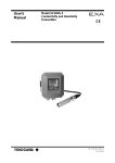
Make sure the model number on the textplate affixed to the side of the instrument agrees with your
order. Examples of nameplates are shown below.
mA
ISC TRANSMITTER
MODEL
SUFFIX
No. IECEx KEM 06.0054X
Zone 0 Ex ia IIC T4
Zone 0 Ex ia IIC T6 for Ta:40°C
IP65
SEE CONTROL DRAWING
No. KEMA 06ATEX0222 X
Ex ia IIC T4
Ex ia IIC T6 for Ta:40°C
SEE CONTROL DRAWING IP65
ISC202
II 1G
24V DC
4 20mA DC
AMB.TEMP. -10 55°C
STYLE
No.
CL I, DIV 1, GP ABCD
R Ex ia IIC T4
LR81741 C
N200
DISSOLVED OXYGEN TRANSMITTER
AMB.TEMP.
Ex ia IIC T6 for Ta:40°C
SEE CONTROL DRAWING
IP65 Type 3S
WARNING
Substitution of
components may impair
intrinsic safety
Made in Japan Tokyo 180-8750 JAPAN
SUPPLY
OUTPUT
NI CL I, DIV 2, GP ABCD AND
CL I, ZN 2, GP IIC
T4
Type 4X
Install per CONTROL DRAWING
IKE028-A10 P.7 to P.8
IS CL I, DIV 1, GP ABCD
AND AEx ia IIC
T4
Type 4X
Install per CONTROL DRAWING
IKE028-A10 P.5 to P.6
SUPPLY
OUTPUT
MODEL
SUFFIX
II 3 G
ISC202G-F
SUPPLY
OUTPUT
AMB.TEMP.
STYLE
No.
0344
DISSOLVED OXYGEN TRANSMITTER
MODEL
SUFFIX
9 TO 32VDC
FF-TYPE113
-10 55°C
AVERTISSEMENT
La substitution de composants
peut compromeltre la securite
intrinseque.
ISC202S-A
ISC202G-P
9 TO 32VDC
PROFIBUS-PA
-10 55°C
ISC202S-N
ISC TRANSMITTER
MODEL
SUFFIX
ISC202S-K
SUPPLY
OUTPUT
24V DC
4 20mA DC
-10 55°C
STYLE
No.
Cert No. GYJ081158X
Ex ia IIC T4
Ex ia IIC T6 for Ta:40˚C
SEE USER’S MANUAL BEFORE USE
Made in Japan Tokyo 180-8750 JAPAN
N200
Ex nA[nL] IIC
NI CL I, DIV 2, GP ABCD
T4
R
T6 for Ta:40°C
IP65 Type 3S
LR81741 C
SEE CONTROL DRAWING
AVERTISSEMENT
WARNING
La substitution de composants
Substitution of
peut rendre ce materiel
components may
inacceptable pour les
impair suitability
emplacements de
for class I, Division 2.
Classe I, Division 2.
AMB.TEMP.
STYLE
No.
Made in Japan Tokyo 180-8750 JAPAN
No. IECEx KEM 06.0054X
Ex nA[nL] IIC T4
Ex nA[nL] IIC T6 for Ta:40°C
IP65
SEE CONTROL DRAWING
No. KEMA 06ATEX0223
EEx nA[nL] IIC T4
EEx nA[nL] IIC T6 for Ta:40°C
IP65
SEE CONTROL DRAWING
Made in Japan Tokyo 180-8750 JAPAN
N200
Figure 1-1. Nameplate
IM 12D06A03-01E
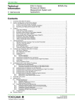
1-2 Introduction
ISC TRANSMITTER
ISC TRANSMITTER
MODEL
SUFFIX
MODEL
SUFFIX
ISC202S-F
17.5VDC
or 24VDC
17.5VDC
or 24VDC
/380mA/5.32W
/250mA/1.2W
/380mA/5.32W
OUTPUT
PROFIBUS-PA
Li=0 μH, Ci=220pF
AMB.TEMP.
-10 55°C
AMB.TEMP.
-10 55°C
STYLE
No.
ISC TRANSMITTER
MODEL
SUFFIX
R
LR81741 C
MODEL
SUFFIX
ISC202S-F/-P
FNICO field device
ISC202S-D
II 3 G
SUPPLY
OUTPUT
AMB.TEMP.
SUPPLY
OUTPUT
9 TO 32VDC
FF-TYPE 113
-10 55°C
AMB.TEMP.
STYLE
No.
Figure 1-2. Nameplate
9 TO 32VDC
PROFIBUS-PA
-10 55°C
R
LR81741 C
Made in Japan Tokyo 180-8750 JAPAN
N200
No. IECEx KEM 07.0028X
Ex nA[nL] IIC T4
Ex nA[nL] IIC T6 for Ta:40°C
IP65
SEE CONTROL DRAWING
No. KEMA 07ATEX0053
EEx nA[nL] IIC T4
EEx nA[nL] IIC T6 for Ta:40°C
IP65
SEE CONTROL DRAWING
NI CL I, DIV 2, GP ABCD AND
CL I, ZN 2, GP IIC
T4
Type 4X
Install per CONTROL DRAWING
IKE029-A10 P.9 to P.10
STYLE
No.
Made in Japan Tokyo 180-8750 JAPAN
AVERTISSEMENT
La substitution de composants
peut compromeltre la securite
intrinseque.
N200
0344
ISC TRANSMITTER
ISC202S-B
CL I, DIV 1, GP ABCD
Ex ia IIC T4
SEE CONTROL DRAWING
IP65 Type 3S
WARNING
Substitution of
components may impair
intrinsic safety
Made in Japan Tokyo 180-8750 JAPAN
N200
0344
IS CL I, DIV 1, GP ABCD
AND AEx ia IIC
T4 Type 4X
Install per CONTROL DRAWING
IKE029-A10 P.5 to P.8
/250mA/1.2W
FF-TYPE111 or 511
Li=0 μH, Ci=220pF
Made in Japan Tokyo 180-8750 JAPAN
No. KEMA 07ATEX0052 X
Ex ia IIC T4
SEE CONTROL DRAWING
IP65
II 1G
OUTPUT
STYLE
No.
No. IECEx KEM 07.0028X
Zone 0 Ex ia IIC T4
IP65
SEE CONTROL DRAWING
ISC202S-P
SUPPLY FISCO
SUPPLY FISCO
FISCO field device
N200
Ex nA[nL] IIC
NI CL I, DIV 2, GP ABCD
T4
T6 for Ta:40°C
IP65 Type 3S
SEE CONTROL DRAWING
WARNING
Substitution of
components may
impair suitability
for class I, Division 2.
AVERTISSEMENT
La substitution de composants
peut rendre ce materiel
inacceptable pour les
emplacements de
Classe I, Division 2.
ISC202S-B/-D
NOTE:
Check that all the parts are present, including mounting hardware, as specified in the option codes
at the end of the model number. For a description of the model codes, refer to Section 2 of this
manual under General Specifications.
Basic Parts List: Transmitter ISC202
User’s Manual English
Optional mounting hardware when specified (See model code)
IM 12D06A03-01E
Introduction 1-3
1-2. Application
The EXA transmitter is intended to be used for continuous on-line measurement in industrial installations. The unit combines simple operation and microprocessor-based performance with advanced selfdiagnostics and enhanced communications capability to meet the most advanced requirements. The
measurement can be used as part of an automated process control system. It can also be used to indicate dangerous limits of a process, to monitor product quality, or to function as a simple controller for a
dosing/neutralization system.
Yokogawa designed the EXA transmitter to withstand harsh environments. The transmitter may be
installed
either indoors or outside because the IP65 and NEMA 4X housing and cabling glands ensure the unit is
adequately protected. The flexible polycarbonate window on the front door of the EXA allows pushbutton
access to the keypad, thus preserving the water and dust protection of the unit even during routine maintenance operations.
A variety of EXA hardware is optionally available to allow wall, pipe, or panel mounting. Selecting a proper installation site will permit ease of operation. Sensors should normally be mounted close to the transmitter in order to ensure easy calibration and peak performance. If the unit must be mounted remotely
from the sensors, WF10 extension cable can be used up to a maximum of 50 mtr (150 feet) with a BA10
junction box.
The EXA is delivered with a general purpose default setting for programmable items. (Default settings
are listed in Section 5 and again in Chapter 11). While this initial configuration allows easy start-up, the
configuration should be adjusted to suit each particular application. An example of an adjustable item is
the type of temperature sensor used. The EXA can be adjusted for two different types of temperature
sensors.
To record such configuration adjustments, write changes in the space provided in Chapter 11 of this
manual. Because the EXA is suitable for use as a monitor, a controller or an alarm instrument, program
configuration possibilities are numerous.
Details provided in this user’s manual are sufficient to operate the EXA with all Yokogawa sensor
systems and a wide range of third-party commercially available probes. For best results, read this manual in conjunction with the corresponding sensor user’s manual.
Yokogawa designed and built the EXA to meet the CE regulatory standards. To assure the user of
continued accurate performance in even the most demanding industrial installations.
IM 12D06A03-01E
1-4 Introduction
IM 12D06A03-01E
Specifications 2-1
2. GENERAL SPECIFICATIONS
mA F) Transmission signal:
- General
Isolated output of 4-20 mA
DC.Burn up (21 mA) or Burn
A) Input specifications
down (3.6 mA when HART®
:One inductive conductivity sensor and one
or distributor comm. is nontemperature sensor. Compatible with the
used, 3.9 mA when HART®
ISC40 series with integrated temperature senor distributor comm. is used)
sor. ISC202S: use with ISC40S
or pulse of 21 mA to signal
failure.
B) Input range
- Hold
Outputs may be set to hold
- Conductivity: 0 to 1999 mS/cm at 25 °C (77˚F)
the last or a fixed value during
reference temperature.
maintenance.
- Temperature: -20 to 140 °C (4 to 284˚F)
- Cable length: max. 60 mtr (200 feet)
10 mtr (35 feet) fixed sensor mA G) Transmission range:
- Conductivity Minimum span: 100 μS/cm
cable + 50 mtr (165 feet)
Maximum span: 1999 mS/cm
WF10 extension cable.
Setting value at 4 mA output:
Influence of cable can be
≤ 90 % of setting value at 20
adjusted by doing an
mA output
AIR CAL with the cable
connected to a dry cell.
mA H) Serial Communication:
Bi-directional HART® digital communication
C) Functional specifications
superimposed on the 4-20 mA signal.
Accuracy (under reference conditions):
(Output span is 0 – 100 μS/cm or more)
I) DD specification
- Conductivity
:
The ISC202G(S) Device Description (DD)
Linearity
: ± (0.4 %FS + 0.3 μS/cm)
is available enabling communications with
Repeatability : ± (0.4 %FS + 0.3 μS/cm)
the hand held communicator and compatible
- Temperature: ± 0.3ºC (0.6ºF)
Note:The following tolerance is added to the
devices. For more information contact your
above performance.
local Yokogawa sales offices.
mA output tolerance: ±0.02 mA of
“4-20 mA”
Maximum load resistance :
- Step response
≤ 8 seconds for 90% (2
For the ISC202G, see figure 2-1.
decade step).
200Ω or less with the PH201G
50Ω or less with the SDBT
E) Indicating range:
For
the ISC202S, see figure 2-2.
- Main display
0 to 1999 mS/cm (1st
2-1. Specifications
compensation)
0 to 1999 mS/cm (2nd
compensation),
Temperature -20 to 140 ºC
(0 to 280 ºF)
Concentration 0 to 100.0%
Temperature
compensation methods
NaCl, T.C., Matrix
mA- Output
Cell constant [cm-1]
Reference Temperature (ºC/ºF)
Software Release.
1150
1000
Load Resistance (Ω)
- Message display
800
600
400
Possible
200
150
0
0
10
17 18 20
Voltage (V)
30
40
F05.EPS
Fig.2-1 Supply voltage/ load diagram for the ISC202G
IM 12D06A03-01E
2-2 Specifications
Load Resistance (Ω)
800
P) Housing:
- Material :
775
600
425
400
- Color : Case :
Possible
200
0
12
17
16
20
24
28
32
31.5 V
Voltage (V)
Fig.2-2 Supply voltage/ load diagram for the ISC202S
J) Temperature compensation:
- Sensor types: Pt1000Ω or 30kΩ NTC
- Automatic:
-20 to 140 ºC (0 to 280 ºF)
- Algorithm:
selectable as mentioned below
NaCl according to IEC 60746-3
tables.
Two T.C. setting possible between
0.00 to 3.50 %/°C
Matrix: user selectable/
configurable. 8 selectable for
concentrated solutions, 1 free
programmable.
mA K) Sensor diagnostics:
Abnormal temperature (open, short), abnormal
conductivity values (E5/E6 free programmable),
e.g. dry cell, wiring problems.
L) Calibration:
Manual, calibration Input pre-measureds data
(cell constant).
M) Logbook:
Software record of important events and diagnostic data.
Cover :
- Cable gland :
Cast aluminium case with
chemically resistant coating, cover with flexible
polycarbonate window.
Off-white (Equivalent to
Munsell 2.5Y8.4/1.2)
Deepsea Moss
green(Equivalent to Munsell 0.6GY3.1/ 2.0)
2-Pg13.5
Q) Mounting:
Pipe, Wall or Panel.
R) Shipping details:
Package size : W x H x D, 290 x 300 x 290 mm
(11.5 x 11.8 x 11.5 inch).
S) Environment and operational conditions:
- Ambient temp.:
-10 to 55 ºC (+10 to +130 ºF)
LCD operational
temperature is specified 10 to 70 ºC (14 to 160 ºF)
Excursions to -30 to +70 ºC
will not damage the instrument.
- Storage temp.:
-30 to +70 ºC (-20 to +160 ºF).
- Relative humidity: 10 to 90% RH at 40 ºC
ambient temperature, non
condensing
- Data protection:
EEPROM for configuration
and logbook. Battery
supported clock.
- Watchdog timer : Checks microprocessor.
- Automatic safeguard: Return to measurement
after 10 minutes when
no keystroke.
Operation protection: 3 digital pass codes (programmable).
Power down:
No effect, reset to measurement.
N) Display:
Custom liquid crystal display.
- Main display: 3½ digits, 12.5 mm high, zero
change included.
- Message display: 6 alphanumeric
®
characters, 7 mm high. mA T) HART specifications:
Minimum cable diameter: 0.51 mm, 24 AWG.
- Special fields: Flags for status indication :
Maximum cable length: 1500 m
FAIL and HOLD.
Refer to standard HART® specifications for more
- Measuring units: μS/cm or mS/cm
details.
See www.hartcomm.org
- Key prompts: YES, NO, >, ^, ENT, Menu pointer
- Keys:
6 keys operated through
U) EMC Conformity standard
,
flexible window with tactile
EN
61326-1
Class
A,
Table
2
feedback. One hidden key
(For use in industrial locations)
behind the front cover.
EN 61326-2-3
O) Power supply:
EN
61326-2-5 (pending)
Power supply : Normal 24 V DC loop powered
system, see Figure 2-1, 2-2.
CAUTION
ISC202G: 17 - 40 V DC
ISC202S: 17 - 31.5 V DC
This instrument is a Class A product, and it is
- Input Isolation: Maximum 1000 VDC
designed for use in the industrial environment.
Please use this instrument in the industrial
environment only.
IM 12D06A03-01E
Specifications 2-3
V) Explosionproof type
Refer to Control Drawings.
mA
Item
Factory
Mutual (FM)
Description
FM Intrinsically safe Approval
Applicable standard: FM3600, FM3610, FM3810
Intrinsically Safe for Class I, Division 1, Groups ABCD
Class I, Zone 0, AEx ia IIC
Temp. Class: T4, Amb. Temp.: -10 to 55°C
Intrinsically Safe Apparatus Parameters
Vmax=31.5 V, Imax=100 mA,
Pmax=1.2 W, Ci=22 nF, Li=35 μH
FM Non-incendive safe Approval
Applicable standard: FM3600, FM3611, FM3810
Non-incendive Safe for Class I, Division 2,
Groups ABCD, Zone 2
Temp. Class: T4, Amb. Temp.: -10 to 55°C
Non-incendive Safe Apparatus Parameters
Vmax=31.5 V, Ci=22 nF, Li=35 μH
CENELEC
ATEX
mA
Code
CENELEC ATEX (KEMA) Intrinsically safe Approval
Applicable standard: EN60079-0, EN50020
EN60079-26
Certificate: KEMA 06ATEX0222 X
Ex ia IIC, Group: II, Category: 1G
Temp. Class: T4, Amb. Temp.: -10 to 55°C
T6, Amb. Temp.: -10 to 40°C
Ui=31.5 V, Ii=100 mA, Pi=1.2 W, Ci=22 nF, Li=35 μH
CENELEC ATEX (KEMA) Type of protection "n"
Applicable standard: EN60079-0:2006,
EN60079-15:2003
Certificate: KEMA 06ATEX0223
EEx nA [nL] IIC, Group: II, Category: 3G
Temp. Class: T4, Amb. Temp.: -10 to 55°C
T6, Amb. Temp.: -10 to 40°C
Ui=31.5 V, Ci=22 nF, Li=35 μH
-A
-N
Item
-A
IECEx
Scheme
-N
2.EPS
Item
Factory
Mutual (FM)
Description
FM Intrinsically safe Approval
Applicable standard: FM3600, FM3610, FM3810
Intrinsically Safe for Class I, Division 1, Groups ABCD
Class I, Zone 0, AEx ia IIC
Temp. Class: T4, Amb. Temp.: -10 to 55°C
Intrinsically Safe Apparatus Parameters
Vmax=24 V, Imax=250 mA,
Entity
Pmax=1.2 W, Ci=220 pF, Li=0 μH
Vmax=17.5 V, Imax=380 mA,
FISCO
Pmax=5.32 W, Ci=220pF, Li=0 μH
FM Non-incendive safe Approval
Applicable standard: FM3600, FM3611, FM3810
Non-incendive Safe for Class I, Division 2,
Groups ABCD, Zone 2
Temp. Class: T4, Amb. Temp.: -10 to 55°C
Non-incendive Safe Apparatus Parameters
Vmax=32 V, Pmax=1.2 W,
Entity
Ci=220 pF, Li=0 μH
Vmax=32 V, Pmax=5.32 W,
FNICO Ci=220 pF, Li=0 μH
CENELEC
ATEX
Entity
CENELEC
ATEX
FISCO
CENELEC
ATEX
Description
CENELEC ATEX (KEMA) Intrinsically safe Approval
Applicable standard: EN60079-0, EN50020
EN60079-26
Certificate: KEMA 07ATEX0052 X
Ex ia IIC, Group: II, Category: 1G
Temp. Class: T4, Amb. Temp.: -10 to 55°C
Ui=24 V, Ii=250 mA, Pi=1.2 W, Ci=220 pF, Li=0 μH
CENELEC ATEX (KEMA) Intrinsically safe Approval
Applicable standard: EN60079-0, EN50020
EN60079-26, EN60079-27
Certificate: KEMA 07ATEX0052 X
Ex ia IIC, Group: II, Category: 1G
Temp. Class: T4, Amb. Temp.: -10 to 55°C
Ui=17.5 V, Ii=380 mA, Pi=5.32 W, Ci=220 pF, Li=0 μH
CENELEC ATEX (KEMA) Type of protection "n"
Applicable standard: EN60079-0:2006,
EN60079-15:2003
Certificate: KEMA 07ATEX0053
EEx nA [nL] IIC, Group: II, Category: 3G
Temp. Class: T4, Amb. Temp.: -10 to 55°C
T6, Amb. Temp.: -10 to 40°C
Ui=32 V, Ci=220 pF, Li=0 μH
Code
IECEx Intrinsically safe
Applicable standard: IEC 60079-0, IEC60079-11,
IEC60079-26
Certificate: IECEx KEM 06.0054X
Zone 0 Ex ia IIC
Temp. Class: T4, Amb. Temp.: -10 to 55°C
T6, Amb. Temp.: -10 to 40°C
Ui=31.5 V, Ii=100 mA, Pi=1.2 W, Ci=22 nF, Li=35 μH
IECEx Type of protection "n"
Applicable standard: IEC 60079-15:2001,
IEC 60079-0:2004
Certificate: IECEx KEM 06.0054X
Ex nA [nL] IIC
Temp. Class: T4, Amb. Temp.: -10 to 55°C
T6, Amb. Temp.: -10 to 40°C
Ui=31.5 V, Ci=22 nF, Li=35 μH
-P
or
-F
-B
or
-D
Code
-A
-N
-A
-N
T12E.EPS
Code
FM.EPS
Item
Description
CSA Intrinsically safe Approval
Applicable standard: C22.2, No. 0-M1991,
C22.2, No. 04-M2004, C22.2, No. 157-M1992,
C22.2, No. 61010-1
Ex ia Class I, Division 1, Groups ABCD
Ex ia IIC
Temp. Class: T4, Amb. Temp.: -10 to 55°C
T6, Amb. Temp.: -10 to 40°C
Canadian Ui(Vmax)=31.5 V, Ii(Imax)=100 mA,
Standards Pi(Pmax)=1.2 W, Ci=22 nF, Li=35 μH
Association CSA Non-incendive safe Approval or
(CSA)
type of protection "n"
Applicable standard: C22.2, No.0-M1991,
C22.2, No.04-M2004, C22.2, No.157-M1992,
C22.2, No.213-M1987, C22.2, No.61010-1
Class I, Division 2, Groups ABCD
Ex nA [nL] IIC
Temp. Class: T4, Amb. Temp.: -10 to 55°C
T6, Amb. Temp.: -10 to 40°C
Ui(Vmax)=31.5 V, Ci=22 nF, Li=35 μH
Item
Description
Code
CSA Intrinsically safe Approval
Applicable standard: C22.2, No. 0-M1991,
C22.2, No. 04-M2004, C22.2, No. 157-M1992,
C22.2, No. 61010-1
Ex ia Class I, Division 1, Groups ABCD
Ex ia IIC
Temp. Class: T4, Amb. Temp.: -10 to 55°C
Ui(Vmax)=24 V, Ii(Imax)=250 mA,
Entity
Canadian
Pi(Pmax)=1.2 W, Ci=220 pF, Li=0 μH
Standards
Ui(Vmax)=17.5 V, Ii(Imax)=380 mA,
Association FISCO Pi(Pmax)=5.32 W, Ci=220 pF, Li=0 μH
(CSA)
CSA Non-incendive safe Approval or
type of protection "n"
Applicable standard: C22.2, No.0-M1991,
C22.2, No.04-M2004, C22.2, No.157-M1992,
C22.2, No.213-M1987, C22.2, No. 61010-1
Class I, Division 2, Groups ABCD
Ex nA [nL] IIC
Temp. Class: T4, Amb. Temp.: -10 to 55°C
T6, Amb. Temp.: -10 to 40°C
Entity: Ui(Vmax)=32 V, Ci=220 pF, Li=0 μH
FNICO: Ui(Vmax)=32 V, Ci=220 pF, Li=0 μH
-P
or
-F
-B
or
-D
CSA.EPS
Item
-P
or
IECEx
Scheme
Entity
-F
-B
IECEx
Scheme
FISCO
IECEx Intrinsically safe
Applicable standard: IEC 60079-0, IEC60079-11,
IEC60079-26, IEC60079-27
Certificate: IECEx KEM 07.0028X
Zone 0 Ex ia IIC
Temp. Class: T4, Amb. Temp.: -10 to 55°C
Ui=17.5 V, Ii=380 mA, Pi=5.32 W, Ci=220 pF, Li=0 μH
IECEx
Scheme
IECEx Type of protection "n"
Applicable standard: IEC 60079-15:2001,
IEC 60079-0:2004
Certificate: IECEx KEM 07.0028X
Ex nA [nL] IIC
Temp. Class: T4, Amb. Temp.: -10 to 55°C
T6, Amb. Temp.: -10 to 40°C
Ui=32 V, Ci=220 pF, Li=0 μH
or
-D
ATEX.EPS
Description
IECEx Intrinsically safe
Applicable standard: IEC 60079-0, IEC60079-11,
IEC60079-26
Certificate: IECEx KEM 07.0028X
Zone 0 Ex ia IIC
Temp. Class: T4, Amb. Temp.: -10 to 55°C
Ui=24 V, Ii=250 mA, Pi=1.2 W, Ci=220 pF, Li=0 μH
Code
-P
or
-F
-B
or
-D
IEC.EPS
IM 12D06A03-01E
2-4 Specifications
mA
NEPSI Certification (ISC202S-K)
NEPSI Intrinsically Safe Type
Cert No. GYJ081158X
• Applicable Standard:
GB3836.1-2000, GB3836.4-2000
• Type of Protection and Marking Code:
Ex ia IIC T4/T6
• Ambient Temperature :
T6; –10 to 40°C, T4; –10 to 55°C
Note 1 Entity Parameters
• Intrinsically safe input parameters
(terminal + and -):
Maximum Input Voltage (Ui) = 31.5 V
Maximum Input Current (Ii) = 100 mA
Maximum Input Power (Pi) = 1.2 W
Maximum Internal Capacitance (Ci) = 22 nF
Maximum Internal Inductance (Li) = 35 μH
• Intrinsically safe output parameters and maximum
external parameters
(terminal 11 and 17):
Uo=14.4 V, Io=20 mA, Po=190 mW, Co=600
nF, Lo=88 mH
Note 2 Installation
• Electrostatic charges on the display window shall
be avoided.
• The external earth connection facility shall be
connected reliably.
• The instrument modification or parts replacement
by other than authorized representative of
Yokogawa Electric Corporation and will void
NEPSI Intrinsically safe certification.
• The user shall not change the configuration in
order to maintain/ensure the explosion protection
performance of the equipment. Any change may
impair safety.
• For installation, use and maintenance of
the product, the end user shall observe the
instruction manual and the following standards:
GB50257-1996 "Code for construction and
acceptance of electric device for explosion
atmospheres and fire hazard electrical
equipment installation engineering''.
GB3836.13-1997 "Electrical apparatus for
explosive gas atmospheres Part 13: Repair and
overhaul for apparatus used in explosive gas
atmospheres".
GB3836.15-2000 "Electrical apparatus for
explosive gas atmospheres- Part 15: Electrical
installations in hazardous area (other than
mines)" .
GB3836.16-2006 "Electrical apparatus for
explosive gas atmospheres- Part 16: lnspection
and maintenance of electrical installation (other
than mines)".
IM 12D06A03-01E
mA
mA-HART® communication
A. Input
: Two wire system 4-20 mA
B. Power supply :
ISC202G :
up to 40 volts
ISC202S :
up to 31.5 volts
Note: The transmitter contains a switched
power supply, drawing its energy
from the 0-4 mA section of the
signal. Consequently the 17 volt
limit is applied at 4 mA. The
characteristic of the unit is such that
above about 7 mA on the output, the
terminal voltage can drop to 14.5
volts without problem.
C. Transmission: Isolated output of 4 to 20 mA DC.
D. Signal
: Maximum load 425Ω at 24 VDC.
(see figure 2-1)
Burn to signal failure acc.
NAMUR Recommendation NE43
(18.01.1994)
E. Operating range : 3.9 to 21 mA
F. Communication
: HART®, 1200 Baud, FSK
modulated on 4 to 20 mA signal
G. Configuration : Local with 6 keys
H. Software : Firmware based on Yokogawa stack.
I. Hardware : Yokogawa HART® Modem F9197UB
J. Other Control systems
: Yokogawa PRM, Rosemount
AMS, Siemens PDM
K. Hand Terminal : Rosemount HHT 275/375
L. Other control systems: Yokogawa PRM, Rosemount AMS, Siemens PDM\
M. Output span
:
- Conductivity : min 0.01μS/cm, max. 1999 mS/
cm.
(max 90% zero suppression)
- Resistivity : min 0.001kΩ·cm, max.
999 MΩ·cm.
(max 90% zero
suppression)
The instrument
is user programmable for
linear or non-linear conductivity
ranges.
N. Cable specification
: 0.5 mm diameter or 24 AWG
over maximum length of 1500 m
O. DD specification
: The ISC202 Device Description
is available enabling
communications with the
Handheld Communicator and
compatible devices.
Specifications 2-5
PROFIBUS-PA communications
L. Hardware: F-BUS interfaces from National
A. Input signal: Digital
Instruments (AT-FBUS, PCMIAB. Supply voltage: 9 to 32 V DC
FBUS)
C. Operating current: 26.0 mA
M. Other control systems:
D. Operating values: According to IEC 1158-2
YOKOGAWA PRM, DTM
E. Bus connection
: Fieldbus interface base on
IEC1158-2 according to FISCOModel
F. Power supply: Power supply is achieved dependant on the application by means of
segment coupler
G. Data transfer: According to PROFIBUS- PA profile class B based on EN 50170
and DIN 19245 part 4
H. GSD file:
The actual file can be downloaded from www.profibus.com
Configuration: Local with 6 keys
I. Software:
Firmware based on Siemens
DPC31 stack.
J. Hardware:
PC- or PCMCIA-interfaces from
Siemens
K. Other control: Siemens PDM systems
L Electrical connection:
Terminals acc. to IEC 1158-2
M. Fieldbus-cable-types:
Twisted and shielded two
wire cable according to
recommendation based on IEC
1158-2 Cable diameter: 6 to 12
mm (0.24 to 0.47 inch)
FOUNDATION FIELDBUS H1 communications
A. Input signal: Digital
B. Supply voltage: 9 to 32 V DC
C. Operating current: 26.0 mA (base current)
D. Operating values: According to IEC 1158-2
E. Bus connection
: Fieldbus interface based on IEC
1158-2 according to FISCO-Model
F. Power supply:
Power supply is achieved
dependant on application by
means of segment coupler
G. Data transfer:
FF specification Rev. 1.4 Basic
device
H. Function blocks:
3 x AI, Transducer, Resource
I. Files:
Actual file can be downloaded from
our homepage
J. Configuration: locally with 6 keys
K. Software:
National Instruments:
NI-FBUS configurator
IM 12D06A03-01E
2-6 Specifications
2-2. Model and suffix codes
1. 2-wire Inductive conductivity transmitter (General purpose)
[Style: S2]
Model
Suffix Code
Option Code
Type
Description
2-wire Inductive conductivity transmitter
ISC202G
-A
mA with HART
-P
Profibus
-F
FF
Language
Option
-J
Japanese
-E
English
/U
Pipe, wall mounting bracket (Stainless steel)
/PM
Panel Mounting bracket(Stainless steel)
/H
Hood for sun protection (Carbon steel)
/H2
Hood for sun protection (Stainless steel)
Tag Plate
/SCT
Stainless steel tag plate
Conduit Adapter
/AFTG
G1/2
/ANSI
1/2NPT
/TB
Screw terminal (*1)
/X1
Epoxy baked finish (*2)
Mounting Hardware
Hood
(*1) It can be specified when the suffix code -A is selected.
(*2) The housing is coated with epoxy resin.
2. 2-wire Inductive conductivity transmitter (Explosionproof type)
[Style: S3]
Model
Suffix Code
Option Code
2-wire inductive conductivity transmitter
ISC202S
Type
-A
Intrinsic mA with HART (ATEX, CSA, FM)
-K
Intrinsic mA with HART (NEPSI)
-P
Intrinsic safe Profibus (ATEX, CSA, FM)
-F
Intrinsic safe FF (ATEX, CSA, FM)
-B
Non incendive FF (ATEX, CSA, FM) (*2)
-N
Non incendive mA with HART (ATEX, CSA, FM) (*2)
-D
Non incendive Profibus (ATEX, CSA, FM) (*2)
Language
Japanese
-J
English
-E
Option
Description
Mounting Hardware
Hood
/U
Pipe, wall mounting bracket (Stainless steel)
/PM
Panel Mounting bracket(Stainless steel)
/H
Hood for sun protection (Carbon steel)
/H2
Hood for sun protection (Stainless steel)
Tag Plate
/SCT
Stainless steel tag plate
Conduit Adapter
/AFTG
G1/2
/ANSI
1/2NPT
/X1
Epoxy baked finish (*1)
(*1) The housing is coated with epoxy resin.
(*2) When the instrument with Suffix Code "-B, -N, -D" is used, take measures so that the display window is not exposed
to direct sunlight.
IM 12D06A03-01E
Specifications 2-7
2-3. Control Drawing ISC202S mA HART® Specification (IECEx).
Intrinsically safe design
IEC Ex standard Ex ia IIC : T4 for ambient temp. < 55°C
T6 for ambient temp. < 40°C
C ertificate nr. IEC Ex KEM 06.0054X
ISC 202S (Inductive C onductivity-transmitter)
Ex ia or ib
C ertified safety barrier or pow er
w ith R int=300 :
(HAR T compatible)
24 volts D C N ominal
Supply V oltage.
+
+
_
ISC 40S Sensor
term inals 11-17
_
U o = 31.5 V olt D C
Io = 100 mA
G
Functional
earth
Hazardous area
Fanctional
earth
Load
R esistance
Safe area
Zo ne 0 o r 1
Intrinsically safe design
IEC Ex standard Ex ia IIC : T4 for ambient temp. < 55°C
T6 for ambient temp.< 40°C
C ertificate nr. IEC Ex KEM 06.0054X
ISC 202S((Inductive C onductivity-transmitter)
O utput
+
_
+
_
G
ISC 40S Sensor
term inals 11-17
Ex ia or ib C ertified R epeater
Pow er Supply
(HAR T C ompatible)
Uo = 31.5 V olt DC
Io = 100 mA
Po = 1.2 W att
Supply
Fanctional
earth
Hazardous area
Safe area
Zone 0 or 1
・ Electrical data of the ISC202S.
- Supply and output circuit (terminals + and -):
Maximum input current I i = 100 mA.
Maximum input voltage U i = 31.5 V.
Maximum input power P i = 1.2 W.
Effective internal capacitance
C i = 22 nF.
Effective internal inductance
L i = 35 PH.
- Sensor input circuit (terminals 11 through 17):
Maximum output voltage U o = 14.4 V. Maximum output current I o = 20 mA.
Maximum allowed external capacitance
C o = 600 nF (for ISC202S-A),
C o = 3.5 PF (for ISC202S-N)
Maximum allowed external inductance
L o = 88 mH (for ISC202S-A),
L o = 200mH (for ISC202S-N)
・ Barriers and power supply specification must not exceed the maximum values as
shown in the diagram above. These safety descriptions cover most of the commonly
used industry standard barriers, isolators and power supplies.
・ The Hand Held Communicator must be of a IECEx certified intrinsically safe type in
case it is used on the intrinsically safe circuit in the hazardous area or of a IECEx
certified non-incendive type in case it is used in the non-incendive circuit in the
hazardous area.
IM 12D06A03-01E
2-8 Specifications
2-4. Control Drawing ISC202S mA HART® Specification (ATEX)
Intrinsically safe design
CEN ELEC standard EEx ia IIC: T4 for ambient temp. < 55°C
T6 for ambient temp. < 40°C
C ertificate nr. KEM A 06ATEX 0222 X
ISC 202S (Indutive Conductivity transmitter)
EEx ia or ib
Certified safety barrier or pow er
with Rint=300 :
(HART compatible)
24 volts D C N ominal
Supply Voltage.
+
+
_
ISC40S Sensor
term inals 11-17
(KEM A 00ATEX1067 X)
Functional
earth
Hazardous area
Zone 0 or 1
Functional
earth
EEx ia or ib Certified Repeater
Pow er Supply
(HART Compatible)
Output
+
_
+
_
G
Hazardous area
Load
Resistance
Safe area
Intrinsically safe design
CEN ELEC standard EEx ia IIC: T4 for ambient temp. < 55°C
T6 for ambient temp.< 40°C
Certificate nr. KEM A 06ATEX 0222 X
ISC202S (Inductive Conductivity transmitter)
ISC40S Sensor
term inals 11-17
(KEM A 00ATEX1067 X)
_
Uo = 31.5 Volt DC
Io = 100 mA
G
Uo = 31.5 Volt DC
Io = 100 mA
Po = 1.2 W att
Supply
Functional
earth
Safe area
Zone 0 or 1
・ Electrical data of the ISC202S.
- Supply and output circuit (terminals + and -):
Maximum input current I i = 100 mA.
Maximum input voltage U i = 31.5 V.
Maximum input power P i = 1.2 W.
Effective internal capacitance
C i = 22 nF.
Effective internal inductance
L i = 35 PH.
- Sensor input circuit (terminals 11 through 17):
Maximum output voltage U o = 14.4 V. Maximum output current I o = 20 mA.
Maximum allowed external capacitance
C o = 600 nF (for ISC202S-A),
C o = 3.5 PF (for ISC202S-N)
Maximum allowed external inductance
L o = 88 mH (for ISC202S-A),
L o = 200mH (for ISC202S-N)
・ Barriers and power supply specification must not exceed the maximum values as
shown in the diagram above. These safety descriptions cover most of the commonly
used industry standard barriers, isolators and power supplies.
・ The Hand Held Communicator must be of a ATEX certified intrinsically safe type in
case it is used on the intrinsically safe circuit in the hazardous area or of a ATEX
certified non-incendive type in case it is used in the non-incendive circuit in the
hazardous area.
IM 12D06A03-01E
Specifications 2-9
2-5. Control Drawing ISC202S mA HART® Specification (FM Intrinsically safe design)
Intrinsically safe design
FM Class I, Div.1, Group ABCD,
T4 for ambient temp. < 55°C
T6 for ambient temp. < 40°C
ISC202S transmitter
FM Approved safety barrier or
power supply
with Rint = 300 :
(HART compatible)
24 volts DC Nominal
Supply Voltage.
+
+
_
-
G
ISC40S Sensor
For electrical data:
see text below.
terminals 11-17
Max. cablelength: 60 mtr.
Cable dia. : 3…12 mm.
Functional
earth
Fanctional
earth
Load
Resistance
Unclassified Location
Classified Location
Figure 1
Intrinsically safe design
FM Class I, Div.1, Group ABCD,
T4 for ambient temp. < 55°C
T6 for ambient temp. < 40°C
ISC202S transmitter
FM Approved
Power Supply
(HART compatible)
Output
+
_
+
_
G
Supply
For electrical data:
ISC40S Sensor
see text below.
terminals 11-17
Max. cablelength: 60 mtr.
Cable dia.: 3…12 mm.
Fanctional
earth
Classified Location
Ùnclassified Location
Figure 2
・ Electrical data of the ISC202S.
- Supply circuit (terminals + and -):
Maximum input current I m a x = 100 mA.
Maximum input voltage V m a x = 31.5 V.
Maximum input power P m a x = 1.2 W.
Effective internal capacitance C i = 22 nF.
Effective internal inductance L i = 35 PH.
- Sensor input circuit (terminals 11 through 17):
Maximum output voltage V t = 14.4 V.
Maximum output current I t = 20 mA.
Maximum allowed external capacitance
C a = 600 nF
Maximum allowed external inductance
L a = 88 mH.
・If Hand Held Terminal (HHT) is not connected to the power supply lines of the ISC202S (see figure 1):
Any FM Approved barrier or power supply may be used that meets the following requirements.
V o c or V t d 31.5 V; I s c or I t d 100 mA; C a t 22nF + C c a b l e ; L a t 35PH + L c a b l e
If HHT is connected to the power supply lines of the ISC202S (see figure 2):
The Hand Held Terminal must be FM Approved. Refer to the manufacturers control drawing of the
HHT and the barrier/power supply to determine the cable parameters.
(V o c or V t ) + V H H T d 31.5 V; (I s c or I t ) + I H H T d 100 mA;
C a t 22nF + C c a b l e + C H H T ; L a t 35PH + L c a b l e + L H H T
When installing this equipment, follow the manufacturer ’s installation drawing.
Installation should be in accordance with ANSI/ISA RP 12.06.01 “Installation of Intrinsically Safe
Systems for Hazardous (Classified) Locations” and the National Electrical Code (ANSI/NFPA 70).
Control equipment connected to the barrier/power supply must not use or generate more than 250
Vrms or Vdc.
・ Resistance between Intrinsically Safe Ground and earth ground must be less than 1.0 Ohm.
・ In case of using cable glands in Outdoor location, they shall be UV rated or made of metal.
WARNING
- Substitution of components may impair Intrinsic Safety
- To prevent ignition of flammable or combustible atmospheres, disconnect power before servicing or
read, understand and adhere to the manufacturer ’s’live maintenance procedures.
Application Doc. No.: IKE028-A10 P.5 to P.6
IM 12D06A03-01E
2-10 Specifications
2-6. Control Drawing ISC202S mA HART® Specification (FM Non-incendive design)
Nonincendive
design
FM
Class I, Div.2, Group ABCD,
ISC202S
T4
T6
for ambient temp. < 55°C
for ambient temp. < 40°C
FM Approved
power supply
Voc ≤ 31.5 V DC
transmitter
+
+
_
-
G
ISC40S Sensor
terminals 11 -17
Max. cablelength: 60
Cable dia. : 3…12 mm.
For electrical data:
see text below.
mtr.
Functional
earth
Load
Resistance
Classified Location
Unclassified Location
Nonincendive
design
FM
Class I, Div.2, Group ABCD,
ISC202S
T4
T6
for ambient temp. < 55°C
for ambient temp. < 40°C
tramsmitter
+
+
_
-
G
ISC40S Sensor
terminals 11 -17
Max. cablelength: 60 mtr.
Cable dia.: 3…12 mm
FM Approved
power supply
Voc ≤ 31.5 VDC
For electrical data:
see text below.
Functional
earth
Classified Location
Ùnclassified Location
・ Electrical data of the ISC202S.
- Supply circuit (terminals + and -):
Maximum input voltage V m a x = 31.5 V.
Maximum input power P m a x = 1.2 W
Effective internal capacitance Ci = 22 nF Effective internal inductance Li = 35 μH
- Sensor input circuit (terminals 11 through 17):
Maximum output voltage V t = 14.4 V.
Maximum output current I t = 20 mA.
Maximum allowed external capacitance C a = 2.25 μF.
Maximum allowed external inductance
L a = 160 mH.
・ The Hand Held Terminal must be FM Approved in case it is used in the classified location.
When installing this equipment, follow the manufacturers installation drawing.
Installation shall be in accordance with Article 501.4(B) of the National Electrical Code
(ANSI/NFPA 79).
Non-incendive field wiring may be installed in accordance with Article 501 of the National
Electrical Code.
・ Grounding shall be in accordance with Article 250 of the National Electrical code
・ In case of using cable glands in Outdoor location, they shall be UV rated or made of metal.
WARNING
- Substitution of components may impair suitability for Division 2
- Do not remove or replace while circuit is live unless area is know to be non-hazardous
- Explosion Hazard – Do not disconnect equipment unless area is know to be non-hazardous
- Do not reset circuit breaker unless power has been removed from the equipment or the area is
know to be non-hazardous
Application Doc. No.: IKE028-A10 P.7 to P.8
IM 12D06A03-01E
Specifications 2-11
2-7. Control Drawing of ISC202S mA HART® Specification (CSA)
Intrinsically safe design
C SA Ex ia C lass I, D iv.1, G roup A BC D ,
T4 for ambient temp. < 55°C
T6 for ambient temp. < 40°C
C SA certified safety barrier or
pow er supply w ith R int=300 :
(HA R T compatible)
ISC 202S transmitter
24 volts D C N ominal
Supply V oltage.
+
+
_
G
Fo r electrical data:
see text belo w .
ISC 40S Sensor
terminals 11-17
Functional
earth
Hazardous area
Functional
earth
Load
R esistance
Safe area
Intrinsically safe design
C SA Ex ia C lass I, D iv.1, G roup ABC D ,
ISC 202S transmitter
T4 for ambient temp. < 55°C
T6 for ambient temp. < 40°C
C SA certified
Pow er Supply
(H AR T compatible) )
O utput
+
_
+
_
Suitable values are:
G
ISC 40S Sensor
term inals 11-17
-
Suitable values are:
V max = 31.5 V oltD C
Imax = 100 mA
V max = 31.5 V o ltD C
Imax = 100 mA
Pmax = 1.2 W att
Supply
For electrical data:
see text belo w .
Functional
earth
Hazardous area
Safe area
Electrical data of the ISC202S.
- Supply and output circuit (terminals + and -)
Maximum input voltage V m a x = 31.5 V. Maximum input current I m a x = 100 mA.
Maximum input power P m a x = 1.2 W.
Effective internal capacitance C i = 22 nF. Effective internal inductance L i = 35 PH.
- Sensor input circuit (terminals 11 through 17):
Maximum output voltage V o c = 14.4 V. Maximum output current I s c = 20 mA.
Maximum allowed external capacitance C a = 600 nF.
Maximum allowed external inductance L a = 88 mH.
・ Barriers and power supply should be CSA certified. The specifications must not exceed
the maximum values as shown in the diagram above. Installation should be in
accordance with Canadian Electrical Code, Part I.
Maximum safe area voltage should not exceed 250 V R M S .
For Class I, Div. 2, Group ABCD the CSA certified barrier is not required, and the Sensor
input circuit (terminals 11 through 17) is non-incendive having the parameters:
Maximum output voltage V o c = 14.4 V.
Maximum output current I s c = 20 mA.
Maximum allowed external capacitance C a = 3.5μF.
Maximum allowed external inductance L a = 200 mH.
・The Hand Held Communicator must be of a CSA certified intrinsically safe type in case it
is used on the intrinsically safe circuit in the hazardous area, or of a CSA certified
non-incendive type in case it is used on the non-incendive circuit in the hazardous area.
IM 12D06A03-01E
2-12 Specifications
2-8. Control Drawing of ISC202S FF/PB Specification (IECEx)
Ex ia IIC
T4 for ambient temp. d 55 qC
Ui = 24 V
or Ui = 17,5 V
Ii = 250 mA
Ii = 380 mA
Pi = 1,2 W
Pi = 5,32 W
ISC202S-F
or ISC202S-P
+
Safe area
Apparatus
+
-
I.S.
interface
Sensor
Connections
-
I.S.
certified
Term inator
I.S.
certified
Term inator
+
-
Transm itter
Safe area
+
-
Transm itter
Zone 0 or 1
Hazardous area
x
x
Sensor(s) are of a passive type to be regarded as 'simple apparatus'.
Electrical data of the ISC202S-F & ISC202S-P:
- Supply and output circuit:
Maximum input voltage Ui = 24 V
Maximum input current Ii = 250 mA
Maximum input power Pi = 1.2 W
Effective internal capacitance Ci = 220 pF;
Effective internal inductance Li = 0 μH.
or
FISCO field device
Maximum input voltage Ui =17.5 V
Maximum input current Ii =380 mA
Maximum input power Pi =5.32 W
Effective internal capacitance Ci = 220 pF;
Effective internal inductance Li = 0 μH.
Sensor input circuit:
Maximum output voltage Uo = 14.4 V; Maximum output current Io = 20 mA
Maximum allowed external capacitance Co = 600 nF
Maximum allowed external inductance Lo = 88 mH
Any I.S. interface may be used that meets the following requirements:
Uo d 24 V
Io d 250 mA
Po d 1.2 W
Co t 220 pF + Ccable; Lo t 0 μH + Lcable
or
FISCO power supply
Uo d 17.5 V
Io d 380mA
Po d 5.32 W
Co t 220 pF + Ccable; Lo t 0 μH + Lcable
-
x
x
Electrical data of the ISC202S-B & ISC202S-D (Type of protection “n”)
- Supply and output circuit:
Maximum input voltage Ui = 32 V
Effective internal capacitance Ci = 220 pF; Effective internal inductance Li = 0 μH.
- Sensor input circuit:
Maximum output voltage Uo = 14.4 V; Maximum output current Io = 20 mA
Maximum allowed external capacitance Co = 3.5 μF
Maximum allowed external inductance Lo = 200 mH
IM 12D06A03-01E
Specifications 2-13
2-9. Control Drawing of ISC202S FF/PB Specification (ATEX)
Ex ia IIC
T4 for ambient temp. d 55 qC
Ui = 24 V
or Ui = 17,5 V
Ii = 250 mA
Ii = 380 mA
Pi = 1,2 W
Pi = 5,32 W
ISC202S-F
or ISC202S-P
+
Safe area
Apparatus
+
-
I.S.
interface
Sensor
Connections
-
I.S.
certified
Terminator
I.S.
certified
Terminator
+
-
Transmitter
Safe area
+
-
Transmitter
Zone 0 or 1
Hazardous area
x
Sensor(s) are of a passive type to be regarded as 'simple apparatus'.
x
Electrical data of the ISC202S-F & ISC202S-P:
- Supply and output circuit:
Maximum input voltage Ui =24 V
Maximum input current Ii =250 mA
Maximum input power Pi =1.2 W
Effective internal capacitance Ci = 220 pF;
Effective internal inductance Li = 0 μH.
or
FISCO field device
Maximum input voltage Ui = 17.5 V
Maximum input current Ii = 380 mA
Maximum input power Pi = 5.32 W
Effective internal capacitance Ci = 220 pF;
Effective internal inductance Li = 0 μH.
- Sensor input circuit:
Maximum output voltage Uo = 14.4V; Maximum output current Io = 20 mA
Maximum allowed external capacitance Co = 600 nF
Maximum allowed external inductance Lo = 88 mH
x
Any I.S. interface may be used that meets the following requirements:
Uo d 24 V
Io d 250 mA
Po d 1.2 W
Co t 220 pF + Ccable; Lo t 0 μH + Lcable
or
FISCO power supply
Uo d 17.5 V
Io d 380 mA
Po d 5.32 W
Co t 220 pF + Ccable; Lo t 0 μH + Lcable
x
Electrical data of the ISC202S-B & ISC202S-D (Type of protection “n”)
- Supply and output circuit:
Maximum input voltage Ui = 32 V
Effective internal capacitance Ci = 220 pF; Effective internal inductance Li = 0 μH.
- Sensor input circuit:
Maximum output voltage Uo= 14.4 V; Maximum output current Io = 20 mA
Maximum allowed external capacitance Co = 3.5 μF
Maximum allowed external inductance Lo = 200 mH
IM 12D06A03-01E
2-14 Specifications
2-10. Control Drawing of ISC202S FF/PB Specification (FM Intrinsically safe Entity)
FM Class I, DIV. 1, Group ABCD
T4 for ambient temp. d 55 qC
Sensor
Connections
Max. cablelength: 60 mtr.
Cable dia. : 3…12 mm.
ISC202S-F
or ISC202S-P
+
FM Approved
barrier
Voc (Vt) d 24 V
Ioc (It) d 250 mA
Poc (Pt) d 1.2 W
Ca t 220pF+ Ccable
La t 0 H + Lcable
+
-
Sensor
Connections
-
I.S.
certified
Terminator
I.S.
certified
Terminator
+
-
Transmitter
Unclassified Location
+
-
Transmitter
Division 1
Classified Location
x
Sensor(s) are of a passive type to be regarded as 'simple apparatus', devices which
neither store nor generate voltages over 1.5 V, currents over 0.1 A, power over 25 mW or
energy over 20 PJ, or are FM Approvals entity approved and meet connection
requirements.
x
Electrical data of the ISC202S-F & ISC202S-P:
- Supply circuit:
Maximum input voltage Vmax = 24 V
Maximum input current Imax = 250 mA
Maximum input power Pi = 1.2 W
Effective internal capacitance Ci = 220 pF; Effective internal inductance Li = 0 PH.
- Sensor input circuit:
Maximum output voltage Vt = 14.4 V; Maximum output current It = 20 mA
Maximum allowed external capacitance Ca = 600 nF
Maximum allowed external inductance La = 88 mH
x
Any FM Approved barrier may be used that meets the following requirements:
Voc or Vt d 24 V
Ioc or It d 250 mA
Poc or Pt d 1.2 W
Ca t 220 pF + Ccable; La t 0 μH + Lcable
When installing this equipment, follow the manufacturer’s installation drawing.
Installation should be in accordance with ANSI/ISA RP 12.06.01 “Installation of
Intrinsically Safe Systems for Hazardous (Classified) Locations” and the National
Electrical Code (ANSI/NFPA 70).
Associated apparatus connected to the barrier must not use or generate more than
250 Vrms or Vdc.
x Resistance between Intrinsically Safe Ground and earth ground must be less than 1.0
Ohm.
x In case of using cable glands in Outdoor location, they shall be UV rated or made of metal.
WARNING
- Substitution of components may impair Intrinsic Safety
- To prevent ignition of flammable or combustible atmospheres, disconnect power
before servicing or read, understand and adhere to the manufacturer ’s live
maintenance procedures.
IM 12D06A03-01E
Specifications 2-15
x The cable used to interconnect the devices needs to comply with the following
parameters:
Loop resistance R’: 15 … 150 Ω/km; Inductance per unit length L’: 0,4 … 1 mH/km
Capacitance per unit length C’: 80 … 200 nF/km
(C’ = C’ line/line + 0,5 C’ line/screen if both line are floating)
(C’ = C’ line/line + C’ line/screen if the screen is connected to one line)
Length of spur cable: max. 30 m
Length of trunk cable: max. 1 km
Length of splice : max. 1 m
WARNING
- Substitution of components may impair Intrinsic Safety
- To prevent ignition of flammable or combustible atmospheres, disconnect power
before servicing or read, understand and adhere to the manufacturer ’s live
maintenance procedures.
Application Doc. No.: IKE029-A10 P.5 to P.6
IM 12D06A03-01E
2-16 Specifications
2-11. Control Drawing of ISC202S FF/PB Specification (FM Intrinsically safe FISCO)
FM Class I, DIV. 1, Group ABCD
T4 for ambient temp. d 55 qC
Sensor
Connections
Max. cablelength: 60 mtr.
Cable dia. : 3…12 mm.
Sensor
Connections
ISC202S-F
or ISC202S-P
+
FM Approved
FISCO barrier
Voc (Vt) d17,5 V
Ioc (It) d380 mA
Poc (Pt) d5,32 W
+
-
-
FM Approved
Terminator
R = 90..100Ω
C = 0..2,2 μF
FM Approved
Terminator
R = 90..100Ω
C = 0..2,2 μF
+
-
Transmitter
+
-
Transmitter
Division 1
Unclassified Location
Classified Location
x
Sensor(s) are of a passive type to be regarded as 'simple apparatus', devices which
neither store nor generate voltages over 1.5 V, currents over 0.1 A, power over 25 mW or
energy over 20 PJ, or are FM Approvals entity approved and meet connection
requirements.
x
Electrical data of the ISC202S-F & ISC202S-P:
- Supply circuit: Vmax = 17.5 V; Imax = 380 mA; Pi = 5.32 W; Ci = 220 pF; Li = 0 μH.
- Sensor input circuit: Vt = 14.4 V; It = 20 mA; Ca = 600 nF; La = 88 mH
x
Any FM Approved FISCO barrier may be used that meets the following requirements:
Voc or Vt d 17.5 V; Ioc or It d 380 mA; Poc or Pt d 5.32 W
When installing this equipment, follow the manufacturer’s installation drawing.
Installation should be in accordance with ANSI/ISA RP 12.06.01 “Installation of
Intrinsically Safe Systems for Hazardous (Classified) Locations” and the National
Electrical Code (ANSI/NFPA 70).
Associated apparatus connected to the FISCO barrier must not use or generate more
than 250 Vrms or Vdc.
x Resistance between FISCO Intrinsically Safe Ground and earth ground must be less than
1.0 Ohm.
x In case of using cable glands in Outdoor location, they shall be UV rated or made of metal.
x The FISCO concept allows the interconnection of several I.S. apparatus not specifically
examined in such combination. The criterion for such interconnection is that the voltage
(Vmax), the current (Imax) and the power (Pi) which I.S. apparatus can receive and remain
intrinsically safe, considering faults, must be equal to or greater that the voltage (Voc, Vt),
the current (Ioc, It) and the power (Poc, Pt) which can be provided by the FM approved
FISCO barrier. In addition, the maximum unprotected residual capacitance (Ci) and
inductance (Li) of each apparatus (other than the terminator) connected to the Fieldbus
must be less than or equal to 5nF and 10 μH respectively.
IM 12D06A03-01E
Specifications 2-17
x In each I.S. Fieldbus segment only one active source, normally the FM Approved FISCO
barrier, is allowed to provide the necessary power for the Fieldbus system. All other
equipment connected to the bus cable has to be passive (not providing energy to the
system), except to a leakage current of 50μA for each connected device. Seperately
powered equipment needs a galvanic isolation to insure that the I.S. Fieldbus circuit
remains passive.
x The cable used to interconnect the devices needs to comply with the following
parameters:
Loop resistance R’: 15 … 150 Ω/km; Inductance per unit length L’: 0.4 … 1 mH/km
Capacitance per unit length C’: 80 … 200 nF/km
(C’ = C’ line/line + 0,5 C’ line/screen if both line are floating)
(C’ = C’ line/line + C’ line/screen if the screen is connected to one line)
Length of spur cable: max. 30 m
Length of trunk cable: max. 1 km
Length of splice : max. 1 m
WARNING
- Substitution of components may impair Intrinsic Safety
- To prevent ignition of flammable or combustible atmospheres, disconnect power
before servicing or read, understand and adhere to the manufacturer ’s live
maintenance procedures.
Application Doc. No.: IKE029-A10 P.7 to P.8
IM 12D06A03-01E
2-18 Specifications
2-12. Control Drawing of ISC202S FF/PB Specification (FM Non-incendive Entity)
FM Class I, DIV. 2, Group ABCD
T4 for ambient temp. d 55 qC
T6 for ambient temp. d 40 qC
Sensor
Connections
Max. cablelength: 60 mtr.
Cable dia.: 3…12 mm.
Sensor
Connections
ISC202S-B
or ISC202S-D
+
FM Approved
Power Supply
Voc d 32 VDC
-
FM Approved
Terminator
R = 90..100Ω
C = 0..2,2 μF
+
-
FM Approved
Terminator
R = 90..100Ω
C = 0..2,2 μF
+
-
Transmitter
+
-
Transmitter
Division 2
Unclassified Location
Classified Location
x
Sensor(s) are of a passive type to be regarded as 'simple apparatus', devices which
neither store nor generate voltages over 1.5 V, currents over 0.1 A, power over 25 mW or
energy over 20 μJ, or are FM Approvals entity approved and meet connection
requirements.
x
Electrical data of the ISC202S-B & ISC202S-D:
- Supply circuit: Vmax = 32 V; Pi = 1.2 W; Ci = 220 pF; Li = 0 μH
- Sensor input circuit: Vt = 14.4 V; It = 20 mA; Ca = 2.25 μF; La = 160 mH
When installing this equipment, follow the manufacturers installation drawing.
Installation shall be in accordance with Article 501.4(B) of the National Electrical Code
(ANSI/NFPA 79). Nonincendive field wiring may be installed in accordance with Article
501.4(B)(3)
x Grounding shall be in accordance with Article 250 of the National Electrical code.
x In case of using cable glands in Outdoor location, they shall be UV rated or made of metal.
WARNING
- Substitution of components may impair suitability for Division 2.
- Do not remove or replace while circuit is live unless area is know to be non-hazardous
- Explosion Hazard – Do not disconnect equipment unless area is know to be
non-hazardous
- Do not reset circuit breaker unless power has been removed from the equipment or the
area is know to be non-hazardous
Application Doc. No.: IKE029-A10 P.9
IM 12D06A03-01E
Specifications 2-19
2-13. Control Drawing of ISC202S FF/PB Specification (FM Non-incendive FNICO)
FM Class I, DIV. 2, Group ABCD
T4 for ambient temp. d 55 qC
T6 for ambient temp. d 40 qC
Sensor
Connections
Max. cablelength: 60 mtr.
Cable dia.: 3…12 mm.
Sensor
Connections
ISC202S-B
or ISC202S-D
FM Approved
Power Supply
Voc d 32 VDC
+
-
+
-
FM Approved
Terminator
R = 90..100Ω
C = 0..2,2 μF
FM Approved
Terminator
R = 90..100Ω
C = 0..2,2 μF
+
-
Transmitter
+
-
Transmitter
Division 2
Unclassified Location
x
Classified Location
Sensor(s) are of a passive type to be regarded as 'simple apparatus', devices which
neither store nor generate voltages over 1.5 V, currents over 0.1 A, power over 25 mW or
energy over 20 PJ, or are FM Approvals entity approved and meet connection
requirements.
Electrical data of the ISC202S-B & ISC202S-D:
- Supply circuit: Vmax = 32 V; Pi = 5.32 W; Ci = 220 pF; Li = 0 μH
- Sensor input circuit: Vt = 14.4 V; It = 20 mA; Ca = 2.25 μF; La = 160 mH
When installing this equipment, follow the manufacturers installation drawing.
Installation shall be in accordance with Article 501.4(B) of the National Electrical
Code (ANSI/NFPA 79).
Non-incendive field wiring may be installed in accordance with Article 501.4(B)(3)
x Grounding shall be in accordance with Article 250 of the National Electrical code.
x In case of using cable glands in Outdoor location, they shall be UV rated or made of metal.
x
WARNING
- Substitution of components may impair suitability for Division 2.
- Do not remove or replace while circuit is live unless area is know to be non-hazardous
- Explosion Hazard – Do not disconnect equipment unless area is know to be
non-hazardous
- Do not reset circuit breaker unless power has been removed from the equipment or the
area is know to be non-hazardous
Application Doc. No.: IKE029-A10 P.10
IM 12D06A03-01E
2-20 Specifications
2-14. Control Drawing of ISC202S FF/PB Specification (CSA)
CSA Ex ia Class I, DIV. 1, Group ABCD
T4 for ambient temp. d 55 qC
Ui = 24 V
Ii = 250 mA
Pi = 1,2 W
or
Ui = 17,5 V
Ii = 380 mA
Pi = 5,32 W
ISC202S-F
or ISC202S-P
+
Safe area
Apparatus
+
-
I.S.
interface
Sensor
Connections
-
I.S.
certified
Terminator
I.S.
certified
Terminator
+
-
Transmitter
Safe area
+
-
Transmitter
Zone 0 or 1
Hazardous area
Sensor(s) are a thermocouple, RTD's, passive resistive switch devices, or is CSA entity
approved and meet connection requirements.
x Electrical data of the ISC202S-F & ISC202S-P:
- Supply and output circuit:
Maximum input voltage Ui = 24 V
Maximum input current Ii = 250 mA
Maximum input power Pi = 1.2 W
Effective internal capacitance Ci = 220 pF;
Effective internal inductance Li = 0 μH.
or
FISCO field device
Maximum input voltage Ui = 17.5 V
Maximum input current Ii = 380 mA
Maximum input power Pi = 5.32 W
Effective internal capacitance Ci = 220 pF;
Effective internal inductance Li = 0 μH.
- Sensor input circuit:
Maximum output voltage Uo = 14.4V; Maximum output current Io = 20 mA
Maximum allowed external capacitance Co = 600 nF
Maximum allowed external inductance Lo = 88 mH
x Any CSA approved I.S. interface may be used that meets the following requirements:
Uo d 24 V
Io d 250 mA
Po d 1.2 W
Co t 220 pF + Ccable; Lo t 0 μH + Lcable
or
FISCO field device
Uo d 17.5 V
Io d 380 mA
Po d 5.32 W
Co t 220 pF + Ccable; Lo t 0 μH + Lcable
Installation should be in accordance with Canadian Electrical Code, Part I or CEC, Part I.
Maximum safe area voltage should not exceed 250 Vrms.
x
x
Electrical data of the ISC202S-B & ISC202S-D (non-incendive):
For Class I, Div.2, Group ABCD the CSA approved I.S. interface is not required, and the
sensor input circuit is non-incendive having the parameters:
Maximum output voltage Uo = 14.4 V; Maximum output current Io = 20 mA
Maximum allowed external capacitance Co = 3.5 μF
Maximum allowed external inductance Lo = 200 mH
IM 12D06A03-01E
Installation and wiring 3-1
3. INSTALLATION AND WIRING
3-1. Installation and dimensions
3-1-1. Installation site
The EXA transmitter is weatherproof and can be installed inside or outside. It should, however, be
installed as close as possible to the sensor to avoid long cable runs between sensor and transmitter. In
any case, the cable length should not exceed 60 mtr (200 feet). Select an installation site where:
• Mechanical vibrations and shocks are negligible
• No relay/power switches are in the direct environment
• Access is possible to the cable glands (see figure 3-1)
• The transmitter is not mounted in direct sunlight or severe weather conditions
When the instrument with Suffix Code "-B,-N,-D" is used, take measures so that the display window is
not exposed to direct sunlight.
• Maintenance procedures are possible (avoiding corrosive environments)
The ambient temperature and humidity of the installation environment must be within the limits of the
instrument specifications. (See section 2).
3-1-2. Mounting methods
Refer to figures 3-2 and 3-3. Note that the EXA transmitter has universal mounting capabilities:
• Panel mounting using optinal bracket, refer to Fig. 3-2a.
• Panel mounting using two (2) self-tapping screws, refer to Fig. 3-2b.
• Surface mounting on a plate (using bolts from the back).
• Wall mounting on a bracket (for example, on a solid wall).
• Pipe mounting using a bracket on a horizontal or vertical pipe (nominal pipe diameter JIS 50A).
202(7.95)
162 (6.4)
Unit: mm (inch)
Panel thickness
1 to 10
155(6.1)
(0.04 to 0.39)
50
Panel mounting
bracket
(2)
130
(7)
30
30
(1.2)
Hood (Option)
Option code : / H□
Grounding terminal
(M4 screw)
(1.2)
(5.1)
180
42
77
38
(3)
115 (4.5)
80
(1.5) (3.15)
60 (2.36)
(0.15)
PANEL CUTOUT
(1.65)
185 (7.28)
205 (8.07)
3.9
156 +1.1
0
(6.14)
68 (2.7)
173 +1.1
0
138
9
(0.35)
56±0.2
(2.20)
(6.81) (5.43)
Sensor cable inlet
cable gland (Pg13.5)
34
(1.3)
M6 screw (32 (1.26) depth )
Transmission signal cable inlet
Cable gland : Pg13.5
121
(4.76)
1.eps
5.eps
Fig. 3-2a. Panel mounting diagram
49
Adapter
G1/2 screw (/AFTG)
1/2 NPT screw (/ANSI)
(1.93)
Approx.
55
(2.2)
2.eps
Fig. 3-1. Housing dimensions and layout of glands
IM 12D06A03-01E
3-2 Installation and wiring
Unit: mm (inch)
18.5
(0.72)
+1
0
+1
0
SPACING PANEL CUTOUT
PANEL CUTOUT
3.5
(0.14)
Unit: mm (inch)
Fig. 3-2b. Panel mounting using two (2) self-tapping screws
Pipe mounting
(Vertical)
56
(2.20)
Pipe mounting
(Horizontal)
2-Ø6.5
(0.26)
200
(7.87)
4-Ø10
(0.4)
77 (3)
115
70
(4.5)
(2.75)
Nominal 50 A (O.D. Ø60.5 mm)
(2 inch pipe)
Figure 3-3. Wall and pipe mounting diagram
Sensor
cable glan
Grounding
terminal
Figure 3-4. Internal view of EXA wiring compartment
Power/Output
cable gland
Figure 3-5. Glands to be used for cabling
mA 3-2. Preparation
The power/output connections and the sensor connections should be made in accordance with figure 35. The terminals are of a plug in style for ease of mounting.
To open the EXA for wiring:
1. Loosen the four frontplate screws and remove the cover.
2. The terminal strip is now visible.
3. Connect the power supply. Use the gland on the left for this cable.
4. Connect the sensor input, using the gland on the right (see fig. 3-5). Switch on the power.
Commission the instrument as required or use the default settings.
5. Replace the cover and secure frontplate with the four screws.
6. Connect the grounding terminals to protective earth.
7. The optional hose connection is used to guide the cables coming from an immersion fitting through a
protective plastic tubing to the transmitter.
Note that the sensor shall have a dielectric strength of 500 Vac with respect to earth and the interconnecting circuit to the transmitter shall be installed in such a way that mechanical damage is avoided.
3-2-1. Cables, terminals and glands
The EXA is equipped with terminals suitable for the connection of finished cables in the size range: 0.13
IM 12D06A03-01E
Installation and wiring 3-3
to 2.5 mm (26 to 14 AWG). The glands will form a tight seal on cables with an outside diameter in the
range of 6 to 12 mm (0.24 to 0.47 inches).
mA
COMPUTER
HAND HELD
COMMUNICATOR
HOLD
MODE
FAIL
YES N O
ENT
MEASURE
CAL
DISPLA Y
HOLD
MODE
mA
OUTPUT
SUPPLY
INPUT
2,5 or 10 m
Supply
mA
CURRENT OUTPUT
DISTRIBUTOR
mA-Output
Safety Barrier
ISC202S only
0
12
100
SENSORS
180
RECORDER
Figure 3-6. System configuration
3-3. Wiring of sensors
3-3-1. General precautions
Generally, transmission of signals from Inductive Conductivity sensors is at a low voltage and current
level. Thus a lot of care must be taken to avoid interference. Before connecting sensor cables to the
transmitter make sure that the following conditions are met:
• the sensor cables are not mounted in tracks together with high voltage and or power switching cables.
• only standard sensor cables or extension cable are used.
• the transmitter is mounted within the distance of the sensor cables (max. 10 m) + up to 50 m WF10
extension cable.
• the setup is kept flexible for easy insertion and retraction of the sensors in the fitting.
3-3-2. Additional precautions for installations in hazardous areas
Make sure that the total of capacitance and inductances connected to the input terminals of the EXA
ISC202S do not exceed the limits given in the certificate.
This sets a limit to the cable and extensions used.
• The intrinsic safe version of the ISC202S instrument can be mounted in Zone 0 or 1 (ISC202S-B, -N,
-D).
• The sensor can be installed in Zone 0 or Zone 1 if a safety barrier according to the limits given in the
system certificate is used.
• Ensure that the total of capacitance and inductances connected to the terminals of the EXA ISC202S
do not exceed the limits given in the certificate of the safety barrier or distributor.
• The cable used should preferably have a BLUE colour or marking on the outside.
• Installation for (sensors in Zone 0 or 1):
• Generally, the distributor with input/output isolation has no external earth connection. If there is an
earth connection on the distributor and the external connection of the transmitter is connected to
“protective” earth, the shield of the 2-wire cable may NOT be connected to “protective” earth at the
distributor too.
3-3-3. Installation in: Hazardous Area-Non-Incendive
The EXA ISC202S-N may be installed in a Category 3/ Zone 2/ Div.2 area without the use of safety barriers. Maximum permissible supply voltage 31.5V.
IM 12D06A03-01E
3-4 Installation and wiring
3-4 Wiring of the power supply
3-4-1 General precautions
WARNING
First make sure that the DC-power supply is according the specifications given.
DO NOT USE ALTERNATING CURRENT OR MAINS POWER SUPPLY! !
The cable leading to the distributor (power supply) or safety barrier transports power to an output signal
from the transmitter. Use a two conductor shielded cable with a size of at least 1.25 mm2 and an outside
diameter of 6 to 12 mm. The cable gland supplied with the instrument accepts these diameters. The
maximum length of the cable is 2000 mtr, or 1500 mtr when using the communications. This ensures the
minimum operating voltage for the instrument.
Grounding:
• If the transmitter is mounted on a grounded surface (e.g. a metal frame fixed in the soil) the shield of
the 2-wire cable may NOT be connected to ground at the distributor.
• If the transmitter is mounted on a non-conducting surface (e.g. a brick wall) it is recommended to
ground the shield of the 2-wire cable at the distributor end.
3-4-2. Connection of the power supply
The terminal strip is accessed as was described in 3-2-1. Use the left-hand gland to insert the supply/
output cable to the transmitter. Connect the supply to the terminals marked +, - and G as is indicated in
figures 3-8.
3-4-3. Switching the instrument on
After all connections are made and checked, the power can be switched on from the distributor. Observe
the correct activation of the instrument at the display. If for any reason the display does not indicate a
value, consult the trouble shooting section.
3-5. Sensor wiring
Refer to figure 3-7, which includes drawings that outline sensor wiring.
To connect the sensors, simply match the terminal numbers in the instrument with the identification numbers on the cable ends.
11
12
17
13
15
16
14
Figure 3-7. Sensor wiring diagrams
IM 12D06A03-01E
Thermistor (Temperature sensor)
Secondary Coil
Primary Coil
ground (shield)
Installation and wiring 3-5
3-6. Other sensor systems
To connect other sensor systems, follow the general pattern of the terminal connections as listed below:
11 and 12
: Always used for temperature compensation resistor input.
13 and 17
: Used for the secondary ‘collector’ coil.
15 and 16
: Used for the primary ‘drive’ coil.
14
: Overall screen
Figure 3-8. Terminal identification label
3-6-1. Sensor cable connections using junction box (BA10) and extension cable (WF10)
Where a convenient installation is not possible using the standard cables between sensors and transmitter, a junction box and extension cable may be used. The Yokogawa BA10 junction box and the WF10
extension cable should be used. These items are manufactured to a very high standard and are necessary to ensure that the specifications of the system are not compromised. The total cable length should
not exceed 60 mtr (e.g. 5 m fixed cable and 55 m extension cable).
TRANSMITTER/ CONVERTER
16
14 14
17
13
13
12
11
17
11 12
14
16
14
15
15
15 Core 16 Screen
White Co-axial cable
11
14 Overall Screen
12
WF10 Cable
13 Core 17 Screen
Brown Co-axial Cable
17
13
15
11 Red
16
12 Blue
14
Thermistor (Temperature sensor)
Secondary Coil
Primary Coil
Ground (Shield)
Red
C
E
Overall
shield
B White
Brown A
Screen
D
Blue
Fig. 3-9. Connection of WF10 extension cable and BA10/BP10 junction box
> Connections Inductive conductivity
A-15
B-16
C-13
D-17
E-11
F-12
S-14
temp
IM 12D06A03-01E
3-6 Installation and wiring
Extension cable may be purchased in bulk quantities, cut to length. Then it is necessary to terminate the
cable as shown below.
Termination procedure for WF10 cable.
1. Slide 3 cm of heat shrink tube (9 x 1.5) over the cable end to be terminated.
2. Strip 9 cm of the outer (black) insulating material, taking care not to cut or damage internal cores.
3 cm
heat shrink
9 cm
remove insulation
Fig. 3-10-1.
3. Remove loose copper screening, and cut off the cotton packing threads as short as possible.
4. Strip insulation from the last 3 cm of the brown, and the white coaxial cores.
Fig. 3-10-2.
5. Extract the coaxial cores from the braid, and trim off the black (low-noise) screening material as short
as possible.
6. Insulate the overall screen and drain wire (14) and the 2 coaxial screens with suitable plastic tubing.
7. Strip and terminate all ends with suitable (crimp) terminals and identify with numbers as shown.
Fig. 3-10-3.
8. Finally shrink the overall heat shrink tube into position.
IM 12D06A03-01E
Operation 4-1
4. OPERATION; DISPLAY FUNCTIONS AND SETTING
4-1. Operator interface
This section provides an overview of the operation of the EXA operator interface. The basic procedures
for obtaining access to the three levels of operation are described briefly. For a step-by-step guide to
data entry, refer to the relevant section of this user’s manual. Figure 4-1 shows the EXA operator interface.
LEVEL 1: Maintenance
These functions are accessible by pushbutton through a flexible front cover window. The functions make
up the normal day-to-day operations that an operator may be required to complete. Adjustment of the
display and routine calibration are among the features accessible in this way. (See table 4-1).
LEVEL 2: Commissioning
A second menu is exposed when the EXA front cover is removed and the display board is revealed.
Users gain access to this menu by pressing the button marked * in the lower right of the display board.
This menu is used to set such values as the output ranges and hold features. It also gives access to the
service menu. (See table 4-1).
LEVEL 3: Service
For more advanced configuration selections, press the button marked * , then press ‘NO’ repeatedly
until you reach SERVICE. Now push the ‘YES’ button. Selecting and entering ‘Service Code’ numbers in
the commissioning menu provide access to the more advanced functions. An explanation of the Service
Codes is listed in chapter 5 and an overview table is shown in chapter 11.
Can operate with front panel shut
Measurement Mode
MODE key
Maintenande Mode
Need to open front panel cover to operate
* key
Commissioning Mode
CALIB(ration)
*OUTP Output Range Setting
NO key
NO key
DISP.1
*HOLD HOLD Settting
NO key
NO key
DISP.2
*TEMP.1 Temperature Setting
NO key
NO key
HOLD
*TEMP.2 Temperature Setting
NO key
NO key
Service Mode
*SERV Service Mode
NO key
· Select desired mode and press YES
· The MODE key is used as a "Cancel and Return to Measurement Mode" escape key
Table 4-1. Operations overview
Routine
Function
Section
mA
Maintena nce
CALIB
DISP.1, 2
HOLD
Calibration with a standard solution or sample
Read auxiliary data or set message display
Switch hold on/off (when activated)
6
4, 5
5
mA
Commissioning
*OUTP
*HOLD
*TEMP.1, 2
Adjust the output range
Activate the hold function
Select method of temperature compensation
5
5
5
Service
(Access to coded entries from
the commissioning level)
*SERV
Fine tune the specialized functions of the
transmitter
5
NOTE:
All three levels may be separately protected by a password.
See Service Code 52 in chapter 5 Service Code table for details on setting passwords.
IM 12D06A03-01E
4-2 Operation
Output hold flag
Fail flag
HOLD
FAIL
Menu pointer flags
MODE
Units
Main display
YES NO
ENT
MEASURE
CAL
DISPLAY
HOLD
OUTPUT
SET HOLD
TEMP
SERVICE
Commissioning
function menu
Message display
YES
NO
MODE
Key prompt flags
Selection keys
YES : Accept setting
NO : Change setting
Adjustment keys
>
: Choose digit to
adjust
^
: Adjust digit
ENT : Confirm change
Commissioning
mode access key
ENT
Measure/Maintenance
mode key
Broken line indicates area that can be seen through front
cover
Figure 4-1. ISC202 operator interface
4-2. Explanation of operating keys
MODE key
This key toggles between the measuring and maintenance modes. Press once to obtain
access to the maintenance function menu.
CALIB
DISP.1
DISP.2 - (Only when second temp. compensation enabled, section 5.2)
HOLD - (only when enabled, section 5.2)
Press again to return to the measuring mode (press twice when hold is activated).
YES/NO keys These are used to select choices from the menu.
YES is used to accept a menu selection.
NO is used to reject a selection, or to move ahead to the next option.
DATA ENTRY keys
Is used as a ‘cursor’ key. Each press on this key moves the cursor or flashing digit one
place to the right. This is used to select the digit to be changed when entering numerical
data.
Is used to change the value of a selected digit. Each press on this key increases the value
by one unit. The value can not be decreased, so in order to obtain a lower value, increase
past nine to zero, then increase to the required number.
When the required value has been set using the
and
keys, press
to confirm
the data entry. Please note that the EXA does not register any change of data until the ENT
key is pressed.
key This is the commissioning mode key. It is used to obtain access to the commissioning
menu. This can only be done with the cover removed or opened. Once this button has
been used to initiate the commissioning menu, follow the prompts and use the other keys
as described above.
IM 12D06A03-01E
Operation 4-3
4-3. Setting passcodes
4-3-1. Passcode protection
In Service Code 52, EXA users can set the passcode protection for each one of the three operating levels. This procedure should be completed after the initial commissioning (setup) of the instrument. The
passcodes should then be recorded safely for future reference.
When passcodes have been set, the following additional steps are introduced to the configuration and
programming operations:
Maintenance
Press MODE key. The display shows 000 and *PASS*
Enter a 3-digit passcode as set in Service Code 52 to obtain access to the Maintenance Mode
Commissioning
Press * key. The display shows 000 and *PASS*
Enter a 3-digit passcode as set in Service Code 52 to obtain access to the Commissioning Mode.
Service
From the commissioning menu, select *Service by pressing YES key. The display shows 000 and
*PASS*
Enter a 3-digit passcode as set in Service Code 52 to obtain access to the Service Mode.
NOTE:
See Service Code 52 for the setting of passcodes.
4-4. Display examples
The following pages show the sequence of button presses and screens displayed when working in some
standard configurations. More or less options will be made available by the configuration of some service
codes, or by choices made in the commissioning menu.
The following deviations are possible:
Item marked is omitted when switched off in commissioning mode.
Temperature compensation will be displayed dependent on chosen compensation method: NaCl,
TC or matrix.
DISP.2 only appears if a 2nd (different) temperature compensation is set.
W/W % only appears if switched on in service code 55. In display 2 W/W % never appears.
IM 12D06A03-01E
4-4 Operation
4-5. Display functions
Display functions daigram is shown below.
Display Functions
μS / c m
Actual cell constant
YES NO
NO
μS/cm
μS / c m
Reference
temperature
MODE
DISP.1
or
DISP.2
μS/cm
YES
YES (See Calibration
menu Chapter 6)
NO
NO
μS / c m
YES
NO
YES
μS/cm
μS / c m
YES NO
NO
Temperature
compensation
NO
YES
NO
NO
YES
μS/cm
YES
NO
NO
Software
release
number
NO
YES
μS/cm
μS/cm
YES
YES NO
NO
NO
2nd compensated
value
w/w %
NO
NO
μS/cm
YES
μS/cm
YES (See Hold
menu Chapter 5-1)
NO
Process
temperature
NO
YES NO
NO
μS / c m
HOLD
FAIL
YES
NO
ENT
YES
NO
MODE
ENT
IM 12D06A03-01E
MODE
MEASURE
CAL
DISPLAY
HOLD
Current
output 1
DISP.1
OUTPUT
SET HOLD
TEMP.
SERVICE
YES
NO
Press YES to fix
the selected second
line of display
NO
Parameter setting 5-1
5. PARAMETER SETTING
5-1. Maintenance mode
5-1-1. Introduction
Standard operation of the EXA transmitter involves use of the Maintenance (or operating) mode to set up
some of the parameters.
Access to the maintenance mode is available via the six keys that can be pressed through the flexible
window in the instrument front cover. Press the ‘MODE’ key once to enter this dialog mode.
(Note that at this stage the user will be prompted for a passcode where this has been previously set up
in service code 52, section 5-6)
Calibrate
: See ‘calibration’ section 6.
Display setting : See ‘operation’ section 5-1-3, 5-1-4
Hold
: Manually switch on/off ‘hold’ (when enabled in commissioning menu see section 5-2-2)
MODE
MEASURE
CAL
DISPLAY
HOLD
YES
NO
MODE
ENT
Press the MODE key
Only if enabled in commissioning mode section 5-2
mA
Only if enabled in commissioning mode section 5-2
IM 12D06A03-01E
5-2 Parameter setting
5-1-2. Manual calibration to determine the cell constant (C.C.)
TO DISP.1
Enter the Conductivity value of the
sample at reference temperature
(IF HOLD ENABLED TO HOLD ELSE TO MEASURE.)
IM 12D06A03-01E
Parameter setting 5-3
5-1-3. Second Line display. Referring to the first compensated conductivity.
DISP.2 IF TEMP.2 = TEMP.1
(Section 5-2-4, 5-2-5)
HOLD if enabled
CALIB
HOLD
HOLD
IM 12D06A03-01E
5-4 Parameter setting
5-1-4. Second Line display. Referring to the second compensated conductivity.
2nd
Conductivity
Value
Compensation method for
second conductivity value.
IM 12D06A03-01E
Parameter setting 5-5
mA 5-1-5. Manual activation of HOLD
This option is only available if HOLD is
enabled in Section 5-2.
IM 12D06A03-01E
5-6 Parameter setting
5-2. Commissioning mode
In order to obtain peak performance from the EXA ISC202, you must set it up for each custom application.
mA *OUTP
mA *HOLD
*TEMP.1, 2
*SERV
: mA output is set as default to 0-1000 mS/cm.
For enhanced resolution in more stable measuring processes, it may be desirable to
select for example 0-100 μS/cm range.
: The EXA ISC202 transmitter has the ability to ‘HOLD’ the output during maintenance
periods. This parameter should be set up to hold the last measured value, or a fixed
value to suit the process (Section 5-2-2).
: First/second temperature compensation types and values (see section 5-2-4 and 5-2-5).
* NaCl is used for neutral salt solutions. Strong solutions of salts are compensated, as
are process waters, pure, and ultrapure water.
* T.C. temperature coefficient compensation uses a linear temperature compensation
factor. This can be set by calibration (section 5) or configuration (service code 21).
* MATRX compensation is an extremely effective way of compensation. Choose from
standard matrix tables, or configure your own to exactly suit your process.
The default setting for *TEMP.1 and *TEMP.2 is NaCl. *TEMP.2 is enabled when it is
not equal to *TEMP.1.
: This selection provides access to the service menu.
MODE
MEASURE
CAL
DISPLAY
HOLD
OUTPUT
SET HOLD
TEMP.
SERVICE
Press the COMMISSIONING key
mA
YES NO
Only if *OUTP. F is set as linear service code 31
mA
YES NO
YES NO
YES NO
YES NO
IM 12D06A03-01E
Enables HOLD
Sets Temperature compensation method for
first compensated conductivity
Enables and sets Temperature compensation method for
second compensated conductivity
Parameter setting 5-7
mA 5-2-1. Linear output (Range)
YES NO
ENT
ENT
Note:
0% corresponds to 4 mA
100% corresponds to 20 mA
IM 12D06A03-01E
5-8 Parameter setting
mA 5-2-2. HOLD
*
Here HOLD is enabled/disabled.
When enabled:
• The analyser’s output will be set to HOLD when entering Maintenance-,
Commissioning- or Service menu.
• Up on exiting one of the menus, the user is asked if HOLD should
remain activated.
• Manual Hold will become available in “maintenance Mode” (to manually
set the analyser’s output in HOLD)
IM 12D06A03-01E
Parameter setting 5-9
5-2-3. Temperature compensation
Why temperature compensation?
The conductivity of a solution is very dependent on temperature. Typically for every 1 °C change in
temperature the solution conductivity will change by approximately 2 %. The effect of temperature varies
from one solution to another and is determined by several factors like solution composition, concentration and temperature range. A coefficient ( α) is introduced to express the amount of temperature influence in % change in conductivity per °C. In almost all applications this temperature influence must be
compensated before the conductivity reading can be interpreted as an accurate measure of concentration or purity.
1 Standard temperature compensation (NaCl)
From the factory the EXA is calibrated with a general temperature compensation function based on a
sodium chloride salt solution. This is suitable for many applications and is compatible with the compensation functions of typical laboratory or portable instruments.
Table 5-1. NaCl-compensation according to IEC 60746-3 with Tref = 25 °C
T
Kt
α
T
Kt
α
T
Kt
α
0
0.54
1.8
60
1.76
2.2
130
3.34
2.2
10
0.72
1.9
70
1.99
2.2
140
3.56
2.2
20
0.90
2.0
80
2.22
2.2
150
3.79
2.2
25
1.0
---
90
2.45
2.2
160
4.03
2.2
30
1.10
2.0
100
2.68
2.2
170
4.23
2.2
40
1.31
2.0
110
2.90
2.2
180
4.42
2.2
50
1.53
2.1
120
3.12
2.2
190
4.61
2.2
200
4.78
2.2
2-A. Calculation of Temperature Coefficient Factor (α)
(With known conductivity at reference temperature).
α =
K-K
100%
x
T - Tref
Kref
α =
T =
Kt =
Tref =
Kref =
Temperature compensation factor (in % / °C)
Measured temperature (°C)
Conductivity at T
Reference temperature (°C)
Conductivity at Tref
t
ref
2-B. Calculation of Temperature Coefficient Factor (T.C.)
(with two known conductivity values at different temperatures)
Measure the conductivity of the liquid at two temperatures, one below the reference and above the
reference temperature with the temperature coefficient set to 0.00% per °C and use the following
equation to calculate a temperature coefficient (α).
Kref =
Kt
1+ α ( T - Tref )
K1
1+ α ( T1 - Tref )
=
K2
1+ α ( T2 - Tref )
K1 (1+ α ( T2 - Tref )) = K2 ( 1+ α ( T1 - Tref ))
K1 α ( T2 - Tref ) - K2 α ( T1 - Tref ) = K2 - K1
α =
K2
K [μS/cm]
Kref =
Kref
T1 , T2 : liquid temperature (°C)
K1
: conductivity at T1 (°C)
K2
: conductivity at T2 (°C)
K1
K2 - K1
x 100%
K1 ( T2 - Tref ) - K2 ( T1 - Tref )
T1
Tref
T2
T [ºC]
IM 12D06A03-01E
5-10 Parameter setting
Calculation example
Calculate the temperature co-efficient of a liquid from the following data.
Conductivity 124.5 μS/cm at a liquid temperature of 18.0 °C and a conductivity 147.6 μS/cm at a liquid
temperature of 31.0 °C.
Substituting the data in the above formula gives the following result.
α=
147.6 - 124.5
x 100% = 1.298%/ ºC
124.5(31.0 - 25) - 147.6(18.0 - 25)
Set the temperature coefficient in the EXA transmitter.
2-C. Checking
When the temperature coefficient already set is accurate, the conductivity to be displayed must be constant regardless of liquid temperature. The following check will make sure that the temperature coefficient already set is accurate.
If, when the liquid temperature is lowered, a larger conductivity value is indicated, the temperature coefficient already set is too small.
The opposite also applies. If a smaller conductivity value is indicated, the temperature coefficient already
set is too large. In either case, change the temperature coefficient so that the conductivity no longer
changes.
3. Matrix compensation
The compensation matrix is a table of temperature and conductivity values at differing concentrations.
These values are used to calculate the temperature compensation applicable for a particular solution.
Choose the component that you will be measuring in your application, and where appropriate the concentration range. EXA will do the rest.
4. Manual temperature compensation (Section 5-2-4 and 5-2-5)
If the standard compensation function is found to be inaccurate for the sample to be measured, the
transmitter can be set manually for a linear factor on site to match the application.
The procedure is as follows:
1. Take a representative sample of the process liquid to be measured.
2. Heat or cool this sample to the reference temperature of the transmitter (usually 25 °C).
3. Measure the conductivity of the sample with the EXA and note the value.
4. Bring the sample to the typical process temperature (to be measured with the EXA).
5. Adjust the display indication to the noted value at the reference temperature.
6. Check that the temperature compensation factor has been changed.
7. Insert the conductivity cell into the process again.
5. Other possibilities (section 5-3)
1. Enter calculated coefficient.
2. Enter matrix temperature compensation.
IM 12D06A03-01E
Parameter setting 5-11
5-2-4. Temperature compensation for first conductivity value
(To *TEMP.2)
IM 12D06A03-01E
5-12 Parameter setting
5-2-5. Temperature Compensation for second conductivity value
(To *SERV )
IM 12D06A03-01E
Parameter setting 5-13
5-3. Service Codes
Don't set or input service code numbers other than the code numbers defined in this manual. Setting an
undefined service code may make the transmitter malfunction.
When an undefined service code is input by some accident, push the MODE key and escape from the
service level.
5-3-1. Parameter specific functions
Code 03
*C.C.
Enter the factory calibrated cellconstant mentioned on the textplate or on the
fixed cable. This avoids the need for calibration. Any value between 0.2 and
19.99/cm may be entered.
Code 04
*AIR
To avoid cable influences on the measurement, a ‘zero’ calibration with a
dry sensor may be done. If a connection box (BA10) and extension cable
(WF10) are be used, ‘zero’ calibration should be done including this connection
equipment.
Code Display
Function
Parameter specific functions
Function detail
03
*C.C.
Set cell constant
Use
04
*AIR
Zero calibration
Zero calibration with dry cell connected
X
Y
Z
keys to set value
*START
Press YES to confirm selection
*‘WAIT’
Press YES to start, after briefly displaying
*END
‘WAIT’, *END will be displayed
Default values
1.88
/cm
Press YES to return to commissioning mode
5-3-2. Temperature measuring functions
Code 10
*T.SENS
Selection of the temperature compensation sensor. The default selection is the
30k NTC sensor, which gives excellent precision with the two wire connections
used. The other option gives the flexibility to use a very wide range of other
conductivity/inductive sensors.
Code 11
*T.UNIT
Celsius or Fahrenheit temperature scales can be selected to suit user
preference.
Code 12
*T.ADJ
With the process temperature sensor at a stable known temperature, the
temperature reading is adjusted in the main display to correspond. The
calibration is a zero adjustment to allow for the cable resistance, which will
obviously vary with length.The normal method is to immerse the sensor in a
vessel with water in it, measure the temperature with an accurate thermometer,
and adjust the reading for agreement.
Code Display
Function
Temperature measuring functions
Function detail
10
30k NTC
0
Pt1000
1
11
12
*T.SENS
*T.UNIT
*T.ADJ
Temperature sensor
Display in °C or °F
X
°C
0
°F
1
Calibrate temperature Adjust reading to allow for cable resistance.
Y
Z
Default values
0
30k NTC
0
°C
0.0
ºC
Set value relative to current temperature
Use
keys to adjust value
IM 12D06A03-01E
5-14 Parameter setting
5-3-3. Temperature compensation functions
Code 20
*T.R.°C
Choose a temperature to which the measured conductivity (or resistivity) value
must be compensated. Normally 25°C is used, therefore this temperature is
chosen as default value. Limitations for this setting are: -20 to 140 °C.
If *T.UNIT in code 11 is set to °F, default value is 77°F and the limitations are
0 - 280°F.
Code 21
*T.C.1, 2
In addition to the procedure described in section 5-2-4 and 5-2-5 it is possible
to adjust the compensation factor directly. If the compensation factor of the
sample liquid is known from laboratory experiments or has been previously
determined, it can be introduced here.
Adjust the value between 0.00 to 3.50 % per °C. In combination with reference
temperature setting in code 20 a linear compensation function is obtained,
suitable for all kinds of chemical solutions.
Code 22
*MATRX
The EXA is equipped with a matrix type algorithm for accurate temperature
compensation in various applications. Select the range as close as possible
to the actual temperature/concentration range. The EXA will compensate by
interpolation and extrapolation. Consequently, there is no need for a 100%
coverage.
If 9 is selected the temperature compensation range for the adjustable matrix
must be configured in code 23. Next the specific conductivity values at the
different temperatures must be entered in codes 24 to 28. Matrix data is
exeplified in Appendix 11-3
Code 23 *T1, *T2, *T3,
*T4 & *T5 °C
Set the matrix compensation range. It is not necessary to enter equal
temperature steps, but the values should increase from T1 to T5, otherwise
the entrance will be refused. Example: 0, 10, 30, 60 and 100 ºC are valid
values for the T1....T5. The minimum span for the range (T5 - T1) is 25 °C. The
valid range for a temperature value is -20º to 140ºC.
Code 24-28 *L1xT1 L5xT5
In these access codes the specific conductivity values can be entered for
5 different concentrations of the process liquid; each one in one specific access
code (24 to 28). The table below shows a matrix entering example for 0.5 - 5%
H2SO4 solution for a temperature range from 0 - 100 °C. Conductivity range
from 0.0 μS/cm to 1999 mS/cm.
NOTES:
1. In chapter 11 a table is included to record your programmed values. It will make programming
easy for duplicate systems or in case of data loss.
2. Each matrix column has to increase in conductivity value.
3. Error code E4 occurs when two standard solutions have identical conductivity values at the
same temperature within the temperature range.
Table 5-2. Default of user adjustable matrix
T1
T3
Code 23
Temp.
Code 24
Solution 1
L1
33.8 mS/cm
Code 25
Solution 2
L2
63.5 mS/cm
92.3 mS/cm
Code 26
Solution 3
L3
95.0 mS/cm
135.3 mS/cm
Code 27
Solution 4
L4
124.5 mS/cm
178.0 mS/cm
Code 28
Solution 5
L5
218.0 mS/cm
IM 12D06A03-01E
0 °C
T2
154.0 mS/cm
25 °C
47.0 mS/cm
50 °C
T4
75 °C
T5
100 °C
57.5 mS/cm
63.7 mS/cm
68.0 mS/cm
112.5 mS/cm
126.0 mS/cm
137.5 mS/cm
166.0 mS/cm
188.5 mS/cm
206.0 mS/cm
220.0 mS/cm
249.0 mS/cm
273.0 mS/cm
270.0 mS/cm
307.0 mS/cm
336.0 mS/cm
Parameter setting 5-15
Code Display
Function
Temperature compensation functions
Function detail
20
*T.R.°C
Set reference temp.
Use
21
*T.C.1
Set temp. coef. 1
Set temp. coef. 2
*MATRx
Select matrix
24
*T1 °C (°F)
Set temp. range
2.10 %
per °C
keys
Adjust compensation factor
2.10 %
if set to *T.C. in section 5-2-5.
per °C
keys
Choose matrix if set to *MATRX
keys
H2SO4, 0 -100ºC, 0.5 - 5%
1
H2SO4, 0 -100ºC, 2.5 - 25%
2
HCl, 0 - 60ºC, 0.5 - 5%
3
HCl, 0 - 60ºC, 1 - 20%
4
HNO3, 0 - 80ºC, 0.5 - 5%
5
HNO3, 0 -80ºC, 2.5 - 25%
6
NaOH, 0 -100ºC, 0.5 - 5%
7
NaOH, 0 -100ºC, 0.5 - 15%
8
User programmable matrix
9
1
H2SO4
Enter 1st (lowest) matrix temp. value
Enter 2nd matrix temp. value
*T3..
Enter 3rd matrix temp. value
*T4..
Enter 4th matrix temp. value
*T5..
Enter 5th (highest) matrix temp. value
*L1xT1
Enter conductivity
Value for T1
*L1xT2
values for lowest
Value for T2
....
concentration
Value for T5
25
*L2xT1
Concentration 2
Similar to code 24
26
*L3xT1
Concentration 3
Similar to code 24
27
*L4xT1
Concentration 4
Similar to code 24
28
*L5xT1
Concentration 5
Similar to code 24
29
25 °C
*T2..
*L1xT5
Default values
Adjust compensation factor
in section 5-2-5, using
23
Z
if set to *T.C. in section 5-2-5.
Set value with
22
Y
keys to set value
Set value with
*T.C.2
X
Not used
IM 12D06A03-01E
5-16 Parameter setting
mA 5-3-4. mA output functions
Code 31
*OUTP.F
For the ISC202 the output may be chosen as linear to input, or configured in
a 21 point table to a particular linearization. Enable the table setup in code 31,
and configure the table in code 35.
Code 32
*BURN
Diagnostic error messages can signal a problem by sending the output signals
upscale or downscale (21 mA or 3.6 mA when HART or distributor comm. is
non-used, 3.9 mA when HART or distributor comm. is used). This is called
upscale or downscale burnout, from the analogy with thermocouple failure
signaling of a burned-out or open circuit sensor. The pulse burnout setting
gives a 21 mA signal for the first 30 seconds of an alarm condition. After the
‘pulse’ the signal returns to normal. This allows a latching alarm unit to record
the error. In the case of the EXA the diagnostics are extensive and cover the
whole range of possible sensor faults.
Code 35
*TABLE
The table function allows the configuration of an output curve by 21 steps
(intervals of 5%). The following example shows how the table may be
configured to linearize the output with a mA curve.
Table 5-3.
CONDUCTIVITY (S/cm)
Code
Output
1,000
4-20 mA
800
600
400
200
0
0
20
40
60
80
100
Output in %
CONCENTRATION (%)
25
20
15
10
5
0
0
20
40
60
80
Output in %
Fig. 5-1. Linearization of output
Example: 0-25% Sulfuric acid
IM 12D06A03-01E
100
% H2SO4
Service
code 55
mS/cm
Service
code 35
Default
mS/cm
0
4.0
0.00
0
0
5
4.8
1.25
60
50
10
5.6
2.50
113
100
15
6.4
3.75
180
150
20
7.2
5.00
218
200
25
8.0
6.25
290
250
30
8.8
7.50
335
300
35
9.6
8.75
383
350
40
10.4
10.00
424
400
45
11.2
11.25
466
450
50
12.0
12.50
515
500
55
12.8
13.75
555
550
60
13.6
15.00
590
600
65
14.4
16.25
625
650
70
15.2
17.50
655
700
75
16.0
18.75
685
750
80
16.8
20.00
718
800
85
17.6
21.25
735
850
90
18.4
22.50
755
900
95
19.2
23.75
775
950
100
20.0
25.00
791
1000
Parameter setting 5-17
Concentration Output function is done in de following order:
• Set *OUTP.F. (Service Code 31) to table
• Set the Concentration range in % (Service Code 55)
• Set table values (%output and Conductivity values) in *TABLE (Service Code 35)
mA
Code Display
mA Outputs
30
31
*OUTP.F
Function
32
*BURN
Burn function
*TABLE
*0%
*5%
*10%
Output table for mA
33, 34
35
...
...
*95%
*100%
36-49
mA output functions
Function detail
X
Not used
Linear
Table
No burnout
Burnout downscale
Burnout upscale
Pulse burnout
Not used
0
1
0
1
2
3
Y
Z
Default values
0
Linear
0
No Burn.
Linearisation table for mA in 5% steps.
The measured value is set in the main
display using the
keys, for
each of the 5% interval steps.
Where a value is not known, that value may
be skipped, and a linear interpolation will
take place.
Not used
IM 12D06A03-01E
5-18 Parameter setting
5-3-5. User interface
Code 50
*RET.
When Auto return is enabled, the transmitter reverts to the measuring mode
from anywhere in the configuration menus, when no button is pressed during
the set time interval of 10 minutes.
Code 52
*PASS
Passcodes can be set on any or all of the access levels, to restrict access to
the instrument configuration.
Code 53
*Err.05 to
Error message configuration. Two different types of failure mode can be set.
*Err.08
Hard fail gives a steady FAIL flag in the display. A fail signal is transmitted on
the mA output when enabled in code 32.
Soft fail gives a flashing FAIL flag in the display. A good example is the dry
sensor for a soft fail.
Code 54
*E5.LS
*E6.LIM
Limits can be set for shorted and open measurement. E5 (High) is default set
to 3 S and must be in the range of 0.10 S to 9.99 S. E6 (Low) is default set to
5 μS and must be in the range of 0.00 μS to 99.9 μS.
Code 55
*%
Linear weight percentage. For some applications the measured parameter
values may be (more or less) linear to concentration. For such applications it
is not needed to enter an output table, but 0 and 100% concentration values
directly can be set.
Code 56
*DISP.
The display resolution is default set to autoranging for conductivity reading. If a
fixed display reading is needed, a choice can be made out of 5 possibilities.
Code
Display
Function
Function detail
X
Y
Z
Default values
User interface
50
*RET.
Auto return
*PASS
Passcode
Note # = 0 - 9, where
51
52
Auto return to measuring mode Off
Auto return to measuring mode On
1
On
0.0.0
Off
Not used
1=111, 2=333, 3=777
4=888, 5=123, 6=957
7=331, 8=546, 9=847
Maintenance passcode Off
Maintenance passcode On
Commissioning passcode Off
Commissioning passcode On
Service passcode Off
Service passcode On
0
#
0/1
0/1
0/1
0/1
53
*Err.05
*Err.06
*Err.07
*Err.08
Error setting
Shorted measurement
Open measurement
Temperature sensor open
Temp. sensor shorted
54
*E5.L S
*E6.LIM
E5 limit setting
E6 limit setting
Maximum conductivity value
Minimum conductivity value
55
*%
Display mA in w/w%
mA-range displayed in w/w% off
mA-range displayed in w/w% on
Set 0% output value in w/w%
Set 100% output value in w/w%
Display resolution
Auto ranging
Display fixed
Display fixed
Display fixed
Display fixed
Display fixed
*0%
*100%
56
0
1
*DISP.
57-59
IM 12D06A03-01E
Not used
Soft/Hard
Soft/Hard
Soft/Hard
Soft/Hard
display
to XXX.X μS/cm
to X.XXX mS/cm
to XX.XX mS/cm
to XXX.X mS/cm
to XXXX mS/cm
0
#
Off
0
#
Off
1
1
1
1
Hard
Hard
Hard
Hard
3
5
S
μS
0
1
0
Off
0
3
4
5
6
7
0
Auto
Parameter setting 5-19
5-3-6. Communication setup
mA Code 60
*COMM.
*ADDR.
The settings should be adjusted to suit the communicating device connected
to the output. The communication can be set to HART® or to PH 201*B
distribution (see Appendix 2).
Select address 00 for point to point communication with 4-20mA transmission.
Addresses 01 to 15 are used in multi-drop configuration (fixed 4mA output).
mA Code 61
*HOUR
*MINUT
*SECND
*YEAR
*MONTH
*DAY
The clock/calendar for the logbook is set for current date and time as reference.
Code 62
*ERASE
Erase logbook function to clear the recorded data for a fresh start. This may be
desirable when re-commissioning an instrument that has been out of service
for a while.
5-3-7. General
Code 70
*LOAD
The load defaults code allows the instrument to be returned to the default set
up with a single operation. This can be useful when wanting to change from
one application to another.
IM 12D06A03-01E
5-20 Parameter setting
mA
mA
Code Display
Communication
60
*COMM.
61
62
63-69
*ADDR.
*HOUR
*MINUT
*SECND
*YEAR
*MONTH
*DAY
*ERASE
Code Display
General
70
*LOAD
71-79
IM 12D06A03-01E
Function
Function detail
Communication
Set HART® communication
Set HART® communication
Set communication PH 201*B
Communication write enable
Communication write protect
Set address 00 to 15
Adjust to current date and time
keys
Network address
Clock setup
X
off
on
on
Y
Z
0
1
2
Default values
1.0
0
1
On
write
enable
00
using
Erase logbook
Press YES to clear logbook data
Not used
Function
Function detail
Load defaults
Reset configuration to default values
Not used
X
Y
Z
Default values
Calibration 6-1
6. CALIBRATION
6-1 When is calibration necessary?
Calibration of conductivity instruments is normally not required, since Yokogawa delivers a wide range
of sensors, which are factory calibrated traceable to NIST standards. The cell constant values are normally indicated on the top of the sensor or on the integral cable. These values directly can be entered in
service code 03 (section 5-3-1). If the cell has been subjected to abrasion (erosion or coating) calibration
may be necessary. In the next section two examples are given. Alternatively calibration may be carried
out with a simulator to check the electronics only.
NOTE:
During calibration the temperature compensation is still active. This means that the readings are
refered to the reference temperature as chosen in service code 20 (section 5-3-4, default 25 °C).
alibration is normally carried out by measuring a solution with a known conductivity value at
a known temperature. The measured value is adjusted in the calibration mode. On the next
pages the handling sequence for this action is visualised. Calibration solutions can be made up
in a laboratory. An amount of salt is dissolved in water to give a precise concentration with the
temperature stabilised to the adjusted reference temperature of the instrument (default 25 °C). The
conductivity of the solution is taken from literature tables or the table on this page.
Alternatively the instrument may be calibrated in an unspecified solution against a standard instrument.
Care should be taken to make a measurement at the reference temperature since differences in the type
of temperature compensation of the instrument may cause an error.
NOTE:
The standard instrument used as a reference must be accurate and based on an identical
temperature compensation algorithm. Therefore the Model SC72 Personal Conductivity Meter of
Yokogawa is recommended.
Typical calibration solutions.
The table shows some typical conductivity values for sodium-chloride (NaCl) and Potassium cholide
(KCl) solutions which can be made up in a laboratory.
Table 6-1. NaCl values at 25 °C (IEC 60746-3)
Weigth %
mg/kg
Conductivity
Table 6-2. KCl values at 25 °C
Weigth %
molal
(m)
mg of KCl /
kg of solution
Conductivity
0.001
10
21.4 μS/cm
0.003
30
64.0 μS/cm
0.3
0.001
74.66
0.1469 mS/cm
0.005
50
106 μS/cm
0.5
0.002
149.32
0.2916 mS/cm
0.01
100
210 μS/cm
1
0.005
373.29
0.7182 mS/cm
0.03
300
617 μS/cm
3
0.01
745.263
1.4083 mS/cm
0.05
500
1.03 mS/cm
5
0.1
0.1
1000
1.99 mS/cm
10
1.0
0.3
3000
5.69 mS/cm
0.5
5000
9.48 mS/cm
1
10000
17.6 mS/cm
3
30000
48.6 mS/cm
5
50000
81.0 mS/cm
10
100000
140 mS/cm
7419.13
71135.2
12.852 mS/cm
111.31 mS/cm
The table is derived from the Standards laid down in ‘International
Recommendation No. 56 of the Organisation Internationale de
Métrologie Legale’.
IM 12D06A03-01E
6-2 Calibration
6-2. Calibration procedure
MODE
MEASURE
CAL
DISPLAY
HOLD
YES
NO
MODE
ENT
Press the MODE key
The legend CALIB appears,
and the YES/NO key prompt flags flash
Put the sensor in standard solution
Press YES
Set the value using the
key
Select the flashing digit with the
key
Increase it’s value by pressing the
key
When the correct value is displayed,
press ENT to enter the change
After briefly displaying WAIT,
the CAL.END message appears
The calibration is now complete
Put the sensor back in the process and press YES
The cell constant is automatically updated after the calibration and the new value can be read on the dislay as described in section 5-1-2. and 5-1-3.
If the calibrated cell constant is not within the range of 0.2 - 19.99 cm-1, error E3 is displayed.
IM 12D06A03-01E
Maintenance 7-1
7. MAINTENANCE
7-1. Periodic maintenance for the EXA 202 transmitter
The EXA transmitter requires very little periodic maintenance. The housing is sealed to IP65 (NEMA 4X)
standards, and remains closed in normal operation. Users are required only to make sure the front window is kept clean in order to permit a clear view of the display and allow proper operation of the pushbuttons. If the window becomes soiled, clean it using a soft damp cloth or soft tissue. To deal with more
stubborn stains, a neutral detergent may be used.
NOTE:
Never used harsh chemicals or solvents. In the event that the window becomes heavily stained or
scratched, refer to the parts list (Section 10) for replacement part numbers.
When you must open the front cover and/or glands, make sure that the seals are clean and correctly fitted when the unit is reassembled in order to maintain the housing’s weatherproof integrity against water
and water vapour. The measurement otherwise may be prone to problems caused by exposure of the
circuitry to condensation.
The EXA instrument contains a lithium cell to support the clock function when the power is switched
off. This cell needs to be replaced at 5 yearly intervals (or when discharged). Contact your nearest
Yokogawa service centre for spare parts and instructions.
7-2. Periodic maintenance of the sensor
Maintenance advice listed here is intentionally general in nature. Sensor maintenance is highly application specific.
In general conductivity measurements do not need much periodic maintenance. If the EXA indicates an
error in the measurement or in the calibration, some action may be needed (ref. Section 8 troubleshooting).
Cleaning methods
1. For normal applications hot water with domestic washing-up liquid added will be effective.
2. For lime, hydroxides, etc., a 5 ...10% solution of hydrochloric acid is recommended.
3. Organic foulings (oils, fats, etc.) can be easily removed with acetone.
4. For algae bacteria or moulds, use a solution of domestic bleach (hypochlorite).
* Never use hydrochloric acid and bleaching liquid simultaneously. The very poisonous chlorine gas will
result.
IM 12D06A03-01E
Trouble shooting 8-1
8. TROUBLESHOOTING
8-1. Introduction
The EXA ISC202 microprocessor based conductivity analyser continuously monitors the condition of
all key components of the measuring system to ensure that measurement is dependable. If a fault is
detected this is immediatly signalled. Errors are shown on the display with a code. Table shows the
errors which can be detected and gives information to help locate the fault or identify the error. Faults
detected while the instrument is on line can also be signalled by a burnout (section 5-5).
8-2. Self diagnostics of the conductivity sensor
During measurement the instrument adjusts the measuring parameters to give the best conditions for
the actual value being measured. At all values the instrument checks the signal from the cell to search
for distortion. If there is a problem with the installation of the cell and this becomes defective this will
trigger an error message on the display possibly accompanied by a by a burnout signal (section 5-5).
8-3. Self diagnostics of the temperature sensor
The temperature sensor, which is normally built into the conductivity cell, is checked to detect damage
or faulty connections.
8-4. Self diagnostics of the electronics
The microprosessor opertion is checked by a watchdog which initiates an electronic reset if the normal
functions suffers severe interference. During reset the instrument checks the program and all stored
data.
If a fault is then detected an alarm is given.
8-5. Checking during operation
Whenever the instrument is being programmed or calibrated, data is checked and an error is shown
when appropriate. Should this occur the new data is rejected and the instrument continues to work with
the previuos settings.
IM 12D06A03-01E
Error messages 9-1
9. ERROR MESSAGES AND EXPLANATION
Code
Error description
Possible cause
Remedy
E2
Wrong temperature coefficient
Incorrect data entry
See section 5-2-3, 5-2-4, 5-2-5
E3
Calibration out of range (>factor 10)
Wrong unit (mS vs μS)
Defective sensor
Standard error
See section 6-1, 6-2
Replace sensor
Check standard
E4*
Impossible program for Temperature
Compensation
Incorrect data in 5 x 5 Matrix in code
24-28
See section 5-3-3
E5*
Conductivity too high
Incorrect wiring
Defective sensor
Check wiring
Replace sensor
E6*
Conductivity too low
Sensor not submersed
Sensor plugged
Incorrect wiring
Defective sensor
Check installation
Clean sensor
Check wiring
Replace sensor
E7*
Temperature too high
If 30k NTC
If Pt 1000
Temperature < -20° (-4°F)
Temperature > 140° (284°F)
Check wiring
Replace sensor
E8*
Temperature too low
If 30k NTC
If Pt 1000
Temperature > 140° (284°F)
Temperature < -20° (-4°F)
Check wiring
Replace sensor
E9*
Impossible AIR SET
Too high ZERO
Replace sensor
E10*
EEPROM write failure
Software problem
Unplug the unit, try again
call Yokogawa Service
E15
Impossible adjustment Temperature
Abnormal cable resistance
Check reference see section
5-3-2
mA
E17
Outspan span too small
Temperature compensation span
too small
Max. zero suppression is 90%
Min. temperature span is 50°C
See section 5-2-1
See section 5-2-4, 5-2-5, 5-3-3
mA
E18
Impossible program for Output table
Incorrect data in code 04
See section 5-3-3
E19
Programmed values not accepted
Values exceed preset limits
Try again, read instructions
E20*
DATA LOST
Unauthorized programming
Software problem
Call Yokogawa
E21
Corrupted Eprom
Software failure
Call Yokogawa
*These errors will trigger the FAIL if set to on (default is on.)
NOTE : E6 may occure if the sensor is not submerged in a solution, e.g., no sample is present or
the sensor is left in the air. When E6 is displayed, first check for proper sensor installation.
IM 12D06A03-01E
Spare parts
10-1
10. SPARE PARTS
See Customer Maintenance Parts List.
IM 12D06A03-01E
Appendix 1-1
11. APPENDIX 1
mA 11-1. User setting for non-linear output table (code 31, 35)
Output signal value
%
mA
%
S/cm
%
S/cm
Output
4-20
0
4.0
5
4.8
10
5.6
15
6.4
20
7.2
25
8.0
30
8.8
35
9.6
40
10.4
45
11.2
50
12.0
55
12.8
60
13.6
65
14.4
70
15.2
75
16.0
80
16.8
85
17.6
90
18.4
95
19.2
100
20.0
%
S/cm
11-2. User entered matrix data (code 23 to 28)
Medium:
Code 23
Code 24
Code 25
Code 26
Code 27
Code 28
Temperature
Solution 1
Solution 2
Solution 3
Solution 4
Solution 5
T1...T5
L1
L2
L3
L4
L5
Medium:
Code 23
Code 24
Code 25
Code 26
Code 27
Code 28
Temperature
Solution 1
Solution 2
Solution 3
Solution 4
Solution 5
T1...T5
L1
L2
L3
L4
L5
T1 data
T2 data
T3 data
T4 data
T5 data
T1 data
T2 data
T3 data
T4 data
T5 data
IM 12D06A03-01E
1-2 Appendix
11-3. Matrix data table (user selectable in code 22)
Matrix, Solution
1. Sulfuric acid
H2SO4
0.5 – 5 %
Temp ( ºC)
Data 1
Data 2
Data 3
Data 4
Data 5
1%
33.8 mS
47.0 mS
57.5 mS
63.7 mS
68.0 mS
5%
154.0 mS
218.0 mS
270.0 mS
307.0 mS
336.0 mS
1%
65 mS
91 mS
114 mS
135 mS
159 mS
2%
63.5 mS
92.3 mS
112.5 mS
126.0 mS
137.5 mS
10 %
292.0 mS
424.0 mS
534.0 mS
612.0 mS
673.0 mS
2%
125 mS
173 mS
217 mS
260 mS
301 mS
3%
95.0 mS
135.3 mS
166.0 mS
188.5 mS
206.0 mS
15 %
398.0 mS
590.0 mS
749.0 mS
871.0 mS
963.0 mS
3%
179 mS
248 mS
313 mS
370 mS
430 mS
4%
124.5 mS
178.0 mS
220.0 mS
249.0 mS
273.0 mS
20 %
475.0 mS
718.0 mS
929.0 mS
1094.0 mS
1221.0 mS
4%
229 mS
317 mS
401 mS
474 mS
549 mS
5%
154.0 mS
218.0 mS
270.0 mS
307.0 mS
336.0 mS
25 %
516.0 mS
791.0 mS
1043.0 mS
1251.0 mS
1418.0 mS
%
273 mS
379 mS
477 mS
565 mS
666 mS
0
25
50
75
100
2%
125.0 mS
173.0 mS
217.0 mS
260.0 mS
301.0 mS
1%
39.5 mS
57.4 mS
81.4 mS
99.9 mS
127.8 mS
5%
179.5 mS
258.0 mS
330.0 mS
397.0 mS
448.0 mS
1%
31.0 mS
53.0 mS
76.0 mS
97.5 mS
119.0 mS
4%
229.0 mS
317.0 mS
401.0 mS
474.0 mS
549.0 mS
2%
76.1 mS
108.5 mS
148.1 mS
180.8 mS
217.0 mS
10 %
330.0 mS
462.0 mS
586.0 mS
696.0 mS
795.0 mS
2%
61.0 mS
101.0 mS
141.0 mS
182.0 mS
223.0 mS
8%
387.0 mS
527.0 mS
660.0 mS
793.0 mS
919.0 mS
3%
113.4 mS
161.4 mS
215.0 mS
260.0 mS
299.0 mS
15 %
448.0 mS
616.0 mS
778.0 mS
929.0 mS
1075.0 mS
3%
86.0 mS
145.0 mS
207.0 mS
264.0 mS
318.0 mS
12 %
479.0 mS
650.0 mS
820.0 mS
985.0 mS
1146.0 mS
4%
147.2 mS
210.0 mS
275.0 mS
331.0 mS
374.0 mS
20 %
523.0 mS
717.0 mS
902.0 mS
1079.0 mS
1263.0 mS
4%
105.0 mS
185.0 mS
268.0 mS
339.0 mS
410.0 mS
20 %
558.0 mS
745.0 mS
938.0 mS
1130.0 mS
1315.0 mS
5%
179.5 mS
258.0 mS
330.0 mS
397.0 mS
448.0 mS
25 %
575.0 mS
794.0 mS
1004.0 mS
1206.0 mS
1426.0 mS
5%
127.0 mS
223.0 mS
319.0 mS
408.0 mS
495.0 mS
0
25
50
75
100
1%
31.0 mS
53.0 mS
76.0 mS
97.5 mS
119.0 mS
3%
86.0 mS
145.0 mS
207.0 mS
264.0 mS
318.0 mS
6%
146.0
256.0
368.0
473.0
575.0
10 %
195.0
359.0
528.0
692.0
847.0
15 %
215.0 mS
412.0 mS
647.0 mS
897.0 mS
1134.0 mS
0
25
50
75
100
2. Sulfuric acid
H2SO4
2.5 - 25%
0
25
50
75
100
3. Hydrochloric acid
HCl
0.5 - 5%
0
15
30
45
60
4. Hydrochloric acid
HCl
1 – 20%
0
15
30
45
60
5. Nitric acid
HNO3
0.5 - 5%
0
20
40
60
80
6. Nitric acid
HNO3
2.5 - 25%
0
20
40
60
80
7. Sodium Hydroxide
NaOH
0.5 - 5%
8. Sodium Hydroxide
NaOH
0.5 - 15%
IM 12D06A03-01E
mS
mS
mS
mS
mS
mS
mS
mS
mS
mS
Appendix 1-3
11-4. Configuration Checklist For ISC202
Primary choices
Defaults
Measurement
1st Temp. compensation
2nd Temp. compensation
2nd Line display
Alternatives
Conductivity
NaCl in water
NaCl in water
Process temp.
Fixed T.C., Matrix
Fixed T.C., Matrix (inactive)
1st compensation method, Weight%,
Output (mA), C.C., Ref. Temp., Software
release, 2nd compensated Conductivity,
2nd compensation method
Range (Linear)
0-1000 mS/cm
0-1999 mS/cm
Temperature compensator
30k NTC
Pt 1000
Temperature unit Sensor
Celsius (ºC)
Fahrenheit ( ºF )
Cell constant
1.88 /cm
Any value between 0.2 and 19.99 /cm
Communication
HART® enabled
disable HART®, PH201*B
Burn out
inactive
HI or LO, Pulse burnout
HOLD during maintenance
inactive
Hold last value or fixed value
Calibration temperature
inactive
Adjustment +/- 15ºC
AIR (zero) calibration
inactive
Adjustment +/- 15 μS/cm
C.C. Calibration
inactive
0.2 and 19.99 /cm
Diagnostics
Hard alarm (all errors) Hard or soft choices
Instrument Limit: E5 (high)
3S
E5 (High) 0.10 - 9.99 S
Instrument Limit: E6 (low)
0.5 μS
E6 (Low) 0.00 - 99.9 μS
Password protection
inactive
(In)active password for different levels
Output in Concentration units inactive
Linearization of output, Weight% on LCD
Reference
on page
Menu or
Service code (SC)
5-2-4
5-2-5
5-1-3/4
‘Commissioning’
‘Commissioning’
‘Maintenance’
5-2-1
5-3-2
5-3-2
5-3-1
5-7
5-5
5-2-2
5-3-2
5-3-1
5-1-2
5-6
5-6
5.6
5-6
5-6
‘Commissioning’
SC 10
SC 11
SC 03
SC 60
SC 32
‘Commissioning’
SC 12
SC 04
‘Maintenance’
SC 53
SC 54
SC 54
SC 52
SC 55
11-5. Coded service settings (default)
mA
Code Display
Default Values
03
*C.C.
1.88 /cm
10
*T.SENS
0 : 30 kNTC
11
*T.UNIT
0 : ºC
12
*T.ADJ
0 ºC
20
*T.R. ºC
25ºC
21
*T.C.1
2.1% per ºC
*T.C.2
2.1% per ºC
22
*MATRX
1 : H2SO4
31
*OUTP.F
0: Linear
32
*BURN
0: No Burnout
50
*RET
1: On
52
*PASS
0.0.0.: off.off.off
53
*Err. 05
1 : HARD
*Err. 06
1 : HARD
*Err. 07
1 : HARD
54
*Err. 08
1 : HARD
*E5.L
3S
*E6.LIM
5μS
mA
*OUTP
0% : 0μS
mA
*HOLD
disabled
*TEMP.1
NaCl
*TEMP.2
NaCl
*COMM.
1.0: On, write enable
Setting #1
Setting #2
Setting #3
100% : 1000mS
mA
60
IM 12D06A03-01E
1-4 Appendix
mA 11-6. Device Description (DD) menu structure
The Device Description (DD) is available from Yokogawa or the HART® foundation. An example is shown
below of the ON LINE menu structure. This manual makes no attempt to explain the operation of the
Hand Held Communicator (HHC). For detailed operating instructions, refer to the HHC instruction manual and the on-line help structure.
Level 1 menu
Level 2 menu
Process variab.
Process value
Second process value
Uncomp. process val.
Weight percentage
Temperature
% of output range
Diag/Service
Status
Hold
Level 3 menu
Level 4 menu
Level 5 menu
Error status
Hold on/off
Hold enable/disable
Hold type
Hold value
Logbook
Zero trim
Logbook conf.
Logbook 1
Logbook 2
Basic Setup
Tag
Device informat.
Date
Descriptor
Message
Write protect
Manufacture
device id
Detailed Setup
Param. Specific.
Installation factor
Sensor offset
Temp. Specific.
Temp.sensor
Temp. unit
Temp. compens.
Reference temp
Temp. compens.1
TC1 percentage
Temp. Compens.2
TC2 pecentage
Matrix selection
Matrix table
ON LINE MENU
Event1...event64
Rec.1...50
Rec.1...50
Device setup
Primary value
Analog output
Lower rangeval.
Upper rangeval.
Output function
User Interface
Review
mA function
Burn function
mA-Table
Error programming
Display
Model
Manufacturer
Distributor
Tag
Descriptor
Message
Date
Device id
Write protect
Universal revision
Transmitter revision
Software revision
Hardware revision
Polling address
Req. preambles
(Note): HART protocol DD files can be downloaded by following URL.
http://www.yokogawa.com/an/download/an-dl-fieldbus-001en.htm
IM 12D06A03-01E
Matrix temp. 1...5
Matrix1_1..5_5
Table 0%...100%
Error 1...Error 8
Auto return
E5 limit
E6 limit
Weight 0%
Weight 100%
Display format
Passcode
Maintenance
Commissioning
Service
Appendix 2-1
12. APPENDIX 2
12-1. Preface
This appendix contains these items.
1. Method of wiring and parameter setting the following:.
PH201G*B Dedicated Distributor
BA2O
Junction Terminal Box
WF1OJ
Extension Cable
2. Quick reference for parameter setting
3. Installation factor adjustment.
To ensure that this measurement system can be operated safely and also exhibit its full performance, be
sure to read this appendix before use.
This appendix does not describe SDBT Distributor which is the component unit of the ISC2O2 two-wire
inductive conductivity transmitter system. This unit comes with an instruction manual, so read the instruction manual IM 1B04T02-01E for details of the unit concerned.
12-2. Wiring diagrams
Non-explosionproof system
Inductive Conductivity
detector ISC40GJ
Junction Terminal
Box BA20
Inductive Conductivity
transmitter ISC202G
14
13
17
11
12
16
15
Extension Cable
WF10J
+
G
*1
When PH201G (Style B)
distributor is used
b
Class D (100 ohm or less)
ground *2
A(+) (+)C
B( - ) ( - )D
Output
(1-5V DC)
(+)F
( - )H
Output
(1-5V DC)
a
d
c
HOLD FAIL
Relay contact
*1 Use two-wire cable with OD (Outside Diameter) of 6 to 12 mm
Make sure distributor voltage does not drop below minimum for ISC202G
*2 Ground ISC202G ( Class D ground: 100 ohm or less)
SDBT
*1 distributor
1(+) (+)A
2( - ) ( - )B
Output
(1-5V DC)
(+)F
( - )H
Output
(1-5V DC)
IM 12D06A03-01E
2-2 Appendix
12-3. Peripheral products
12-3-1. PH201G*B Dedicated Distributor
Model and suffix codes
Model
Suffix Code
Option Code
Power Supply
Description
Distributor
PH201G
-A1
100V AC
-A2
220V AC
Style B
*B
/TB
Option
Terminal for Power connection
T2.2.2E.EPS
Communication setup with PH201G (style B) distributor (service code 60)
This communication is a one-way to PH201G (Style B) distributor, a power supplier for the EXA 202
transmitters. The PH201G (Style B) receives a current signal (4-20 mA DC) and a digital signal superimposed on the DC signal. In other words, the PH201G (Style B) provides a measurement signal, a holdcontact signal and a fail-contact signal. The communication with PH201G (Style B) is set in Service code
60.
Code 60 *COM The settings should be adjusted to suit the communicating device connected to the output. The communication can be set to HART® or to PH201G (Style B) distributor.
When used with our PH201G (Style B) you can enable or disable contact outputs,
namely, Fail contact and Hold contact. The PH201G (Style B) can output Hold contact
and Fail contact signals. You can set Service Code 53 to “0” for “soft fail” to disable
Fail contact output. When you set Service Code 53 to “1” for “hard fail”, set Service
Code 60 to “2.0” to enable Fail contact output of PH201G (Style B), or set Service
Code 60 to “0.1” to disable Fail contact output of PH201G (Style B).
*ADDR Select address 00 for point communication with 4-20 mA transmission. Addresses 01 to
15 are used in multi-drop configuration (fixed 4 mA output).
Code Display
Function
Function detail
X
Communication (*)
Set HART communication Off
0
Set HART communication On
1
Y
Z
Ddefault values
Communication
60
*COMM
R
R
Network address
0
communication write protect
1
0
With half time check by setting 2.1
1
Set address 00 to 15
write enable
2
Without half time check by setting 2.0
(*) In case of communication with and without distributor, set "2.0" and "0.1", respectively.
IM 12D06A03-01E
On
communication write enable
Set communication PH201G*B
*ADDR
1.0
00
T5.3.6E.eps
Appendix 2-3
12-3-2. BA20 Junction Terminal Box
Model and suffix codes
Suffix
code
Model
Option
code
Description
Terminal box
BA20
T1.3.5.eps
External Dimensions and Wiring
160
100
142
160
142
33
4-Φ6.6
Mounting hole
Inlet for extension cable (Φ21.5 hole)
(36)
Equivalent to DIN Pg13.5 cable gland
(50)
(60)
(50)
Ground terminal
M4 Screw
Inlet for detector cable (Φ21.5 hole)
Equivalent to DIN Pg13.5 cable gland
Terminal Box
15 16 14
14 16 15
17 13 12 11
11 12 13 17
Wiring
Ground to earth
(100Ω or less)
F2.4.13E.EPS
ISC40GJ Detector
WF10J Extension Cable
IM 12D06A03-01E
2-4 Appendix
12-3-3. WF10J Extension Cable
Model and suffix codes
Model
Suffix Option
code
code
WF10J
Cable end
Cable length
Description
Extension cable
-F
Finished ends
-05
-10
-20
-30
-40
5m
10 m
20 m
30 m
40 m
T1.3.6.eps
(Note) The maximum extension cable length is 50m including sensor
cable length.
External Dimensions and Wiring
Terminal for BA20
terminal box
Terminal for ISC202
inductive conductivity transmitter
11
12
11
12
13
13
17
17
Φ7.7
16
15
16
15
14
(90)
L+400 mm
-0
Cable length L : 5, 10, 20, 30, 40m
IM 12D06A03-01E
14
(90)
F2.4.14E.eps
Appendix 2-5
12-4. Quick reference for parameter setting
Preparation for operation entails deciding maintenance-mode settings and measurement range setting-related issues. Service level (mode) settings are described in Sec. 5-3. Shipping-time measurement parameter setting defaults are shown in Table 12-1. In general there is no need to change these
defaults.
Table 12-1 Default values of parameters.
Code
Corresponding Parameter
Default
When you should change
Refer to
20
Reference temperature
25°C
To use different reference temp.
Sec. 5-3-3
31
Output characteristic
Linear
For non-linear characteristic
Sec. 5-3-4
35
Output table
0 to 1000mS
0 to 100%
For non-linear characteristic
Sec. 5-3-4
3
Cell constant
1.88
When detector at least 30mm from metal pipe walls
Sec. 5-3-1
50
Auto return functions
ON(1)
To lock HOLD
Sec. 5-3-5
12
Calibrate temperature
-
To calibrate against more accurate thermometer
(esp. when using one-point calibration)
Sec. 5-3-2
32
"Burnout" on fail
OFF(0)
Can set output "burnout" upscale/downscale
if abnormal
Sec. 5-3-4
55
Display in Weight%
OFF
To display concentration units
Sec. 5-3-5
21
Temp. coefficient
NaCl
Temp. coefficient other than NaCl
22
Matrix temp. compensation
0
Complex compensation
23-28
Compensation matrix
-
Can be user defined
52
Passwords
0.0.0
To protect settings
Sec. 5-3-5
70
Revert to factory defaults
To revert to factory defaults
Sec. 5-3-7
Usually corrected by calibration. Seldom
nevessary to enter value by service code 37
Sec. 5.3.3
T6.1E.eps
IM 12D06A03-01E
2-6 Appendix
12-4-1. Settings Performed in Maintenance Mode
12-4-1-1 Calibration with solution of known conductivity
Refer to Sec. 6 for Calibration
1. When is calibration required?
Inductive conductivity meters should be calibrated before they are first used, but should not need periodic calibration after that: the ISC202/ISC40 inductive conductivity measuring system passes a current
through the measured liquid to measure its conductivity; if there is little clearance (less than 30 mm)
around the sensor then this can affect the accuracy of calibration, and the sensor should be calibrated
before use. Also if the sensor surface becomes corroded or contaminated, you should recalibrate it.
2. How is calibration performed
Calibration normally involves measuring a liquid of known conductivity at a known temperature, and
adjusting the meter to read the correct value. Since the reading is affected by the mounting, the sensor
should be calibrated on site after installation.
You can mix standard solutions of KCl or NaCl for calibration. The temperature of the standard solution
should be maintained at the reference temperature. Conductivity tables for NaCl and KCl are shown in
Table 6-1 and 6-2. The other conductivity tables may be found in IEC and other standards. You can
also calibrate the sensor with a solution of arbitrary concentration by calibrating it against a standard
conductivity meter (we recommend Yokogawa's Personal Conductivity Meter). The reference temperature of both meters should be the same, and as far as possible you should perform the calibration at the
reference temperature, as there will otherwise be temperature compensation errors if the temperature
compensation functions of the two meters are not exactly the same.
When calibration is performed, the cell constant ("Installation Factor") is corrected (see Sec. 5-1-2).
12-4-1-2 Selecting Items for Display
Refer to Sec. 5-1-3 and 5-1-4
1. Selecting Items for Display
You can select and display the following items on the "message" auxiliary display:
• Measured values
• Error messages
• Other messages
The shipping-time default is for temperature to be displayed.
You can change this default to any item on the list in 2. below.
2. What items can be displayed?
Temperature
:
Output
:
Weight%
:
Installation Factor
:
Current value
Current value
Current value
See Sec. 6 for Calibration, or Sec. 5-1-2 for Installation Factor
adjustment
Reference Temperature
: See Sec. 5-3-3 for Reference Temperature setting
Temperature Compensation : For default "standard" temperature compensation, NaCl is displayed
When manual temperature compensation is selected, "T.C. coefficient" is displayed.
When matrix temperature compensation is selected, You need to specify "reference temperature", "temperature compensation coefficient", and (non-linear) "compensation characteristic".
3. Examples
You can display output signal value (range 4 to 20 mA) on the "message" auxiliary display to check the
value. For example, if :
Measurement range
: 0 to 100 μS/cm, and
Process value
: 60 μS/cm, then
Output value
: 13.6 mA is displayed.
IM 12D06A03-01E
Appendix 2-7
12-4-2. Commissioning Mode Settings
12-4-2-1 Output Range Setting
Refer to Sec. 5-2-1
1. What does output range setting involve?
When linear output (linear relationship between conductivity and analog output) is selected, the measurement range corresponding to the 4 to 20 mA DC analog output range must be set.
The default measurement range is 0 to 1,000 mS/cm.
The display autoranges up to 1999 mS/cm.
Zero suppression and non-linear output characteristic may be set (see Sec. 5-2).
>
>
>
2. Setting zero-suppression for output range
For setting ranges with zero suppression, you must specify two points:
• Conductivity corresponding to 0% of range (4mA DC)
• Conductivity corresponding to 100% of range (20mA DC)
The conductivity value corresponding to 0% of range must be no greater than 90% of the value corresponding to 100% of range.
Example: To set range 10 to 100 mS/cm
Default 0% setting is 00.0mS/cm.
To change this to 10.0mS/cm, press the
key.
Next press
four times until the units display is flashing to change the units.
Press the
key four times until the units display changes to display 10.0 mS/cm.
Press ENT to confirm.
Default 100% setting is 1000 mS/cm. Press
four times until the units display is flashing.
Press the
key until the units display changes to display 100.0 mS/cm.
Press ENT to confirm.
Setting non-linear output
With the ISC202 Inductive Conductivity Transmitter you can define a 21-step non-linear-characteristic
(transfer function) output table ― to provide an analog output proportional to concentration, for example.
If you define such a table, then output range setting is disabled/invalid. Refer to Sec. 5-3-3 and 5-3-4 for
21-step-table setting details. You can also display concentration in weight% (rather than conductivity in
mS/cm) as described in Sec. 5-3-5.
NOTE:
Output range 4mA and 20mA points can correspond to conductivity values in the range 0 to1999
mS/cm, but the following restrictions apply:
*1 1999 mS/cm ≤ | ( 0% setting ) - ( 100% setting ) | ≤ 100 μS/cm
*2 Smaller of settings ≤ 90% of larger of settings
12-4-2-2 Setting Hold Functions
Refer to Sec. 5-1-5 and 5-2-2
1. What are HOLD functions?
HOLD functions temporarily hold the output signal, and are typically used to maintain output when the
sensor is removed from the measured solution, i.e. to prevent alarms and prevent disturbance to control.
HOLD functions are set in Commissioning Mode.
You can set H.LST (HOLD LaST value before entering HOLD, e.g. maintenance, mode) ― this is typically used when the transmitter is connected to a recorder ― or H.FIX (HOLD predetermined fixed value,
e.g. so that control and alarms are not adversely affected).
The default value is for HOLD to be disabled (OFF).
2. How do HOLD functions operate?
Output HOLD status is set as follows:
½ key)
Under Maintenance Mode (press the MODE key), or Commissioning Mode (press the
Under calibration
You can also turn on HOLD manually as described in Sec. 5-2-2.
When reverting from Calibration, Commissioning, or Maintenance modes to Measurement mode, the
user must select whether HOLD should be turned OFF or remain ON.
IM 12D06A03-01E
2-8 Appendix
3. Examples
While washing a reactor, HOLD is turned ON to prevent interference with control. When washing finishes, and a new batch starts, HOLD is turned OFF again and the sensor reverts to conductivity measurement.
4. Auto Return
If AutoReturn functions are enabled, the instrument reverts to measurement mode after a preset time (10
min. by default) Refer to Sec. 5-3-5 User Interface.
12-4-2-3 Temperature Compensation
Refer to Sec. 5-2-3 for details.
1. Why is temperature compensation necessary?
Solution conductivity varies greatly with temperature ― in general it varies by about 2%/°C. (Conductivity
depends on ion mobility, i.e. on solution composition, concentration as well as temperature).
For details, refer to 5-2-3 Temperature Compensation, 5-2-4 First temperature compensation for conductivity , 5-2-5 Second temperature compensation for conductivity .
12-4-2-4 Correcting Zero Offset Error by Calibration in Air (Air Set)
Refer to Sec. 5-3 for details.
1. Why does Calibration in Air correct Zero Offset error?
It compensates for leakage resistance of sensor cable and the like.
2. When is such Calibration required?
You should correct zero offset error by calibration in air at startup time, and when the sensor is replaced.
3. What is the procedure for Correcting Zero Offset Error by Calibration in Air
Dry the sensor (conductivity of air should be effectively zero).
Ensure that the sensor is not in an electromagnetic (e.g. radio) field.
Enter Service Code 04.
When AIR is displayed, touch the YES key, and ― after START is displayed ― touch the YES key
again. After END is displayed, touch the YES key again.
*NOTE: The temperature compensation of NaCl should be selected to confirm zero offset after Air Set.
IM 12D06A03-01E
Appendix 2-9
12-4-3. Actual Setting Examples
WARNING
Do not enter any Service Codes other than those specified in this document.
If you enter a non-specified Service Code it may affect the program firmware or data, and adversely
affect the operation of the instrument.
This section provides representative key operation flowcharts. Displays like *SERVXX, where XX is a
number, represent Service Codes. Refer to Sec. 5 for details.
For other modes, refer to Sec. 6-1 and 6-2.
IM 12D06A03-01E
2-10 Appendix
12-4-3-1 Setting Output in terms of Concentration
START
Set Reference Temperature
Set Measurement Range
Method 1: Linear relationship between
conductivity and concentration
*OUTP
Enter conductivities corresponding to 0%
and 100% output
conductivity
concentration
Method 2: Line-segment modeling of non-linear relationship
between conductivity and concentration
conductivity
*SERV 31 select 1
*SERV 35
Enter conductivity values corresponding
to concentration represented by output current
concentration
Display concentration
as weight%
Set temperature
compensation
*SERV 55 select 1
Enter concentration values corresponding
to 0% and 100% output
Method 1: For NaCl or general solutions use
NaCl compensation 2%/°C
Method 2: For other temperature compensation coefficients
Enter temperature coefficient. a=X %/°C
*SERV 21
Method 3: Existing matrix
Data corresponds to the following solution
Sulfuric acid
0 - 5%
0 - 100°C
0 - 25%
Hydrochloric acid
0 - 5%
0 - 60°C
Matrix temperature compensation (existing data)
*SERV 22
Nitric acid
0- 20%
0 - 5%
0 - 80°C
Sodium Hydroxide
0 - 25%
0 - 5%
0 - 100°C
0 - 15%
Method 4: Where present matrix data does not exist,
for example, when the temperature coefficient
is not constant α you can create a user matrix.
User-defined matrix temperature compensation
*SERV 23-28
Calibration in Air (Air Set)
(correct zero offset
due to leakage resistance)
F6.3.1E.eps
Calibrate in actual
measured solution
IM 12D06A03-01E
Appendix 2-11
Sample 1
NaCl concentration
Meas. range
250-320 g/l
Reference temp.
Temp. compensation
60°C
Use NaCl compensation (default)
Concentration ― conductivity relationship is linear
START
Service Code 20
60°C
OUTP
0% out -> 404 mS/cm
100% out -> 450 mS/cm
(These conductivity values apply to reference temperature)
Service Code 55
Select 1
0% out --> "25%" representing 250 g/l
100% out --> "32%" representing 320 g/l
(g/l display not supported, so here using % instead. Also
display is XX.X%, so we display actual concentration
divided by 10
TEMP
NaCl
Calibration in Air
Calibration
Calibrate conductivity value using personal SC meter
(1) Set temp. compensation of both ISC202 and personal
SC meter to zero.
(2) Place both ISC202 sensor and personal SC meter sensor
in measured solution, wait for temperature and conductivity
readings to stabilize.
(3) When stabilize, calibrate by adjusting ISC202 reading to same as
personal SC meter reading.
(4) Finally revert temperature compensation to NaCl default.
Sample1E.eps
IM 12D06A03-01E
2-12 Appendix
Sample 2
NaOH concentration
Meas. range
Reference temp.
0-10%
25°C Temp. compensation
Use existing (temperature, concentration) matrix
START
Service Code 20
25°C (default)
Service Code 31
Select 1
Service Code 35
Enter conductivity values corresponding to output current values.
Existing table (below) relates output current to conductivity at 25°C
Output Current (%)
NaOH conc (%)
0
10
30
60
100
0
1
3
6
10
Conductivity (mS/cm)
0
53
145
256
359
Service code 55
Select 1
0% output --> 0 %
100% output --> 10%
TEMP
NaCl --> NO
TC --> YES ( here use [MODE] key to escape )
Service code 22
Matrix code 8
Calibration in Air
Calibration
Calibrate conductivity value in actual operation
e.g. 3% NaOH corresponds to conductivity 145 mS/cm
(see above table)
sample2E.eps
IM 12D06A03-01E
Appendix 2-13
Sample 3
Concentration of sulfuric acid mixture
Meas. range
93-97%
Reference temp.
50°C
Temp. compensation
Enter temperature compensation data into a 5 x 5 matrix
START
Service code 20
50°C(Default)
Service code 31
Select 1
Service code 35
Enter conductivity values corresponding to output current values.
Existing table (below) relates output current to conductivity at 50°C
Output Current (%)
H2SO4 conc (%)
93
94
95
96
97
0
25
50
75
100
Service code 55
0% output -->93%
100%output -->97%
TEMP
NaCl -->NO
TC -->YES
Service code 22
Matrix code 9
Service code 23
25 to 75°C
Service code 24 to 28
°C
(%)
93
94
95
96
97
Conductivity (mS/cm)
227
217
204
186
162
( here use [MODE] key to escape )
25
133
128
122
110
95
37.5
177
171
160
146
125
50
227
217
204
186
162
62.5
283
270
253
230
196
75
344
328
306
288
238
Conductivity unit (mS/cm)
Calibration in Air
Calibration
sample3E.eps
Calibrate conductivity value in actual operation
e.g. 95% H2SO4 corresponds to conductivity 204 mS/cm (see above table)
Note: This application requires special sensor body material
IM 12D06A03-01E
2-14 Appendix
Sample 4
Concentration of hydrochloric acid
Meas. range
30-40%
Reference temp.
35°C
Temp. compensation
Enter temperature compensation coefficient,
Relate concentration to conductivity by table
START
Service code 20
35 °C (Default)
Service code 31
Select 1
Service code 35
Enter conductivity values corresponding to output current values.
Table (below) relates output current to conductivity at 35°C
Output
current (%)
0
20
40
60
80
100
HCl conc.(%)
30
32
34
36
38
40
Conductivity
(mS/cm)
845
840
772
731
688
644
Service code 55
Select 1
0% output --> 30 %
100% output --> 40%
TEMP
NaCl --> NO
TC --> YES ( here use [MODE] key to escape )
Service code 21
TC=1.24 (data from customer)
Calibration in Air
Calibration
Calibrate conductivity value in actual operation
e.g. 34% HCl corresponds to conductivity 772 mS/cm
sample4E.eps
IM 12D06A03-01E
Appendix 2-15
12-4-3-2 Key Operation Procedure Examples
This uses Sample 1 above as the example
1. Reference Temperature Setting
Temperature compensation converts the measured conductivity to the equivalent at the reference temperature. The nearer the liquid temperature to the reference temperature, the lower the conversion
error.
Service code 20
35°C
¼
*OUTP
NO
*HOLD
NO
NO
*TEMP.2
*SERV
NO
YES
*CODE 20 ENT
35
ENT
example1E.eps
IM 12D06A03-01E
2-16 Appendix
2. Output Table Setting Example
*SERV
YES
*CODE 35
0%
ENT
YES
845 mS/cm
ENT
Enter NO
5%
NO
20%
YES
810 mS/cm
40%
ENT
Enter NO
YES
772 mS/cm
60%
Enter NO
YES
Enter NO
688 mS/cm
repeatedly until you reach 80%
ENT
Enter NO
YES
644 mS/cm
repeatedly until you reach 60%
ENT
YES
100%
repeatedly until you reach 40%
ENT
731 mS/cm
80%
repeatedly until you reach 20%
repeatedly until you reach 100%
ENT
example2E.eps
3. Concentration Table Setting Example
*SERV
YES
CODE 55
ENT
0% (output) 30% (concentration)
ENT
100% (output) 40% (concentration) ENT
example3E.eps
IM 12D06A03-01E
Appendix 2-17
4. Temperature Compensation Coefficient Setting Example
¼
*OUTP
NO
*HOLD
NO
*TEMP
YES
*NaCl
NO
*TC
YES
MODE
Escape
*SERV
YES
CODE 21
ENT
TC 1.24
ENT
example4E.eps
The temperature compensation coefficient is calculated as follows:
α=
Kt - Kref
T - Tref
x
100
Kref
T = Measured temperature ( °C )
Kt = Conductivity coefficient at temperature T ( °C )
Tref = Reference temperature ( 25 °C )
Kref = Conductivity coefficient at temperature Tref
5. Calibration in Air example (Air Set)
¼
*HOLD
NO
*TEMP
NO
*SERV
YES
*CODE 04
ENT
*AIR
*START
YES
Confirm that display is 0.0 μS/cm
YES
*END
YES
example5E.eps
IM 12D06A03-01E
2-18 Appendix
6. One-point Calibration example
Normally you would do a laboratory analysis when the sensor is installed and use the resulting value to
calibrate the transmitter. If the concentration at start-up time is known, then you can use concentration
to conductivity tables to determine the conductivity, and use that.
For example, suppose that the concentration is known to be 34%, and the transmitter should display the
corresponding conductivity which is 772mS/cm:
.
MODE
CALIB
YES
START
YES
772 mS/cm
ENT
CAL.END
YES
example6E.eps
IM 12D06A03-01E
Appendix 2-19
12-5. Installation factor adjustment
ACCESS CODE : 03
DISPLAY : *C.C.
Adjustment:
Adjust the ratio between the measured conductance of the sensor and the specific conductivity of the
solution.
Explanation:
The installation factor for the ISC40 detector is the ratio of the measured conductivity of the sensor and
the specific conductivity of the solution. This factor varies depending on materials of process piping and
the distance between the doughnut sensor and the process piping. If the distance is less than 30 mm,
sensor calibration is required before using the ISC40. From the calibration results, the ISC202 will calculate an installation factor corresponding to the installation conditions and use it for conductivity measurement.
In case where sensor calibration is difficult to be conducted, enter the manually calculated installation
factor into the ISC202 following the instructions below.
- When a sensor is installed in the standard stainless steel holder, ISC40FFJ-S, the installation factor
decreases approximately 7%. Reduce the value indicated on the label of the sensor cable by 7%,
and then enter the result.
- When a sensor is installed in the standard polypropylene holder, ISC40FFJ-P, the installation factor
increases approximately 1%. Increase the value indicated on the label of the sensor cable by 1%,
and then enter the result.
- When a sensor is installed in long piping with a distance (D) between the sensor and piping, as
shown in the figure below, the installation factor for pipe mounting (reference data when the nominal
value is 1.88 cm-1) is shown in the graph below. Divide the value indicated on the label of the
sensor cable by 1.88 and then multiply the quotient by the value obtained from the table. Enter the
result.
Default: 1.88 cm-1
INSTALLATION FACTOR
2.4
2.3
2.2
non conductive
piping
2.1
D
2.0
1.9
1.88
1.8
conductive
piping
1.7
1.6
0
10
20
30
D in millimeters
40
50
Figure for 7-2.eps
Figure 12-1. Installation factor for pipe mounting
IM 12D06A03-01E
2-20 Appendix
IM 12D06A03-01E
Appendix 3-1
13. APPENDIX 3 QUALITY INSPECTION
13-1. ISC202G 2-Wire Inductive Conductivity Transmitter
Quality
Inspection
Standards
1.
ISC202G 2-Wire Inductive Conductivity
Transmitter
Scope
This inspection standard applies to the ISC202G 2-Wire Inductive Conductivity Transmitter.
2.
Inspection Items
2.1
2.2
2.3
* 2.4
Insulation resistance test
Current output test
Temperature indication check
Resistance (conductivity) indication check
Note: Items marked with an asterisk (*) may only be confirmed by a test certificate.
3.
Inspection Methods, Standards and Conditions
x
x
x
3.1
Connect the testing circuit as shown in Figure 1. Allow the instrument to warm up for at least
5 minutes before conducting the tests. For the connections for the insulation resistance test,
follow the instructions in Sections 3.1.
Use a testing circuit and test equipment shown in Figure 1, or equivalent, for the tests.
Performance tests should be done in the inspection mode where the tests from Section 3.2
through Section 3.4 take place in sequence and cannot be retraced. If the reconfirmation of
a test is needed, turn off the power to the transmitter, turn on the power again, and enter the
inspection mode to restart the tests.
Insulation Resistance Test
(1) Apply 500 V DC between the power supply terminals shorted together (+ and –), input
terminals shorted together (11 to 17) and the earth terminal (G). The insulation resistance
must be 100 MΩ or greater.
3.2
Current Output Test
<Preparation>
x Set resistance box 1 to 30 k:. Wind ten turns of wire onto the ISC40 sensor and set
resistance box 2 to 1 k:.
<Test>
x Through key operations on the transmitter, enter Service Code 87, input password 070, and
press the [ENT] key.
x When “HIF” appears, press the [YES] key.
x Press the [ENT] key. (The date in day-month-year (last 2 digits) order will appear.)
x Press the [ENT] key. (The time in hour-minute-second order will appear.)
x Press the [ENT] key.
x When the message display shows “4 mA,” the output current must be within in the range
shown in Table 1.
x Press the [ENT] key repeatedly until the message displays shows “12 mA.” When it shows
“12 mA,” the output current must be within the range shown in Table 1.
To skip the current output not needed to be checked, just press the [ENT] key.
x Press the [ENT] key repeatedly until the message displays shows “20 mA.” When it shows
“20 mA,” the output current must be within the range shown in Table 1.
x From the above last step, proceed directly to the temperature indication check in Item 3.3.
QIS 12D06A03-01E
1st Edition: Sep. 2004
3rd Edition: Mar. 2007
IM 12D06A03-01E
3-2 Appendix
2/4
Table 1
3.3
Current Output (Indication)
Output Range
4.0 mA
12.0 mA
20.0 mA
4 ±0.02 mA DC
12 ±0.02 mA DC
20 ±0.02 mA DC
Temperature Indication Check
<Test>
x From the last step in Item 3.2, Current Output Test, press the [ENT] key repeatedly until the
message display shows “PT1000.”
x Change the resistance value of the resistance box 1 (for temperature) as shown in Table 2-1
and check the temperature readings. Each temperature reading must be within the range.
Table 2-1 (PT1000)
Resistance of
Resistance Box 1
1097.3 :
1385.0 :
x
x
3.4
25.0 ±0.3°C
100.0 ±0.3°C
Press the [ENT] key. The message display will show “30k NTC.”
Change the resistance value of the resistance box 1 (for temperature) as shown in Table 2-2
and check the temperature readings. Each temperature reading must be within the range.
Table 2-2 (30k NTC)
Resistance of
Resistance Box 1
30 k:
2.069 k:
x
Indication range
Indication range
25.0 ±0.3°C
100.0 ±0.3°C
From the above last step, proceed directly to the resistance (conductivity) indication check in
Item 3.4.
Resistance (Conductivity) Indication Check
<Test>
x From the last step in Item 3.3, Temperature Indication Check, press the [ENT] key
repeatedly until the message display shows “SEL.10.”
x Press the [ENT] key. The message display shows “WAIT” momentarily, followed by
“RES.1.”
x Set resistance box 2 to the value shown in Table 3 and check the indication. The resistance
indication must be within the range.
x Press the [ENT] key. The message display shows “WAIT” momentarily, followed by
“RES.2.” There is no need to check here, so just press the [ENT] key.
x The message display shows “WAIT” momentarily, followed by “RES.3.”
x Set resistance box 2 to the value shown in Table 3 and check the indication. The resistance
indication must be within the range.
x Press the [ENT] key. The message display shows “WAIT” momentarily, followed by
“RES.4.” There is no need to check here, so just press the [ENT] key.
x The message display shows “WAIT” momentarily, followed by “RES.5.”
QIS 12D06A03-01E
IM 12D06A03-01E
Appendix 3-3
3/4
Table 3 SEL.10
Indication
RES. 1
RES. 3
RES. 5
x
x
x
x
x
x
x
x
x
x
Setpoint of Resistance Box 2
30.00:
800.00:
30.00k:
Indication Range
0.300±0.002
8.00±0.04
300±2
Change the number of turns of wire onto the ISC40GJ sensor from ten to one.
Press the [ENT] key. The message display shows “WAIT” momentarily, followed by
“RES.6.”
Set resistance box 2 to the value shown in Table 4 and check the indication. The resistance
indication must be within the range.
Press the [ENT] key. The message display shows “WAIT” momentarily, followed by
“RES.7.” There is no need to check here, so just press the [ENT] key.
The message display shows “WAIT” momentarily, followed by “RES.8.”
Set resistance box 2 to the value shown in Table 4 and check the indication. The resistance
indication must be within the range.
Press the [ENT] key. The message display shows “WAIT” momentarily, followed by
“RES.9.”
Set resistance box 2 to the value shown in Table 4 and check the indication. The resistance
indication must be within the range.
After the test, press the [ENT] key. The message display shows “READY.”
Press the [ENT] key to restart the transmitter.
Table 4 SEL1
Indication
RES. 6
RES. 8
RES. 9
Setpoint of Resistance Box 2
300.0:
8.000k:
80.00k:
Indication Range
300±2
8.00±0.10k
80.0±6.3k
QIS 12D06A03-01E
IM 12D06A03-01E
3-4 Appendix
4/4
ISC202G
11
Resistance Box 1
12
13
ISC40
14
Resistance Box 2
15
16
17
10 turns or 1 turn
+
+ DC Power Source
-
-
Load Resistance
300:
+
-
24V
DC Ammeter
G
Figure 1
Testing Circuit and Test Equipment
QIS 12D06A03-01E
IM 12D06A03-01E
Appendix 3-5
IM 12D06A03-01E
3-6 Appendix
13-2. ISC202S 2-Wire Inductive Conductivity Transmitter
Quality
Inspection
Standards
1.
ISC202S
2-Wire Inductive Conductivity Transmitter
Scope
This inspection standard applies to the ISC202S 2-Wire Inductive Conductivity Transmitter.
2.
Inspection Items
2.1
* 2.2
2.3
2.4
* 2.5
Insulation resistance test
Dielectric strength test
Current output test
Temperature indication check
Resistance (conductivity) indication check
Note: Items marked with an asterisk (*) may only be confirmed by a test certificate.
3.
Inspection Methods, Standards and Conditions
x
x
x
3.1
Insulation Resistance Test
x
3.2
Connect the testing circuit as shown in Figure 1. Allow the instrument to warm up for at least
5 minutes before conducting the tests. For the connections for the insulation resistance test,
follow the instructions in Sections 3.1and for the connections for the dielectric strength test,
follow the instructions in Section 3.2.
Use a testing circuit and test equipment shown in Figure 1, or equivalent, for the tests.
Performance tests should be done in the inspection mode where the tests from Section 3.3
through Section 3.5 take place in sequence and cannot be retraced. If the reconfirmation of
a test is needed, turn off the power to the transmitter, turn on the power again, and enter the
inspection mode to restart the tests.
Apply 500 V DC between the power supply terminals shorted together (+ and –), input
terminals shorted together (11 to 17) and the earth terminal (G). The insulation resistance
must be 100 MΩ or greater.
Dielectric strength test
Apply 600 V AC, an AC voltage of substantially sinusoidal waveform with a frequency of 50 Hz
or 60 Hz, between the terminals shown below, for at least 2 seconds. The insulation must
withstand this voltage. (The sensed current should be 10 mA.)
x
3.3
Between the power supply terminals shorted together (+ and –) , input terminals shorted
together (11 to 17) and the earth terminal (G)
Current Output Test
<Preparation>
x Set resistance box 1 to 30 k:. Wind ten turns of wire onto the ISC40 sensor and set
resistance box 2 to 1 k:.
<Test>
x Through key operations on the transmitter, enter Service Code 87, input password 070, and
press the [ENT] key.
x When “HIF” appears, press the [YES] key.
x Press the [ENT] key. (The date in day-month-year (last 2 digits) order will appear.)
x Press the [ENT] key. (The time in hour-minute-second order will appear.)
x Press the [ENT] key.
QIS 12D06A03-21E
1st Edition: Mar. 2007
IM 12D06A03-01E
Appendix 3-7
2/4
x
x
x
x
When the message display shows “4 mA,” the output current must be within in the range
shown in Table 1.
Press the [ENT] key repeatedly until the message displays shows “12 mA.” When it shows
“12 mA,” the output current must be within the range shown in Table 1.
To skip the current output not needed to be checked, just press the [ENT] key.
Press the [ENT] key repeatedly until the message displays shows “20 mA.” When it shows
“20 mA,” the output current must be within the range shown in Table 1.
From the above last step, proceed directly to the temperature indication check in Item 3.3.
Table 1
3.4
Current Output (Indication)
Output Range
4.0 mA
12.0 mA
20.0 mA
4 ±0.02 mA DC
12 ±0.02 mA DC
20 ±0.02 mA DC
Temperature Indication Check
<Test>
x From the last step in Item 3.3, Current Output Test, press the [ENT] key repeatedly until the
message display shows “PT1000.”
x Change the resistance value of the resistance box 1 (for temperature) as shown in Table 2-1
and check the temperature readings. Each temperature reading must be within the range.
Table 2-1 (PT1000)
Resistance of
Resistance Box 1
1097.3 :
1385.0 :
x
x
3.5
25.0 ±0.3°C
100.0 ±0.3°C
Press the [ENT] key. The message display will show “30k NTC.”
Change the resistance value of the resistance box 1 (for temperature) as shown in Table 2-2
and check the temperature readings. Each temperature reading must be within the range.
Table 2-2 (30k NTC)
Resistance of
Resistance Box 1
30 k:
2.069 k:
x
Indication range
Indication range
25.0 ±0.3°C
100.0 ±0.3°C
From the above last step, proceed directly to the resistance (conductivity) indication check in
Item 3.5.
Resistance (Conductivity) Indication Check
<Test>
x From the last step in Item 3.4, Temperature Indication Check, press the [ENT] key
repeatedly until the message display shows “SEL.10.”
x Press the [ENT] key. The message display shows “WAIT” momentarily, followed by
“RES.1.”
x Set resistance box 2 to the value shown in Table 3 and check the indication. The resistance
indication must be within the range.
QIS 12D06A03-21E
IM 12D06A03-01E
3-8 Appendix
3/4
x
x
x
x
x
Press the [ENT] key. The message display shows “WAIT” momentarily, followed by
“RES.2.” There is no need to check here, so just press the [ENT] key.
The message display shows “WAIT” momentarily, followed by “RES.3.”
Set resistance box 2 to the value shown in Table 3 and check the indication. The resistance
indication must be within the range.
Press the [ENT] key. The message display shows “WAIT” momentarily, followed by
“RES.4.” There is no need to check here, so just press the [ENT] key.
The message display shows “WAIT” momentarily, followed by “RES.5.”
Table 3 SEL.10
Indication
RES. 1
RES. 3
RES. 5
x
x
x
x
x
x
x
x
x
x
Setpoint of Resistance Box 2
30.00:
800.00:
30.00k:
Indication Range
0.300±0.002
8.00±0.04
300±2
Change the number of turns of wire onto the ISC40GJ sensor from ten to one.
Press the [ENT] key. The message display shows “WAIT” momentarily, followed by
“RES.6.”
Set resistance box 2 to the value shown in Table 4 and check the indication. The resistance
indication must be within the range.
Press the [ENT] key. The message display shows “WAIT” momentarily, followed by
“RES.7.” There is no need to check here, so just press the [ENT] key.
The message display shows “WAIT” momentarily, followed by “RES.8.”
Set resistance box 2 to the value shown in Table 4 and check the indication. The resistance
indication must be within the range.
Press the [ENT] key. The message display shows “WAIT” momentarily, followed by
“RES.9.”
Set resistance box 2 to the value shown in Table 4 and check the indication. The resistance
indication must be within the range.
After the test, press the [ENT] key. The message display shows “READY.”
Press the [ENT] key to restart the transmitter.
Table 4 SEL1
Indication
RES. 6
RES. 8
RES. 9
Setpoint of Resistance Box 2
300.0:
8.000k:
80.00k:
Indication Range
300±2
8.00±0.10k
80.0±6.3k
QIS 12D06A03-21E
IM 12D06A03-01E
Appendix 3-9
4/4
ISC202S
11
Resistance Box 1
12
13
14
ISC40
Resistance Box 2
15
16
17
10 turns or 1 turn
+
+ DC Power Source
-
-
Load Resistance
300:
+
-
24V
DC Ammeter
G
Figure 1
Testing Circuit and Test Equipment
QIS 12D06A03-21E
IM 12D06A03-01E
3-10 Appendix
IM 12D06A03-01E
Appendix 3-11
13-3. ISC202G, ISC202S 2-Wire Inductive Conductivity Transmitter (Fieldbus Communication)
Quality
Inspection
Standards
1.
ISC202G, ISC202S
2-Wire Inductive Conductivity Transmitter
(Fieldbus Communication)
Scope
This inspection standard applies to the ISC202G and ISC202S 2-Wire Inductive Conductivity
Transmitters (Fieldbus specification).
2.
Inspection Items
2.1
* 2.2
2.3
* 2.4
* 2.5
Insulation resistance test
Dielectric strength test
Temperature indication check
Conductivity indication check
Fieldbus communication functional check
Note: Items marked with an asterisk (*) may only be confirmed by a test certificate.
3.
Inspection Methods, Standards and Conditions
x
x
3.1
Insulation Resistance Test
x
3.2
Connect the testing circuit as shown in Figure 1. Allow the instrument to warm up for at least
5 minutes before conducting the tests. For the connections for the insulation resistance test,
follow the instructions in Sections 3.1and for the connections for the dielectric strength test,
follow the instructions in Section 3.2.
Use test equipment shown in Figure 1, or equivalent, for the tests.
Apply 500 V DC between the power supply terminals (+ and –) plus input terminals (11 to
17), shorted together, and the earth terminal (G). The insulation resistance must be 100 MΩ
or greater.
Dielectric Strength Test (Required Only for ISC202S)
Apply 600 V AC, an AC voltage of substantially sinusoidal waveform with a frequency of 50 Hz
or 60 Hz, between the terminals shown below, for at least 2 seconds. The insulation must
withstand this voltage. (The sensed current should be 10 mA.)
x
3.3
Between the power supply terminals (+ and –) plus input terminals (11 to 17), shorted
together, and the earth terminal (G)
Temperature Indication Check
Connect the instruments as shown in Figure 1, and set them as follows.
Decade resistance box 1: 1097.3 :
Decade resistance box 2: 100 Ω
Set the type of temperature sensor to PT1000.
Setting Service Code 10 to 1.
a. Press the [] key.
b. Press the [NO] key twice. The message display will show “SERV.”
c. Press the [YES] key. The data display will show “00” with the first digit of 0 flashing.
d. Press the [] key once. The data display will show “10.”
e. Press the [ENT] key. The message display will show “ T.SENS.”
f. Press the [] key once. The data display will change from “0” to “1.”
g. Press the [ENT] key until the message display shows “ SERV.”
h. Press the [] key. The instrument returns to the measurement mode.
QIS 12D06A03-61E
1st Edition: Apr. 2007
IM 12D06A03-01E
3-12 Appendix
2/3
In this state, change the resistance value of the decade resistance box 1 as shown in Table 1.
The corresponding temperature indication must be within the range.
Table 1 Temperature Indication Check (PT1000)
Reference
Resistance of
Temperature
Resistance Box 1
25 °C
1097.3 :
100 °C
1385.0 :
Indication Range
25.0 ±0.3 °C
100.0 ±0.3 °C
Set the type of temperature sensor to 30k NTC.
Set Service Code 10 to 0 by following the steps for setting Service Code 10 to 1.
x
In this state, change the resistance value of the decade resistance box 1 as shown in Table 2.
The corresponding temperature indication must be within the range.
Table 2 Temperature Indication Check (30k NTC)
Reference
Resistance of
Indication Range
Temperature
Resistance Box 1
25 °C
25.0 ±0.3 °C
30 k:
100 °C
100.0 ±0.3 °C
2.069 k:
3.4
Conductivity Indication Check
Connect the instruments as shown in Figure 1, and set them as follows.
Decade resistance box 1: OPEN
Decade resistance box 2:
100 Ω
If a sensor other than the reference sensor is used, zero and span calibrations are required.
Wind ten turns of wire on the ISC40 sensor.
Change the resistance value of the decade resistance box 2 as shown in Table 3. The
corresponding conductivity indication must be within the range.
Table 3 Conductivity Indication Check (Cell constant: 1.88/cm)
Reference
Resistance of
Indication Range
Conductivity
Resistance Box 2
1880 mS/cm
100 Ω
1880.0 ±9.4 mS/cm
188 mS/cm
188.0 ±0.94 mS/cm
1 k:
18.8 mS/cm
18.80 ±0.094 mS/cm
10 k:
Change the number of turns of wire on the ISC40 sensor to one.
Change the resistance value of the decade resistance box 2 as shown in Table 4. The
corresponding conductivity indication must be within the range.
Table 4 Conductivity Indication Check (Cell constant: 1.88/cm)
Reference
Resistance of
Indication Range
Conductivity
Resistance Box 2
6.27 mS/cm
300 Ω
6.27 ±0.04 mS/cm
1.567 mS/cm
1.567 ±0.009 mS/cm
1.2 k:
376 μS/cm
376 ±3.7 μS/cm
5 k:
3.5
Fieldbus Communication Functional Check
Check for normal function using Fieldbus equipment specified by Yokogawa.
QIS 12D06A03-61E
IM 12D06A03-01E
Appendix 3-13
3/3
Figure 1
Testing Circuit and Test Equipment
QIS 12D06A03-61E
IM 12D06A03-01E
3-14 Appendix
IM 12D06A03-01E
Appendix 3-15
13-4. ISC202G, ISC202S 2-Wire Inductive Conductivity Transmitter (Profibus Communication)
Quality
Inspection
Standards
1.
ISC202G, ISC202S
2-Wire Inductive Conductivity Transmitter
(Profibus Communication)
Scope
This inspection standard applies to the ISC202G and ISC202S 2-Wire Inductive Conductivity
Transmitters (Profibus specification).
2.
Inspection Items
2.1
* 2.2
2.3
* 2.4
* 2.5
Insulation resistance test
Dielectric strength test
Temperature indication check
Conductivity indication check
Profibus communication functional check
Note: Items marked with an asterisk (*) may only be confirmed by a test certificate.
3.
Inspection Methods, Standards and Conditions
x
x
3.1
Insulation Resistance Test
x
3.2
Connect the testing circuit as shown in Figure 1. Allow the instrument to warm up for at least
5 minutes before conducting the tests. For the connections for the insulation resistance test,
follow the instructions in Sections 3.1and for the connections for the dielectric strength test,
follow the instructions in Section 3.2.
Use test equipment shown in Figure 1, or equivalent, for the tests.
Apply 500 V DC between the power supply terminals (+ and –) plus input terminals (11 to
17), shorted together, and the earth terminal (G). The insulation resistance must be 100 MΩ
or greater.
Dielectric Strength Test (Required Only for ISC202S)
Apply 600 V AC, an AC voltage of substantially sinusoidal waveform with a frequency of 50 Hz
or 60 Hz, between the terminals shown below, for at least 2 seconds. The insulation must
withstand this voltage. (The sensed current should be 10 mA.)
x
3.3
Between the power supply terminals (+ and –) plus input terminals (11 to 17), shorted
together, and the earth terminal (G)
Temperature Indication Check
Connect the instruments as shown in Figure 1, and set them as follows.
Decade resistance box 1: 1097.3 :
Decade resistance box 2: 100 Ω
Set the type of temperature sensor to PT1000.
Setting Service Code 10 to 1.
a. Press the [] key.
b. Press the [NO] key twice. The message display will show “SERV.”
c. Press the [YES] key. The data display will show “00” with the first digit of 0 flashing.
d. Press the [] key once. The data display will show “10.”
e. Press the [ENT] key. The message display will show “ T.SENS.”
f. Press the [] key once. The data display will change from “0” to “1.”
g. Press the [ENT] key until the message display shows “ SERV.”
h. Press the [] key. The instrument returns to the measurement mode.
QIS 12D06A03-71E
1st Edition: Sep. 2007
IM 12D06A03-01E
3-16 Appendix
2/3
In this state, change the resistance value of the decade resistance box 1 as shown in Table 1.
The corresponding temperature indication must be within the range.
Table 1 Temperature Indication Check (PT1000)
Reference
Resistance of
Temperature
Resistance Box 1
25 °C
1097.3 :
100 °C
1385.0 :
Indication Range
25.0 ±0.3 °C
100.0 ±0.3 °C
Set the type of temperature sensor to 30k NTC.
Set Service Code 10 to 0 by following the steps for setting Service Code 10 to 1.
x
In this state, change the resistance value of the decade resistance box 1 as shown in Table 2.
The corresponding temperature indication must be within the range.
Table 2 Temperature Indication Check (30k NTC)
Reference
Resistance of
Indication Range
Temperature
Resistance Box 1
25 °C
25.0 ±0.3 °C
30 k:
100 °C
100.0 ±0.3 °C
2.069 k:
3.4
Conductivity Indication Check
Connect the instruments as shown in Figure 1, and set them as follows.
Decade resistance box 1: OPEN
Decade resistance box 2:
100 Ω
If a sensor other than the reference sensor is used, zero and span calibrations are required.
Wind ten turns of wire on the ISC40 sensor.
Change the resistance value of the decade resistance box 2 as shown in Table 3. The
corresponding conductivity indication must be within the range.
Table 3 Conductivity Indication Check (Cell constant: 1.88/cm)
Reference
Resistance of
Indication Range
Conductivity
Resistance Box 2
1880 mS/cm
100 Ω
1880.0 ±9.4 mS/cm
188 mS/cm
188.0 ±0.94 mS/cm
1 k:
18.8 mS/cm
18.80 ±0.094 mS/cm
10 k:
Change the number of turns of wire on the ISC40 sensor to one.
Change the resistance value of the decade resistance box 2 as shown in Table 4. The
corresponding conductivity indication must be within the range.
Table 4 Conductivity Indication Check (Cell constant: 1.88/cm)
Reference
Resistance of
Indication Range
Conductivity
Resistance Box 2
6.27 mS/cm
300 Ω
6.27 ±0.04 mS/cm
1.567 mS/cm
1.567 ±0.009 mS/cm
1.2 k:
376 μS/cm
376 ±3.7 μS/cm
5 k:
QIS 12D06A03-71E
IM 12D06A03-01E
Appendix 3-17
3/3
3.5
Profibus Communication Functional Check
Check for normal function using Profibus equipment specified by Yokogawa.
In the tests of Item 3.3 to 3.4, check the communication function using Profibus communication.
Figure 1
Testing Circuit and Test Equipment
QIS 12D06A03-71E
IM 12D06A03-01E
3-18 Appendix
IM 12D06A03-01E
Customer
Maintenance
Parts List
Model ISC202G [Style: S2]
Inductive Conductivity Transmitter
9
14
8
3
10
11
5
4
6,7
2
Item
1
2
3
4
5
6
7
8
*9
*10
11
12
13
*14
13
12
1
Part No.
Qty
K9315CA
K9315CN
1
1
K9661ED
K9661EE
K9661EF
1
1
1
K9661HA
K9661HB
L9811FV
K9660AQ
A1726JD
K9184AA
K9661HR
1
1
2
1
1
1
2
K9661VA
K9661VC
1
1
Description
Cover Assembly
Polyurethane Coating
Epoxy-polyester Coating
Internal Works Assembly with amplifier assembly
For mA + HART
For FF
For Profibus
Housing Assembly
Polyurethane Coating
Epoxy-polyester Coating
Cable Gland Assembly
Flat Cable
Pin Terminal Unit 3 terminals type
Screw Terminal Unit when /TB specified
Stud
Analog Board Assembly
For mA + HART
For FF/Profibus
K9661EV
K9661EW
K9660YQ
K9660YP
1
1
1
1
1
Digital/Display Board
For mA + HART
For FF/Profibus
Screw Assembly to fix amplifier
Stainless steel screw assembly to fix cover
K9414DH
K9414DJ
1
1
K9661ME
K9661NE
1
1
Adapter Assembly
For G1/2 screw when /AFTG specified (2 units).
For 1/2NPT screw when /ANSI specified (2 units).
Comm. Board Assembly
For FF
For Profibus
* Do not exchange these parts. Call service personnel.
©Copyright 2007, 1st Edition: Mar, 2007 (YK)
Subject to change without notice.
CMPL 12D06A03-02E
2nd Edition : Aug.2007 (YK)
2
Pipe/Wall Mounting Hardware (Option Code : /U)
1
1
Panel Mounting Hardware
(Option Code : /SCT)
2
Hood to sun protection
3
Option Code : /H
/H2
4
(Option Code : /PM)
Item
1
2
3
4
CMPL 12D06A03-02E
Parts No.
K9171SS
K9311BT
K9311KA
K9311KG
K9660JA
Qty
1
1
1
1
1
Description
Universal Mount Set (/U)
Tag Plate (/SCT)
Fitting Assembly (/PM)
Hood Assembly (/H)
Hood Assembly (/H2)
2nd Edition : Aug.2007 (YK)
Customer
Maintenance
Parts List
Model ISC202S [Style: S3]
Inductive Conductivity Transmitter
9
14
8
3
10
11
5
4
6
2
Item
1
2
12
1
Part No.
Qty
K9315CA
K9315CN
1
1
3
4
5
6
L9811FV
8
9
13
14
1
1
1
1
Description
Cover Assembly
Polyurethane Coating
Epoxy-polyester Coating
Internal Works Assembly with amplifier assembly
For mA + HART
For FF
For Profibus
For mA + HART (Non-incendive)
1
1
2
1
1
Housing Assembly
Polyurethane Coating
Epoxy-polyester Coating
Cable Gland Assembly
Flat Cable
Pin Terminal Unit 3 terminals type
2
1
1
1
Stud
Analog Board Assembly
For mA + HART
For FF/Profibus
For mA + HART (Non-incendive)
K9660YP
1
1
1
1
1
Digital/Display Board
For mA + HART
For FF/Profibus
Screw Assembly to fix amplifier
Stainless steel screw asssembly to fix cover
K9414DH
K9414DJ
1
1
10
11
12
13
1
1
Adapter Assembly
For G1/2 screw when /AFTG specified (2 units).
For 1/2NPT screw when /ANSI specified (2 units).
Comm. Board Assembly
For FF
For Profibus
©Copyright 2008, 1st Edition: Feb, 2008 (YK)
Subject to change without notice.
CMPL 12D06A03-23E
2nd Edition : Nov.2008 (YK)
2
Pipe/Wall Mounting Hardware (Option Code : /U)
1
1
Panel Mounting Hardware
(Option Code : /SCT)
2
Hood to sun protection
3
Option Code : /H
/H2
4
(Option Code : /PM)
Item
1
2
3
4
CMPL 12D06A03-23E
Parts No.
K9171SS
K9311BT
K9311KA
K9311KG
K9660JA
Qty
1
1
1
1
1
Description
Universal Mount Set (/U)
Tag Plate (/SCT)
Fitting Assembly (/PM)
Hood Assembly (/H)
Hood Assembly (/H2)
2nd Edition : Nov.2008 (YK)
Revision Record
Manual Title :
Model ISC202G [Style: S2], ISC202S [Style: S3]
2-wire Inductive Conductivity Transmitter
Manual Number : IM 12D06A03-01E
Edition
Date
Remark (s)
1st
Sep. 2004
Newly published
2nd
Sep. 2005
Revised pages are shown below.
PREFACE some corrected (i page); After-sales Warranty modified (iii page).
Sec. 2-1. 1. ISC202G Inductive Conductivity Transmitter; Accuracy modified
(2-1 page); Transmission range modified (2-1 page); 2. ISC40G Inductive
Conductivity Detector; Cable material corrected (2-5 page); 7. WF10 Extension
Cable; Cable material corrected (2-6 page); Sec. 2-2 3. ISC40G Inductive
Conductivity Detector; Notation modified (2-9 page); Sec. 2-3. Wiring Diagram;
Corrected (2-11 page); Sec. 2-4 2. ISC40G Inductive Conductivity Detector; some
weight corrected (2-14 page); Sec. 2-4 4. ISC40FF Flow-through Holder; some weight
corrected (2-19, 2-20 page); CMPL 12D06A02-02E ISC40 Inductive Conductivity
Detector and Holder [Style: S1]; Parts No. Corrected of item 3 on page 3;
CMPL 12D06A02-03E ISC40 Inductive Conductivity Detector and Holder [Style:
S2]; Parts No. Corrected of item 3 on page 3.
3rd
June 2006
Revised over all; Description for detector, holders, adapters are removed. For
details of detector, holders, adapters, refer to separated IM 12D06B02-01E
4th
Mar. 2007
All over revised. Style of ISC202G, S changed to S2.
5th
Oct. 2007
PREFACE-1, Some of warning description modified; P. 1-1, Some of
nameplate in Figure 1-1 changed; P. 1-2, Some of nameplate in Figure 1-2
changed; P. 2-2, EN 61000-3-3 deleted from "U) Regulatory compliance."; P.
2-3, Certificate no. of CENELEC ATEX and IECEx Scheme explosionproof
added, CSA explosionproof description added; P. 2-5, Note added to Model
and suffix codes; P. 2-8, Control Drawing for mA HART Specification (FM
Intrinsically safe design) corrected; P. 2-9, Control Drawing for mA HART
Specification (FM Non-incendive design) corrected; P. 2-10, Control Drawing
for mA HART® Specification (CSA) corrected; P. 2-11, Control Drawing
for FF/PB Specification (IECEx) corrected; P. 2-12, Control Drawing for
FF/PB Specification (ATEX) corrected; P. 2-13, Control Drawing for FF/PB
Specification (FM Intrinsically safe Entity) corrected; P. 2-15, Control Drawing
for FF/PB Specification (FM Intrinsically safe FISCO) corrected; P. 2-17,
Control Drawing for FF/PB Specification (FM Non-incendive Entity) corrected;
P. 2-18, Control Drawing for FF/PB Specification (FM Non-incendive FNICO)
corrected; P. 2-19, Control Drawing for FF/PB Specification (CSA) corrected; P.
3-2, Revision of Note in Subsection 3-2, "Preperation"; P. 5-13, Subsection 5-3,
"Notes for guidance in the use of service code settings:" Added some cautions;
Sec. 13 APPENDIX 3 QUALITY INSPECTION added; CMPL 12D06A03-02E,
-22E revised to 2nd edition because some part no. changed.
IM 12D06A03-01E
Edition
6th
Date
Apr. 2008
Remark (s)
Style of ISC202S changed to S3 and related description changed as follows.
p2-5, Style of ISC202S changed to S3 for FM approval; p3-1, Some of
dimensions in Figure 3-1 corrected; p1-4 (Appendix), Note of HART protrocol
DD files URL added; p2-8 (Appendix), NOTE to confirm zero offset after Air Set
added to Sec. 12-4-2-4; CMPL 12D06A03-23E 1st edition added for ISC202S
style S3.
7th
Oct. 2009
PREFACE, "Zone 0" added to Warning label explanation; P.1-1, Name plate
of ISC202S-K (NEPSI) added to Figure 1-1; P.2-2, Some revision of U)
Regulatory compliance (description for EMC revised); P.2-3, Some revision
of IECEx Intrinsically safe description ("Zone 0" added); P.2-4 to 2-6, NEPSI
Certification added and this page layout changed. Subsection 2-2 Model
and suffix code moved to page 2-6 from 2-5, and NEPSI suffix code of "-K"
added to the ISC202S MS-code; P.2-6 to 2-20, These pages layout changed,
"page 2-6 to 2-19" moved to "page 2-7 to 2-20"; CMPL 12D06A03-23E of
ISC202S(S3) revised to 2nd edition (some parts no. deleted).
IM 12D06A03-01E
User’s
Manual
Model ISC202G [Style: S2], ISC202S [Style: S3]
2-Wire Inductive Conductivity
Transmitter
Supplement
Thank you for selecting our Model ISC202G [Style: S2] and/or ISC202S [Style: S3] 2-Wire Inductive
Conductivity Transmitter.
User's Manual, IM 12D06A03-01E, 7th Edition, supplied with the product, some revisions/additions have been
made. Please replace the corresponding pages in your copy with the attached, revised pages.
Revisions:
- PREFACE, "How to dispose the batteries" added.
- Page 2-2, Description of Profibus added to EMC conformity standard.
- Appendix 2-13, Some change of Sample 3 Concentration of sulfuric acid mixture.
- Last page, Added of KC mark.
All Rights Reserved, Copyright © 2007, 4th Edition: Sep. 2011 (YK)
Subject to change without notice.
IM 12D06A03-01E
7th Edition
PREFACE
Notice
• This manual should be passed on to the end
user.
•
The
contents of this manual are subject to
Electric discharge
change without prior notice.
The EXA analyzer contains devices that can be
• The contents of this manual shall not be
damaged by electrostatic discharge. When servicing
reproduced or copied, in part or in whole,
this equipment, please observe proper procedures
without permission.
to prevent such damage. Replacement components
• This manual explains the functions contained in
should be shipped in conductive packaging. Repair
this product, but does not warrant that they are
work should be done at grounded workstations using
suitable the particular purpose of the user.
grounded soldering irons and wrist straps to avoid
• Every effort has been made to ensure accuracy
electrostatic discharge.
in the preparation of this manual.
However, when you realize mistaken
Installation and wiring
expressions or omissions, please contact the
The EXA analyzer should only be used with equipnearest Yokogawa Electric representative or
ment that meets the relevant international and
sales office.
regional standards. Yokogawa accepts no responsi• This manual does not cover the special
bility for the misuse of this unit.
specifications. This manual may be left
unchanged on any change of specification,
CAUTION
construction or parts when the change does
not affect the functions or performance of the
The instrument is packed carefully with shock
product.
absorbing materials, nevertheless, the instrument
• If the product is not used in a manner specified
may be damaged or broken if subjected to strong
in this manual, the safety of this product may be
shock, such as if the instrument is dropped. Handle
impaired.
with care.
Yokogawa is not responsible for damage to the
instrument, poor performance of the instrument
Although the instrument has a weatherproof
or losses resulting from such, if the problems
construction, the transmitter can be harmed if it
are caused by:
becomes submerged in water or becomes exces• Improper operation by the user.
sively wet.
• Use of the instrument in improper applications
• Use of the instrument in an improper
Do not use an abrasive material or solvent when
environment or improper utility program
cleaning the instrument.
• Repair or modification of the related instrument
by an engineer not authorized by Yokogawa.
Do not modify the ISC202 transmitter.
Safety and Modification Precautions
• Follow the safety precautions in this manual
when using the product to ensure protection and
WARNING
Electrostatic charge may cause an explosion hazard. safety of the human body, the product and the
Avoid any actions that cause the generation of elec- system containing the product.
How to dispose the batteries:
trostatic charge, e.g., rubbing with a dry cloth.
This is an explanation about the new EU Battery
Warning label
Directive (DIRECTIVE 2006/66/EC). This directive
is only valid in the EU. Batteries are included in
this product. Batteries incorporated into this product cannot be removed by yourself. Dispose them
together with this product. When you dispose this
product in the EU, contact your local Yokogawa
Europe B.V.office. Do not dispose them as
domestic household waste.
Because the enclosure of the Dissolved Oxygen
Battery type: silver oxide battery
transmitter Type ISC202S-A, -P, -F are made of aluminium, if it is mounted in an area where the use of Notice:
The symbol (see above) means they shall be
category 1 G Zone 0 apparatus is required, it must
sorted out and collected as ordained in ANNEX
be installed such, that, even in the event of rare
II in DIRECTIVE 2006/66/EC.
incidents, ignition sources due to impact and friction
sparks are excluded.
IM 12D06A03-01E
DANGER
2-2 Specifications
Load Resistance (Ω)
800
775
600
425
400
Possible
200
0
12
17
16
20
24
28
32
31.5 V
Voltage (V)
Fig.2-2 Supply voltage/ load diagram for the ISC202S
J) Temperature compensation:
- Sensor types:Pt1000Ω or 30kΩ NTC
- Automatic: -20 to 140 ºC (0 to 280 ºF)
- Algorithm: selectable as mentioned below
NaCl according to IEC 60746-3
tables.
Two T.C. setting possible between
0.00 to 3.50 %/°C
Matrix: user selectable/
configurable. 8 selectable for
concentrated solutions, 1 free
programmable.
P) Housing:
- Material : Cast aluminium case with
chemically resistant coating, cover with flexible
polycarbonate window.
- Color : Case : Off-white (Equivalent to
Munsell 2.5Y8.4/1.2)
Cover : Deepsea Moss
green(Equivalent to Munsell 0.6GY3.1/ 2.0)
- Cable gland : 2-Pg13.5
Q) Mounting:
Pipe, Wall or Panel.
R) Shipping details:
Package size : W x H x D, 290 x 300 x 290 mm
(11.5 x 11.8 x 11.5 inch).
S) Environment and operational conditions:
- Ambient temp.:-10 to 55 ºC (+10 to +130 ºF)
LCD operational
temperature is specified 10 to 70 ºC (14 to 160 ºF)
Excursions to -30 to +70 ºC
will not damage the instrument.
Storage
temp.:�
-30 to +70 ºC (-20 to +160 ºF).
mA K) Sensor diagnostics: Relative
humidity:
10 to 90% RH at 40 ºC
Abnormal temperature (open, short), abnormal
ambient
temperature, non
conductivity values (E5/E6 free programmable),
condensing
e.g. dry cell, wiring problems.
- Data protection:EEPROM for configuration
and logbook. Battery
L) Calibration��: supported clock.
Manual, calibration Input pre-measureds data
Watchdog
timer
:
Checks microprocessor.
(cell constant).
- Automatic safeguard: Return to measurement
after 10 minutes when
M) Logbook:
no keystroke.
Software record of important events and diag
Operation
protection:
3
digital
pass codes (pronostic data.
grammable).
Power down:��������������������������
No effect, reset to meas�������������������������
N) Display:
urement.
Custom liquid crystal display.
® specifications:
T)
HART
mA
- Main display:3½ digits, 12.5 mm high, zero
Minimum cable diameter: 0.51 mm, 24 AWG.
change included.
Maximum cable length: 1500 m
- Message display:6 alphanumeric
Refer to standard HART® specifications for more
characters, 7 mm high.
details.
See www.hartcomm.org
- Special fields:Flags for status indication :
FAIL and HOLD.
U) EMC Conformity standard
,
- Measuring units: µS/cm or mS/cm
EN
61326-1
Class
A,
Table
2
- Key prompts: YES, NO, >, ^, ENT, Menu pointer
(For use in industrial locations)
- Keys: 6 keys operated through
EN 61326-2-3
flexible window with tactile
EN 61326-2-5 (Profibus communication may be feedback. One hidden key
influenced by strong electromagnetic field.)
behind the front cover.
O) Power supply: CAUTION
Power supply : Normal 24 V DC loop powered system, see Figure 2-1, 2-2.
This instrument is a Class A product, and it is
ISC202G: 17 - 40 V DC
designed for use in the industrial environment.
ISC202S: 17 - 31.5 V DC
Please use this instrument in the industrial
- Input Isolation: Maximum 1000 VDC
environment only.
IM 12D06A03-01E
Appendix 2-13
Sample 3
Concentration of sulfuric acid mixture
Meas. range 93-97%
Reference temp. 50°C
Temp. compensation Enter temperature compensation data into a 5 x 5 matrix
START
Service code 20
50°C (Default)
Service code 31
Select 1
Service code 35
Enter conductivity values corresponding to output current values.
Existing table (below) relates output current to conductivity at 50°C
Output Current (%)
H2SO4 conc. (%)
Conductivity (mS/cm)
0
25
50
75
100
93
94
95
96
97
227
217
204
186
162
Service code 55
0% output -->93%
100% output -->97%
TEMP
NaCl -->NO
TC -->YES
Service code 22
Matrix code 9
Service code 23
25 to 75°C
Service code 24 to 28
Calibration in Air
Calibration
°C
(%)
97 (L1)
96 (L2)
95 (L3)
94 (L4)
93 (L5)
( here use [MODE] key to escape )
25 37.5 50 62.5 75
(T1) (T2) (T3) (T4) (T5)
95 125 162 196 238
110 146 186 230 288
122 160 204 253 306
128 171 217 270 328
133 177 227 283 344
Conductivity unit (mS/cm)
(*1)
sample3E.eps
Calibrate conductivity value in actual operation
e.g. 95% H2SO4 corresponds to conductivity 204 mS/cm (see above table)
Note: This application requires special sensor body material
(*1) Error code E4 occurs when two standard solutions have identical conductivity values at the
same temperature within the temperature range.
IM 12D0��������
6A03����
-01E
User’s
Manual
Model ISC202G [Style: S2], ISC202S [Style: S3]
2-Wire Inductive Conductivity
Transmitter
Supplement
This is a conforming product to KC marking (Korean Certification).
Certification No.: KCC-REM-YHQ-EEN242-3
EQUIPMENT NAME
DATE OF MANUFACTURE
APPLICANT
MANUFACTURER
COUNTRY OF ORIGIN
: 2-Wire Inductive Conductivity
ISC202G, ISC202S
: See the nameplate of the product.
: Yokogawa Electirc Corporation
: Yokogawa Electirc Corporation
: JAPAN
KCC-REMYHQ-EEN242-3
All Rights Reserved, Copyright © 2008, 1st Edition: Sep.2011 (YK)
Subject to change without notice.
IM 12D06A03-01E-S01
7th Edition


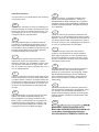
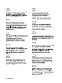
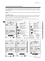

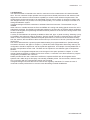


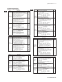
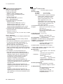
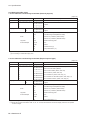
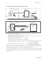
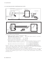
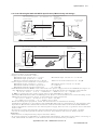


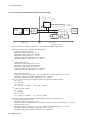
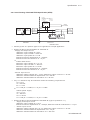
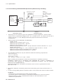
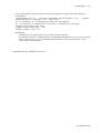
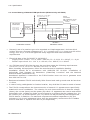
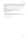
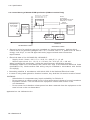
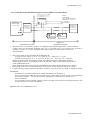
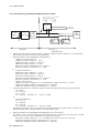
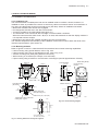
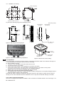
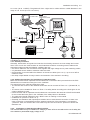
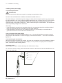
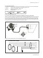
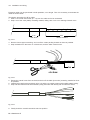
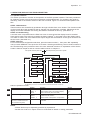
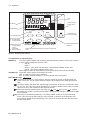
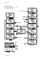
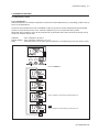
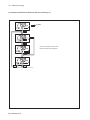
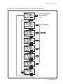
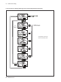
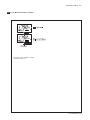
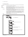
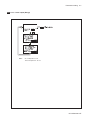
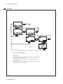
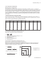
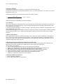
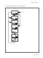

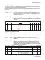
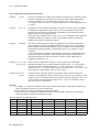
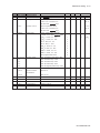
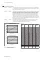
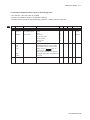
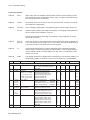

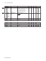
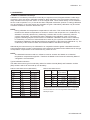
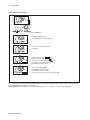
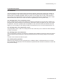
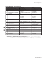

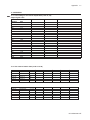
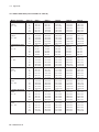
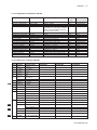
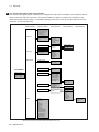
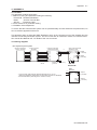
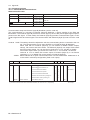
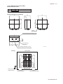
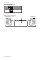
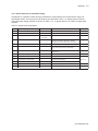
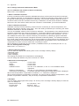
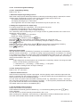
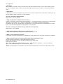
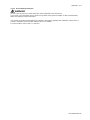
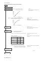
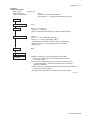
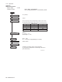
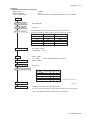
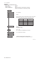
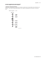


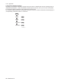


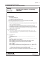
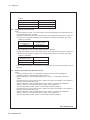
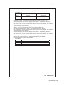
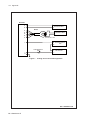
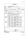
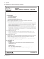
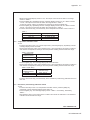
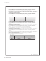
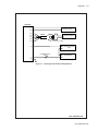
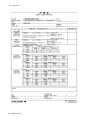
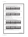
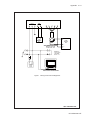
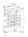

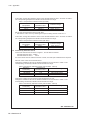
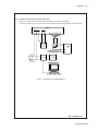
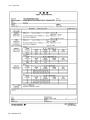
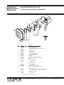
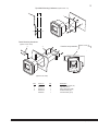
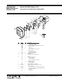
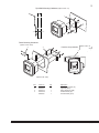

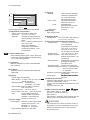
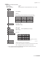


![ISC202SJ [スタイル:S1] 2線式電磁導電率伝送器](http://vs1.manualzilla.com/store/data/006585302_2-aa952b642369598fef037c616dd58a69-150x150.png)