1
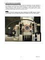
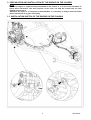
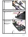
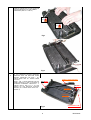
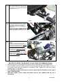
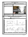
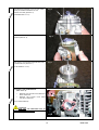
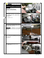
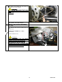
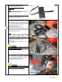
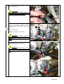
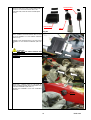
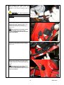
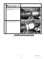
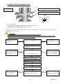
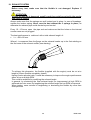
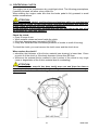
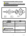
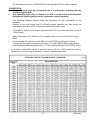
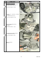
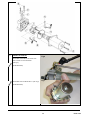
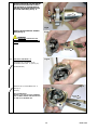
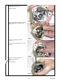
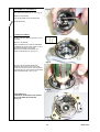
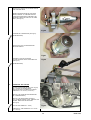
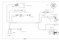
LEOPARD USA MY’09 125cc - RL - TaG ASSEMBLY INSTRUCTIONS & USER MANUAL 16/05/2011 MAN-055A INDEX PAGE GENERAL DESCRIPTION OF THE ENGINE 1 LEOPARD MY'09 ENGINE CHARACTERISTICS – OPERATIONAL LIMITS 2 Contents of packing 2 Engine serial number 4 Preparation and installation of the engine on the chassis 3.1 Installation sketch of the engine on the chassis 3.2 Install the water-cooling system 3.3 Exhaust header assembly 3.4 Preparation and installation of the motor mount 3.5 Install the carburettor 3.6 Install the engine on the chassis 3.7 Install the clutch cover with H.T. coil 3.8 Electric connections 3.9 Installation of the intake silencer 3.10 Install the exhaust system 5 5 6 10 10 11 13 14 15 20 21 4- Gasoline and Oil 22 5- Carburettor adjustment guide 23 6- Starting and stopping the engine 24 7- Engine break-in 25 8- RPM limiter 25 9- Intake silencer 25 10- Recommendations on the exhaust system 26 11- Centrifugal clutch 27 12- Instructions for the disassembly / reassembly of the clutch 28 13- Battery 29 14- Warnings on the electrical system 30 15- Sparkplug and thermal degrees 31 16- Choice of the best sprocket ratio 32 17- Replacement of the starter brushes 35 18- Scheduled maintenance 41 19- Troubleshooting 42 20- Engine and accessories preservation 43 21- Fastener torque table 43 wiring diagram 44 MAN-055A GENERAL DESCRIPTION OF THE ENGINE This engine of the "TaG" series (Touch and Go) has been expressly designed and developed for the powering of karts for hobby racing on closed tracks, destined for this specific purpose. When designing this new line of engines, the technical solutions already adopted for the high performance engines were used, in order to guarantee the highest reliability of components, when the operating limitations are respected. The motor is a single cylinder using the two stroke principle. The cylinder and the crankcase are in aluminium alloy. The pressed in liner is made of centrifugated cast iron, fully machined to guarantee the best possible stability. The head is separated from the cylinder and secured by studs. The crankshaft is built and supported by two ball-bearings. The crankshaft is of steel alloy, hardened and tempered , as is the connecting rod which runs on roller bearings. The digital ignition with capacitive discharge is fed by a magneto which generates the spark energy for the starting of the engine, supplies the advance timing through an integrated pick-up and recharges the battery. The ignition includes a digital electronic unit, the stator-rotor, the starter relay, the H.T. coil, a switch key assembly, and the wiring harness (with a 5A fuse) which connects the whole system. The electronic box which controls the advance, the rev. limitation and the engine start/stop logic , integrates the voltage regulator and the ignition circuit. The starter relay (Solid type SSR), protected from short-circuits, supplies the power for the electric starter and is controlled by the power pack. An RPM limiter, integrated in the power pack, prevents the engine from exceeding 17.000 RPM during use. The spark is generated also without a battery; it is therefore possible, in case of emergency, to start the engine with an external starter unit. With the starter key in “RUN” position, the starter activates a Bendix type gear which engages the starter ring assembled on the clutch. The engine is provided with an automatic dry centrifugal clutch with low maintenance and with interchangeable sprocket. The carburettor is a diaphragm Tillotson carburettor (Tillotson HL series) with integral fuel pump, filter and all position mounting capability. The battery (12 V - 9Ah) is a sealed, no maintenance battery and is supplied already preassembled, in the battery support box which can be easily adapted to all existing chassis. The exhaust, included in the supply, is already tuned for the best possible performance. The engine is supplied with a kit which includes the radiator, the pump, water hoses and whatever necessary for the assembly on the kart. 1 MAN-055A CHARACTERISTICS OF THE "LEOPARD" ENGINE – OPERATIONAL LIMITS The characteristics of the engine are the following : • Cycle: OTTO / 2 stroke • Original cubic capacity: 123.67 cc • Original bore : 54.00 mm • Max. theoretical bore: 54.28 mm • Stroke : 54.00 mm • Lubrification : Fuel / oil mix. 6% (16.1) • Induction : Reed valve • Carburettor: Membrane, Tillotson • Cooling : Water • Ignition : Digital / with integral rev. limiter • Battery charge: With integral generator • Electric start : 12V/0.30 Kw • Clutch : Automatic ,dry, centrifugal Operational limits : • Max. RPM: 17.000 RPM (with rev. limiter) • Min. water temperature: 45°c • Max.water temperature: 65°c ATTENTION: Never exceed the above limits, no obligation of IAME exists in case the above limits are exceeded. 1- • • • • • • • • • • • • • • • • • • • • • • • • • CONTENTS OF THE PACKING Each Leopard 125 MY '09 engine is supplied with the under shown accessories: EXHAUST SYSTEM Flexible Spring for flexible Exhaust fiber strip Exhaust manifold Exhaust muffler INDUCTION Tillotson carb. Intake silencer ELECTRICAL PLANT 12 V Battery – 9Ah Battery support Battery strip Battery fixing clamps Electronic box Starter relay H.T. coil Starting key assembly Fixing clamps NGK BR 10 EG spark plug Spark plug cap MISCELLANEOUS Clutch cover with coil Starter brushes kit (refill) Dual-Lock fixing strap WATER COOLING SYSTEM Radiator Radiator support kit Water hose k it Complete pump group Quantity 1 3 1 1 1 1 1 1 1 1 2 1 1 1 1 8 1 1 1 1 1 1 1 1 1 2 MAN-055A ACCESSORIES EXHAUST SYSTEM BATTERY WITH SUPPORT NGK SPARK PLUG CLUTCH COVER / H.T. COIL COMPLETE ELECTRIC ASSEMBLY STARTER BRUSHES KIT ADDITIONAL ENGINE PLATE TILLOTSON CARBURETTOR RADIATOR SUPPORT KIT WATER HOSE KIT INTAKE SILENCER COMPLETE PUMP GROUP RADIATOR 3 MAN-055A 2- MOTOR IDENTIFICATION NUMBER The official motor identification number can be found stamped in the front right part of the crankcase, next to the electric starter (see fig.) The number normally includes a letter followed by 4 digits (there can be exceptions in some special cases). Other numbers stamped on the crankcase or other surfaces of the motor refer to various manufacturing processes and do not identify the motor. NOTE: In case of need for spares and when contacting the IAME Support Centers, please always refer to the Motor Identification Number and to the motor model. 4 MAN-055A 3- PREPARATION AND INSTALLATION OF THE ENGINE ON THE CHASSIS NOTE: In case the engine is supplied already assembled on the chassis, it is at care of the assembler to follow these instructions. The final customer, in this case, can skip this section and can start reading from section 4. Whenever the engine or a component is disassembled, it is necessary to always follow the under shown instructions for proper reassembly. 3.1- INSTALLATION SKETCH OF THE ENGINE ON THE CHASSIS 5 MAN-055A 3.2- INSTALL THE WATER COOLING SYSTEM NOTE: To install the water pump belts it is necessary to remove the rear axle. 1 REINSTALL THE REAR AXLE AFTER HAVING INSERTED TWO BELTS SUGGESTION: INSTALL OTHER TWO BELTS AS SPARES AND FIX THEM WITH TAPE TO THE AXLE. 2 INSTALL THE WATER PUMP (1 SCREW M8x45 WITH WASHER AND NUT) ON THE PUMP BRACKET ON THE REAR CROSS RAIL (SEE FIG. 1). TORQUE AT 18÷22 Nm (160÷190 in-lb) Fig.1 IN CASE THERE IS NO BRACKET FOR THIS PURPOSE IT IS NECESSARY TO INSTALL THE PUMP ON REMOVABLE CLAMPS AVAILABLE IN DIFFERENT DIAMETERS (∅28/30/32mm). ASSEMBLE THE PUMP FIXING BRACKET ON THE CLAMP (N°2 SCREWS M6x12) AND PLACE THE CLAMPS ON THE REAR CROSS RAIL (N°2 SCREWS M6x25). INSTALL THE PUMP ON THE BRACKET (N°1 SCREW M8x45 WITH WASHER AND NUT – SEE FIG. 2). TIGHTEN BY HAND THE SCREW ON THE PUMP LETTING IT FREE TO ROTATE FOR THE ALIGNMENT AND TENSIONING OF THE BELTS. PUMP FIX. BRACKET VITE M8X45 VITE M6X12 Fig.2 SCREW M6X25 3 INSTALL ON THE AXLE THE DRIVING PULLEY (N° 2 CLAMPS AVAILABLE IN DIFFERENT DIAMETERS ∅30/35/40/50mm) ALIGNING ITS RACE WITH THE DRIVEN PULLEY (SEE FIG.3). FIX THE TWO CLAMPS WITH 2 SCREWS M5x22 (TIGHTEN AT 6÷ 8 Nm) (50÷70 in-lb). TIGHTEN THE TWO SCREWS M6x25 ON THE PUMP FIXING CLAMPS AND THE SCREWS M6x12 ON THE PUMP FIXING BRACKET. TIGHTEN AT 8÷10 Nm (70÷90 in-lb) SCREW M5X22 Fig.3 6 MAN-055A 4 INSTALL THE BELTS AND TENSION (SEE FIG. 4). TIGHTEN THE SCREW M8x45 TORQUE AT 18÷22 Nm (160÷190 in-lb) Fig.4 BEFORE INSTALLING THE RADIATOR PREASSEMBLE THE FOLLOWING COMPONENTS 5 INSERT THE 4 RUBBER DAMPENERS INTO THE FIXING HOLES ON THE RADIATOR (SEE FIG. 5). RUBBER DAMPENER Fig.5 6 - PLACE THE RADIATOR SUPPORT BRACKET BETWEEN THE RADIATOR FIXINGS BY TILTING ONE END AND INSERTING IT THROUGH THE RUBBER DAMPENERS (SEE FIG. 6) NOTE: OIL THE BRACKET ENDS AND THE RUBBER DAMPENER HOLES TO FACILITATE INSERTION. RADIATOR SUPPORT BRACKET Fig.6 7 MAN-055A - COMPLETE INSERTION OF THE RADIATOR SUPPORT BRACKET INTO THE RUBBER DAMPENERS (SEE FIG. 7 AND 8). Fig.7 Fig.8 7 FIX THE RADIATOR SUPPORT BRACKET INSERTING ALSO THE RADIATOR FIXING BRACKET (RADIATOR CAP SIDE – N°1 SCREW M6x90 AND N°1 SCREW M6x85 WITH NUT). INSTALL THE “L” SHAPE BRACKET ON THE LOWER RADIATOR CLAMP (AVAILABLE IN DIFFERENT DIAMETERS ∅28/30/32mm - 2 SCREWS M6x12) AND FIX IT TO THE TONGUE ON THE RADIATOR SUPPORT BRACKET (N°1 SCREW M8x20 WITH NUT SEE FIG. 9). RADIAT. FIXING BRACKET VITE M6X90 VITI M6X12 VITE M8X20 VITE M6X85 Fig.9 8 LOWER FIXING CLAMP MAN-055A PLACE THE RADIATOR FIXING CLAMP ON THE CHASSIS SIDE RAIL (BRAKE SIDE) (N°2 SCREWS M6x25). TIGHTEN THE BOLTS BY HAND (SEE FIG. 10). 8 Fig.10 PLACE THE RADIATOR SO THAT THE HOLE ON THE RADIATOR BRACKET AND ONE OF THE UPPER HOLES ON THE BEARING SUPPORT BOX, MATCH. (N°1 SCREW M8) – (SEE FIG. 11). ONCE YOU FIND THE CORRECT POSITION TIGHTEN THE M6x25 SCREWS ON THE CLAMP. TORQUE AT 8÷10 Nm (70÷90 in-lb) 9 Fig.11 10 THE KIT INCLUDES THREE RUBBER HOSES. - CONNECT THE FIRST HOSE TO THE FITTING ON THE RADIATOR INLET AND THE FITTING ON THE ENGINE OUTLET. TIGHTEN WITH STEEL CLAMPS ON BOTH SIDES. - CONNECT THE SECOND HOSE TO THE FITTINGS ON THE RADIATOR OUTLET AND THE PUMP INLET, TIGHTEN WITH STEEL CLAMPS ON BOTH SIDES. - CONNECT THE THIRD HOSE TO THE FITTINGS ON THE PUMP OUTLET AND THE ENGINE INLET, TIGHTEN WITH STEEL CLAMPS ON BOTH SIDES (SEE FIG. 12). Fig.12 • • • • BEFORE STARTING THE ENGINE FOLLOW THESE RECOMMENDATIONS: Unscrew the cap on the radiator and loosen the breather plug on the engine head. Fill the radiator until the water comes out from the plug on the head (there is no air in the system now) and the radiator is completely filled. Tighten the cap (the system contains appr. 1 lt. of water). It is advisable to put a small cup to recover water from the breather on the cap in case of boiling water. After the engine run-in, check the water level in the radiator and top up if necessary. 9 MAN-055A 3.3 EXHAUST HEADER ASSEMBLY NOTE: THE ENGINE IS SUPPLIED WITH THE EXHAUST GASKET AND NUTS ALREADY INSERTED. WHEN THE SHIPMENT IS MADE AN EXHAUST CARD BOARD COVER GASKET IS PROVIDED TO PROTECT THE INTERNAL PARTS. 3.3.1 REMOVE THE NUTS AND THE EXHAUST CARD BOARD COVER. Fig.1 3.3.2 MAKE SURE THE EXHAUST GASKET IS IN SEAT AND INSTALL THE EXHAUST HEADER (SEE FIG 1). 3.3.3. INSERT THE 3 WASHERS 6mm. 3.3.4 INSTALL THE THREE NUTS. TORQUE AT 9 ÷ 11 Nm (80 ÷ 100 in-lb) 3.4 12 POINT WRENCH 10 mm (OR OPEN WRENCH 10 mm) PREPARATION AND INSTALLATION OF THE MOTOR-MOUNT NOTE: ALL THE DIMENSIONS ARE IN MILLIMETERS 3.4.1 DRILL 4 HOLES (DIAM. 8.5mm) IN THE MOTOR-MOUNT. MOTOR-MOUNT PLANT VIEW 10 MAN-055A 3.4.2 BEFORE INSTALLING THE MOTOR-MOUNT, POSITION THE ADDITIONAL MOUNT PLATE ON THE CRANKCASE (SEE FIG. 2) Fig.2 3.4.3 INSTALL THE MOTOR MOUNT. MAKE SURE TO USE M8 ALLEN SCREWS WITH A LENGHT SUCH AS TO ENGAGE, IN THE CRANKCASE, A THREADED PORTION LENGHT OF 16÷19mm (THE SCREW MUST PROTRUDE FROM THE PLATE FOR 16÷19mm) (SEE FIG. 3 AND DRAW. PAG. 10) Fig.3 4 ALLEN SCREWS M8 – TORQUE AT 22÷24 Nm (190 ÷ 210 in-lb) (6 mm ALLEN WRENCH) 3.5 INSTALL THE CARBURETTOR 3.5.1 INSTALL THE GAS CABLE CLAMP ON THE SUPPORT (SEE FIG. 4) Fig.4 (12 POINT WRENCH 10mm) 11 MAN-055A Fig.5 3.5.2 REMOVE 2 SCREWS 3.5mm ON THE CARB. PUMP (IN CORRESPONDENCE OF THE THROTTLE LEVER) (SEE FIG. 5). (SCREWDRIVER 4.8 mm) 3.5.3 INSERT THE GAS BRACKET AND THE TWO SCREWS (SEE FIG. 6). Fig.6 Fig.7 3.5.4 INSTALL THE INTAKE SILENCER SUPPORT 2 SCREWS M5 X10 (SEE FIG. 7) (ALLEN WRENCH 3 mm) 3.5.5 INSTALL THE CARBURETTOR (SEE FIG. 8 / 9). REMOVE THE TWO M6 NUTS FROM THE INLET MANIFOLD. REMOVE THE PLASTIC PLUG FROM THE INLET MANIFOLD (10mm OPEN WRENCH) ATTENTION: MAKE SURE THAT THE PRESSURE HOLE ON THE GASKET IS NOT PLUGGED . Fig.8 12 MAN-055A ATTENTION: WHEN REPLACING THE CARB. GASKET ALWAYS MAKE SURE THAT THE GASKET IS INSTALLED SO THAT THE HOLE IN THE GASKET MATCHES WITH THE TWO PRESSURE HOLES IN THE CARB. AND IN THE CRANKCASE: OTHERWISE THE ENGINE WON’T START. Fig.9 INSTALL THE CARBURETTOR. N.2 NUTS M6 AND TWO WASHERS. TORQUE AT 6 ÷ 10 Nm (50 ÷ 90 in-lb) BEFORE GOING AHEAD WITH THE OPERATIONS DISASSEMBLE THE CLUTCH COVER WITH H.T. COIL BY REMOVING THE 3 SCREWS M6x30 ON THE CRANKCASE . (SEE FIG.10) Fig.9 A (ALLEN WRENCH 5mm) Fig.10 3.6 INSTALL THE ENGINE ON THE CHASSIS 3.6.1 POSITION THE ENGINE ON THE 2 OUTSIDE MAIN RAILS AND FIX THE MOTOR-MOUNT WITH THE TWO CLAMPS (SEE FIG.10) SUGGESTION: NEVER TORQUE COMPLETELY THE CLAMPS UNTIL THE CHAIN IS INSTALLED AND PROPERLY ALIGNED. Fig.11 3.6.2 CHECK THE ALIGNMENT OF THE ENGINE SPROCKET AND THE AXLE SPROCKET WITH A STRAIGHT EDGE . (SEE FIG.12) Fig.12 3.6.3 INSTALL THE CHAIN (PITCH: 7.775) . (SEE FIG.13) Fig.13 13 MAN-055A 3.6.4 MOVE THE ENGINE ON THE RAILS TO OPTIMIZE THE CHAIN TENSION . ATTENTION: THE PLAY OF THE CHAIN MUST BE APPR. 16mm (1/2 ÷ 3/4 inch) MEASURED IN THE SHOWN POINT (SEE FIG. 14) 15mm Fig.14 3.6.5 TORQUE THE CLAMP SCREWS 3.7 INSTALL THE CLUTCH COVER WITH H.T. COIL 3.7.1 INSTALL THE CLUTCH COVER WITH H.T. COIL (SEE FIG.15). TORQUE THE 3 SCREWS AT 8 ÷ 10 Nm (70 ÷ 90 in-lb) (ALLEN WRENCH 5 mm) ATTENTION: ALWAYS MAKE SURE THAT THE GROUND CABLE ALWAYS CONNECTS THE COIL WITH THE ENGINE. AN INADEQUATE GROUNDING COULD DAMAGE THE IGNITION BEYOND REPAIR. THE POSITION OF THE H.T. COIL HAS BEEN CHOSEN TO BE AS FAR AS POSSIBLE FROM THE EXHAUST AS THE EXCESSIVE HEAT COULD DAMAGE THE COIL BEYOND REPAIR. Fig.15 14 MAN-055A 3.8 Fig.16 ELECTRICAL CONNECTIONS (refer to the attached electrical schematic) NOTE: FOR A PROPER INSTALLATION FOLLOW THE UNDER SHOWN INSTRUCTIONS 3.8.1 INSERT THE BATTERY STRAP IN THE BATTERY SUPPORT (SEE FIG.16) 3.8.2 PLACE THE BATTERY SUPPORT BOX IN THE FRONT OF THE CHASSIS (UNDER THE FRONT FAIRING) AND FIX IT WITH THE CLAMPS TO THE LOWER STEERING COLUMN SUPPORT TUBES (M6x25 SCREWS– SEE FIG. 17). (1Omm SOCKET WRENCH) TORQUE AT 8 ÷ 10 Nm (70÷ 90 in-lb) THE SUPPORT BOX MUST BE FIXED WITH AT LEAST ONE BOLT FOR EACH CLAMP. FIX THE BOX WITH MORE THAN ONE BOLT DEPENDING ON THE TYPE OF CHASSIS. NOTE: THE BOX AND THE CLAMPS ARE PROVIDED WITH VARIOUS HOLES WHICH ALLOW INSTALLATION ON ALL KIND OF CHASSIS. Fig.17 3.8.3 INSERT THE BATTERY IN THE BOX AND FASTEN WITH THE BATTERY STRAP (SEE FIG. 18) POSITION THE BATTERY TERMINALS AS SHOWN ON THE FIGURE. ATTENTION: PAY ATTENTION NOT TO SHORT-CIRCUIT THE BATTERY TERMINALS AS THE BATTERY COULD BE DAMAGED BEYOND REPAIR. Fig.18 3.8.4 POSITION THE WIRING HARNESS STARTING FROM THE ENGINE AND ALONG THE RAIL, THE STEERING COLUMN AND UNDER THE FRONT PANEL FAIRING (SEE FIG. 19). TIGHTEN WITH PLASTIC CLAMPS. ATTENTION: NEVER LET THE HARNESS GET IN TOUCH WITH THE GROUND OR WITH ROTATING PARTS AS IT COULD BE DAMAGED BEYOND REPAIR. Fig.19 15 MAN-055A 3.8.5 CONNECT THE TERMINAL FROM THE IGNITION WITH THE 8 POLE TERMINAL ON THE HARNESS . (SEE FIG. 20) Fig.20 CONNECT THE ONE WAY TERMINAL FROM THE ELECTRIC STARTER WITH THE ONE WAY TERMINAL ON THE HARNESS (SEE FIG. 21). ATTENTION: MAKE SURE THAT THE FIXING TONGUES ARE PROPERLY INSERTED TO GUARANTEE THE BEST POSSIBLE CONNECTION OF THE TERMINALS . Fig.21 3.8.6 CHECK THE ELECTRIC STARTER FIXING (SEE FIG. 22). Fig.22 FIX THE HARNESS EYELET GROUND CABLE WITH THE EYELET TERMINAL TO THE STARTER SUPPORT, BY MEANS OF THE FIXING SCREW M6x35 (SEE FIG. 23). Fig.23 (ALLEN SCREW 5 mm) TORQUE AT 8 ÷ 10 Nm (70 ÷ 90 in-lb) ATTENTION: THIS OPERATION IS EXTREMELY IMPORTANT AS AN UNCERTAIN GROUNDING COULD DAMAGE THE ELECTRONIC BOX BEYOND REPAIR. 16 MAN-055A 3.8.7 COMPLETE THE HARNESS (SEE FIG. 24). FIXATION OF THE ATTENTION: NEVER LET THE HARNESS GET IN TOUCH WITH THE GROUND OR WITH A ROTATING PART AS IT COULD BE DAMAGED BEYOND REPAIR Fig.24 3.8.8 FIX THE SECOND HARNESS GROUND CABLE WITH THE EYELET TERMINAL (Ø 6.5mm), TO THE H.T. COIL, BY MEANS OF THE M6 NUT (SEE FIG. 25). Fig.25 (ALLEN SCREW 5mm) TORQUE AT 8 ÷ 10 Nm (70 ÷ 90 in-lb) ATTENTION: THIS OPERATION IS EXTREMELY IMPORTANT AS AN UNCERTAIN GROUNDING COULD DAMAGE THE ELECTRONIC BOX BEYOND REPAIR. 3.8.9 CONNECT THE H.T. COIL CABLE TO THE HARNESS TERMINAL (SEE FIG. 26). ATTENTION: FASTEN THE COIL CABLE WITH A PLASTIC CLAMP TO AVOID THAT EVENTUAL VIBRATIONS MIGHT DISCONNECT THE TERMINALS (SEE FIG. 27). Fig.26 Fig.27 17 MAN-055A FUSE HOLDER 3.8.10 CUT THE DUAL-LOCK FIXING STRAP AND ATTACH IT TO THE ELECTRONIC BOX, THE STARTER FUSE, AND THE FUSE HOLDER (SEE FIG.28). ELECTR. BOX RELAY Fig.28 3.8.11 CONNECT THE ELECTRONIC BOX TO THE 20 POLE TERMINAL IN THE WIRING HARNESS (SEE FIG. 29). CONNECT THE STARTER RELAY TO THE 4 POLE TERMINAL IN THE WIRING HARNESS (SEE FIG. 30). ATTENTION: MAKE SURE THAT THE FIXING TONGUES ARE PROPERLY INSERTED TO GUARANTEE THE BEST POSSIBLE CONNECTION OF THE TERMINALS . Fig.29 Fig.30 3.8.12 DRILL A Ø22mm HOLE IN THE SIDE OF FRONT FAIRING (ENGINE SIDE) AND INSERT THE STARTING ASSEMBLY (SEE FIG. 31). SECURE THE ASSEMBLY WITH THE THREADED RING NUT. Ø 22mm Fig.31 18 MAN-055A 3.8.13 CONNECT THE CABLE FROM THE STARTING ASSEMBLY WITH THE 8 POLE TERMINAL IN THE WIRING HARNESS (SEE FIG. 32). Fig.32 ATTENTION: MAKE SURE THAT THE FIXING TONGUES ARE PROPERLY INSERTED TO GUARANTEE THE BEST POSSIBLE CONNECTION OF THE TERMINALS . 3.8.14 ATTACH THE DUAL LOCK FIXING STRAP UNDER THE FRONT FAIRING (CLOSE TO THE STEERING COLUMN) AND PLACE THE ELECTRONIC BOX AND THE STARTER RELAY (SEE FIG. 33). Fig.33 NOTE: CLEAN AND DEGREASE THE FAIRING FIXING SURFACE WHERE THE STRAP IS TO BE PLACED TO GUARANTEE THE BEST POSSIBLE STRAP ATTACHMENT. 3.8.15 DRILL A FEW HOLES IN THE FAIRING TO ATTACH THE CABLES WITH PLASTIC CLAMPS (SEE FIG. 34). Fig.34 3.8.16 ATTACH THE DUAL LOCK FIXING STRAP UNDER THE FRONT FAIRING (CLOSE TO THE BATTERY) AND PLACE THE FUSE HOLDER (SEE FIG. 35). Fig.35 NOTE: CLEAN AND DEGREASE THE FAIRING FIXING SURFACE WHERE THE STRAP IS TO BE PLACED TO GUARANTEE THE BEST POSSIBLE STRAP ATTACHMENT. 19 MAN-055A 3.8.17 PLACE THE WIRING HARNESS BATTERY TERMINALS UNDER THE BATTERY STRAP (SEE FIG. 36). SUGGESTION: NEVER CONNECT THE BATTERY UNTIL YOU ARE READY TO START THE ENGINE. SEAL THE BATTERY TERMINALS WITH PLASTIC TAPE TO AVOID THAT EVENTUAL VIBRATIONS MIGHT DISCONNECT THE TERMINALS. Fig.36 3.9 3.8.18 SCREW THE SPARK CAP ON THE H.T.COIL CABLE (SEE fig. 37). Fig.37 3.8.19 FIX THE CAP TO THE H.T. CABLE WITH A PLASTIC CLAMP (SEE FIG. 38). Fig.38 • INSTALL THE SPARK PLUG. TORQUE AT 20 ÷ 26 Nm (175÷230 in-lb) • INSTALL THE CAP ON THE SPARK PLUG. INSTALL THE INTAKE SILENCER Fig.39 -MAKE SURE THAT THE FILTER HAS THE INLET HOLES TOWARDS THE UPPER SIDE AND THAT THE HOLES ARE NOT PLUGGED. -FIX THE FILTER ON THE CARB. WITH A STEEL CLAMP AND THE FILTER TO THE CHASSIS SIDE RAILS WITH PLASTIC CLAMPS (SEE FIG. 39 / 40). Fig.40 20 MAN-055A Fig.32 3.11 INSTALL THE EXHAUST NOTE: SEE SECTION 9 FOR THE RECOMMENDATIONS ON THE IDEAL EXHAUST LENGHT 3.11.1 INSTALL THE FLEXIBLE (L= 60mm FLEXIBLE COMPLETELY CLOSED) ON THE EXHAUST HEADER (SEE FIG. 41) AND ASSEMBLE THE EXHAUST MUFFLER. Fig.41 3.11.2 WIND THE STRAP IN REFRACTORY MATERIAL ROUND THE FLEXIBLE AND FIX IT WITH THE 3 SPRINGS (SEE FIG. 42). Fig.42 THE ENGINE IS READY TO BE STARTED 21 MAN-055A 4- GASOLINE and OIL Use leaded or unleaded Premium Gasoline (92 RON+MON) mixed with oil at 6% 2 (16:1). Use oils containing Castor Oil which guarantees an optimized lubrication at high temperatures. As on the other hand, use of Castor Oils creates gummy residues which give origin to carbon deposits, it is necessary to check and clean, at least every 5 ÷ 10 hours, the piston and the head. Our experience dictates use of oils such as: SHELL ADVANCE RACING M ELF HTX 909 ERG K KART 2T CORSE ERG K KART FORMULA Once the fuel tank is filled, make sure that gasoline reaches the carburettor before starting the engine. Never use the electric starter to suck the gasoline as this would discharge the battery. SUGGESTION: Disconnect the plastic tube on the carb. and the vent tube on the tank and pressurize the vent tube, until gasoline comes out from the tube on the carb. Make sure there is no air in the tube. Connect the tube on the carb. and on the vent. 22 MAN-055A 5- CARBURETTOR ADJUSTMENT GUIDE ( I ) THROTTLE SPEED SCREW ( H ) HIGH SPEED FUEL MIXTURE SCREW ( L) LOW SPEED FUEL MIXTURE SCREW * 1 T.O. RICH LEAN 1 ¼ T.O. ¾ T.O. 1 ½ T.O. * T.O. = TURNS OPEN Normally the correct setting of the mixture screws is the following: L (close the screw completely and then open): 1 ½ T.O. H (close the screw completely and then open): 1 ¼ T.O. Based on various factors as altitude, ambient temperature etc. it might be necessary to reset the carburettor to optimize the performance of the engine. - ATTENTION: Never lean too much as lean mixture will overheat engine and cause seizure Do not force H or L closed. It may damage the precision machined orifice and render the carb unserviceable. The adjustment of screw must be performed with warm engine. (H) Adjust T.O. from closed to approximately: (L) (I) Adjust T.O. from closed to approximately. a 1 ¼ T.O Close by further 1 ½ T.O. after contact with throttle lever. 1 ¼ .T.O. Start the engine and warm it. If RPM too high adjust L counterclockwise until clutch is disengaged. Turn c.c.w. until max. RPM is reached. Adjust further fractionally for rich idle. Trigger accelerator (L) If RPM decreases Slowly adjust clockwise If RPM increases Continue to turn clockwise until max. R.P.M. is reached. Adjust c.c.w. fractionally for rich idle. Trigger accelerator. Engine is now idling at max. attainable RPM or slightly lower on riche side. Adjust L counterclockwise until 2000 ÷ 2500 RPM is reached. Recheck L screw for optimum setting required. Adjust H until best possible free speed is reached. Turn clockwise for higher RPM. Counterclockwise for lower RPM. Bad adjust L slightly richer by 1/8 ÷ ¼ T.O. acceleration Good Return to idle and check acceleration for quick response and smooth pick-up. 23 Acceleration Engine is ready to operate. MAN-055A 6- STARTING AND STOPPING THE ENGINE Starting is achieved by the starting key. This is a 3 position key: 1- STOP (key can be removed) 2- KEY 3- RUN In STOP position the battery is disconnected and the engine stop signal is sent to the electronic box. In KEY position the battery is connected to the system and the stop signal is removed. In RUN position the battery is always connected and the electric starter, operation signal is sent to the electronic box. ATTENTION: The starting key assembly is supplied with two original keys. We recommend to separate the keys and to keep one in a protected place. In case of loss of both keys, it is necessary to replace the complete assembly. The starting procedure, from STOP position, is as follows: A) Turn the key to KEY position (this connects the battery). B) Turn the key to RUN position to start the engine (the electric starter is immediately disengaged when turning the key to KEY position, or when the electronic box detects an engine RPM higher than 1.500 RPM). C) When the engine is running, the key can be left both in the RUN or KEY position. We suggest, for pratical reasons, to turn the key to KEY position; this allows with a single tripping to stop the engine (STOP position) or to restart it in case the engine is stopped (RUN position). Note: - in case the engine is stopped with the key in RUN position, to restart it, turn the key to STOP position and then again to KEY and RUN position to activate the electric starter. - With the key in KEY or RUN position and if the engine is stopped, to start the engine an external starter unit can also be used. In case the engine cannot be started within 5 seconds (check that gas gets to the carb.) interrupt and try again after 15 seconds. Short and frequent tries are better than long ones. To stop the engine turn the key to STOP position both from KEY (1 tripping) or from RUN (2 trippings). 24 MAN-055A 7- ENGINE BREAK-IN The break-in of the engine must be performed following a few fundamental rules: 1. Adjust the carburetion. Start with an adjustment on the rich side. 2. Warm the engine gradually for about 5 minutes at half throttle,making some laps at low speed, gently closing and opening the carb. throttle (if a tachometer is installed never exceed 11.000 ÷ 12.000 RPM). Never keep the same RPM for a long time. 3. Progressively increase the speed of the kart for 5 minutes at ¾ throttle opening. Never keep the same RPM for a long time. 4. Increase the speed for 5 minutes, at max. speed on the twisty parts of the circuit and making the engine rich at half straight (cover with the hand for an instant the holes on the air filter, keeping the throttle wide open). ATTENTION: Once the break-in is over and the engine is cold, check the torque of the exhaust header nuts as, during the break-in, the nuts tend to become loose (refer to the attached table). 8- RPM LIMITATION The electronic box incorporates an RPM limiter which prevents the engine from exceeding 17.000 RPM. This limit cannot be exceeded otherwise the engine could be damaged by the extremely high RPM. ATTENTION: Do not keep the engine for a long time at the RPM at which the limiter is functioning. This would cause malfunctions on the induction and damage the reed valve. When choosing the sprocket ratio always refer to a maximum limit of 16500 RPM so that the incorporated limiter is not switched on continuously when the engine is running. 9- INLET SILENCER Make sure that the inlet holes on the filter are towards the upper side and that they are not plugged. Make sure that the clamp on the carburettor is not loosen and that the filter is well fastened to the chassis. Once a while, clean the inside from oil deposits. If necessary remove the rubber filter union and clean it with gasoline or solvent. 25 MAN-055A 10- EXHAUST SYSTEM Before every test, make sure that the flexible is not damaged. Replace if necessary. ATTENTION: In case the flexible is damaged, metallic particles could be sucked in the engine and cause a seizure. Always make sure that the springs are well hooked and in place. In case of breakage, replace the broken spring. Never race the kart without the 3 springs in place, as otherwise the exhaust pipe could vibrate beyond control. Every 10 ÷15 hours, open the pipe end and make sure that the holes on the internal counter cone are not plugged. The best performance is achieved with a total exhaust lenght of: L = 405÷410 mm. Where L is measured from the flange on the exhaust header up to the first welding on the first cone of the exhaust muffler (see drawing). To achieve this dimension, the flexible (supplied with the engine) must be cut at a lenght of 60mm (flexible completely closed). Having fixed a sprocket ratio, it could be necessary to improve the engine performance either at low or at high RPM. This could be achieved by modifying the exhaust lenght. In general, by shortening the total exhaust lenght an improvement at high RPM is achieved and vice versa, by lenghtening the exhaust lenght the low RPM is improved. When testing, never exceed in lenghtening or shortening the flexible by more than 5mm per time. 26 MAN-055A 11- CENTRIFUGAL CLUTCH The engine has a low maintenance dry centrifugal clutch. The following prescriptions, if carefully followed, will allow a long clutch life. When starting the engine make sure that the brake pedal is fully pressed to avoid sudden accelerations. ATTENTION: Once the engine is started, avoid useless accelerations which can overheat and deteriorate the clutch. Oil the chain before each test, immediately after each race or test, check the engine sprocket. Replace if necessary. A bad alignment of the engine sprocket with the axle sprocket or the lack of oil will damage the chain and sprocket. Check the clutch: Every 5 hours of use. When metallic noises are heard inside the clutch. If the kart dragging speed exceeds 6.000 RPM. Every time the clutch has overheated (presence of smoke or smell of burning). To check the clutch, you must remove the clutch cover and the clutch drum. When replace the clutch? whenever the thickness of the friction material (see drawing) is lower than 1.5mm on point A of the clutch or if the body diameter is lower than 82.5mm. Whenever the external friction material in the A portion of the clutch is very rough (wear or degradation of the friction material due to overheating). ATTENTION: In case the friction material has been totally worn out and there has been a metal contact between the clutch body and the clutch drum, it is necessary to replace the clutch drum. See drawing. 27 MAN-055A 12- INSTRUCTIONS FOR THE DISASSEMBLY / ASSEMBLY OF THE CLUTCH ATTENTION: The following operations can be performed by a skilled mechanic under the conditions to have available the dedicated tools shown on the text, otherwise it is necessary to apply to an Authorized Service Center. Refer to the following drawing during the operations. 1 Seeger ring 2 Washer 3 Roller cage 4 Sprocket 5 Clutch drum 6 Screw 7 Internal washer 8 Locking nut 9 Clutch body 10 Starter ring 11 Screw OPERATIONS TOOLS Clutch disassembly 1. Remove the clutch cover (3 screws M6). Allen wrench 5mm-T type 2. Remove seeger ring Pliers 3. Remove external washer, clutch drum with roller cage, inner washer 4. Apply the starter ring locking tool and remove the M20x1 nut securing the clutch body and starter ring. Locking tool: P.N. S884 30 mm socket 5. Apply clutch puller tool, remove body clutch and gear from crankshaft. Clutch puller tool: P.N. 10272-C 12 point wrench 12mm 6. Remove starter ring (3 screws M6) 12 point wrench 10 mm ATTENTION: turn clockwise as nut has left thread 28 MAN-055A Before assembling the clutch, wash with diluent the shaft taper, the starter ring and clutch drum. Clutch assembly 1. Install the starter ring on the clutch body by matching the 3 holes and the dragging pin (3 screws M6) 12 point wrench 10 mm (torque at 10 Nm) (90 in-lb) (apply “Loctite” on the threads) ATTENTION: make sure to always install the Ø 7 mm dragging pin as, otherwise the eventual kick backs could break the screws. 2. Install body clutch and starter ring. Apply “Loctite 641” for coaxial lockings. 3. Install clutch body fixing nut and starter gear by means of the starter ring locking tool Locking tool: P.N. S884 Allen wrench 30 mm. (torque at 100 ÷ 110 Nm ) (885 ÷ 975 in-lb) Pliers 5 mm- Allen wrench – T- Type (torque at 8 ÷ 10 Nm) (70 ÷ 90 in-lb) ATTENTION: turn counterclockwise as nut has left thread. 4. Install the internal washer . ATTENTION: install washer with bevel towards internal part of the engine. Clean the roller cage and grease it before installing it on the crankshaft. 5. Install the clutch drum and external washer 6. Install Seeger ring 7. Re-assemble the clutch cover (3 screws M 6) 13- BATTERY The battery (12 V – 9 Ah) is sealed and without maintenance. In order to lenghten the battery life it is necessary though to follow a few recommendations: When the tension drops below 12.6V it is necessary to recharge the battery. Max. allowed recharging current is 1.8A. The ideal recharge is achieved with an average charging current of 0.8 ÷ 1 A. (recharging time of appr.10 h.) and at an ambient temperature between 0° and 40°C. ATTENTION: An overcharge or an extremely quick charge with excessive current could damage the battery (the battery would tend to swell). Choose a battery charger with the following characteristics: Feed Tension: 90/250 Vac – 50/60 Hz Outlet Tension: 15 V full charge – 13.8 stand-by Max outlet current: 2A full charge During transportation or storage, the battery could loose its charge due to self discharge (0.1% max per day). Fully recharge battery before use. 29 MAN-055A ATTENTION: Always connect the - (negative) terminal before and the + (positive) terminal after. Always disconnect the battery in opposite order. Recharge the battery at least once every 6 months. Never let the battery tension dropping under 8V, as whenever it drops under this limit, the battery cannot be used any longer and it has to be replaced. Never put the battery in contact with solvents, gasolines, oils, plastifiers or rags containing such elements. The external case of the battery could be damaged. Never press or bend or overheat (by welding) the battery terminals. Other recommendations Pay attention not to have free fires upon or around the battery. Never short-circuit the terminals. Never open the battery or throw it in the fire. In case the electrolite (diluted Sulfuric acid) gets in contact with skin or clothes, immediately wash with water. In case it gets in touch with eyes, wash and apply for medical assistance. Carefully check the external case of battery and replace in case of breakages, swellings of the case or of battery cover. Before use, clean the battery from dust and check that the terminals are not oxidyzed or damaged. When the battery comes to an end never throw it in the garbage but deliver it to an authorized disposer. 14- WARNINGS ON THE ELECTRICAL SYSTEM We are here listing the main warnings on the electrical system. Please keep this in mind during the whole life of the engine. ATTENTION: If these prescriptions are not followed the electrical system and the engine could be damaged beyond repair. No obligation of IAME exists in this case. 1) 1) Please turn the key to STOP position every time the engine is stopped. If the key is left in KEY position, for a long time, even if the engine is stopped, the battery would be discharged completely. 2) Never disconnect the ground cables with eyelets when the engine is in operation. 3) Disconnecting the battery when the engine is in operation DOES NOT increase the engine performance. Vice versa, the ignition advance could become very irregular at low RPM thus reducing the performance. 4) To fasten the eyelet terminal (groundings) of the wiring harness always use flat or open washers. Never use tab washers. 5) When disconnecting the connectors, always press the fixing tongues. Always pull the connectors to disconnect. NEVER PULL THE CABLES. 6) The electronic box and the starting relay must always be installed with their connector towards the bottom to avoid back water, dampness or dirt in the connector body. 7) Always fix correctly the H.T. coil with both screws, make sure that the laminations pack on H.T. coil is connected to the engine with the grounding cable. The eyelet connector must be directly in contact with the laminations pack on the H.T. coil. 8) Never use H.T. coils different than the original coil on the engine. Use of different coil may cause damages to the electronic box. 30 MAN-055A 9) The digital assembly needs use of a resistive spark plug cap or spark plug. The resistor value must be equal or higher than 5 Kohm. Avoid use of resistive H.T. cables. 10) The electrical system is protected against battery polarity reversal. When reversing the connectors on the battery, the protection circuit activates the fuse as soon as the key is on KEY or RUN position. The fuse must then be replaced. 11) Replace the fuse after having disconnected both terminals on the battery. Only use 5A strip fuse. Use of fuses with higher amperage might damage the electronic box whenever the battery polarity is reversed. 12) Only use sealed lead type batteries as specified by IAME. Only use 12V. batteries. 13) Always disconnect the battery from the electrical system when recharging the battery with an external battery charger, otherwise the internal voltage regulator could be damaged. 14) DO NOT connect batteries in parallel; this might cause explosions and damages to the operator. The recharge of the battery, in normal conditions, is guaranteed by the electrical system. A few minutes of engine in operation are sufficient to recover the energy lost when starting the engine. 15) In case the battery must feed other users (Tachometer, Telemetry etc…), first contact IAME to check the recharge capacity of the system. 16) Modifications, interventions and additions to the original electric system might cause malfunctions. No obligation of IAME exists in this case. 15 - SPARK PLUG AND THERMAL DEGREE The engine is supplied with a standard NGK BR10EG spark plug which represents a good compromise between the needs of a good break-in and the racing needs in normal conditions. Use of different spark plugs is possible and, as a general information, we are attaching a correspondence list among spark plugs of other brands based on thermal degree which represents the capacity of the spark plug to dissipate the internal heat. The colour of the various parts of the spark plug more exposed to the combustion flames gives a good indication on the adequacy of the thermal degree and on the carburetion. It is necessary though to understand which of the two parameters has to be changed and only the experience tells how to identify the most proper thermal degree of a spark plug as lean or rich mixtures can generate the same final look which can also be achieved with a hot or cold spark plug. See table: An excessively warm symptoms listed aside spark plug shows the ATTENTION: Always use a warmer than standard spark plug with cold or rainy climates. Colour of the insulator end from yellow grey to dark brown for mixtures respectively lean or rich. the Insulator end and electrodes covered with black shady soot. Ignition difficulties. Note: a wet or oily electrode could also mean an excessively rich mixture. A correct thermal degree shows An excessively cold symptoms, listed aside. spark plug shows Extremely clear color, porous look and calcification of the electrodes and of the internal insulation. Irregularities in the ignition, preignition and detonation with tendency to perforate the top of the piston. Note: Some of these symptoms can be achieved with lean mixtures. ATTENTION: Always use a colder than standard sparkplug with hot climates. 31 MAN-055A COMPARISON TABLE BASED ON THE THERMAL DEGREE HOT BOSCH WO8CS WO7CS WO6CS NGK BR9EG BR10EG BR11EG CHAMPION N54R N52R COLD 16- CHOICE OF THE BEST SPROCKET RATIO The life of an engine depends upon many factors but most of all upon the speed at which the engine is operated. If an engine is normally operated at speeds higher than what recommended by the manufacturer, the wears and stress of the various components (con-rods, roller cages, bearings etc.) will be such as to drastically reduce the life of the engine itself. It is therefore extremely important that the user respects the operating limits imposed by the manufacturer. The operating limit for the Leopard MY'09 engine is 17.000 RPM and the RPM limiter is calibrated at this value. ATTENTION: Never exceed the above limit. No obligation of IAME exists in case the above limit is exceeded. In case the user wishes to optimize on the track the sprocket ratio in order to achieve the best possible performance, without abusing the engine, follow the under shown recommendations. The engines are supplied with a 10 or 11 teeth sprocket (pitch: 7.775mm). Table 1 shows the various ratios between the sprocket on the axle and the engine sprocket given the different axle sprockets. Tab.1 Sprocket ratio Teeth n° - Engine sprocket Sprocket ratio Teeth n° - Engine sprocket Teeth n° axle sprocket 10 11 Teeth n° axle sprocket 10 11 72 73 74 75 76 77 78 79 80 81 82 7,20 7,30 7,40 7,50 7,60 7,70 7,80 7,90 8,00 8,10 8,20 6,55 6,64 6,73 6,82 6,91 7,00 7,09 7,18 7,27 7,36 7,45 83 84 85 86 87 88 89 90 91 92 8,30 8,40 8,50 8,60 8,70 8,80 8,90 9,00 9,10 9,20 7,55 7,64 7,73 7,82 7,91 8,00 8,09 8,18 8,27 8,36 32 MAN-055A For the operaton limit of 16.500 RPM the following table N°2 has been prepared SUGGESTION: During the track tests we recommend use of a tachometer recording the max obtained engine RPM. Use sparkplug caps with a resistance of 5KΩ to avoid eventual interferences between the engine ignition and the tachometer and/or telemetry. The following example should clarify the procedure for the optimization of the sprocket. Assume to use the engine with Z=10 teeth engine sprocket and that during the preliminary track tests a Z=72 teeth axle sprocket has been used. From table 1 with Z=10 as engine sprocket and Z=72 on the axle sprocket, a ratio of 7.20 is found. Make a few laps on the track and, let us assume that you read 14.000 max engine RPM. From the table 2 to achieve a max RPM of 16.500 RPM (operating limit for the Leopard MY'09 engine) a sprocket ratio from 8.37 and 8.60 should be used (having used,during the tests,a sprocket ratio of 7.2 and having achieved 14.000 RPM max.). From table.1, with these values, a sprocket ratio of 10:84 / 10:86 should be used or, having a Z=11 on the engine sprocket, a ratio 11:92 should be used. SPROCKET RATIO TO ACHIEVE MAX. 16500 RPM Engine Max RPM during tests Sprocket Ratio 17- REPLACEMENT OF THE STARTER BRUSHES 33 MAN-055A OPERATIONS 1. PICTURES DISASSEMBLE THE STARTER - UNLOOSE THE SCREW M6 X30 ON THE STARTER SUPPORT (See Fig.1). (5mm ALLEN WRENCH T TYPE ) Fig.1 - REMOVE THE ADDITIONAL STARTER SUPPORT 3 SCREWS M6X25 (See Fig.2). Fig.2 (5mm ALLEN WRENCH T TYPE) - REMOVE THE STARTER SUPPORT 4 SCREWS M6x35 (See Fig.3). Fig.3 (5mm ALLEN WRENCH T TYPE) - TO REMOVE THE STARTER, UNLOOSE 3 SCREWS M6x35 (See Fig.4). (5mm ALLEN WRENCH T TYPE) Fig.4 - EXTRACT STARTER (See Fig.5). Fig.5 34 MAN-055A 2. OPENING THE STARTER - UNSCREW THE SCREW M4 FIXING THE INPUT CABLE TO THE STARTER Fig.6 Fig.1 (see Fig.6) (SCREWDRIVER) - UNSCREW THE 3 SCREWS M5 “C” (See Fig.7) Fig.7 (SCREWDRIVER) 35 MAN-055A - REMOVE DRUM FROM STARTER KEEPING ROTOR IN ITS SEAT (BE SURE TO HOLD THE ROTOR ON ITS TOOTHED SIDE TO PREVENT THE BRUSHES FROM FALLING OUT FROM THEIR SEAT) (see Fig . 8) Fig.4 Fig.8 - EXTRACT ROTOR FROM THE STARTER HEAD (see Fig. 9) Fig.9 ATTENTION: WHEN EXTRACTING THE ROTOR, THE BRUSHES MAY SPRING OUT FROM THEIR SEATS. 3. REPLACING THE BRUSH “A” Fig.10 -UNSCREW THE 2 SCREWS M4 "D" RETAINING THE PLATE “E” (see Fig.10). (SCREWDRIVER) Fig.11 -REMOVE THE LITTLE RUBBER CAP “F” (see Fig.11). (PLIERS) OUR SUGGESTION: SLIGHTLY OIL THE TIN PLATE TERMINAL END, TO MAKE EASIER THE EXTRACTION OF THE LITTLE RUBBER CAP. 36 MAN-055A -REMOVE SILICONE FROM BRUSHES WITH A SCREWDRIVER (see Fig. 11) -REMOVE SPRINGS Fig.12 - MAKING PRESSURE EXTERNALLY ON THE TIN PLATE TERMINAL, REMOVE BRUSH. (See Fig. 13) Fig.9 Fig.13 - INSTALL NEW BRUSH TERMINAL (See Fig.14). - PLACE THE LITTLE RUBBER CAP ON THE TERMINAL. Fig.14 - REINSTALL THE PLATE AND FIX IT WITH HE 2 SCREWS M4 (See Fig.15). (SCREWDRIVER) Fig.15 37 MAN-055A 4. REPLACEMENT OF THE BRUSH “B” Fig.16 - UNLOOSE RHE SCREW M3 “G” (See Fig.16) - EXTRACT THE BRUSH - FIX THE NEW BRUSH WITH SCREW M6 (SCREWDRIVER) 5. CLOSING THE STARTER - INSERT THE NEW BRUSH SPRING "A" INTO ITS SEAT. - INSTALL THE BRUSH. - KEEP THE BRUSH IN PLACE BY PRESSING TOWARDS THE OUTER AND CLAMP IT WITH AN IRON WIRE BENT AS A HOOK. REPEAT THE SAME PROCEDURE TO INSTALL THE BRUSH "B" (See Fig.17). Fig.17 - INSTALL THE ROTOR BETWEEN THE BRUSHES AND CHECK THAT THEY ARE ALWAYS IN CONTACT WITH THE CYLINDRIC COPPER PART OF THE ROTOR, EVEN WHEN THEY ARE RELEASED (See Fig.18). Fig.18 OUR SUGGESTION: TO IMPROVE THE BRUSHES LIFE, SECURE THE LITTLE WIRES WITH SILICONE (See Fig.19). Fig.19 38 MAN-055A - CHECK THAT O-RING "H" IS INSTALLED ON THE STARTER HEAD. - INSERT STARTER DRUM ON THE HEAD BEING CAREFUL TO PREVENT ROTOR FROM ROTATING AND TO PREVENT THE BRUSHES FROM FALLING OUT OF THEIR SEAT (see Fig. 20). Fig.20 - TORQUETHE 3 SCREWS M5 (see Fig.21). (SCREWDRIVER) - CHECK THAT THE STARTER ROTOR ROTATES FREELY. Fig.21 - CONNECT THE INPUT WIRING TO THE STARTER WITH THE SCREW M4 (see Fig.22). Fig.22 (SCREWDRIVER) 6. ASSEMBLING THE STARTER - PLACE THE STARTER IN SEAT (see Fig.23). OIL O-RING TO MAKE EASIER INSTALLATION N°3 SCREWS TCH M6x35 TORQUE AT A 8÷10 Nm ( 70÷90 in-lb ) - INSTALL THE STARTER ON CRANKCASE (N°4 SCREWS M6x35). - INSTALL THE ADDITIONAL SUPPORT (N°3 SCREWS M6X25) AND TORQUE THE SCREW M6X30 ON THE SUPPORT (see Fig.23). (5mm ALLEN WRENCH T- TYPE) Fig.23 TORQUE ALL THE SCREWS AT A 8÷10 Nm (70 ÷ 90 in-lb) 39 MAN-055A 18- SCHEDULED MAINTENANCE Following some simple maintenance standards will allow the engine to perform more reliability and have a longer life. SCHEDULE Before using After use Every 5 ÷ 10 hours Every 20 hours COMPONENTS ACTIONS AND COMMENTS Exhaust flexible Exhaust spring Exhaust strap Muffler Engine sprocket Check status Check status Check status Check status and fixing Check wear Check alignment with axle sprocket Engine chain Check status tensioning and oil chain Battery Check status and charge Cables & connectors Check status and connections Grounding of engine Check status and connections and electronic box Engine mount and Check torques clamps Battery Disconnect Chain Check status and oil chain Engine External cleaning Bendix assembly Remove cover (see fig.) and clean internally Exhaust muffler Inlet silencer Engine head Clutch Piston and con-rod assembly Crankshaft Ball bearings 40 Remove muffler end, clean Open, clean Open, clean Open, check status of parts Check and replace worn parts Check and replace worn parts Check and replace worn parts MAN-055A 19- TROUBLESHOOTING Below are some common faults, their probable causes and suggested remedy: FAULTS PROBABLE CAUSES Starter will not crank when Bad connections on starter cables turning the key to RUN position Bad grounding Interruption on fuse Damaged cables Battery connections loose Battery discharged Starter failure Electronic box or relay failure Starter cranks but engine won't Bad connections on cables start when turning the key in RUN position Bad H.T. coil connection or coil failure Bad H.T. coil grounding Electronic box or ignition failure Wet spark plug Malfunction on induction system Engine starts but it stops after a Bad cable connections few seconds when turning the key in RUN position Electronic box or ignition failure Bad carburettor adjustment (L screw) The starter cranks also after the Electronic box failure engine is running. Bad carb idle adjustment Rough idle ( screw I) Bad compression Drop in engine performance Bad carburettor adjustment Insufficient gas flow Dirty inlet silencer Overheating of clutch Burning smell, smoke Clutch engages at too high RPM Excessive wear of friction material Flexible damaged Exhaust too noisy Springs damaged or lost Insulating strap damaged Damaged exhaust header 41 REMEDY Check and tighten Check connections and tighten Replace (5A) strip fuse, after checking for eventual reversal of battery polarity. Replace Check and tighten Recharge battery or replace Overhaul starter Apply to Authorized Service Center Check connectors. Check/Replace Check grounding Apply to Authorized Service Center Replace Check status and connection on fuel pipe Replace gaskets and membranes on carburettor Check reed petals. Replace if necessary Check stator connector Apply to Authorized Service Center Check carburettor adjustment (see sect. 5) Apply to Authorized Service Center Check carburettor adjustment (see sect. 5) Check piston Check carburettor adjustment (see sect.5) Check fuel flow lines and inlet filter Check and clean Check clutch (see Sect. 11) Check clutch (see Sect. 11) Check and replace if necessary MAN-055A 20- ENGINE PRESERVATION When engine is to remain unoperative for a long period it must be preserved as follows: Disconnect the battery and charge it periodically (see Sect. 12) Disconnect carburettor and clean it Seal with tape the engine inlet and exhaust The external of the engine must be cleaned. Spray with protective oil the steel parts subject to oxidation. Keep the engine in a dry ambient. 21- TORQUE VALUES 42 MAN-055A 43 MAN-055A