1
FMC32 Control Software User's Manual
― Blank Page ―
YA7175-0/0
FMC32 Control Software User's Manual
YA7175-0/0
Table of Contents
1. Preface...................................................................................................................................................... 1
1-1. FMC32's function............................................................................................................................ 2
2. Basic operation procedure of this software ......................................................................................... 3
2-1. Start software .................................................................................................................................. 3
2-2. Create a project .............................................................................................................................. 4
2-3. Load project .................................................................................................................................... 5
2-4. Save a project ................................................................................................................................. 5
2-5. Load a project used recently ....................................................................................................... 6
2-6. Exit software ................................................................................................................................... 6
3. Design the data of pattern window ........................................................................................................ 7
3-1. Set the maximum speed................................................................................................................ 8
3-2. Set the initial speed ....................................................................................................................... 8
3-3. Set the number of positioning pulse.......................................................................................... 8
3-4. Set the time for acceleration........................................................................................................ 8
3-5. Set the time for deceleration ....................................................................................................... 8
3-6. Select acceleration / deceleration characteristics .................................................................. 9
3-7. Magnification ratio option ............................................................................................................ 9
3-8. Set a constant speed ..................................................................................................................... 9
3-9. Set reference clock ........................................................................................................................ 9
3-10. Set operational direction ............................................................................................................ 9
3-11. Set operation mode.................................................................................................................... 10
3-12. Confirmation of setting value ...................................................................................................11
3-13. Select operation mode .............................................................................................................. 13
3-14. Select characteristics of acceleration and deceleration. .................................................. 14
3-15. Adjustment of magnification ................................................................................................... 15
3-16. Switch the operation direction ................................................................................................ 16
3-17. Switch excitation ........................................................................................................................ 16
3-18. Start operation ............................................................................................................................ 16
3-19. Stop operation ............................................................................................................................ 16
3-20. Register and confirm operation pattern ................................................................................ 17
3-21. Save the registered pattern data............................................................................................. 19
- C1 -
FMC32 Control Software User's Manual
YA7175-0/0
3-22. Import pattern data .................................................................................................................... 19
3-23. Environment setting .................................................................................................................. 20
3-24. STA input in PC control mode ................................................................................................. 23
4. Design the data of pattern Window...................................................................................................... 24
4-1. FMC32 command .......................................................................................................................... 25
4-2. Command input to editor............................................................................................................ 29
4-3. Save a program............................................................................................................................. 34
4-4. Import a program.......................................................................................................................... 34
4-5. Check description content and assemble............................................................................... 35
4-6. Run(Simulation) ....................................................................................................................... 36
4-7. Execution(Real operation) ..................................................................................................... 38
5. Inching operation................................................................................................................................... 41
5-1. Continuous operation.................................................................................................................. 41
5-2. Positioning operation .................................................................................................................. 41
6. Access to Serial EEPROM .................................................................................................................... 42
6-1. Write to EEPROM.......................................................................................................................... 42
6-2. Read data in EEPROM ................................................................................................................. 43
7. Language selection ............................................................................................................................... 43
8. Adjustment mode .................................................................................................................................. 44
9. Control PCD2112 directly...................................................................................................................... 46
9-1. Function description of the main window............................................................................... 46
9-1-1-1. Set value to register ............................................................................................................................ 46
9-1-1-2. Select radix of register value............................................................................................................... 46
9-2. Advanced setting of registers ................................................................................................... 48
9-3. Select operation directive to FMC32 ........................................................................................ 52
9-4. Confirm the detail of registers................................................................................................... 53
10. Meaning of messages and solution................................................................................................... 55
- C2 -
FMC32 Control Software User's Manual
YA7175-0/0
1. Preface
Thank you for considering our FMC32, a compact controller with integrated driver.
Before you read this manual, please install required software and hardware according to the PUSB3503
user's manual.
The product that you purchased contains the PCD2112: a pulse control LSI for serial-bus control. With it
you can design execution sequence programs and write designed execution sequence program to the
FMC32 using PUSB-3503. Before writing them to FMC32, you can also inspect and confirm the
program on your PC.
By using this software, you can monitor the contents of all register of PCD 2112 in real time. You can
use this function to understand PCD2112 thoughtfully.
The FMC32 is equipped with a CPU which allows you to repeat the execution sequence program that is
written to FMC32, automatically. If you use a motor and a driver additionally, you can confirm operation
in more detail.
This manual describes how to use the software to operate the PUSB-3503 and the FMC32 together.
Please read this manual thoroughly to use this product's functions.
This manual does not describe the followings.
- FMC32 hardware function
- PUSB-3503's function and handling method
- The contents of PCD2112's register
Additionally, please use the following user's manual.
- Compact controller with integrated driver FMC32 Hardware, User's manual (Document No. YA7174)
- USB to 4- wire serial conversion unit PUSB-3503, User's manual (Document No. YA7176)
- Pulse Control LSI PCD2112 for serial bus controls, User's manual (Document No. DA70115)
-1-
FMC32 Control Software User's Manual
YA7175-0/0
1-1. FMC32's function
FMC32 has two modes: "PC control mode" that is controlled by a PC and "Standalone mode" that is
used for standalone . This manual describes the software used on a PC.
1-1-1. PC control mode
When the FMC32 connects with PUSB-3503 and is powered on, the FMC32 is in PC control mode.
Even if the PUSB-3503 is removed while operating in PC control mode, the mode does not change to
Standalone mode.
In PC control mode, the FMC32 will not run a program written in the FMC32. To get the FMC32 to work
in this mode, operational directions from a PC are required.
1-1-2. Standalone mode
If the FMC is powered on without the PUSB-3503, the FMC 32 is in stand-alone mode. The FMC32 in
stand-alone mode will automatically run a written program. If the PUSB3503 is connected to the FMC32
while the FMC32 is running in standalone mode, the mode does not change to the PC control mode.
-2-
FMC32 Control Software User's Manual
YA7175-0/0
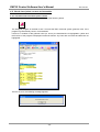
2. Basic operation procedure of this software
2-1. Start software
First of all, confirm that FMC32 is connected with your PC.
Then, double-click the following software icon.
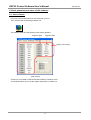
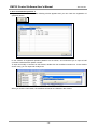
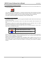
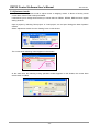
The software starts and the following main window appears.
Register name
Register value
Register value display
[Main window]
"PCD2112" is mounted on FMC32 and this PCD2112 controls a motor.
This windows allows you to set the register information of "PCD2112".
-3-
FMC32 Control Software User's Manual
YA7175-0/0
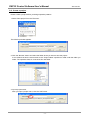
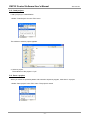
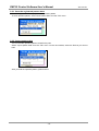
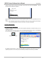
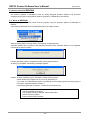
2-2. Create a project
Please create a project before you design operation patterns.
1. Select "New project" from the File menu.
The following window appears.
2. Click the "Browse" button and select the folder where you want to save the project.
A new folder that has the same name as the "Project Name" specified is made under the folder you
select. The operation data, etc is saved in this new folder.
3. Input a project name.
After you input a project name, click the "OK" button.
-4-
FMC32 Control Software User's Manual
YA7175-0/0
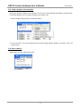
2-3. Load project
Load a project you created before.
1.Select "Load Project" from the "File" menu.
The window to select a project appears.
2. Select a project.
The extension of the project is ".npf".
2-4. Save a project
When you create an operation pattern and execution sequence program, save them in a project.
1.Select "Save project" in the "File" menu. The project is saved.
-5-
FMC32 Control Software User's Manual
YA7175-0/0
2-5. Load a project used recently
Among the projects edited by this software, the five most recent projects are listed for quick access.
From these projects, you can select one project you want to use.
1. Select "Project used recently" from the File" menu.
2. In the sub-menu, up to five projects that are used recently appear. Select one project. Then, the
project opens.
2-6. Exit software
Select "Exit" from the "File" menu to exit.
-6-
FMC32 Control Software User's Manual
YA7175-0/0
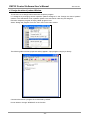
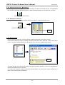
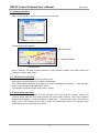
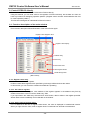
3. Design the data of pattern window
Design operation you want to do using FMC32.
Select "Design the data of pattern" from the "Tool" menu and the following window appears.
Using this window, PCD2112 mounted in FMC32 is controlled simply. At that time, RMD and RENV1
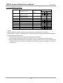
registers show default values as follows.
Register
Default value
RMD
1085 h
RENV1
008862C4 h
Note
Even though FMC 32 is in a mode waiting for start, if
you confirm operation using the "execute" button in the
above window, the waiting mode stops temporarily and
starts operation. After the operation is completed, the
mode return to the waiting mode.
This setting is fit for FMC32's hardware.
-7-
FMC32 Control Software User's Manual
YA7175-0/0
3-1. Set the maximum speed
Set the maximum speed at the completion of acceleration in pps. Only
whole numbers can be used.
3-2. Set the initial speed
Set an initial speed at the start to accelerate
Only whole numbers can be used.
3-3. Set the number of positioning pulse
Set the number of output pulses in positioning operation.
Only whole numbers can be used.
3-4. Set the time for acceleration
Set the acceleration time for acceleration operation in msec.
Only whole numbers can be used.
3-5. Set the time for deceleration
Set the deceleration time for deceleration operation in msec.
Only whole numbers can be used.
-8-
FMC32 Control Software User's Manual
YA7175-0/0
3-6. Select acceleration / deceleration characteristics
Select characteristics for acceleration / deceleration operation.
Uncheck: linear acceleration operation
Check: S-curve acceleration/deceleration
3-7. Magnification ratio option
Uncheck: Magnification ratio that is smaller than 1 becomes 1
even if the magnification ratio is appropriate.
Check: Magnification ration that is smaller than 1 is effective.
3-8. Set a constant speed
Check to operate at constant speed without acceleration and
deceleration.
Specify a speed in the "initial speed" field.
3-9. Set reference clock
Set a clock frequency to be provided to PCD2112.
FMC32 uses 9.8304MHz clock frequency (Do not change this
default value).
3-10. Set operational direction
To click this button, you can specify operation direction.
"+" means CW direction and "−" means CCW direction.
-9-
FMC32 Control Software User's Manual
YA7175-0/0
3-11. Set operation mode
You can select among the following six operations.
1. Continuous operation
2. Origin return operation
3. Origin escape operation
4. EL escape operation
5. Positioning operation
6. Timer operation
Regarding the details of each operation, please refer to PCD2112
User's manual (Document Nol. DA70115).
- 10 -
FMC32 Control Software User's Manual
YA7175-0/0
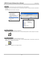
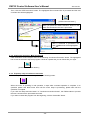
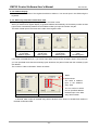
3-12. Confirmation of setting value
Using the setting values, the PCD 2112 register values appears.
Based on these setting values, actual operation speed and operation time will be calculated and be
shown. There are instances when the set values cannot be operation be achieved due to operation
specifications.
Number of pulses at the maximum speed
Magnification rate
Number of pulses when accelerating
Maximum speed
Initial speed
Number of pulses Deceleration
while Decelerating time
Register setting value
of PCD2112
Operation time at the maximum speed
Acceleration
time
3-12-1. Confirm the register setting value
Register setting value to be set for PCD2112 is shown in hex notation.
When you click the "Execute" button, these values are written to each register of PCD2112 and
operation starts.
3-12-2. Confirmation of the maximum speed
If the value shown in the "Register setting value of PCD2112 " field is set, the actual maximum speed
will be calculated and shown as a decimal.
3-12-3. Confirmation of the initial speed
When the value shown in the "Register setting value of PCD2112" field is set, the actual initial speed will
be calculated and shown as a decimal.
- 11 -
FMC32 Control Software User's Manual
YA7175-0/0
3-12-4. Confirmation of acceleration time
When the value shown in the "Register setting value of PCD2112" field is set, the actual acceleration
time will be calculated and shown as a decimal.
3-12-5. Confirmation of deceleration time
When the value shown in the "Register setting value of PCD2112" field is set, the actual deceleration
time will be calculated and shown as a decimal.
3-12-6. Confirmation of time at the maximum speed
When the value shown in the "Register setting value of PCD2112" field is set, the actual time at the
maximum speed will be calculated and shown as a decimal.
3-12-7. Confirmation of number of pulse when decelerating
When the value shown in the "Register setting value of PCD2112" field is set, the actual number of
pulse for accelerating will be calculated and shown as a decimal.
3-12-8. Confirmation of number of pulse when accelerating
When the value shown in the "Register setting value of PCD2112" field is set, the actual number of
pulse for decelerating will be calculated and shown as a decimal.
3-12-9. Confirmation of number of pulse at the maximum speed
When the value shown in the "Register setting value of PCD2112" field is set, the actual number of
pulse at the maximum speed will be calculated and shown as a decimal.
3-12-10. Confirmation of magnification rate
The magnification rate to be set in RMG register shown in the "Register setting value of PCD2112" will
be shown as a decimal. This is a setting value that can actualize a setting speed in the maximum speed
setting field.
- 12 -
FMC32 Control Software User's Manual
YA7175-0/0
3-13. Select operation mode
You can select operation mode from the "MODE" pull-down menu.
The following 6 operation modes can be selected.
Operation
Contents of operation
mode
Continuous
The motor continues to operate when it is stopped intentionally (Continuous
operation
operation). *Note.
Origin return After the motor starts to operate, it stops when the ORG input turns on (Origin
operation
return operation).
Origin escape After the motor starts to operate, it stops when the ORG input turns off (Origin
operation
escape operation).
Escape from After the motor starts to operate, it stops when the EL input turns off (Escape
EL
from EL).
Positioning
The pulses of the number set in RMV register are output and the motor stops
operation
automatically.
Timer
It is the same as positioning operation internally. PCD2112 does not output
operation
pulses to the external.
*Note:
To operate the motor in stand-alone mode and stop intentionally, you should use end limit,
slowdown point or excitation off. If you do not provide these signals, do not use the continuous
operation mode.
- 13 -
FMC32 Control Software User's Manual
YA7175-0/0
3-14. Select characteristics of acceleration and deceleration.
You can select from "continuous speed operation without acceleration" and "operation with acceleration
/ deceleration". When you select acceleration and deceleration operation, you can select from linear
acceleration and S-curve acceleration.
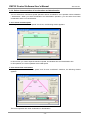
3-14-1. Select constant speed
When you check the "Constant speed" check box, the following window appears.
In this window, you cannot input the maximum speed, acceleration time and deceleration time.
In this operation, the motor operates at the initial speed.
3-14-2. Select linear acceleration
When you uncheck the "Constant speed" and "S-curve accel/decel" checkbox, the following window
appears.
The motor operates with linear acceleration or deceleration.
- 14 -
FMC32 Control Software User's Manual
YA7175-0/0
3-14-3. Select S-curve acceleration
When you uncheck the "Constant speed" checkbox and check the "S-curve accel/decel" checkbox, the
following window appears.
The motor operates with S-curve acceleration/deceleration.
3-15. Adjustment of magnification
To actualize the operation speed specified in the maximum speed or the initial speed, the maximum rate
will be calculated automatically and a magnification rate that is more than 1 is used normally.
If you want to use the magnification rate that is less than 1, please check the "Magnification of one or
less is permitted" checkbox. However, even if you check this checkbox, the magnification rate does not
become less than 1 if the calculated magnification rate should be more than one.
- 15 -
FMC32 Control Software User's Manual
YA7175-0/0
3-16. Switch the operation direction
Click the following button to switch the operation direction (CW or CCW).
The display of the button shows the current operation direction.
CW
direction
CCW
direction
3-17. Switch excitation
Click the following button to switch the excitation condition.
The display of the button shows the excitation condition.
Excitation off
Excitation on
3-18. Start operation
Click the "execute" button to start a specified operation.
The value shown in the "Register setting value" field is written in each register of PCD2112 and then the
command to start operation shown in the "COMMAND" column is written to PCD2112, and operation
starts. ("Command" cannot be changed to an arbitrary start command.")
At that time, if the excitation of FMC32 is off, it is switched to ON forcibly. It is not returned to OFF
automatically after operation is complete. However, if you click the "Stop" button to stop the motor
forcibly, the excitation condition returns to OFF. (In the case that the excitation is ON from the start, it
does not turn to OFF.)
3-19. Stop operation
While operating, you can stop the motor by clicking the "Stop" button.
- 16 -
FMC32 Control Software User's Manual
YA7175-0/0
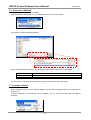
3-20. Register and confirm operation pattern
Up to 32 Operations (Operation patterns) designed in this window can be registered in one project. This
number of operations is the same as the number of operation patterns controlled by an external
EEPROM.
Please refer to PCD2112 User's Manual in detail.
3-20-1. Register operation
Up to 32 operation patterns created can be registered. At the registration, specify operation pattern
number (0 to 31). To specify the number, use the "Pattern Number" buttons. By clicking the "up" or
"down" buttons, you can change the number.
The background of number that the operation pattern
is not registered is grey
The background of number that the operation pattern
is registered is pink.
After selecting the number, click the "Register this data" button.
The next window appears. If there is no problem, click the "Set" button.
If you want to change the number that you want to register, select "Mode" or "Direction in the line
number you want and click the "Set" button to be confirmed. (It can also be confirmed by double-click).
Select a number you want to register and click the column of the number.
Comment
If you select the number that operation pattern is already registered, the data is overwritten and the data
registered before is deleted. (Confirmation message does not appear).
In the comment field, the character strings that are input in the "Comment" field in the lower of the
"Design the data of pattern" window. If no comment is input, a comment input window appears after you
clicking the "Set" button.
3-20-2. Confirmation operation 1
If you click the "up" or "down" button to change a pattern number, the value registered with the number
is reflected on the "Design the data of pattern " window.
If you select a number from the pull-down menu, it produces the same result..
- 17 -
FMC32 Control Software User's Manual
YA7175-0/0
3-20-3. Confirmation operation 2
If you click the "select" button, the following window appears and you can check the registration of
operation pattern.
In this window, all registered operation patterns are not shown, we recommend you to input a brief
comment to describe each pattern number.
To input and modify a comment in this window, double-click the modified comment box. In the window
shown newly, you can input and modify them.
When you click the "set" button, the modified comments are reflected in the window.
- 18 -
FMC32 Control Software User's Manual
YA7175-0/0
3-21. Save the registered pattern data
Save the registered data to a project as an operation pattern.
To save operation pattern, select "Save Pattern data" from the "File" menu.
3-22. Import pattern data
You can load the operation pattern created in the past.
Select "Import pattern data" from the "File" menu. On the next window, select the file that you want to
load.
After you load the operation pattern, please save it.
- 19 -
FMC32 Control Software User's Manual
YA7175-0/0
3-23. Environment setting
You can set and change the environment of FMC32.
Select "Environmental setting" from the "Setting" menu.
The following function setting window are shown
(By selecting the "setting" tabs, the following two windows can be selected.)
Selecting any of the checkboxes alters the environmental parameters. These values are only applied
after clicking the "Set" button in the bottom right of the window.
If you want to make the setting valid at the next program start, click the "Set as Default" button.
- 20 -
FMC32 Control Software User's Manual
YA7175-0/0
3-23-1. Select output pulse details
The FMC32 has a driver for stepper motors. However, there may be cases when you want to use other
driver. In this case, the direction signals and driver command pulses output from FMC32 can be used.
Turn Switch 3 ON. Otherwise this selected setting is ignored and excitation sequence is output as
pulses to drive a motor.
Selection item
(+) direction
(-) direction
Pulse specifications
OUT: Drive pulse (negative logic)
DIR: Direction signal (High: + direction)
OUT: Drive pulse (positive logic)
DIR: Direction signal (High: + direction)
OUT: Drive pulse (negative logic)
DIR: Direction signal (Low: + direction)
OUT: Drive pulse (positive logic)
DIR: Direction signal(Low: + direction)
OUT: CW pulse (negative logic)
DIR:CCW pulse (negative logic)
90-degree phase deference
CW: OUT is ahead
90-degree phase difference
CCW: OUT is ahead
OUT: CW pulse (positive logic)
DIR: CCW pulse (positive logic)
3-23-2. The SD input is effective
If you check this checkbox, the slow-down signal input is enable. Without check, the slow-down signal is
ignored.
3-23-3. Select the process , when the SD input is turned
You can select one from the following operations when the SD signal is input.
1. Decelerate to the initial speed. (Does not stop.)
2. Decelerate to the initial speed and stop.
However, there are the following limits.
1) "The SD input is effective" checkbox is checked.
If it is not checked, the SD input is ignored.
2) When the motor is operating at constant speed, it does not decelerate.
3-23-4. Set the latch function of the SD input
If you check this checkbox, the condition when the slow down signal turns ON is memorized. According
to this, the motor ensures to slow down even though the width of slow-down signal is narrow.
The memorized slow-down signal will be cleared at the start of next operation.
3-23-5. Select SD signal input logic
Select a signal level to be recognized that slowdown signal is ON. When "Positive logic" is selected with
FMC32, turning input photocoupler ON makes the SD input ON.
- 21 -
FMC32 Control Software User's Manual
YA7175-0/0
3-23-6. Select the process , when the PEL/MEL input is turned
You can select one of the following operations when the end limit signal is input.
1. Stop immediately.
2. Decelerate and stop.
Input logic of the end limit signal is specified using switch 5 (SW1-5) of the dip switch.
3-23-7. Select ORG signal input logic)
Select signal level to be recognized that ORG signals is ON.
3-23-8. Set the noise filter to PEL,MEL,SD,ORG
If you check this checkbox, filters are set to End limit signal (both plus and minus), slow-down signal,
origin signal. According to filters, a pulse whose width is less than four micro sec is ignored.
3-23-9. The excitation sequence is turned off
If you check this checkbox, output of excitation sequence is turned off.
3-23-10. The excitation sequence is turned off according to the CDW timing
If you check this checkbox, output of excitation sequence is turned off while current down signal is
output.
3-23-11. Set the idling pulse counts
Before starting acceleration, you can select a number of pulse counts to operate at the initial speed
3-23-12. The mask of the pulse output
The pulse output is masked. The output of excitation sequence is not changed.
3-23-13. Completion of origin return resets counter
If you check this checkbox, the current position counter (RCUN) is reset to 0 when origin return is
complete. When the motor decelerates and stops, the counter counts pulse number to be output until
the motor stops.
3-23-14. When beginning to decelerate, INT is output
If you check this checkbox, interrupt occurs when deceleration starts and the INT output of PCD 2112
becomes low.
3-23-15. The positioning counter is stopped
If you check this checkbox, the positioning counter (RDWC) does not operate.
- 22 -
FMC32 Control Software User's Manual
YA7175-0/0
3-24. STA input in PC control mode
If the FMC32 is used in standalone mode, the operation pattern specified by the execution sequence
program starts when external input terminal STA is high (when the photocoupler is ON).
On the other hand, when the FMC32 is used in PC control mode, the STA input is ignored and operation
starts. PC control mode is often used to confirm operation as you like and write operation data to FMC
32.
If you want to use signals from the STA terminal while you confirm operation, click the "Auto" button and
turn off the auto start mode.
Display
Function
The STA input is ignored and operation starts.
Operation starts when STA input is turned on.
However, operation does not starts until STA input become Low to High (the photocoupler becomes
OFF to ON). When STA input is high at the start of operation, STA input should become low once and
then become high again. This is the specification of this product.
Please note that mechanism of operation start in standalone mode is different from one in PC control
mode. (In the PC control mode with automatic start mode off, operation by command 1 (Pn) with a
specified operation number is the same as operation by Command 2 (Sn) with the specified operation
number.)
- 23 -
FMC32 Control Software User's Manual
YA7175-0/0
4. Design the data of pattern Window
This shows how to design FMC32 execution sequence program.
It is designed by arranging several operation patterns designed in the "Design the data of pattern"
window. In the standalone mode, operation patterns are executed in order they are assigned.
Execution sequence program is simply called "program" here.
Select "Design the program" from the "Tool" menu in the main window.
The following editor window (simple text editor) appears. Input program using keys directly.
Comment that shows a program file is described by default.
Do not delete or change "#FMC32#" on the first line.
- 24 -
FMC32 Control Software User's Manual
YA7175-0/0
4-1. FMC32 command
In programming here, FMC32 specific program commands are used to design execution sequence
program. Up to 255 bytes can be used for command and data.
4-1-1. Command__1to specify an operation number
Operate the specified numbered operation pattern.
The start of operation is when STA input become high. When STA input is low (photocoupler is off), the
motor waits for STA input and starts after the STA input becomes high.
After operation is complete, the next command is processed immediately.
Specify the operation pattern number that is already created and follow the number after "P".
Example
P0
Operation description
Operation pattern 0 is executed.
4-1-2. Command_2 to specify an operation number.
Operate the specified numbered operation pattern.
Operation starts when STA input become high. When STA input is low, the motor waits for STA input and
starts after the STA input becomes high.
After operation is complete, the motor waits until the STA input to becomes low. Operation shifts to the
next command after STA input becomes low. When STA input is already low at the completion of
operation, the next command is operated immediately.
Specify the operation pattern number that is already created and follow the number after "S".
Example
S15
Operation description
Operation pattern 15 is executed.
4-1-3. Wait for specified time
The unit of waiting time is msec. Specify a numerical value with one or more spaces following "WAIT".
The motor waits for 10 times the input value and operation shifts to the next command after waiting.
The range of value is 0 to 255. Specify values in decimal or hexadecimal.
Example
WAIT 10
WAIT 0x20
Operation description
Wait for 100 msec. (Example in decimal)
Wait for 320 msec. (Example in hexadecimal)
4-1-4. Excitation OFF
Excitation of the stepping motor driver that is mounted on the FMC32 is turned OFF.
Example
EX_OFF
Operation description
Excitation OFF
- 25 -
FMC32 Control Software User's Manual
YA7175-0/0
4-1-5. Excitation ON
Excitation of the stepping motor driver that is mounted on the FMC32 is turned ON.
Example
EX_ON
Operation description
Excitation ON
Note : When excitation ON command (EX_ON) is processed in program, Excitation OFF by external
input (MON) (Photocoupler OFF) cannot be process on the program. (Priority to commands).
4-1-6. Setting value to variable
The FMC 32 has variables that are distinguished by the number 0 to 15.
Any number from 0 to 255 can be set to these 16 variables.
To specify values, select the variable number following "REG". and add more than one characters space
and a value you want to set.
Example
REG1 10
Operation description
Set 10 to REG1.
4-1-7. Decrement variable value
Decrement 1 from the specified variable value.
Specify a variable number and follow after "DEC".
Example
DEC2
Operation description
Decrement the REG2 value.
4-1-8. Set label
You can set a label at any place in program.
The label is used as a jump address of jump command.
To specify labels, describe any character strings (alphanumeric characters and underscore) following ":"
(colon).
Alphabetical capital letters and small ones are discriminated.
Up to 256 label can be set.
Labels are not commands to operate.
Example
:LOOP_A
Operation description
Label name is LOOP_A.
4-1-9. Conditional jump
When referred variable value is other than 0, the program process jumps to a specified label.
When referred variable value is 0, the program process shifts to the next line command.
Describe a referred variable number following "JNZ", add more than one characters space and specify a
label.
Example
Operation description
JNZ REG3 LOOP_A
When REG3 variable is other than 0, jump to LOOP_A
label.
- 26 -
FMC32 Control Software User's Manual
YA7175-0/0
4-1-10. Unconditional jump
Jump to a specified label.
Specify a label following after "JMP" and more than one character space.
Example
JMP LOOP_B
Operation description
Jump to LOOP_B.
4-1-11. INT Jump
Jump to the specified label while PCD2112 generates an interrupt cause.
When an interrupt cause does not occur, the process shifts to the next line command.
The interrupt is cleared only after an INT jump is executed.
Specify label following after "JP1" and more than one character space.
Example
JPI LABEL
Operation description
When an interrupt cause occurs, jump to the specified label.
4-1-12. Stop
This command stops program execution.
Even if other commands are written after this command, the program does not shift to the next process.
Example
HALT
Operation description
This command stops FMC32's operation.
4-1-13. Comment
When you describe "#" (one-byte crosshatch), the character strings from # to line feed character is
treated as comments.
If you insert # at the head of the line, the whole line is treated as comments.
If you makes the last part as commands, separate command from "#" with more than one character
space.
#Comment line
REG0 20 #“20” is substituted to Register 0
- 27 -
FMC32 Control Software User's Manual
YA7175-0/0
4-1-14. Command specification
Abbreviatio
n
Pn
Sn
WAIT
EX_OFF
EX_ON
REGn
DECn
NJZn
JMP
JPI
HALT
Command name
Command_1 to specify
operation number
Command_2 to specify
operation number
Wait for specified time
Excitation OFF
Excitation ON
Set value to variables
Variable value-1
Conditional jump
Unconditional jump
INT jump
Stop
Bit train
Command byte
length
7
6
5
4
3
2
1
0
1
0
0
0
n
n
n
n
n
1
0
0
1
n
n
n
n
n
2
1
1
2
1
2
2
2
1
0
1
0
0
0
0
0
0
0
1
0
1
0
0
1
0
0
1
0
1
0
0
1
1
0
1
1
0
n
n
n
n
0
1
1
1
n
n
n
n
1
0
0
0
n
n
n
n
1
0
0
1
0
0
0
0
1
0
0
1
0
0
0
1
1
1
1
1
1
1
1
1
Caution:
When the FMC32 is used in PC control mode, there are the following limits on operation.
(Please bear in mind that controlling FMC32 by this software does not extend beyond confirmation of
the execution sequence program. )
1) Using "PN" or "SN", the motor ignores the STA input and operates.
(You can cancel to ignore the STA input. In details, see 4-7-5. STA input in PC control mode.)
2) Because FMC32 control software is controlled by windows, it takes some times to process the next
command after one command is processed. (The length of this time depends on the PC's
performance.)
- 28 -
FMC32 Control Software User's Manual
YA7175-0/0
4-2. Command input to editor
The FMC32 has a feature to support command input.
Click the line that you want to input commands to move a cursor and click the following button.
Or, right-click the line that you want to input commands on the editor window.
The following pop-up menu appears. Select a command you want to use from the menu.
4-2-1. Select operation pattern
Select "Select the pattern number" from the pop-up menu. The following selection window appears.
Selecting an operation pattern you want to use adds the operation pattern in the line with cursor on the
editor as follows. (Comments are also described at once.)
- 29 -
FMC32 Control Software User's Manual
YA7175-0/0
Check the "STA_edge" checkbox to specify a command waiting for falling of STA input.
The following button allows to operate the same.
4-2-2. Input a command for the specified time
If you click "WAIT time setting" and "Set time" from the pop-up menu, the following input window
appears.
Remember that the input time is multiplied by 10 when actually executed. (i.e. and entry of 10 yields a
WAIT time of 100ms.)
4-2-3. Select Change excitation
Click "Change excitation" and "Excitation ON or "Excitation OFF" from the pop-up menu, the specified
setting command is described to the setting editor.
- 30 -
FMC32 Control Software User's Manual
YA7175-0/0
4-2-4. Select a value setting command to variables
Click "Set the variable register" and "Register number 0 to 15" of the pop-up menu. The following entry
window appears.
If you Input a value that you want to set to a variable in decimal, a REGx command is described in the
editor.
4-2-5. Select a decrement the variable register
Click to "Decrement the variable register" and "Register number 0 to 15" from the pop-up menu. The
setting command specified is described in the editor.
- 31 -
FMC32 Control Software User's Manual
YA7175-0/0
4-2-6. Selection of jump processing
Click "Selection the Jump processing", "Jumps if the register value is not zero" and "Register number 0
to 15" from the pop-up menu. The following entry window appears.
If you input the jump address label (Line head colon ":" should be omitted.), conditional jump command
is described in the editor.
- 32 -
FMC32 Control Software User's Manual
YA7175-0/0
4-2-7. Input commands of unconditional jump and INT jump
Click "Selection the Jump processing", "Unconditional jump" or "Jumps if the interrupt is generated". The
following entry window appears.
If you input the jump address label (Line head colon ":" should be omitted.), conditional jump command
is described in the editor.
- 33 -
FMC32 Control Software User's Manual
YA7175-0/0
4-2-8. Label
Click "Label" from the pop-up menu. The following entry window appears.
When you input the jump address label (Line head Colon should be omitted), the label is described in
the editor.
Up to 256 labels can be used in one project.
4-3. Save a program
Save a designed program before you assemble it.
Select "Save Program" from the "File" menu or click the following button to save a program to a project.
4-4. Import a program
You can load and reuse the program designed in the past.
Select "Import Program" from the "File" menu or click the following button. The window to select a file
appears. Select a program file and load it.
After you import a program, do not forget to save it.
- 34 -
FMC32 Control Software User's Manual
YA7175-0/0
4-5. Check description content and assemble
4-5-1. Assemble and check description content
Select "Assemble" from the "Project" menu or click the following button.
The designed program is checked to see if it meets the FMC command system grammar rules. If the
program is grammatically correct, it is assembled.
If there is no violation of the grammar rules (i.e. errors), the described line is highlighted in yellow and
the first line of the program is displayed inverted as follows. Any lines with comments and label are not
highlighted.
There is an error, the following message appears.
- 35 -
FMC32 Control Software User's Manual
YA7175-0/0
Click the "Close" button to exit the error message. The lines with error points are highlighted. (To click
the editor window deletes the highlight.)
In this example, "P99" becomes an error because operation pattern can only be specified from "P0" to
"P31".
Caution: Save a designed program before you assemble. If there are no errors caused by assembling it,
".sdc" file can be generated. This file is used when it is written to EEPROM.
4-6. Run( Simulation)
4-6-1. Step execution(Simulation)
If there is no violation of the grammar rules and the operation description is checked normally, you can
simulate the program.
Click "Step Execution" from the “Project” menu or the following "Step Execution" button. The highlighted
first command line is processed and the next command line will be highlighted.
[Step Execution button]
By repeating "Step Execution", confirm that the program is processed in the order that you want. It is
especially important to confirm that jump commands are processed in the order as you intended.
- 36 -
FMC32 Control Software User's Manual
YA7175-0/0
4-6-2. Continuous execution(Simulation)
Click "Execution" of the "Project" menu or the following "Continuous Execution" button. The highlighted
line moves as execution sequence program. It shifts at the speed that you can follow with your eyes.
[Continuous execution button]
4-6-3. Simulation of interrupt
Click the following "Variable value display button" and "INT on". Pseudo interrupt occurs.
[Variable value display button]
Here
4-6-4. Break function
During continuous execution, you can interrupt continuous execution at any line you want.
Click the line where you want to interrupt continuous execution. Next, right-click to show the pop-up
menu. If you select "Break ON/Off" from the pop-up menu, the line is highlighted as follows.
Here
To cancel a break, click the line and right-click and do the same operation. If the line is highlighted in
yellow, the break function is canceled.
You cannot set a break in anything other than command lines. You cannot set a break in label line. (A
label is not a command to be executed.)
- 37 -
FMC32 Control Software User's Manual
YA7175-0/0
4-7. Execution( Real operation)
4-7-1. Step execution(Simulation)
After you confirm that the program is processed in the order you want to, you can confirm that the motor
actually operates.
At first, turn external input signal "MON" of this product ON (photocoupler ON) or click the following
button to set excitation to ON. (When an EX_ON command is used, you do not have to follow the
procedure to turn excitation ON.
Excitation off
Excitation on
Then, select "Selection of simulation operation" and "Real simulation" from the "Tool" menu.
By doing this, the mode becomes the actual operation mode.
Switching to real operation mode can be done by the following button.
The condition of this button allows you to confirm whether or not the real operation mode.
Real operation mode
- 38 -
FMC32 Control Software User's Manual
YA7175-0/0
Then, click the "STEP execution" button. The highlighted first command line is processed and the next
command line will be highlighted.
[STEP execution button ]
When you press the "STEP execution" button in this
state, the command in this line is processed.
After a command is processed, the
next command line will be highlighted.
4-7-2. Continuous execution(Real operation)
Click "Execution" of the "Project" menu or the following "Continuous Execution" button. The highlighted
line moves as execution sequence program. It shifts at a speed that you can follow with your eyes.
[Continuous execution button ]
4-7-3. Temporary stop of continuous execution
You can stop continuous execution by clicking the following button.
When the motor is operating in real operation, it stops after command operation is complete. If an
operation pattern that takes some time until the motor stops is processing, please wait until the
operation is complete.
If you click the "Step execution button" or "Continuous execution button", the FMC32 starts to process
the next command to the processed command.
If you want to restart the program from the beginning, click the "Assemble" button.
- 39 -
FMC32 Control Software User's Manual
YA7175-0/0
4-7-4. Forcible stop of continuous execution
Click the following button to stop operation forcibly at the moment you click. You can use this button only
in real operation mode.
If you click the "STEP execution button" or "Continuous execution button" after a forcible stop, FMC32
restarts to process the next command to the processed command. However, the operation may not be
as you want to because the stepper motor may not perform predictably during a forcible stop.
If you want to restart the program from the beginning, click the "Assemble" button.
4-7-5. STA input in PC control mode
If the FMC32 is used in standalone mode, the programmed operation pattern starts when external input
terminal STA turns High.
On the other hand, when the FMC32 is used in PC control mode, operation starts and ignores STA
input.
The purpose of using the PC control mode is assumed to be for confirmation that the created
programmed operates as you like and to write operation data to the FMC 32.
If you want to use signals from the STA terminal while you are confirming operation, click the "Auto"
button and turn off the auto start mode.
Display
Function
Operation starts and ignores an STA input.
Operation starts when an STA input is turned on.
However, operation does not start until the STA input becomes from Low to High. When the STA input is
high at the start of operation, STA input should become low once and then become high to start
operation. This is the specification of this product.
Please note that mechanism of operation start in standalone mode is different from the one in PC
control mode. (In the PC control mode with automatic start mode off, operation by command_1 (Pn) to
specify an operation number is the same with operation by Command_2 (Sn) to specify an operation
number.)
- 40 -
FMC32 Control Software User's Manual
YA7175-0/0
5. Inching operation
Click "Inching Operation" from the "Tool" menu on the menu bar.
The following window appears.
Operation speed
Operation selection
Feeding amount
Next to "Position", the value of feeding amount in inching operation appears. The value is cleared by
clicking the "Position clear" button.
5-1. Continuous operation
Select "Continuous operation" from the pull-down menu.
Next, input an operation speed in the "Passing speed" field.
Then, select operation direction. By clicking the "+" button, the display is switched to "-". Click the "start"
button to start operation at the speed input ahead.
This operation continues until the "stop" button is clicked.
5-2. Positioning operation
Select "In positioning operation" from the pull-down menu. Next, input the operation speed in the
"Passing speed" field and input feeding amount (the total number of pulses). Then, select operation
direction. By clicking the "+" button, the display is switched to "-". Click the "start" button. The number of
pulses input in the "Feeding amount" field is output at the speed input ahead. This operation stops
automatically without clicking the "stop" button.
- 41 -
FMC32 Control Software User's Manual
YA7175-0/0
6. Access to Serial EEPROM
The FMC32 operates in standalone mode by writing designed operation patterns and execution
subsequence program using operation patterns (program ) to EEPROM on the FMC32.
6-1. Write to EEPROM
Write the designed operation pattern and the program using the operation pattern to EEPROM on
FMC32.
Click "Write to EEPROM" from the EEPROM menu on the Main window.
While operation pattern is being written, the following message appears.
Operation patterns are not written to the operation numbers that an operation pattern is not registered.
Comments are also not written.
If writing operation patter is completed normally, writing program starts.
All writing is completed, the following message appears.
Caution: To Write created program, assemble it before writing program.
Check whether the program has any errors by assembling it.
If you write an unassembled program, the following error message appears and the program is
not written. (Operation pattern is written.)
Unsaved programs are not written. Please save it ahead of time.
Message example
Please assemble the program.
The program has been changed. Please assemble it.
Please save the program.
Please save the data of pattern.
- 42 -
FMC32 Control Software User's Manual
YA7175-0/0
6-2. Read data in EEPROM
Read data written in EEPROM on FMC32.
Click "Read data in EEPROM" from the "EEPROM" menu on the main window.
The window to select saved files appears.
Input a file name without extension. The following two files with this file name are generated.
Generated files
.edt
.sdc
Content
Operation pattern data read
Read program data after assembling.
You can use an ".edt" file in other projects by importing. (Comments cannot be used.)
7. Language selection
Select "language select" from the "Others" display. You can select language used such as Japanese or
English, etc.
To select Japanese, The characters may be garbled if you do use an OS that does not supports
Japanese.
- 43 -
FMC32 Control Software User's Manual
YA7175-0/0
8. Adjustment mode
You can use the adjustment mode to adjust current to stepping motors. It allows to forcibly cancel
current down function that is always available.
It also allows you to change all items that you cannot select on RENV1, RENV2, RMD and each register
setting windows.
Open a project by selecting "New project" or "Load project", etc and open "design the data of pattern"
window.
Select "Adjustment mode" from the "Setting" menu in this window.
The current down switching button appears in the window.
At the same time, the following inching operation window appears. In this window, the current down
switch button is added.
- 44 -
FMC32 Control Software User's Manual
YA7175-0/0
By click the current down switching button, you can switch condition of current down signals.
Condition of
Current down
Note
button
Valid
Normally, current down is controlled automatically. During
stopping, current down is always valid.
Invalid
During stopping, you can make current down feature
invalid. After operation start, it returns to invalid
automatically at the operation stop.
In adjustment mode, you do not use the following features.
1. You cannot register operation patterns.
2. You cannot change environmental settings.
If you click the "execute" button with current down invalid, current down feature returns to valid forcibly.
To quit adjustment mode, select "Adjustment mode" from the "Setting" menu again. If you quit
adjustment mode with current down invalid, it returns to valid automatically.
- 45 -
FMC32 Control Software User's Manual
YA7175-0/0
9. Control PCD2112 directly
This software can control PCD2112 mounted on FMC32 directly.
Using this method, you can write value to the registers of PCD2112 directly, but the data etc. does not
have any influence on designing operation patterns. (Register values set here are discarded at the time
to create operation pattern.)
This function is designed to understand PCD2112 functions.
9-1. Function description of the main window
Each function description follows illustration of the main window again.
Register name Register value
Register value display
Address entry
Data entry
Data check area
Write register button
Detail setting button.
[Main window]
9-1-1. Register value entry
PCD2112 has 20 kinds of registers.
PCD2112 reads these registers each specified cycle through USB and shows the values.
In this window, you can check the condition that FMC32 is operating.
9-1-1-1. Set value to register
If you double-click each register, write address of the register appears in the address entry field by
double-click and the cursor moves the "data entry" field.
If you input data in the "data entry" field and click "write" button, data is written in the register specified.
Written data is read immediately and is reflected on the window.
9-1-1-2. Select radix of register value
If "h" is attached to the last of register value shown, the value is displayed in hexadecimal notation.
When you right-click this value, radix of register shown is switched from decimal to hexadecimal.
- 46 -
FMC32 Control Software User's Manual
YA7175-0/0
9-1-2. Address display
It shows the head address of the register that data is written to. You cannot input in this field using the
keyboard.
9-1-3. Data entry field, Data confirmation field
According the types of registers, length of data to be written varies.
When you double-click register display to generate address automatically, the necessary number of data
bytes is also automatically determined and FMC32 makes you input the number of bytes.
The radix of data input is the same as the radix of the register value.
Example of
4 byte write
(RENV2 register)
Example of
3 byte write
(RDP register)
Example of
2 byte write
(RMG register)
Example of 1 byte
write
(RCOM register)
If the radix is hexadecimal ("h"), you cannot input data more than the necessary bytes. Using decimal,
you can input data more than the necessary bytes. However, the parts of other than the necessary bytes
are deleted.
The content of "data confirmation" field is as follows.
Radix
Offset values.
The head is address
input in the "address
entry" field.
Decimal
Hexadecimal
You can confirm to which
part of specified address
the data input in the data
entry field is written.
In decimal, data is input in the data entry field in decimal, but is shown in hexadecimal notation in
the data confirmation field.
- 47 -
FMC32 Control Software User's Manual
YA7175-0/0
9-1-4. Register write button
Data input in the data entry field is written to address input in the address entry.
9-1-5. Detail setting button
Each register of "RENV1", "RENV2", "RMG", "RMD, "RCOM" and "RIOP" has its meaning by bit.
User's manual describes these registers in details. To save the need of seeing user's manual, you can
use the "detail" button when you create data of these registers.
If you click this button, the detail setting window of each register appears.
9-2. Advanced setting of registers
In each register of "RENV1","RENV2", "RMG", "RMD", "RCOM", and "RIOP", there is a detailed setting
window.
If you click the "Detail" button, the window to support data design appears.
The setting window of each register is described as follows.
9-2-1. Advanced setting of RENV1 register
Double click the register value display of environmental setting 1 register (RENV1) and click the "detail"
button to show the following window.
This window is composed of the pull-down menu and checkboxes. If you select each item of
environmental setting 1 register and check the checkbox, the corresponding bit structure can be
automatically generated. (The items that you cannot select cannot be changed because the FMC32
does not use them.)
After setting, click the "set" button to set automatically generated data in the data entry field of the main
window and write in a register at the same time.
If you click the "Cancel" button, the automatically generated data is input in the data entry field of the
main window, but data setting to the register is not made. Click the "Write" button in the main window
to write this data to a register.
- 48 -
FMC32 Control Software User's Manual
YA7175-0/0
9-2-2. Advanced setting of RENV2
Double click the register value display of environmental setting 2 register (RENV2) and click the "detail"
button to show the following window.
This window is composed of the pull-down menu and checkboxes. If you select each item of
environmenta2 setting 1 register and check the checkbox, the corresponding bit structure can be
automatically generated. (The items that you cannot select cannot be changed because the FMC32
does not use them.)
After setting, click the "set" button to set automatically generated data in the data entry field of the main
window and write in a register at the same time.
If you click the "Cancel" button, the automatically generated data is input in the data entry field of the
main window, but data setting to register is not made. Click the "Write" button in the main window to
write this data to a register.
- 49 -
FMC32 Control Software User's Manual
YA7175-0/0
9-2-3. Advanced setting of RMG register
If you double-click "multiplication" field of setting register (RMG) and click the "Detail" button". The
following window appears.
Setting reference clock
Setting multiplication
Value to be set to RMG register
Actual multiplication used when set value to
RMG register is applied.
For setting reference clock, set the clock frequency that will be provided to the PCD2112.
The value for FMC32 is 9.8304MHz.
After setting, click the "set" button to set the automatically generated data in the data entry field of the
main window and write it to the register at the same time.
If you click the "Cancel" button, the automatically generated data is input in the data entry field of the
main window, but data setting to register is not made. Click the "Write" button in the main window to
write this data to a register.
9-2-4. Advanced setting of RMD register
If you double-click "Operation mode select" setting register (RMD) field and click the "Detail" button".
The following window appears. (If you open the RMD setting window using the window to design the
data of pattern, the "Set as Default" button is added.
This window is composed of the pull-down menu and checkboxes. If you select each item of operation
setting register or check the checkbox, the corresponding bit structure can be automatically generated.
(The items that you cannot select cannot be changed because FMC32 does not use them.)
After setting, click the "set" button to set automatically generated data in the data entry field of the main
window and write it in a register at the same time.
If you click the "Cancel" button, the automatically generated data is input in the data entry field of the
- 50 -
FMC32 Control Software User's Manual
YA7175-0/0
main window, but data setting to register is not made. Click the "Write" button in the main window to
write this data to a register.
9-2-5. Advanced setting of RCOM register
If you double-click "Command register (RCOM) field and click the "Detail" button", the following window
appears.
This window shows buttons of all operation directives to be specified to the PCD2112. If you click each
button, the corresponding directive is processed.
- 51 -
FMC32 Control Software User's Manual
YA7175-0/0
9-2-6. Advanced setting of RPIO register
If you double-click "General-purpose port register (RPIO) field and click the "Detail" button", the
following window appears.
This window is composed of the pull-down menu and setting data to operate each general-purpose port
can be automatically generated.
After setting, click the "set" button to set automatically generated data in the data entry field of the main
window and written in a register at the same time.
If you click the "Cancel" button, the automatically generated data is input in the data entry field of the
main window, but data setting to register does not be made. Click the "Write" button to write this data
to a register.
9-3. Select operation directive to FMC32
Select "Selection of instruction to FMC32" from the "Tool" menu. The following window appears.
This window shows buttons of all operation directives to be specified to the PCD2112. If you click each
button, the corresponding directive is processed.
- 52 -
FMC32 Control Software User's Manual
YA7175-0/0
9-4. Confirm the detail of registers
The register "RSTS", "RIST" and "RIOP" has each meanings by bit.
Regarding RSTS and RIST, the window to refer the information by bit is prepared.
9-4-1. Confirm the detail of RSTS register
Select "RSTS window" from the "Tool" menu, the following windows appears.
Here, the bit information of status information register (RSTS) appears visually.
The bit of RSTS register that has meaning by bit, when the corresponding bits are "1" or "0", the bit
status changes as follows.
Bit status
0
1
When the multiple bits have one meaning, the numeral value that the multiple bits shows will be shown
by characters.
- 53 -
FMC32 Control Software User's Manual
YA7175-0/0
9-4-2. Confirm the detail of RIST register
Select RIST window from the "Tool" menu. The following windows will be shown.
The bit information of the RIST register appears visually.
You can confirm the condition of each bits of the RIST register. The style of the display is the same as
one of the RSTS register.
- 54 -
FMC32 Control Software User's Manual
YA7175-0/0
10. Meaning of messages and solution
While using the software, message may appears when trouble occurs. The followings show causes and
countermeasures of each message.
Code
Message
Failure of EEPROM
access mode
M0001
Not ready for
EEPROM
access(1)
M0002
M0003
Not ready for
EEPROM
access(2)
Not ready for
EEPROM
access(3)
M0004
M0005
Not ready for
EEPROM
access(4)
RMV becomes less
than three
M0006
M0007
RFH register value
cannot be set
RFL register value
cannot be set
M0008
Cause / Countermeasure
Though FMC32 issues a transition command to "EEPROM access
mode" to PCD2112 (See 5-1. Bus control command of PCD2112 User's
Manual) and check a connected serial EEPROM, this serial EEPROM
is not ready. Therefore, data is not written to the serial EEPROM.
Wiring to serial EEPROM may be disconnected.
Serial EEPROM may be broken.
The device may need to be repaired.
Though FMC32 issues a transition command to "EEPROM access
mode" to PCD2112 (See 5-1. Bus control command of PCD2112 User's
Manual) and issues "Write enable" command to a connected serial
EEPROM, this serial EEPROM is not ready for this command.
Therefore, data is not written to the serial EEPROM.
Wiring to serial EEPROM may be disconnected.
Serial EEPROM may be broken.
The device may need to be repaired.
After writing data of 32 bytes to connected serial EEPROM, serial
EEPROM does not become ready.
It is unclear Whether or not data is written to the serial EEPROM.
Wiring to serial EEPROM may be disconnected.
Serial EEPROM may be broken.
The device may need to be repaired.
After writing data of 32 bytes to connected serial EEPROM and
sending "Write enable" command to serial EEPROM to write the next
data, the status does not become ready after receiving this command.
first 32 bytes of data is written to serial EEPROM, but the next data is
not written.
Serial EEPROM may be broken.
The device may need to be repaired.
After writing data of 32 bytes and 2 bytes continuously to a connected
serial EEPROM, the status does not become ready. It is unclear
whether or not the 2 bytes data (of second time writing) data is written
to serial EEPROM.
Serial EEPROM may be broken.
The device may need to be repaired.
RMV reaches to a lowest limit you can set as a magnification setting
register.
This means that pulse cycle setting value at the high speed exceeds
PCD2112 capacity.
Procedure is interrupted.
Step down the value of pulse cycle at high speed.
This means that pulse cycle setting value at the high speed exceeds
PCD2112 capacity.
Procedure is interrupted.
Step down the value of pulse cycle at high speed.
1. The value set for pulse cycle setting value at low speed exceeds the
capacity of PCD2112.
Procedure is interrupted.
Step down the value of pulse cycle at low speed.
2.Though magnification for pulse cycle setting at high speed is
automatically calculated, smaller than this magnification cannot be set
for pulse cycle at low speed.
Procedure is interrupted.
Step down the value of pulse cycle at low speed.
- 55 -
FMC32 Control Software User's Manual
Please larger RFH
than RFL
M0009
M0010
RMV register value
cannot be set
M0011
RUR register value
cannot be set
M0012
RDR register value
cannot be set
M0013
20MHz or more
cannot be set
RMV register is too
small
M0014
M0015
Please adjust RDR
and RUR to the
same value
M0016
Search of USB
device wait a
moment
USB device is not
found.
M0017
M0018
M0019
PCD2112 is not
found.
Set data is not
written in the
register
YA7175-0/0
Setting value for pulse cycle at high speed is smaller than one at low
speed.
Procedure is interrupted.
Make setting value for pulse cycle at high speed larger than one at low
speed.
(Actually, PCD2112 operates in spite of the setting like this.)
Feeding amount is too large.
Procedure is interrupted
Make feeding amount smaller.
Time for acceleration is too small or too large.
Procedure is interrupted.
Make this value appropriate.
Time for deceleration is too small or too large.
Procedure is interrupted.
Make this value appropriate.
Procedure is interrupted.
Do not change reference clock frequency basically.
However, PCD2112 can operate normally up to 20MHz.
Feeding amount set is too small compared to the number of pulses
generated during acceleration / deceleration.
There may be cases that the pulse cycle cannot be reached to the
setting value because of triangle drive or FH correction.
You can select to stop or continue operation.
In the case that slowdown point is set automatically, an acceleration
rate should be the same as a deceleration rate.
If manual setting is selected for slowdown point, this message can be
ignored.
You can select to stop or continue operation.
FMC32 is searching for PUSB3503 connected to PC.
Just after PUSB3503 is connected to PC, the PC's OS may take some
time to finish recognizing the USB device. In this case, this message
appears.
PUSB3503 is not connected to PC, or OS cannot recognize an USB
device.
Possible causes are as follows.
1.Device driver is not installed correctly.
- In windowsXP, you can check an USB device connection using
device manager. In the case that device driver is not installed
correctly, install device driver.
2.OS stays in recognizing.
- Select "Initial" from the "Tool" menu to operate or restart software.
3.PUSB3503 is not connected.
- Connect PUSB3503 or plug USB again.
Though PUSB3503 is connected, PCD 2112 is not connected or power
is switched off.
Because you exit the detail setting window using "Cancel", setting data
has not saved in register.
Click the "Write" button to save data.
When register data is written to serial EEPROM in standalone mode, 34 bytes of data will be written.
32 byte data is written to EEPROM at once process according to EEPROM's specification. Therefore,
data write is processed two times with separating 32 bytes write and 2 bytes write.
- 56 -