1
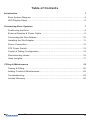
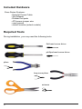
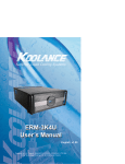
®
Superior Liquid Cooling Systems
Exos-2 LX, Exos-2.5
User’s Manual
English v1.2
Protected by U.S. Patents 6,313,990; 6,664,627; 7,167,366; 7,295,436
Other Technology Pending U.S. & World-Wide Patents
This User Manual is updated regularly. Please be sure to check our support page for a newer
version of this guide: www.koolance.com/support
GENERAL PRECAUTION
Please read this manual carefully before beginning the installation of your Koolance system.
This manual assumes the user has basic experience in building and configuring computer
systems. Information referring to traditional hardware assembly is intentionally brief.
ABOUT SIGNS
Throughout this document, critical information is highlighted in gray-colored boxes. The
following symbols are intended to help prevent any situation which may cause personal
injury and/or damage to equipment:
!
!
WARNING: Indicates a potentially hazardous situation which, if not avoided,
could result in personal injury or be life-threatening.
CAUTION: Indicates a potentially hazardous situation which, if not avoided,
may result in damage to equipment.
PROHIBITED: Indicates a prohibited action.
PROHIBITED USE
This product is designed, developed and manufactured as contemplated for general use,
including without limitation: general office use, personal use and household use, but is not
designed, developed and manufactured as contemplated for use accompanying fatal risks or
dangers that, unless extremely high safety is secured, could lead directly to death, personal
injury, severe physical damage or other loss, including without limitation: nuclear power core
control, airplane control, air traffic control, mass transport operation control, life support,
or weapon launching control. If these products are used in such hazardous environments,
Koolance Incorporated does not warrant them.
TRADEMARKS
The Koolance name and logo, and the Exos name and logo are trademarks or registered trademarks
of Koolance, Inc. Other company and product names used in this publication are for identification
purposes only and may be trademarks or registered trademarks of their respective companies.
COPYRIGHT
All rights reserved. Copyright (C) Koolance Incorporated
User Manual
i
!
!
!
WARNING: The Koolance liquid & coolant pack contain chemicals
which may be harmful or fatal if swallowed. KEEP THIS AND ALL
DANGEROUS CHEMICALS OUT OF THE REACH OF CHILDREN. If
ingestion has occurred, seek medical attention immediately. Give two
glasses of water. Do not induce vomiting. In the case of eye contact,
flush eyes immediately with water for 15 minutes. Remove contact
lenses. Call a physician if irritation persists. Some individuals may
have an allergic skin reaction with the solution, although generally mild.
Avoid contact as much as possible, and wash exposed area with soap
and water for at least 15 minutes. If irritation persists, or if contact has
been prolonged, get medical help. For further information, please visit
our website at: www.koolance.com
CAUTION: Koolance Incorporated can not be held responsible for any
damage to your system due to misconfiguration or incorrect installation.
If there is any point of installation that you do not understand, please
contact our Technical Support Staff at: [email protected], or visit
our website at: www.koolance.com/support
CAUTION: Liquid cooling systems are not yet universally supported by
hardware manufacturers. In some situations, adding liquid coolers and
other components to computer hardware might void the manufacturer’s
original warranty. Installation of the device is ultimately done at the user’s
own risk. If you have any specific questions on warranty coverage,
please contact your component or computer manufacturer.
KOOLANCE CONTACT INFORMATION
Koolance Incorporated (USA)
Address:
Telephone:
Fax:
Sales Email:
Tech Email:
ii
2840 W. Valley Hwy. N., Auburn, WA, USA 98001
+01-253-893-7551
+01-253-893-7573
[email protected]
[email protected]
Table of Contents
Introduction
1
Exos System Diagram .................................................................................... 4
LED Display Panel .......................................................................................... 5
Connecting Exos Systems
7
Positioning the Exos ....................................................................................... 8
External Nozzles & Power Cable .................................................................... 9
Connecting the Slot Adapter ......................................................................... 10
Installing the Slot Adapter ............................................................................. 11
Power Connection ......................................................................................... 12
ATX Power Switch......................................................................................... 13
Cooler & Tubing Configuration ...................................................................... 14
Disconnecting Hoses .................................................................................... 16
Hose Lengths ................................................................................................ 17
Filling & Maintenance
19
Testing & Filling ............................................................................................. 20
Adding Coolers & Maintenance .................................................................... 22
Troubleshooting ............................................................................................ 23
Limited Warranty ........................................................................................... 26
User Manual
iii
Included Hardware
Exos Series Systems:
- External Power Cable
- Slot Adapter
- Rubber foot pads
- ATX power jumper wire
- user manual
- shutoff nozzles (select models)
Required Tools
During installation, you may need the following tools:
flat-head screw driver
phillips-head screw driver
pliers
long-nose pliers
scissors
iv
1
Chapter
Introduction
User Manual
1
Congratulations on your purchase of a Koolance system!
As the most sophisticated product of its kind, Koolance offers many unique features found
nowhere else in the realm of computer cooling. In addition, you can expect to enjoy all of
the advantages that water-cooling technology brings with it.
Advantages of Water Cooling
Water transfers 30 times faster, and holds over 4 times more heat than air. With
this thermal conductivity and specific heat capacity, it’s easy to see why liquid cooling is
getting a lot of attention from hardware manufacturers.
Heat-producing devices in a typical computer are cooled by air. Generally, this involves
mounting a heat sink and fan to each component. For example, heat generated from your
CPU (or other heat source) is transferred into a metal heat sink, where a fan blows air
across its wide surface area.
While altering a heat sink’s size and makeup can improve the effectiveness, it is still
limited because air absorbs and transfers heat very slowly. To help compensate for this,
the fan is often run at a higher speed. Many people have therefore come to equate high
performance with high noise. As systems continued to be upgraded, the required heat
sinks simply got larger and louder.
Liquid cooling greatly reduces the noise issue. A larger amount of heat is withdrawn
from the components more quickly, and less airflow is required to cool them.
The heat exchanger is also located remotely from heat-producing devices, so airflow can
be controlled. This considerably reduces dust accumulation on sensitive hardware and
can result in a cleaner overall system.
Advantages of Koolance Systems
Koolance is the first company to offer fully-integrated, consumer-level PC liquid cooling
systems to the world-wide market. Our products are designed and built to look and
operate professionally. You will not need power tools or a tape measure to install your
Koolance system, and it should even be less difficult than assembling your own computer.
Koolance offers liquid coolers for every major hardware device. Providing enormous
flexibility, you can customize your system to fit your specific needs— cool dual processors
in a server, multiple hard drives in a RAID configuration, or add video cooling to a gaming
rig.
2
Introduction
The heart of a liquid cooling system is the pump. This device pushes liquid
through each cooler and into the heat exchanger. Koolance systems use dual
pumps to increase reliability and liquid pressure. If one pump should fail, the
second can help prevent potential damage caused by heat increase.
Every Koolance system includes built-in hardware safety features. Our
proprietary power control board constantly monitors liquid temperature, sounding
an alarm if it should get too high, and even turning off your computer if you are
not there to do so.
But Koolance’s innovations extend beyond just cooling features. Our safe,
patent-pending CPU Retention Clip places even pressure across the CPU,
protecting the chip and simplifying installation. There’s even a ratcheting tension
screw for precise contact pressure.
Finally, Koolance systems allow coolers to be easily exchanged and upgraded
to address future hardware compatibility.
User Manual
3
Exos System Diagram
Radiator Cooling Fans
Reservoir & Pump
Reservoir Refill Plug
LED Display Panel
Coolant Inlet
Coolant Outlet
!
Power Connection
CAUTION: (Pump speed control models) Due to electrical tolerances,
the lowest pump speed settings may stop the pump from running. Be
sure the pump continues to run when operated at lower speeds.
Reservoir & Pumps - The coolant tank is grouped with the main pump(s) and is
primarily responsible for bleeding air from the liquid while the system is operating.
It is also translucent for easy liquid-level monitoring.
Power Circuit Board - Beneath the reservoir, the Power Circuit is responsible for
a number of tasks, including: powering the pumps, LED display, heat exchanger
fans, and operating the audio alarm and shutdown modes.
Radiator - The primary heat exchanger is located beneath the fan cooling module.
This is the main cooling element, and provides high thermal dissipation in a
relatively small area. Inside, an aluminum mesh (Louver fin) is webbed between
horizontal liquid paths.
4
Introduction
LED Display Panel
!
CAUTION: Exos-2 LX and Exos-2.5 systems allow full user control of
hardware safety settings, such as audio alarm, shutdown, and pump
speed. Please be sure to configure your LED Display Panel properly,
or damage to your computer, data, and/or equipment could result.
Increase Setting
Current Mode
Value
Decrease Setting
Mode Select
Display in ºC or ºF
Modes
The Exos-2 LX and Exos-2.5 offers seven display options. All are reached by
continually pressing the SET button:
1. Temperature sensor #1 is displayed
2. Temperature sensor #2 is displayed
3. Temperature sensor #3 is displayed
4. All temperature sensors are cycled automatically
5. Fan setting is displayed (“F” is shown as the mode)
6. Pump setting is displayed (“P” is shown as the mode)
7. All temperatures, fan, and pump settings are cycled automatically
Temperature Sensors
Exos-2 LX and Exos-2.5 systems can monitor up to 3 temperature sensors
(included). The first LED digit indicates which sensor channel is currently displayed
in the temperature reading. To cycle through sensors, press SET.
Fan Speed
This option adjusts the radiator fan speed. Higher speeds can improve performance,
but will produce more noise. There is 1 automatic and 10 manual fan settings (110). From the fan (“F”) or any cycle mode, press the ▼ or ▲ buttons to adjust fan
settings, or hold down an arrow to skip to the lowest or highest mode directly.
Automatic mode will adjust the fans for you based on temperature values from
sensor #1. This mode is reached by lowering the fan setting to “0” (Aut / A will
be displayed).
Pump Speed
There are 10 manual pump settings (1-10). From the pump (“P”) mode, press
User Manual
5
the ▼ or ▲ buttons to adjust pump settings, or hold down an arrow to skip to
the lowest or highest mode directly. There is no automatic mode available for the
pump setting.
Manual Mode
Auto Mode Temperature Range
Fan Power %
Pump Power %
1
0 - 35ºC (32 - 95ºF)
20
48
2
36 - 37ºC (97 - 99ºF)
24
52
3
38 - 39ºC (100 - 102ºF)
28
56
4
40 - 41ºC (104 - 106ºF)
36
60
5
42 - 43ºC (108 - 109ºF)
44
64
6
44 - 45ºC (111 - 113ºF)
52
68
7
46 - 47ºC (115 - 117ºF)
60
76
8
48 - 49ºC (118 - 120ºF)
72
84
9
50 - 51ºC (122 - 124ºF)
84
92
10
52 - 99ºC (126 - 210ºF)
100
100
Alarm & Shutdown Settings
By default, the Koolance audio alarm will sound if any sensor reaches 55ºC (131ºF).
When the system alarm sounds, the appropriate LED temperature will flash in the
display and the radiator fans and pump will increase to 100% power.
To change this setting for an individual sensor, choose the desired channel with
SET, and press and hold ▼ + ▲ together for 3 seconds. The alarm temperature
will begin flashing. You may change this value from 0ºC (32ºF) up to 99ºC (210ºF).
The normal temperature reading will resume if you do not press any buttons for
4 seconds.
To reset all temperature alarms to their default (55ºC / 131ºF) setting, press and
hold the ºC/F button until “dEF” flashes in the display. NOTE: This will also reset
the fan speed mode to “auto”, and pump power to 100%.
If any temperature sensor reaches 3ºC (5ºF) above the alarm temperature, the
system will shutdown power to the computer via the Koolance “ATX pass-through”
wire. With default alarm settings, this means the system will shutdown if any
sensor reaches 58ºC (136ºF).
!
6
CAUTION: Generally, sensors report liquid temperature at the water
block, which is typically 5-10°C (9-18°F) lower than the actual heat
source. This difference must be considered if adjusting alarm/shutdown
temperatures. Activating alarm/shutdown modes at too high of temperature can cause hardware damage. Please see the Koolance CPU
water block user manual for information on attaching this sensor.
Introduction
2
Chapter
Connecting Exos
Systems
User Manual
7
Positioning the Exos
The Exos is designed to operate in various locations,
but it must run upright. Air filtration is not possible in all
orientations.
If the Exos can not be placed adjacent to the computer, it can
be moved farther away. Depending on heat load, 3-6 feet (12 meters) should be an acceptable distance for most Exos
configurations.
Extra tubing can be purchased from
Koolance.com or your local reseller.
Rubber foot pads are included to place the Exos on or near your computer chassis.
If you are frequently transporting your computer system, an optional “Exos
Attachment Belt” straps the unit to your computer chassis via the metal foot loops
underneath the unit.
Rubber Foot Pad
Attachment Belt
8
Connecting Exos Systems
External Nozzles & Power Cable
Cut the included 10mm (3/8”) tubing into two segments. You will
need to connect each to the Exos’ rear nozzles.
Each tubing connection uses a threaded
compression fitting (“hose screw”) to keep it
secure. To connect these components, first
thread a hose screw onto the tube end.
Squeeze the tube while pushing it firmly
over the nozzle. Tubing should completely
cover the nozzle.
Tighten the connection by sliding the
compression fitting down over the nozzle
and screwing securely.
Once the hoses are connected, plug the
external power cable into the Exos.
User Manual
9
Connecting the Slot Adapter
The Slot Adapter allows the Exos to connect with any ATX computer through an
available card slot. It is responsible for both input and output tubes, along with
the external power cable connection. This prevents the computer chassis from
requiring any modifications for the cooling unit.
Main Power
Connection
Temperature
Sensor #3
Optional Fan
Headers
Temperature
Sensor #2
ATX Power
Switch
Pass-Through
Temperature
Sensor #1
There are 5 main internal connections to the Slot Interface card which will be
made. The Exos may appear to operate without some of these connections, but
hardware safety features or temperature monitoring might be deactivated.
Start by connecting Temperature Sensors #1, #2, and #3. Then connect the ATX
Pass-Through wire.
10
Connecting Exos Systems
Installing the Slot Adapter
Install the Slot Adapter into any available rear
card slot in your computer.
Screw the Slot Adapter in place as you would
a normal device.
From the rear of the case, carefully feed
both ends of the liquid tubing through the
Slot Adapter and into the chassis.
Plug the other end of the Exos’ external
power cable into the Slot Adapter.
User Manual
11
Power Connection
The Exos-2 LX and Exos-2.5 requires approximately 20-30W from any standard
ATX power supply. Since it is adapted internally, it does not need a dedicated
external AC power cable.
Connect the Slot Adapter’s main power plug (12 Volt 4-pin Molex) to the computer’s
power supply. Without this important connection, the Exos will NOT operate.
!
12
CAUTION: The Power Connection is vital to system operation. A 12V
4-pin plug from the power supply must remain connected to the cooling
system at all times while the computer is in use.
Connecting Exos Systems
ATX Power Switch
The ATX “pass through” lead is responsible for shutting off your computer if sensor
channel #1 reaches 3ºC (5ºF) above the preset alarm temperature (See LED Display
for alarm configuration).
Connect the male ATX power lead from
the Slot Adapter to the chassis main power
button.
To Motherboard
To ATX Power Button
Connect the female ATX power lead from
the Slot Adapter to the motherboard’s
power switch connection (often marked
“PWRSW”, “PWSW”, or “PWBT”).
This is the connection that would normally
receive the chassis power switch lead
directly.
!
CAUTION: The auto shutdown safety features of your Exos will not
function properly without connecting the ATX power switch lead.
User Manual
13
Cooler & Tubing Configuration
Depending on the cooling blocks (“coolers”) in your Koolance system and nozzle
sizes (1/4”, 3/8”, etc.), they may be connected in series, parallel, or a mixture of both
for best performance. Recommended configurations are illustrated below.
If you are comfortable experimenting with different tubing setups, there may be
more optimal configurations for your particular system.
NOTE: For simplicity, tubing ID (internal diameter) will be listed in metric units.
Please use these approximate conversions for Imperical sizes:
Metric
Emperical
6 mm
1/4 in.
10 mm
3/8 in.
13 mm
1/2 in.
Hose Adapter
Hose Splitter
Series Systems
For systems with only CPU coolers, a simple series loop will provide the best
performance.
10
CPU
Block
10
10
CPU
Block
10
10
14
CPU
Block
Connecting Exos Systems
Parallel Systems
Koolance coolers which are 6mm (1/4”) can still be effectively used in Exos series
systems. Using a parallel tubing configuration with hose splitters will help maintain
coolant flow rate through these systems.
10
6
10
6
GPU
Block
CPU
Block
6
10
10
10
CPU 1
Block
10
CPU 2
Block
NB
Block
10
6
SB
Block
6
6
6
6
6
HD 2
Block
HD 1
Block
6
The maximum number of coolers allowed in a system will depend upon your specific
thermal requirements and hose configuration. It is not uncommon to see five or
more coolers in a Koolance system, but the limit is usually at what temperature you
are comfortable with. Remember, liquid at higher temperatures is still considerably
more effective at carrying heat than air at the same temperature.
User Manual
15
Disconnecting Hoses
Nozzles are designed to attach tightly. If you need to remove a hose for any reason,
it may not pull off easily, even after unscrewing the compression fitting.
Usually, a connection will come free by squeezing the hose on top of the nozzle
and pulling away. If this fails, cutting a small incision lengthwise (parallel) along the
nozzle should free it.
When a hose screw has been removed, it may have distorted the tubing beneath it.
This last portion (about 1cm, 7/16”) should be trimmed to ensure a perfect fit with
the next connection.
The tip should always be re-cut if you needed to remove the tubing with an
incision.
16
Connecting Exos Systems
Hose Lengths
Before installing your liquid coolers, appropriate lengths of tubing must be cut to
connect each device. It is generally easier to estimate the required tubing amounts
with installed computer hardware.
On the rear of the Exos, the nozzle to the
left is the outlet of the radiator. The right
nozzle is the inlet. Generally, the outlet
will connect first with your CPU Cooler.
Coolant Inlet
Coolant Outlet
With the connected outlet
hose, roughly estimate the
length you will need to your
first cooler, and cut it.
Cut the second hose with
enough length to connect
with the last cooler that will
be in your system.
Using the leftover tubing, cut
shorter pieces to link between
each individual cooler.
User Manual
17
Continue connecting all of your
coolers in the system until there
are no longer any open tube
ends.
Liquid Coolers
You should now install the liquid coolers (CPU, GPU, Hard
Drive, etc.) to your hardware before continuing this User Manual.
Please refer to your cooler kit’s individual installation instructions,
then continue on to the next section.
18
Connecting Exos Systems
3
Chapter
Filling & Maintenance
!
WARNING: The Exos-2 LX and Exos-2.5’s powerful single pump can
not be run “dry” for any period of time. Never power-on the computer
or cooling system without sufficient liquid in the reservoir. Dry-running
(and thereby damaging the pump) is not covered under the Koolance
product warranty.
User Manual
19
Testing & Filling
Once all of the coolers have been
connected, the system can be filled
with coolant. The refill plug is located on top of the
reservoir. Remove the large slot-headed screw (with
a screwdriver or large coin).
To avoid damaging the tank threading, never
overtighten the metal refill plug when screwing
it back in.
!
WARNING: The liquid coolant is electrically conductive. Use caution
when filling the system, and keep all liquids away from computer
hardware and power cables. In case of emergency during installation,
immediately unplug the computer’s rear power cable. Dry the system
thoroughly before proceeding.
Slowly fill the system using the supplied bottle and funnel. To maintain the
product warranty, use only Koolance
approved coolant.
Many alternative “liquid coolants”
and additives can cause permanent
damage to Koolance equipment and
computer hardware.
Do not overfill the reservoir. It is recommended to keep paper towels on hand just in
case. The liquid coolant should be filled up to about 6mm (1/4”) from the reservoir’s
top. This small gap will catch air as it circulates through the system.
Because of gravity, the Exos must be placed above all internal cooling components
while being filled. Otherwise, coolant will exit the refill plug once the reservoir is
full.
20
Filling & Maintenance
!
CAUTION: When filling, the Exos must
be higher than all internal water blocks
or liquid will exit the fill port.
Replace the refill plug screw.
The cooling system can be “jump-started” to assist in the
circulation process without booting-up the computer. This
will also allow you to check your hose connections and make
sure there are no folds or blockages in the tubing.
!
CAUTION: Jumping the incorrect ATX power supply pins can cause
permanent damage to the power supply.
Make sure the AC power cord is attached to the power supply. If the power supply
has a rear switch, it must be in the ON (-) position. Using the ATX Jumper Wire,
insert the metal prongs into the fourth and sixth connectors on the 20-24 pin
motherboard ATX power supply connector (usually green and a black ground wire;
See diagram).
Allow the pumps to run for about 1-5 minutes. If your pump has a speed
control option, it should be run at the lowest setting during this time. When
filtration has ended, the liquid noise should stop. If the reservoir level becomes significantly lower during this “bleeding” process, add more liquid
coolant. (In the future, if you begin to hear liquid rushing through the reservoir, it may indicate more coolant needs to be added.)
That’s it! Replace the ATX motherboard connection and boot-up the computer.
User Manual
21
Adding Coolers & Maintenance
Under normal circumstances, the liquid coolant does not require replacement. However,
if it becomes contaminated, unclear, or significantly changes color, it must be replaced. A
Koolance “drain valve” (sold separately) is recommended to make that process easier.
If you are upgrading or removing a cooling block in your system, please follow the
instructions below.
!
CAUTION: Any time a hose is disconnected with coolant still inside,
leaking can occur. Before doing so, it is highly recommended to
remove all computer hardware and the power supply. It can also be
beneficial to keep a large towel directly beneath the work area (within
the chassis) to absorb any free liquid.
A binder clamp (available at office supply stores) is helpful for keeping a hose folded
while removing or adding coolers. Even so, pressure within the cooling system is
such that liquid will not easily flow out unless relieved elsewhere-- for example, by
opening the reservoir refill plug.
Bend the hose directly before and after the section to be worked on. Place a binder
clamp on both bends, or tie them in this position to help avoid fluid loss. There will
be some liquid exposed; do not operate on the cooling system in this manner near
or above electronic hardware.
Radiator Performance
Over time, dust will accumulate on the radiator. While the cooling system may
continue to operate in this condition, performance can decrease. To keep the
system clean, check the radiator periodically (through the top fan grill) and use
a can of electronics air cleaner if necessary.
22
Filling & Maintenance
Troubleshooting
We hope your Koolance system will provide you with years of reliable cooling
performance. To help avoid unnecessary RMA issues, we have prepared this list
of possible operational problems, and their most common solutions.
1. The pumps do not appear to be operating properly...
The pumps need to be “burped” during the initial bleeding process to avoid
this situation. Reduce pump speed (but not low enough to stop the pumps).
While the pumps are running, gently tilt the system in various directions until
coolant begins moving. The system unit may need to be completely inverted
to properly burp the pumps.
2. My temperatures seem too high...
Verify that the liquid coolers are making sufficient contact with each component.
Ensure thermal paste has been applied (but not excessively), that the CPU
block’s protective bottom film has been removed, and the CPU tension screw
and/or bracket are positioned correctly (see the CPU Cooler’s Instructions).
Also check that there are no blocks, twists, or crimps in the tubing system.
Finally, a dusty Radiator can also result in higher temperatures. Please see
Draining and Maintenance for more information.
3. When I adjust the temperature alarm settings, it skips number increments...
This is normal operation if your LED is set to display in Fahrenheit, because
the temperature program is based on units Celsius. Some ºC values convert
to decimal temperatures in ºF, or skip over them, and these can not be set by
the program.
4. After the system has been on for awhile, the temperature alarm sounds...
Make sure the LED temperature is at or above your preset alarm temperature
(default is 55ºC, 131ºF). If not, the audio alarm may be eminating from another
location, such as your motherboard’s BIOS alarm. The Koolance LED temperature will flash whenever the cooling system alarm sounds.
If the alarm sounds within a few seconds after a cold boot-up, or the LED
temperature does not reach the alarm preset, the control board/pump may
User Manual
23
be malfunctioning. Please visit our support web page for more information.
Verify that the pump is operating (see Troubleshooting #1), and that liquid
flow is present in the reservoir. Note that if the reservoir was over-filled during
system assembly, this procedure is not possible since there will be no visible
air gap.
5. My system has boot-up problems, or does not turn on...
The majority of these problems are not related to the Koolance case, but
hardware or configuration issues. In a new system, a problem with the RAM,
motherboard, power supply, video card, processor, or monitor can cause the
system to appear not to boot-up properly.
If the Koolance radiator fans do not spin, or if the front LED Display Panel
does not light-up, check to see that the rear power switch is illuminated and
turned on.
If further problems persist, you are likely having a separate hardware issue
that is unrelated to the Koolance system.
6. My system appears to be leaking fluid...
Since users are allowed to configure their own coolers and clamps, it is
possible a connection was not properly sealed (however unlikely). If you can
see liquid somewhere on the tubing, or at the bottom of the chassis, computer
components may need to be removed for a system test (see Testing &
Filling).
If liquid should get onto another computer component, shut down the system,
and remove the component. In many cases, the hardware may be fine after
allowing it to dry. However, the system should not be operated until you have
discovered where the leak is coming from and can repair the problem. Should
the leak be situated somewhere in which it can not be easily repaired, please
contact our Technical Department for further diagnostic information.
7. My computer’s BIOS gives me errors that there are no cooling fans attached...
Some motherboards will not boot, or may generate an error or alarm if
no cooling fans are attached to the CPU or motherboard chipset power
connectors. There is typically an option to disable these fan connections in
BIOS, but you may have to boot-up with a fan attached initially to disable this
setting. If the system is not booting due to this problem, clear the CMOS and
try configuring BIOS again.
24
8. The LED Display Panel shows 5 - 0 or 5 - 5...
5 - 0 (“S - O”): Sensor open.This indicates a temperature sensor can not be detected for a
given channel. If there is no sensor connected to a channel, this is its normal status.
5 - 5 (“S - S”): Sensor short. This indicates that the sensor may be faulty or electrically bypassed. If the sensor is listed with an “S-S” status, the cooling system alarm
will sound. The sensor will need to be replaced. Please visit our support web page.
User Manual
25
Limited Warranty
Koolance Incorporated (“Koolance”) warrants each new Koolance liquid-cooled
system (“the system”), against defects in materials or workmanship for a period of
one year from the date of purchase, and agrees to repair or replace any defective
Koolance system without charge. Shipping costs are non-refundable.
This warranty is non-transferable. All warranty claims must be accompanied by the original
proof of purchase.
THIS WARRANTY DOES NOT COVER DAMAGE RESULTING FROM ACCIDENT,
MISUSE OR ABUSE, LACK OF REASONABLE CARE, SHIPPING DAMAGE,
MODIFICATIONS, THE AFFIXING OF ANY ATTACHMENT NOT PROVIDED WITH
THE PRODUCT, LOSS OF PARTS, OR OPERATING COMPONENTS AT SPEEDS OR
FUNCTIONS OTHER THAN THOSE SPECIFIED BY THEIR MANUFACTURERS.
Use of unauthorized replacement parts or liquid additives will void this warranty. Koolance
Incorporated will not pay for warranty service performed by a non-authorized repair
or diagnostic service and will not reimburse the consumer for damage resulting from
warranty service performed by a non-authorized repair service. No responsibility is
assumed for any special incidental or consequential damages due to a defective Koolance
product.
In order to obtain warranty service, contact our RMA department for information. The
product must be shipped postage prepaid to an authorized Koolance service location. It
is suggested that, for your protection, you return shipments of product by insured mail,
insurance prepaid. Damage occurring during shipment is not covered by this warranty.
Shipping costs are non-refundable. No other warranty, written or oral, is authorized by
Koolance Incorporated.
Disclaimer
IN NO EVENT SHALL KOOLANCE INCORPORATED OR ITS EMPLOYEES, AGENTS,
SUPPLIERS, MANUFACTURERS, OR CONTRACTORS BE LIABLE FOR ANY
DAMAGES OF ANY KIND OR CHARACTER, INCLUDING WITHOUT LIMITATION
ANY COMPENSATORY, INCIDENTAL, DIRECT, INDIRECT, SPECIAL, PUNITIVE, OR
CONSEQUENTIAL DAMAGES, LOSS OF USE, LOSS OF DATA, LOSS OF INCOME OR
PROFIT, LOSS OF OR DAMAGE TO PERSONS OR PROPERTY, CLAIMS OF THIRD
PARTIES, OR OTHER LOSSES OF ANY KIND OR CHARACTER, AND WHETHER
OR NOT THE POSSIBILITY OF SUCH LOSS OR DAMAGE HAS BEEN NOTIFIED TO
KOOLANCE INCORPORATED.
26
www.koolance.com
ISO
9001
Printed in Korea