1
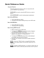
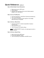
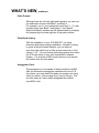
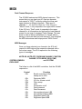
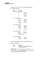
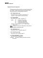
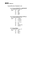
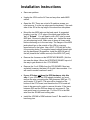
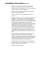
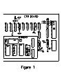
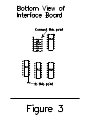
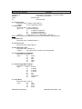
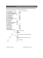
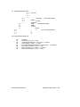
Jupiter-8 MIDI KIT
User's Manual
ENCORE ELECTRONICS 611 LAIRD LN. LAFAYETTE, CA 94549
EMAIL: [email protected] WWW.ENCOREELECTRONICS.COM
INTRODUCTION
You already know that your Jupiter-8 produces unique and
captivating sounds. What you may not know is that the
JP8MK allows you to incorporate this quality sound into
your total sound system with added flexibility and
synchronicity. The MIDI KIT consists of hardware and
software that, once installed, allows your Jupiter-8 to
communicate with your other MIDI instruments,
sequencers, and computers. This MIDI connection allows
you to exchange information (such as notes, program
changes or expression control) between the connected
instruments and devices. This makes it possible for you to
control all of your instruments from a central location, such
as a computer.
In addition to MIDI interfacing, the JP8MK also provides
you with 64 additional patch locations that can be easily
accessed.
All of the new features and additions are detailed in the
sections that follow. The next section of this manual is a
quick reference guide which gives you step-by-step
instructions for performing the new procedures. Unless
specified in this manual, all other functions of the JP-8
remain the same as outlined in the original operation
manual.
Quick Reference Guide
Keys and Controls
The primary keys and controls you will use in conjunction with
your JP-8 MIDI KIT are listed below.
PATCH KEYS are used to select the MIDI function you wish to
perform.
VCA CONTROLLER is used to make parameter adjustments.
How to Enter MIDI Mode
o Tap the [Manual] button lightly.
o The Manual LED flashes indicating that you are in MIDI mode.
How to Exit MIDI Mode
o Tap the [Manual] button lightly.
o The Manual LED stops flashing.
How to Change MIDI Channels
o Make sure that you are in MIDI mode.
o To change the LOWER MIDI channel (the number displayed
on the left) press the [PATCH 3] button.
o Move the VCA Controller until the desired channel number
appears in the display (0-16, 0 being Omni on).
o To change the UPPER MIDI channel (the number displayed
on the right) press the [PATCH 4] button.
o Move the VCA Controller until the desired number appears in
the display.
NOTE1: If you are in "Whole" mode, you can still edit the lower
channel, but the upper channel is the only MIDI channel the JP-8
responds to.
NOTE2: To adjust any MIDI parameters, or to perform a warm reset, the
MEM PROTECT switch on the back panel must be in the OFF position!
Quick Reference, continued
How to Change Banks
o Make sure you are in MIDI mode.
o Press [PATCH 1] to change the JP-8 to Bank 1.
o Press [PATCH 2] to change the JP-8 to Bank 2. (Patch
numbers from Bank 2 are displayed with a dot between the first
and second digits of the patch number).
NOTE: When you exit MIDI mode, the JP-8 remains in the last
bank you selected. You can only change banks from the JP-8
front panel. However, if you are selecting patches from another
MIDI location, you simply press the desired patch numbered
0-127 regardless of what bank the JP-8 is in.
How to Adjust Pitch Bend Scaling
o Make sure you are in MIDI mode.
o Press [PATCH 7].
o Move the VCA Controller until the semi-tone step value you
desire appears in the display (1-12).
How to Adjust Arpeggio
o Make sure you are in MIDI mode.
o Press [Patch 5].
o Move the VCA controller until the pulse per quarter note (ppq)
value you desire appears in the display
(0-24).
Quick Reference, continued
How to Define Breath Control Destination
o Make sure you are in MIDI mode.
o Press [Patch 6].
o Move the VCA controller until the correct display appears
(NONE, FLTR, VCA, BOTH).
How to Access Test Routines
o Hold down the [Patch 1] and [Patch 3] buttons simultaneously.
o Turn on the JP-8 power.
o The current JP-8 software version appears in the display
when the testing is completed.
How to Perform a Warm Reset
o Hold down the [Patch 1], [Patch 2] and [Patch 3] buttons
simultaneously.
o Turn on the JP-8 power.
o The JP-8 returns to its default settings.
NOTE: The MEM PROTECT switch on the back panel must be in
the OFF position!
How to Perform a Sysex Dump
o Make sure you are in MIDI mode.
o Press [TAPE MEMORY SAVE]
o The JP-8 will dump 128 patches to the MIDI out port.
WHAT'S NEW
Expanded Memory
Through the addition of a second memory bank, your JP-8 now
contains 64 new patch locations-- a total of 128 patches in all! In
order to access Bank 2 from the JP-8 front panel, you must be in
MIDI mode (detailed in the next section). The JP-8 remains in
Bank 2 until you manually change it back to Bank 1. This applies
even if you exit MIDI mode.
Patch Selection
With the new expanded memory, there are two ways to select
patches. If you are working from the JP-8 front panel, you can
select a patch numbered 11-18, 21-28, 31-38, 41-48, 51-58,
61-68, 71-78 or 81-88 from Bank 1 or Bank 2. When you are in
Bank 2, patch numbers display with a dot between digit one and
digit two of the patch number. For example, patch 11 in Bank 2
displays as [1.1].
If you are working from another MIDI location, you must select
your patch differently. Instead of selecting a patch numbered 11
through 88, the same patches when called from MIDI are
numbered 0-127. For example, MIDI patch number 0
corresponds to JP-8 patch number 11 in Bank 1. Accordingly,
MIDI patch number 127 corresponds to JP-8 patch number 88 in
Bank 2.
Because MIDI patch selection does not depend on banks, you do
not need to change the active JP-8 memory bank before
selecting a patch from the inactive bank.
WHAT'S NEW, continued
Patch Presets
Although there are still only eight patch presets, you can now
mix and match sounds from Bank 1 and Bank 2.
For example, one of your preset pairs could be [11,1.1), that
is patch eleven from Bank 1 and patch 11 from Bank 2.
Notice that Bank 2 patches are still differentiated by a display
dot between digit one and digit two of the patch number.
Pitch Bend Scaling
With the installation of your JP-8 MIDI KIT, you have
enhanced pitch bend scaling capabilities. Instead of having
to guess at the pitch bend distance, you can select a
semi-tone step value from as little as one semi-tone to a full
octave (1-12). You can change pitch bend scaling from either
the JP-8 front panel or from your central MIDI computer
location. You must be in MIDI mode before you can access
this feature from the front panel.
Arpeggiator Clock
The arpeggiator is now capable of being clocked from MIDI.
After you access the arpeggiator parameter from the JP-8
front panel, you must select the pulse per quarter note (ppq)
value you desire. Values range from 1 ppq to 24 ppq. You
can also select a 0 value which designates the internal
(non-MIDI) clock.
WHAT'S NEW, continued
Breath Controller
You now have the capability of using a breath
controller to send MIDI messages to your JP-8.
Once in the MIDI mode, you can access the breath
control parameter from the front panel. After
activating the parameter, you have the option of
selecting your breath control destination. You have
four destination choices: "NONE", "FLTR", "VCA",
or "BOTH." Selecting "NONE" turns off breath
control. Selecting "FLTR" sends filter sweep
messages. Selecting "VCA" sends volume to VCA
control messages. Selecting "BOTH" sends filter
sweep and volume messages.
Test Routines
The JP-8 now includes test software that can
indicate certain malfunctions. This check the CPU
board, main DAC, and the patch memory of the new
retrofit. After you complete a test, the version of
software your JP-8 is using appears in the display.
Warm Reset
When you perform a warm reset, the JP-8 returns to
its default settings. The defaults are as follows:
MIDI channels to one and two, arpeggiator clock to
setting 0 (internal clock), breath control destination
off, and pitch bend scaling to one semi-tone.
Cassette Load
With the addition of more memory, the JP8 will now
allow your favorite cassette patches to be loaded
into the new memory simply by selecting the second
memory bank and performing a normal cassette
load.
MIDI
Dual Channel Response
The JP8-MK features dual MIDI channel response. This
means that you can treat your JP-8 as two separate
instruments in "SPLIT" mode by setting the lower and
upper timbers to different channels. There are 16
channels, 1 - 16, and 0 for Omni on. If the JP-8 is in
"Whole" mode, it only responds to the upper MIDI channel.
If the JP-8 is in "Dual" mode, it responds to the upper
channel for all information and ignores the lower channel
except for one type of message: Patch Change. This was
done in order to allow modification of a "layer" without
having to send note data on both channels. This simplifies
the MIDI data stream and helps prevent "MIDI Choke."
MIDI Messages
Once you have selected your channels, the JP-8 will
respond to MIDI data on the respective channels with a
five octave range. The JP-8 responds to the following
types of messages:
NOTE ON, NOTE OFF, PROGRAM CHANGE, CONTROL
CHANGE ,PITCH BEND, REAL TIME,
SYSTEM COMMON
and SYSTEM
EXCLUSIVE
The follow is a list of the MIDI controllers that the JP8-MK
responds to:
Control
02h
06h
07h
0Bh
40h
41h
60h
61h
62h
63h
64h
65h
Function
Breath controller to filter
sweep and to VCA.
Data entry MSB
VCA for volume control
Filter sweep
Hold
Portamento on/off
Data Increment
Data Decrement
Non-registered parm LSB
Non-registered parm MSB
Registered parm LSB
Registered parm MSB
MIDI, continued
The follow is a list of the non-registered parameters that
the JP8-MK responds to:
NRP
Function
00 00 Arpeggio range:
1
2
3
4
00-1Fh
20-3Fh
40-5Fh
60-7Fh
00 01 Arpeggio mode:
Up
Down
U/D
Random
00-1Fh
20-3Fh
40-5Fh
60-7Fh
00 02 Assign mode:
Solo
Unison
Poly1
Poly2
00-1Fh
20-3Fh
40-5Fh
60-7Fh
00 03 Key mode:
Dual
00-1Fh
Split
20-3Fh
Whole40-7Fh
00 04 Panel mode:
Lower
Upper
00-3Fh
40-7Fh
The registered parameter that the JP8-MK responds to is
pitch bend sensitivity:
RP
00 00
Function
Pitch bend sensitivity MSB only for
semitone sensitivity.
COMPUTUNE is executed when the tuning button on the
JP-8 front panel is pressed OR when the JP-8 receives the
tune request message, F6h, from MIDI.
MIDI, continued
System Exclusive Commands
There are many system exclusive commands supported by
the JP8-MK. Each system exclusive command is listed
below along with its corresponding description.
o 00 - Single Patch Load
F0 00 00 2F 03 00 <number> <patch data> F7
<number> Patch number to load sysex data
o 01 - Request Data
F0 00 00 2F 03 01 <type> <number> F7
<type>
00
to request 128 patches
01
to request a single patch
02
to request the edit buffer
03
to request the patch presets
<number> 0 when type 0, 2, or 3. Patch number
when type 1.
NOTE: When you request all 128 patches, each patch is
sent individually in ascending order.
o 02 - Edit Buffer Load
F0 00 00 2F 03 02 <edit buffer data> F7
o 03 - Patch Preset Load
F0 00 00 2F 03 03 <preset data> F7
o 04 - Write Edit Buffer to Patch
F0 00 00 2F 03 04 <number> F7
<number> The patch to which you want to save the
edit buffer.
MIDI, continued
System Exclusive Commands, cont.
o 05 - Change KEYMODE or PANELMODE
F0 00 00 2F 03 05 <type> F7
<type>
00
whole
01
split
02
dual
03
upper
04
lower
o 06 - Change Arpeggio Mode and Range
F0 00 00 2F 03 06 <type> F7
<type>
00
1 octave
01
2 octaves
02
3 octaves
03
4 octaves
04
up
05
down
06
up and down
07
random
o 07 - Assign Modes
F0 00 00 2F 03 07 <type> F7
<type>
00
solo
01
unison
02
Poly 1
03
Poly 2
Installation Instructions
o Save user patches.
o Unplug the JP8 from the AC line and any other audio/MIDI
cables.
o Open the JP8. There are a total of 9 machine screws you
must remove: 3 on the top edge near the keyboard, 3 on each
side of the JP8 at the top edge of the aluminum side plates.
o Mount the two MIDI jacks on the back panel. A suggested
location is on the 1-1/4" edge of the back panel below the
"an" of "Roland." You will need to drill a 5/8" hole for each
MIDI jack. Be sure to check for wires, etc... behind the area
you are planning to drill. Make sure to clean all loose metal
before continuing on to the next step. The flanges of the MIDI
jacks should go on the outside of the JP8 to cover any
imperfections in the holes. Use a 5/64" (.078) drill bit for the
four mounting holes. The supplied screws should thread right
into the back panel. [Suggestion: Install the MIDI IN jack to
the left (towards the volume control) of the MIDI OUT jack.]
o Remove the 4 screws on the INTERFACE BOARD. (Not the
two near the hinge.) Move the INTERFACE BOARD up out of
the way to gain access to the CPU BOARD.
o Remove the 3 or 4 ROMs from the CPU BOARD. Most are
socketed; however, the latest JP-8s didn't have sockets. You
will need to socket locations A and C.
o If your JP8 does not have the DCB hardware, skip this
step. If your JP8 has the DCB already installed, you must
remove the wire connecting the Z80 processor NMI [pin 17],
and Inverter IC10 pin10. The wire will be located on the
bottom of the CPU board, and therefore the CPU board will
have to be removed in order to remove this wire. If the trace
between R50 and the Z80 has been cut, reconnect it. The
main point here is to connect pin 17 of the CPU to the NMI
wire from the JP8-MK and nothing else.
o Install the JP8-MK in ROM sockets A and C. Be careful to not
bend any pins.
Installation Instructions, continued
o Solder the 12 wires from the JP8-MK to the appropriate
locations on the CPU board as show in Figure 1. The 12
numbers in Figure 1 correspond to the 12 numbers around the
board in Figure 2. The order is suggested.
o Neatly route the wires from the MIDI jacks along the wiring
harness towards the MIDI board.
o Solder the MIDI jack wires to the MIDI board as shown in
Figure 2.
o Locate the following parts on the INTERFACE BOARD: IC17
and IC22. IC 17-pin12 must be connected to IC 22-pin6.
Locate IC17 - It is almost in the center of the interface board,
below the DAC and to the right. If you view the Interface board
from the bottom you will see a group of 10K resistors
numbered R52 through R57. (See Figure 3) Notice two holes
just above R52, one hole is connected to the left side of R52
and the other looks like it goes nowhere. (It is actually
connected on the top side.) Solder the included wire to the
hole on the right. Now find IC22 from the bottom side of the
board. Solder the other end of this wire to the hole that is
connected to pin 6 (approximately 1/4" below IC22). You can
connect this wire on the top side of the interface board if you
prefer.
o Lower the INTERFACE BOARD back in place and secure it
with the 4 previously removed screws. If the DCB was
installed, you might have trouble securing the interface board.
You can cut the cable that connected the interface board near
the CPU board with a pair of scissors, or you can simply not
attach the two center screws to the interface board.
o Reinstall the nine remaining screws in the JP8 and perform
the WARM RESET. Note: The MEM Protect switch must be in
the OFF position for warm rest to work.
o Reload the customers patches.
MODEL: JP8MK
Date: 7/11/91
Version: 5.10
MIDI IMPLEMENTATION CHART
FUNCTION...
Basic
:Default
Channel :Changed
Default
Mode
Messages
Altered
Note Number
True Voice
Velocity Note On
Note Off
After
Key's
Touch
Ch's
Pitch Bender
Control Change
2, 6, 7, 11, 64, 65, 96, 97,
98, 99,100, 101
Transmitted
x
x
x
x
x
x
x
x
x
x
Recognized
1
1-16
x Mode 3
x
x
0-127
36-96
x
x
x
x
o
o
Remarks
:Warm Reset
:Memorized
Powers up in this mode. JP8MK will operate in all
modes.
+ -1 octave, programmable in semitone intervals.
2- Routes to VCA and/or filter cutoff
6- Data Entry
11- Routes to filter cutoff
96,97- Data inc, Data dec
98,99- NRP
0: Arpeggio range
1: Arpeggio mode
2: Assign mode
3: Key mode
4: Panel mode
100,101 - Pitch bend sensitivity, semitone steps
Prog
Change
True#
System Exclusive
System :Song Position
:Song Select
Common :Tune
System
:Clock
Real Time:Commands
Aux
:Local ON/OFF
Mes:All Notes Off
sages :Active Sense
:Reset
Notes
x
o
0-127
o
o
x
x
x
x
x
o
x
o
x
o
x
x
x
x
x
x
x
x
Echoes all bytes to MIDI OUT port.
Mode 1: OMNI ON, POLY Mode 2: OMNI ON, MONO
Mode 3: OMNI OFF, POLYMode 4: OMNI OFF, MONO
ENCORE ELECTRONICS
See accompanying pages.
Same as COMPUTUNE
Clocks arpeggio with 1-24 PPQ
Starts and stops arpeggio if JP8 is in ARP. mode
o: YES
x: NO
JP8MK MIDI Specification 1991
RECOGNIZED RECEIVE DATA
STATUS
SECOND
THIRD
DESCRIPTION
1000nnnn
0kkkkkkk
0xxxxxxx
Note OFF
Note2
kkkkkkk = 0-127
1001nnnn
0kkkkkkk
0vvvvvvv
Note ONNote1
kkkkkkk = 0-127 vvvvvvv = 0-127
1011nnnn
0ccccccc
0vvvvvvvControl Change
ccccccc: control #
vvvvvvv: control value
1100nnnn
0vvvvvvv
1110nnnn
0vvvvvvv0vvvvvvvPitch Bend
Program Change
0vvvvvvv = 0-127
11111000
Timing Clock
Note3
11111010
Start
Note3
11111011
ContinueNote3
11111100
Stop
*1
*2
*3
Note3
Does not respond to velocity, except for v=0 being a running status NOTE OFF.
Does not respond to velocity.
For arpeggiator
ENCORE ELECTRONICS
JP8MK MIDI Specification 1991
Controller Messages
Bnh
02h
06h
07h
0Bh
40h
41h
60h
61h
62h
63h
64h
65h
Description
Routed to filter cutoff, VCA or both
Data entry for registered/non-registered parameter editing
VCA for volumecontrol
Routed to filter cutoff
Sustain
Portamento on/off
Data increment for parameter editing
Data decrement for parameter editing
Non-registed parameter LSB
Non-registed parameter MSB
Registed parameter LSB
Registed parameter MSB
Non-Registered Parameter #
00 00
Function
Arpeggio range:
1
2
3
4
00-1Fh
20-3Fh
40-5Fh
60-7Fh
00 01
Arpeggio mode:
Up
00-1Fh
Down
20-3Fh
U/D
40-5Fh
Random 60-7Fh
00 02
Assign mode:
Solo
Unison
Poly1
Poly2
00-1Fh
20-3Fh
40-5Fh
60-7Fh
Key mode:
Dual
Split
Whole
00-1Fh
20-3Fh
40-7Fh
Panel mode:
Lower
Upper
00-3Fh
40-7Fh
00 03
00 04
Registered Parameter
00 00
ENCORE ELECTRONICS
Function
Pitch bend sensitivity, MSB only for semitone sensitivity.
JP8MK MIDI Specification 1991
System Exclusive Messages
F0 00 00 2F 03
000000cc
<data>
F7
Description
Sysex header + ENCORE ID + Product # (JP8MK)
cc= (See list of commands)
Exclusive data
End of exclusive
00 - Single Patch Load
F0 00 00 2F 03 00 <number> <patch data> F7
<number>
0-7F for target patch location
01 - Request Data
F0 00 00 2F 03 01 <type> <number> F7
<type> 00
to request 128 patches
01
to request a single patch
02
to request the edit buffer
03
to request the patch presets
<number>
0 when type 0, 2, or 3. Patch number when type 1.
NOTE: When requesting 128 patches, each patch is sent individually in ascending order.
02 - Edit Buffer Load
F0 00 00 2F 03 02 <edit buffer data> F7
03 - Patch Preset Load
F0 00 00 2F 03 03 <preset data> F7
04 - Write Edit Buffer to Patch
F0 00 00 2F 03 04 <number> F7
<number>
The patch to which you want to save the edit buffer.
05 - Change KEYMODE or PANELMODE
F0 00 00 2F 03 05 <type> F7
<type>
00
whole
01
split
02
dual
03
upper
04
lower
06 - Change Arpeggio Mode and Range
F0 00 00 2F 03 06 <type> F7
<type>
00
1 octave
01
2 octaves
02
3 octaves
03
4 octaves
04
up
05
down
06
up and down
07
random
07 - Assign Modes
F0 00 00 2F 03 07 <type> F7
<type>
00
solo
01
unison
02
Poly 1
03
Poly 2
ENCORE ELECTRONICS
JP8MK MIDI Specification 1991
System Exclusive Patch Description
Each patch consists of 28 bytes. One patch will be described here. Each line will show the byte number, a
description, and the value range. The JP8 does not perform range checking on parameters. Each byte is
nibblized, most significant nibble first. All numbers are in hexadecimal.
00: PROTECT BYTE FOR PATCH
FF=Protect, 00=Not protected
01: VCO2 RANGE
00-FF
02: VCO1 MODULATOR-LFO MOD
0D-FF
03: VCO1 MODULATOR-ENV MOD
0E-FF
04: PULSE WIDTH MODULATION
00-FF
05: CROSS MODULATION
00-FF
06: VCO2 FINE TUNE
05-FA
07: SOURCE MIX
00-FF
08: VCF CUTOFF (LPF)
00-FF
09: VCF RESONANCE
00-FF
0A: VCF ENVELOPE MODULATION
00-FF
0B: ENV-1 SUSTAIN
00-FF
0C: ENV-2 SUSTAIN
00-FF
0D: LFO RATE
00-FF
0E: DELAY TIME
00-FF
0F: HIGH PASS FILTER CUTOFF 00-FF
10: VCF LFO MODULATION
00-FF
11: VCF KEY FOLLOW
00-FF
12: VCA LEVEL
00-FF
13: ENV-1 ATTACK
00-FF
14: ENV-1 DECAY
00-FF
15: ENV-1 RELEASE
00-FF
16: ENV-2 ATTACK
00-FF
17: ENV-2 DECAY
00-FF
18: ENV-2 RELEASE
00-FF
19: D7:D6:D5:D4:D3:D2:D1:D0
:0 0 - SINE (LFO WAVEFORM)
:0 1 - RAMP
:1 0 - SQUARE
:1 1 - RANDOM
:0 0
- N/A
:0 1
- VCO2 (VCO MODULATOR FREQ MOD SWITCH)
:1 0 - VCO1
:1 1
- BOTH
:0 0
- N/A
:0 1
- ENV1 (PULSE WIDTH MODULATION SWITCH)
:1 0
- MANUAL
:1 1
- LFO
:0 0
- 16' (VCO1 RANGE)
:0 1
- 8'
:1 0
- 4'
:1 1
- 2'
ENCORE ELECTRONICS
JP8MK MIDI Specification 1991
1A: D7:D6:D5:D4:D3:D2:D1:D0
:0 0
:0 1
:1 0
:1 1
:0 0
:0 1
:1 0
:1 1
:0 0
:0 1
:1 0
:1 1
:0 0
:0 1
:1 0
:1 1
- Not used
- TRIANGLE
(VCO1WAVEFORM)
- RAMP
- PULSE
- SQUARE
- SINE
(VCO2 WAVEFORM)
- RAMP
- PULSE
- NOISE
-0
(VCA LFO MOD SWITCH)
-1
-2
-3
1B: D7:D6:D5:D4:D3:D2:D1:D0
D0
D1
D2
D3
D4
D5
D6
D7
- Not Used
- VCO2 SYNC (0 = ON, 1 = OFF)
- VCO2 RANGE SWITCH (0 = Low Freq, 1 = Normal)
- VCF SLOPE (0 = -24db, 1 = -12db)
- VCF ENVELOPE MOD SWITCH (0 = Envelope2, 1 = Envelope1)
- ENV1 KEY FOLLOW (0 = ON, 1 = OFF)
- ENV1 POLARITY (0 = Inverted, 1 = Normal)
- ENV2 KEY FOLLOW (0 = ON, 1 = OFF)
ENCORE ELECTRONICS
JP8MK MIDI Specification 1991