1
DOCUMENT VET SHEET
for
Karen McConnaughay
Chairman, Kane County Board
Name of Document:
Submitted by:
Date Submitted:
Examined by:
(Date)
Comments:
Chairman signed:
Document refed to:
Rev. 8/05
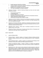
County of Kane
PURCHASING DEPARTMENT
KANE COUNTY GOVERNMENT CENTER
CHRISTOPHER ROSSMAN
Director of Purchasing
719 S. Batavia Avenue, Bldg. A.
Geneva, Illinois 60134
Telephone: (630) 232-5929
Fax: (630) 208-5107
February 25, 2009
To:
Ken Shepro
From: Chris Rossman
Re:
Contract for Bid 09-002 Generator
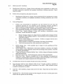
This contract is for Bid 09-002 Generator that was approved by the County Board on
February 10, 2008, as Resolution 09-30. Work for this project is scheduled to start
March 4, 2009.
Attached: Contract 09-002
Sealed Bid 09-002 Generator
Page2
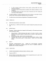
OFFER TO CONTRACT FORM
KANE COUNTY
BID 09-002 GENERATOR
The following offer is hereby made to the County of Kane, Illinois, hereafter called the
Owner.
Submitted By:
1.
The undersigned Bidder proposes and agrees, after having examined the specifications,
quantities and other contract documents, to irrevocably offer to furnish the materials,
equipment and services in compliance with all terms, conditions, specifications and
amendments contained in the bid solicitation documents. The items in this Invitation to Bid,
including, but not limited to, all required certificates, are fully incorporated herein as a
material and necessary part of the contract.
A. The Bidder shall also include with his bid any necessary literature, samples, etc.,
as required within the Invitation to Bid and specification.
B. For purposes of this offer, the terms Offerer, Bidder, Contractor, and Vendor are
used interchangeably.
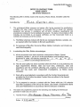
2.
In submitting this Offer, Bidder acknowledges:
A. All bid documents have been examined: Instructions to Bidder, Special
Conditions, Division 1, 26 and 31 of the Specifications and Drawings dated
September 5, 2008,; the following addenda: No.
/
, No. 2- , No. 5
No.
. (Bidder to acknowledge addenda here.)
"'
B. The site and locality has been examined where the Work is to be performed, the
legal requirements (federal, state and local laws, ordinances, rules and
regulations) and the conditions affecting cost, progress or performance of the
Work and has made such independent investigations, as Bidder deems
necessary.
C. Work will be accomplished in accordance with the Contract documents and
complete the Work within the stated Contract time as outlined in the Special
Provision to Bidders.
D. To be prepared to execute a contract with the Owner within ten (1 0) calendar
days after acceptance of the bid by the Owner, and furnish a Performance Bond
and Labor Material Bond in accordance with the Instruction to Bidders.
3.
The bidder will complete this project for the furnishing and installing the 450-kilowatt
generator for total lump sum cost of:
A. Total Bid Amount
l.fvJJog~p Zk;et.v£ LHrN5 A--AI 0 ~t> ~kao
_ _ _ _ _ _ _ _ _ _ _ _ _ _ _ _ _ _ _ _ _ _ _ _ _(Words)
7£1 ()
Dollars ($ "'Z-12. coo.~
0
·,·,
"\ .\
·...\
Sealed Bid 09-002 Generator
Page3
4.
The Contractor guarantees completion of all the work within /~C> Days after receipt of
' be 100% completed by May
.
notice of award or purchase order, and understands work must
10, 2009.
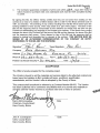
By signing this Bid, the Offeror hereby certifies that they are not barred from bidding on this
contract as a result of a violation of either Section 33E-3 or 33E-4 of the Illinois Criminal Code of
1961, as amended. The awarding of any contract resulting from this Bid will be based upon the
funding available to Kane County, which may award all or part of this project. The terms of the
Bid and the response shall be incorporated by this reference as though fully set forth into the
Contract not withstanding any language in the contract to the contrary. In the event of any conflict
between the terms of the Contract and the terms of the Bid and the response, the terms of the Bid
and the response shall govern. Every element or item of the Bid and the response shall be
deemed a material and severable item or element of the contract. THIS SECTION MUST BE
SIGNED BY AN AUTHORIZED REPRESENTATIVE OF THE COMPANY OR ENTITY
RESPONDING TO THE BID AND THE RESPONSE.
Signature~~
Company
Address
Typed Signature _..L:j),..:::.'l4...::..v::...:'-=-...!..j;...::...:.:os.::.;...S:::::::.__ _ __
goss £tE c.-7'/Z.• c..
I
2. ~- 3'/2. J/Aer-Frz... £tt>
;:I:;(e._
/(AN£ 1//t..t.£ ..
-Po /5
Fax#
Federal I. D./Social Security# 3v- 40t;.3/l \....
Phone# ~3 o -.557
.:rL.
&o 1'/'f
~_So.,.S57- 'Zo/7
Date
I
/z../r:::.~
I
I
ACCEPTANCE
The Offer is hereby accepted for the complete project.
The Vendor is bound to sell the materials and services listed by the attached contract and
based upon the Invitation to Bid, including all terms, conditions, specification,
amendments, and the Vendor's offer is accepted by the County of Kane.
This contract shall henceforth be referred to as Contract Number 09-002. The Vendor
has be~n cautioned not to commence any billable work or to provide any materials or
services until this Vendor receives a purchase order and or notice to proceed.
Karen McConnaughay
Chairman, County Board
Kane County, Illinois
John A. Cunningham
Clerk, County Board
Kane County, Illinois
Date
Date
-- ..
•j'.
'-
1';,
,·•
. '.
POWEBTROtf:
Division of Steiner Electric Company
Generator Sales, Service & Rental
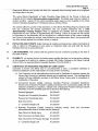
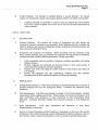
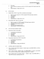
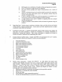
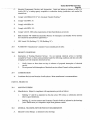
Quote #: CG081222-14A
450kW Sound Housed Diesel Generator & (2) ATS: KANE COUNTY GOVT CENTER
December 30, 2008
I GENEVA
INTERESTED BIDDER
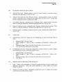
Steiner Electric Co., sole distributor of Kohler generators in Northern iL, is pleased to quote the following equipment
per plans & specifications by Cordogan, Clark & Associates; this quoted equipment is basis for design by engineer.
QTY
UL Listed, NFPA-110 system per Kohler
Q# 25488553
Sub·Total Price
I
I
1
Kohler 450REOZDD Outdoor Diesel Generator, standby rated 1,561 Amps
per phase at 208Y/120V 3ph-4w 450 kW /563 kVA at O.Biag pf, 1800rpm, 60Hz.
Agency Approvals: UL 2200, NFPA-11 0, EPA Certified Tier-3.
=
Provided with these all-Kohler Co. installed items {no bu~outs}:
Steel, box-frame, skid base; isolation mounted to the following:
898gal UL Std. #142 (black) diesel tank with: 5gal spill-fill contain and leak alarm (>24hrs FL)
Sound-housing, light creme beige, locking, enclosed critical silencer, UL flame-rated liner
Sound level, level-2 (25dB reduction); 75dB average, free-field, FL. 23ft. horizontal distance
Enclosure Interior 100A, Main C/B, 208V 3ph-4w panel-board, pre-wired to: battery charger,
block heater, (3) switched AC Interior lights, motorized Inlet louvers, (2) 120V, 20A outlets
Gravity operated radiator hot air output louvers
14L, DOC 6cyl Turbo-Diesel is Tier-3 certified and has air cleaner restriction indicator
'
Fuel accessories: flexible fuel lines, fuel-water separator, (2) fuel filters, fuel primer pump
Unit mounted radiator, high ambient
Factory Phil engine crankcase lubricating oil and antifreeze coolant pre-mix
Engine Driven, Battery Charging Alternator with Voltage Regulator 24vdc /40A
Alternator, PMG #5M4027, with up to 1550kVA peak
Digital Isochronous Governor for +/-0.25% Steady-State Frequency Regulation
Digital Voltage Regulator for +/-0.25% No-Load to Full-load Voltage Regulation
Pre-Alarm senders to controller, NFPA-110
DEC-550, NFPA-110 ali-digital controller with Electric & Engine Meters & Mod-Bus port
Block Heater, 2500W, 208V 1ph, pre-wired to enclosure interior panel-board
Battery Charger, NFPA-110, 24VDC/10A, pre-wired to enclosure Interior panel-board
Two (2) Output Circuit Breakers: (1) 1200-Amp and (1) 400-Amp
Common Fault & Run Relays, 10-Relay Board and Low Fuel dry contact for owner monitoring
Above Items ship built as one unit: 132"H x 93"W x 294"L; 9-tons (excludes diesel fuel)
LOOSE ITEMS {Installed by: others}, SERVICES AND WARRANTY
(1) Asco 1200A 208V 3ph-4w 4-pole, switched neutral, open transition, in-phase monitor,
Nema-1 ATS, #H-300-B3-1200-C1XC-11 BG-14AAI14BA-72E: 87"H x 38"W x 24"0; 700 lbs
(1) Asco 400A Service Entrance with integral 400A utility input C/B rated 35kAIC, 208V 3ph4w 4-pole, switched neutral, Nema-3R, #E-3AUS-C3-400-C1 XM-11 BG-14AAI14BA-72E,
49"H X 36"W X 16"0; 550 lbs.
(1) Kohler Monitor-Ill software and (2) user keys
(2) MODBUS-Ethemet Converters, each require fused 24VDC from generator
(1) RASP, NFPA-110, 16-llght, (needs Belden #9841 cable, no sub & 24vdc from generator)
(2) Remote Emergency Stop Switch (locate & label per inspector requirements)
(1) Battery rack and cables
(2) 12V Starting Batteries Provided & Installed QY Powertron at startup
Certified Factory Test Report at 0%, 25%, 50%, 75% and 100% load and O.Biag PF test
Site Startup, Normal Hours, M-F 8am-4pm, Non-holidays, 14 Days Notice to schedule
Full kW NFPA-110 load bank test at startup, Includes load bank and cables
Set, Owner's Manual, Install Manual and User's Manual for generator and ATS
Freight cost included to site with open flatbed lowboy with NO UNLOAD (by others)
Five Year parts & labor generator only system warranty from startup date per Kohler terms
Five Year parts & labor ATS' only system warrantY from factory ship date per ASCO terms
First Two Years PM agreement with quarterly inspections & (2) changes oil & filters changed
Spares kit with set filters: oil, fuel, air and set: oontroller lamps & fuses & charger fuses
Basic user training visit scheduled by owner M-F 8am-4pm, non-holidays, 7 days notice
Software user training visit scheduled by owner M-F 8am-4pm, non-holidays, 7 days notice
I
··--··--·-··-.
REQUIRED OPTIONAL HARDWARE: Sl!ecial CAT-5 cable {no sub allowed}
Belden #9841 cable, no sub, no splice, between RASP and gene~ator ............ $1.00 per foot
OPTION THAT MAY BE REQUIRED BY STATE FIRE MARSHALL {If needed}
Site pressure test of diesel tank, State Fire Marshall may want to witness this ........ $ 1,250.00
Steiner Electric Company
1275 Touhy Avenue • Elk Grove Village, Illinois 60007 • Phone: 847.956.3098 • Fax: 847.956.5013
--------
r~
,, .'
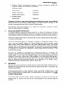
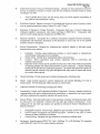
Kohler Power: 450REOZDD: 450 kW: 450REOZBJ): Diesel Generators: Industrial Gene ... Page 1 of3
~DHLER
·.Power
_. .. . .. ·. . . . . . . . . . . . ~ lndustnal
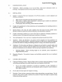
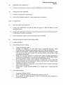
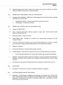
Diesel Generators I 450REOZDD
Return to Results
I
Features
•
Kohler Co. provides one-source responsibility for the
generating system and accessories.
•
The generator set and its components are prototype-tested,
factory-built, and production-tested.
•
The 60Hz generator set offers a UL 2200 listing.
•
The generator set complies with ISO 8528-5, Class G3,
requirements for transient performance.
•
The generator set accepts rated load in one step.
•
The 60 Hz generator set meets NFPA 110, Level 1, when
equipped with the necessary accessories and installed per
NFPA standards.
•
The 60 Hz generator set engine is certified by the
Environmental Protection Agency (EPA) to conform to Tier 3
nonroad emissions regulations.
•
A one-year limited warranty covers all systems and
components. Two-, five-, and ten-year extended warranties
are also available.
Alternator features:
•
The pilot-excited, permanent-magnet (PM) alternator
provides superior short-circuit capability.
•
The brushless, rotating-field alternator has broad range
reconnectability.
•
NEMA MG1 ,IEEE, and ANSI standards compliance for
temperature rise and motor starting.
•
Sustained short-circuit current of up to 300% of the rated
current for up to 10 seconds.
•
Sustained short-circuit current enabling down stream circuit
breakers to trip without collapsing the alternator field.
•
Self-ventilated and dripproof construction.
•
Superior voltage waveform from a two-thirds pitch stator and
skewed rotor.
•
Digital solid-state, volts-per-hertz voltage regulator with
±0.25% no-load to full-load regulation.
•
Brushless alternator with brush less pilot exciter for excellent
http://www.kohlerpower.com/industrial/detail.htm?sectionNumber=l326l&categoryNum ... 12/1.0/2008
:Kohler Power: 450REOZDD: 450 kW: 450REOZDD: Diesel Generators: Industrial Gene ... Page 2 of3
load response.
Other features:
• Controllers are available for all applications.
•
The low coolant level shutdown prevents overheating
(standard on radiator models only).
•
Integral vibration isolation eliminates the need for under-unit
vibration spring isolators.
•
An electronic, isochronous governor delivers precise
frequency regulation.
•
Electronic engine controls manage the engine.
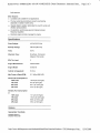
Specifications
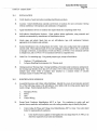
Prime Ratings:
410 kW (513 kVa)
Standby Ratings:
450 kW (563 kVa)
Hertz:
60Hz
Alternator Type:
Brushless, PermanentMagnet, Pilot Exciter
EPA Tier Level:
3
Engine Manufacturer:
Detroit Diesel
Engine Model:
Series 60
Cylinder Arrangement:
6lnline
Max Power at Rated RPM:
511 kWm (685 BHP)
Prime Fuel Consumption at
100% load:
75% load:
50% load:
25% load:
92 Lph (24.3 gph)
122.6 Lph (32.4 gph)
62.1 Lph(16.4gph)
33.3 Lph (8.8 gph)
Standby Fuel Consumption
at
100% load:
75% load:
50% load:
25% load:
131 Lph (34.6 gph)
100.3 Lph (26.5 gph)
68.9 Lph (18.2 gph)
36.3 Lph (9.6 gph)
Options
Generator Controls
Decision-Maker 3+
Decision-Maker 550
http://www.kohlerpower.com/industrial/detail.htm?sectionNumber=l326l&categoryNum ... 12/10/2008
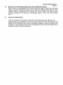
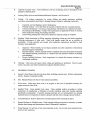
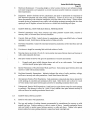
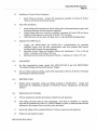
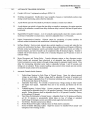
Bond Number
0935102
-----
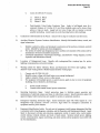
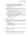
labor and Material Payment Bond
KNOW ALL MEN BY THESE PRESENTS:
That Ross Electric Inc
of 28342 Harter Road, Kaneville IL 60144
(Name and address of the Contractor)
as Principal, hereinafter called Principal, and WEST BEND MUTUAL INSURANCE COMPANY as Surety, hereinafter
called Surety, are held and firmly bound unto
Kane County, 719 S Batavia Ave, Geneva IL 60134
(Name and address of the Owner)
as Obligee, hereinafter called Owner, for the use and benefit of claimants as hereinbelow defined, in the amount of
Two Hundred Twelve Thousand, Dollars and Zero Cents
Dollars($ 212,000.00
(Insert a sum equal to at least one-half of the contract price)
),
for the payment whereof Principal and Surety bind themselves, their heirs, executors, administrators, successors and
assigns, jointly and severally, firmly by these presents.
WHEREAS, Principal has by written agreement dated 02/10/2009
----------- entered into a contract with Owner
for the purchase and installation of 450 kilowatts generator for Building C and Eat 719 S Batavia Ave, Geneva IL 60134
in accordance with drawings and specifications prepared by - - - - - - - - - - - - - - - - - - - - - (Full name and address of Architect/Engineer)
which contract is by reference made a part hereof, and is hereinafter referred to as the Contract.
NOW, THEREFORE, THE CONDITION OF THIS OBLIGATION is such that if the Principal shall promptly make payment
to all claimants as hereinafter defined, for all labor and material used or reasonably required for use in the performance of
the Contract, then this obligation shall be void; otherwise it shall remain in full force and effect, subject, however, to the
conditions outlined on the reverse side of this bond:
Signed and Sealed this
16th
---
day of February
20 09
Principal:
Ro~s~p~/
By.. .
Name Typed: Paul Ross
Witness:
(SEAL)
Owner
Title
Mutual lnsuranc~ompany ~
.,
Witness:
I
-\"~t---
(SEAL)
, Attorney in fact
c
Title
MICHIGAN ONLY: This policy is exempt from the filing requirements of Section 2236 of the Insurance Code of 1956,
1956 PA 218 and MCL 500.2236.
NB 0011 02 08
8401 Greenway Blvd. Suite 1100
Page 1 of 2
I
Middleton, Wl53562
I
Phone: (608) 410-3410
I
Fax: (877) 674-2663
1www.wbmi.com
'J
I i,,
'I,
b. After the expiration of one (1) year following the
date on which Principal released work on said
Contract, it being understood, however, that if any
limitation embodied in this bond is prohibited by
any law controlling the construction hereof such
limitation shall be deemed to be amended so as
to be equal to the minimum period of limitation
permitted by such law.
c. Other than in a state court of competent jurisdiction in and for the county or other political subdivision of the state in which the project, or any part
thereof, is situated, or in the Untied States District
Court for the district in which the project, or any
part thereof, is situated, and not elsewhere.
4. The amount of this bond shall be reduced by and to
the extent of any payment or payments made in good
faith hereunder, inclusive of the payment by Surety of
mechanics' liens which may be filed of record against
said improvement, whether or not claim for the
amount of such lien be presented under and against
this bond.
CONDITIONS
1. A claimant is defined as one having a direct contract
with the Principal or with a Subcontractor of the Principal for labor, material, or both, used or reasonably
required for use in the performance of the Contract,
labor and material being construed to include that
part of water, gas, power, light, heat, oil, gasoline,
telephone service or rental of equipment directly applicable to the Contract.
2. The above named Principal and Surety hereby jointly
and severally agree with the Owner that every claimant as herein defined, who has not been paid in full
before the expiration of a period of ninety (90) days
after the date on which the last of such claimant's
work or labor was done or performed, materials were
furnished by such claimant may sue on this bond for
the use of such claimant, prosecute the suit to final
judgement for such sum or sums as may be justly
due claimant, and have execution thereon. The
Owner shall not be liable for the payment of any
costs or expenses of any such suit.
3. No suit or action shall be commenced hereunder by
any claimant.
a. Unless claimant, other than one having a direct
contract with the Principal, shall have given written notice to any two of the following: The Principal, the Owner, or the Surety above named,
within ninety (90) days after such claimant did or
performed the last of the work or labor, or furnished the last of the materials for which said
claim is made, stating with substantial accuracy
the amount claimed and the name of the party to
whom the materials were furnished, or for whom
the work or labor was done or performed. Such
notice shall be served by mailing the same by
registered mail or certified mail, postage prepaid,
in an envelope addressed to the Principal, Owner
or Surety, at any place where an office is regularly maintained for the transaction of business, or
served in any manner in which legal process may
be served in the state in which the aforesaid project is located, save that such service need not be
made by a public officer.
Page 2 of2
8401 Greenway Blvd. Suite 1100
NB 0011 02 08
I
Middleton, WI 53562
I
Phone: (608) 410-3410
I
Fax: (877) 67 4-2663
1 www.wbmi.com
Bond Number 0935102
-------
Performance Bond
KNOW ALL MEN BY THESE PRESENTS:
That Ross Electric Inc
of 28342 Harter Road, Kaneville IL 60144
(Name and address of the Contractor)
as Principal, hereinafter called Principal, and WEST BEND MUTUAL INSURANCE COMPANY as Surety, hereinafter
called Surety, are held and firmly bound unto Kane County, 719 s Batavia Ave, Geneva IL 60134
(Name and address of the Owner)
as Obligee, hereinafter called Owner, in the amount of - - - - - - - - - - - - - - - - - - - - - - - _T_w_o_H_un_d_re_d_T_w_e_l_ve_T_h_o_u_s_an_d_,_D_o_lla_r_s_a_nd_Z_e_r_o_C_e_n_ts_____________ Dollars ($ 212,000.00
),
for the payment whereof Contractor and Surety bind themselves, their heirs, executors, administrators, successors and
assigns, jointly and severally, firmly by these presents.
02/10/2009
WHEREAS, Contractor has by written agreement dated
entered into a contract with Owner
for purchase & installation of 450 kilowatts generator for Building C & Eat 719 S Batavia Ave, Geneva IL 60134
---------
in accordance with drawings and specifications prepared by - - - - - - - - - - - - - - ' - - - - - - - - - (Full name and address of Architect or Engineer)
which contract is by reference made a part hereof, and is hereinafter referred to as the Contract.
NOW, THEREFORE, THE CONDITION OF THIS OBLIGATION is such that, if Contractor shall promptly and faithfully
perform said contract, then this obligation shall be null and void; otherwise it shall remain in full force and effect.
The Surety hereby waives notice of any alteration or extension of time made by the Owner.
Whenever Contractor shall be, and declared by Owner to be in default under the Contract, the Owner having performed
Owner's Obligations thereunder, the Surety may promptly remedy the default, or shall promptly
1. Complete the Contract in accordance with its terms and conditions, or
2. Obtain a bid or bids for completing the Contract in accordance with its terms and conditions, and upon determination by
Surety of the lowest responsible bidder, or, if the Owner elects, upon determination by the Owner and the Surety jointly
of the lowest responsible bidder, arrange for a contract between such bidder and Owner, and make available as Work
progresses (even though there should be a default or a succession of defaults under the contract or contract of completion arranged under this paragraph) sufficient funds to pay the cost of completion less the balance of the contract
price; but not exceeding, including other costs and damages for which the surety may be liable hereunder, the amount
set forth in the first paragraph hereof. The term "balance of the contract price", as used in this paragraph, shall mean
the total amount payable by Owner to Contractor under the Contract and any amendments thereto, less the amount
properly paid by Owner to Contractor.
Any suit under this bond must be instituted before the expiration of one (1) year from the date on which final payment
under the contract falls due.
No right of action shall accrue on this bond to or for the use of any person or corporation other than the Owner named
herein of the heirs, executors, administrators or successors of the Owner.
Signed and Sealed this
16th
20 09
day of February
Principal:
Ros~H~~<
_B;;;...y'-'-.--;;,"---4'=.;....;:'-"'-__,_=·=-=------- (SEAL)
Name Typed: Paul Ross
, Owner
Title
Witness:
Surety:
West Ben
Witness:
~~~
utual lnsurC!nce ~pany
,Attomeyin~~
B:
(SEAL)
MICHIGAN ONLY: This policy is exempt from the filing requirements of Section 2236 of the Insurance Code of 1956,
1956 PA 218 and MCL 500.2236.
NB 0012 02 08
8401 Greenway Blvd. Suite 1100
Page 1 of 1
1
Middleton, Wl53562
1
Phone: (608) 410-3410
1
Fax: (877) 674-2663
1
www.wbmi.com
\
'.
(
'• 'I
Sealed Bid 09-002 Generator
PageS
INSTRUCTIONS TO BIDDERS
COUNTY OF KANE
COMPETITIVE SELECTION PROCEDURE • BID
TERMS AND CONDITIONS
1.
AUTHORITY. This Invitation for Bid is issued pursuant to applicable provisions of the Kane
County Purchasing Ordinance.
2.
BID OPENING. Sealed bids will be received at the Kane County Purchasing Department until the
date and time specified at which time they shall be opened in public. Late bids shall be rejected
and returned unopened to the sender. Kane County does not prescribe the method by which bids
are to be transmitted; therefore, it cannot be held responsible for any delay, regardless of the
reason, in transmission of the bids.
3.
BID PREPARATION. Bids must be submitted on this form and all information and certifications
called for must be furnished. Bids submitted in any other manner, or which fail to furnish all
information or certificates required, may be summarily rejected. Bids may be modified or
withdrawn prior to the time specified for the opening of bids. Bids shall be filled out legibly in ink or
type-written with all erasures, strike overs and corrections initialed in ink by the person signing the
bid. The bid shall include the legal name of the bidder, the complete mailing address, and be
signed in ink by a person or persons legally authorized to bind the bidder to a contract. Name of
person signing should be typed or printed below the signature.
4.
BID ENVELOPES. Envelopes containing bids must be sealed and addressed to the County of
Kane Purchasing Department. The name and address of the bidder and the Invitation Number
must be shown in the upper left corner of the envelope.
5.
ERRORS IN BIDS. Bidders are cautioned to verify their bids before submission. Negligence on
the part of the bidder in preparing the bid confers no right for withdrawal or modification of the bid
after it has been opened. In case or error in the extension of prices in the bid, the unit prices will
govern.
6.
RESERVED RIGHTS. The County of Kane reserves the right at any time and for any reason to
cancel this Invitation for Bids, accept or reject any or all bids or any portion thereof, or accept an
alternate bid. The County reserves the right to waive any immaterial defect in any bid. Unless
otherwise specified by the bidder or the County, the County has ninety (90) days to accept as
stated on page 14 under Bid Acceptance .Period. The County may seek clarification from any
bidder at any time and failure to respond promptly is cause for rejection.
7.
INCURRED COSTS. The County will not be liable for any costs incurred by bidders in replying to
this Invitation for Bids.
8.
AWARD. It is the intent of the County to award a contract to the lowest responsive responsible
bidder meeting specifications. The County reserves the right to determine the lowest responsive
responsible bidder on the basis of an individual item, groups of items, or in any way determined to
be in the best interests of the County. Award will be based on the following factors (where
applicable): (a) adherence to all conditions and requirements of the bid specifications; (b) price;
(c) qualifications of the bidder, including past performance, financial responsibility, general
reputation, experience, service capabilities, and facilities; (d) delivery or completion date; (e)
product appearance, workmanship, finish, taste, feel, overall quality, and results of product
testing; (f) maintenance costs and warranty provisions; and (g) repurchase or residual value.
Sealed Bid 09-002 Generator
Page7
· 9.
PRICING. The price quoted for each item is the full purchase price, including delivery to
destination, and includes all transportation and handling charges, premiums on bonds, material or
service costs, patent royalties and all other overhead charges of every kind and nature. Unless
otherwise specified, prices shall remain firm for the contract period.
10.
DISCOUNTS. Prices quoted must be net after deducting all trade and quantity discounts. Where
cash discounts for prompt payment are offered, the discount period shall begin with the date of
receipt of a correct invoice or receipt or final acceptance of goods, whichever is later.
11.
TAXES. Kane County is not subject to Federal Excise Tax. Per Illinois Revised Statutes, Chapter
120, Paragraph 441: Kane County is exempt from state and local taxes.
12.
SPECIFICATIONS. Reference to brand names and numbers is descriptive, but not restrictive,
unless otherwise specified. Bids on equivalent items will be considered, provided the bidder
clearly states exactly what is proposed to be furnished, including complete specifications. Unless
the bidder specified otherwise, it is understood the bidder is offering a referenced brand item as
specified or is bidding as specified when no brand is referenced, and does not propose to furnish
an "equal." The County reserves the right to determine whether a substitute offer is equivalent to
and meets the standard of quality indicated by the brand name and number referenced.
13.
SAMPLES. Samples of items, when called for, must be furnished free of expense and, if not
destroyed in the evaluation process, will, upon request, be returned at the bidder's expense.
Request for the return of samples must accompany the sample and include UPS Pickup Slip,
postage or other acceptable mode of return. Individual samples must be labeled with bidder's
name, invitation number, item reference, manufacturer's brand name and number.
14.
INTERPRETATION OR CORRECTION OF BIDDING DOCUMENTS. Bidders shall promptly
notify the County of any ambiguity, inconsistency of error which they may discover upon
examination of the bidding documents. Interpretations, corrections and changes will be made by
addendum. Each bidder shall ascertain prior to submitting a bid that all addenda have been
received and acknowledged in the bid.
15.
VARIANCES. State or list by reference on the reverse side of this form any variations to
specifications, terms and/or conditions.
16.
INDEMNIFICATION. The Seller shall indemnify and hold harmless the County, its agents,
officials, and employees, from and against all injuries, losses, claims, suits, costs and expenses
which may accrue against the County as a consequence of granting the Contract.
Contractor and/or Servicer's and/or Seller (as case may be), agrees to save, hold harmless,
defend and indemnify the County of Kane and its Officers, Agents, and Employees, from any and
all liability or loss incurred by the County of Kane resulting from Contractor's and/or Servicer's
and/or Seller's noncompliance with any laws or regulations of any governmental authority having
jurisdiction over Contractor's and/or Servicer's and /or Seller's performance of this contract and
Contractor's and/or Seller's violation of any of the terms and conditions of this Agreement, and
from the Contractor's and/or Servicer's and/or Seller's negligence arising from, in any manner and
in any way connected with, the terms and conditions of this Agreement and arising from the
Contractor's and/or Servicer's and/or Seller's performance thereunder.
17.
DEFAULT. TimE! is of the essence of this contract and if delivery of acceptable items or rendering
of services is not completed by the time promised, the County reserves the right, without liability,
in addition to its other rights and remedies, to terminate the contract by notice effective when
received by Seller, as to stated items not yet shipped or services not yet rendered and to
purchase substitute items or services elsewhere and charge the Seller with any or all losses
incurred.
Sealed Bid 09·002 Generator
PageS
18.
INSPECTION. Materials or equipment purchased are subject to inspection and approval at the
County's destination. The County reserves the right to reject and refuse acceptance of items
which are not in accordance with the instructions, specifications, drawings or data of Seller's
warranty (express or implied). Rejected materials or equipment shall be removed by, or at the
expense of, the Seller promptly after rejection.
19.
WARRANTY. Seller warrants that all goods and services furnished hereunder will conform in all
respects to the terms of the solicitation, including any drawings, specifications or standards
incorporated herein, and that they will be . free from latent and patent defects in materials,
workmanship and title, and will be free from such defects in design. In addition, Seller warrants
that said goods and services are suitable for, and will perform in accordance with, the purposes
for which they are purchased, fabricated, manufactured and designed or for such other purposes
as are expressly specified in this solicitation. Th~ County may return any nonconforming or
defective items to the Sellerorrequire correction or replacement of the item at the time the defect
is discovered, all at the Seller's risk and expense. Acceptance· shall not relieve the Seller of its
responsibility.
Contractor and/or Seller (as case may be) expressly warrants that all goods and services (real
property and all structures thereon) will conform to the drawings, materials, performance and any
other specifications, samples or other description furnished by the County, and will be fit and
sufficient for the purpose intended, merchantable, of good material and workmanship. Contractor
and/or Seller (as case may be) agrees that these warranties shall run to Kane County, its
successor, assigns, customers and users of the products or services and that these warranties
shall survive acceptance of the goods or performance of the services.
26:
REGULATORY COMPLIANCE. Seller represents and warrants that the goods or services
furnished hereunder (including all labels, packages and container for said good) comply with all
applicable standards, rules and regulations in effect under the requirements of all Federal, State
and local laws, rules and regulations as applicable, including the Occupational Safety and Health
Act as amended, with respect to design, construction, manufacture or use for their intended
purpose of said goods or services. Seller shall furnish "Material Safety Data Sheet" in compliance
with the Illinois Toxic Substances Disclosure to Employees Act.
21.
EQUAL EMPLOYMENT OPPORTUNITY. (Res.No. 82-90, 6-10-80; Res. No. 81-79, 6-9-81: Res.
No. 82-90, 6-8-82; 05-303, 09-23-05) State law references--Fair Employment Practices Act, Ill.
Rev.Stat. Ch. 48, Sec.851 et seq.; requirements for public contracts, Ill. Rev. Stat. Ch. 48, Sec.
854.
22.
PREVAILING WAGE RATES
WHEREAS, it is the policy of the State of Illinois as declared in "An ACT regulating wages of
laborers, mechanics and other workman employed in any public works by the. State, County, City
or any political subdivision or by any work under construction for public works" approved June 26,
1941, that a wage of no less that the general prevailing hurly rate as paid for work of a similar
character in a locality in which work is performed, shall be paid to all laborers, workmen and
mechanics employed by and on behalf of any and all public body engaged in public works,
exclusive of maintenance work.
PREVAILING WAGE ACT AMENDMENT: HB-1855 (PA 095-0635) amends the Prevailing Wage Act
and requires Public Works contractors, before work commences, to file with the Public Body,
certification that they have a substance abuse program and provide drug testing. This Act applies to a
contract to perform work on a public works project for which bids are opened on or after January 1,
2008, or if bids are not solicited for the contract to perform such work entered into on or after
January 1, 2008. The provisions of this Act apply only to the extent there is no collective bargaining
agreement in effect dealing with the subject matter of this Act.
Sealed Bid 09-002 Generator
Page9
Responsh/e-sfaCfersmusfinclude-wHf1lheirbfcfa- separate sheet showing Traoes1o-oeemployea-----------and wage rates to be paid.
The current Illinois Department of Labor Prevailing Wage Rates for the County of Kane are
available at their website http://www.state.il.us/agency/idol/. Prevailing wage rates are subject to
revision monthly. Copies of the current prevailing wage rages are also available at the Kane
County Purchasing Department, 719 Batavia Avenue, Geneva, Illinois.
Any contact within the purview of this resolution or of the Illinois Prevailing Wage Act shall provide
that any contractor will employ apprentices who are properly indentured into a Joint
Apprenticeship Training Program which is registered and certified with the United States
Department of Labor, Bureau of Apprenticeship and Training. Failure to comply with the request
for information or documentation will be construed as a material breach of the contract enabling
the County to terminate the contract, seek forfeiture of any performance bond, and proceed with
any other. remedy against the contractor at law or inequity.
23.
ROYALTIES AND PATENTS. Seller shall pay all royalties and license fees. Seller shall defend all
suits or claims for infringement of any patent or trademark rights and shall hold the County
harmless from loss on account thereof.
24.
LAW GOVERNING. This contract shall_ be governed by and construed according to the laws of
the State of Illinois.
25.
ELIGIBILITY. By signing this bid, the bidder hereby certifies that they are not barred from bidding
on this contract as a result of a violation of Article 33E, Public Cor:ttracts of the Illinois Criminal
Code of 1961, as amended (Illinois Compiled Statutes, 720 ILCS 5/33E-1 ).
26.
CERTIFICATE OF INSURANCE REQUIRED BY KANE COUNTY
Contractor to furnish and deliver prior to commencement of work, a completed Certificate of
Insurance satisfactory to the requirements of County of Kane containing:
a) The Contractor and all subcontractors shall provide a Certificate of Insurance naming the
Owner (Kane County) as certificate holders and as additional insured. The certificate shall
contain a 30-day notification provision to the owner (Kane County) prior to cancellation or
modification of the policy.
b) Commercial General Liability insurance including Products/ Completed Operations,
Owners and Contractors Protective Liability and Broad Form Contractual Liability with the
exclusion pertaining to explosion, collapse and underground Property Damage hazards
eliminated. The limit of liability shall not be less than the following:
General Aggregate
$2,000,000
Products and Completed Operations
$2,000,000
Personal and Advertising Injury
$1,000,000
Each Occurrence
$1,000,000
or- Combined Single Limit
$1,000,000
c) Business Automotive Liability Insurance including owned,
automobiles with limits of not less than the following:
Each Person for Bodily Injury
$1,000,000
Each Occurrence for Bodily Injury
$1 ,000,000
Each Occurrence for Property Damage $1,000,000
or - Combined Single Limit
$1,000,000
hired and non-owned
Sealed Bid 09-002 Generator
Page 10
d) Statutory Worker's Compensation Insurance, including occupational disease with
Employer's Liability limit not less· than the following:
Employers Liability:
Each Accident
$1,000,000
Disease - Policy Limit
$1,000,000
Disease Each Employee
$1,000,000
e) Umbrella Liability
Excess Limits
$2,000,000
Contractor to furnish a copy of the Endorsement showing Kane County, as an additional
named insured on the General Liability policy; ·or provide separate coverage, in the
amounts enumerated above, with an Owner's Protective policy.
The Contractor shall cease operations on the project if the insurance is cancelled or reduced
below the required amount of coverage.
27.
EQUAL EMPLOYMENT OPPORTUNITY
The equal employment opportunity clause required by the Illinois Fair Employment Practices
Commission is hereby incorporated by reference in all contract made by the county of and in all
bid specifications therefore furnished by the county to all bidders, contractors and subcontractors.
The County of Kane, State of Illinois, represents that it and the employing agencies responsible to
it, conform to the following:
We do not discriminate against any employee or applicant for employment because of race,
creed, color, age, disability, religion, sex, national origin/ancestry, sexual orientation, marital
status, veteran status, political affiliation, or any other legally p~otected status. We will take
whatever action is necessary to ensure that applicants and employees are treated appropriately
regarding all terms and conditions of employment. We will post in conspicuous places, available
to employees and applicants for employment, notices setting forth the provisions of this
nondiscrimination clause.
We will, in all solicitations or advertisements for employees placed by or on behalf of the
employing agencies, state that all qualified applicants will receive consideration for employment
without regard to race, creed, age, disability, religion, sex, national origin/ancestry, sexual
orientation, marital status, veteran status, political affiliation, or any other legally protected status.
(Res.No. 82-90, 6-10-80; Res. No. 81-79, 6-9-81: Res. No. 82-90, 6-8-82; 05-303, 09-23-05)
State law references--Fair Employment Practices Act, Ill. Rev.Stat. Ch. 48, Sec.851 et seq.;
requirements for public contracts, Ill. Rev. Stat. Ch. 48, Sec. 854.
28.
BID DEPOSIT
All bids must be accompanied by a Bank Cashier's Check, Bank Draft, Certified Check, or
Bid Bond for not less than five (5%) percent of the amount of the Bid, or according to the
schedule as provided.
·
Accompanying this Bid is a Bank Cashier's Check, Bank Draft, Certified Check, or Bid
Bond, complying with the requirements of the specifications, made payable to the KANE
COUNTY TREASURER.
In the event that one check, draft or bond is intended to cover two or more bids, the
amount must be equal to the sum of the bid. guarantees of the individual sections
covered.
Sealed Bid 09-002 Generator
··-------------·-·-----
29.
- - - - ------------------- - - - - - - -
···-----·--::-:::----
-------~-~~e 11 __________
EXECUTION OF A PERFORMANCE BOND AND LABOR AND MATERIALS BOND
When noted in the specifications, the County reserves the right to require the successful
bidder to supply a Performance Bond and a Labor and Materials Bond within ten (10)
calendar days of acceptance of the Vendor's bid by the County. The bonds, unless
otherwise specified by the Director of Purchasing, shall be 100% of the total contract
price.
30.
FAILURE TO FURNISH BOND
In the event that the Vendor fails to furnish the abovementioned bonds within ten (10)
calendar days after acceptance of the bid by the County, then the bid deposit of the
bidder shall be retained by the County as liquidated damages, it being now agreed that
said sum is a fair estimate of the amount of damages that said County will sustain due to
the Bidder's failure to furnish said bonds.
Sealed Bid 09-002 Generator
Page 12
SPECIAL CONDITIONS
Bid 09-002 Generator
1. PERMITS: The County will, prior to the start of any work, obtain necessary State, County
and City pennits, as required to perfonn the work outlined under this contract. It shall be
the Contractor's responsibility to conduct the operations in such a manner so as to comply
with all provisions and conditions of the pe1mits.
2. DOWNTIME: The Contractor shall limit power outages to the County's building(s) during
non-business hours only. Currentbusiness hours are Monday- Friday 8:30a.m. to 4:30
p.m. Also all outages shall be coordinated with the County's Representative with at least a
twenty-four (24) hour notice.
3. SITE PARKING: The Contractor's employees shall park in the lower parking lot east of
the project site.
4. SITE STORAGE AREAS: The County will provide approximately six (6) parking spaces
as a storage area for the Contactor behind building E, on the south side only.
5. CLOSING OF ROADWAY AND PARKING LOT: The Contractor shall not close off any
area unless he has all equipment and materials on hand so as to expedite his operations and
having any closer for a minimum amount of time.
The Contractor will provide a twenty-four (24) hour notice, to the appropriate County
Representative, prior to closing off any area on County property:
6. BARRICADES AND FENCING: The Contractor shall use the appropriate devices to
protect the safety of County employees and the public that will be entering and leaving the
County buildings and using.parldng areas near the project site.
7. EQUIPMENT DATA SHEETS: The Contractor shall provide dimensional drawings· and
specification sheets of the generator they are including with their bid, so that it is of an
appropriate size to fit in the location it is to be placed.
Should the Contractor desire. to use material or equipment other than what specified, he
shall clearly indicate in his bid on the Offer to Contract form. Full particulars on alternate
equipment shall be submitted with the bid.
7. CLEAN UP: The clean up shall consist of removing all debris from under the jobsit~, to
include removal of all excess dirt, pipe pieces, lumber scraps, paper cups, etc., left by the
Contractor's crews. Roadways, bike paths and sidewalks shall be swept daily or frequently
if necessary. Clean up shall be pe1fonn as the work progresses, and a final clean up shall
be done after all operations are completed.
Sealed Bid 09-002 Generator
Page 13
-------------
SPECIFICATIONS
FOR
NEW GENERATOR FOR BUILDINGS 'C' AND 'E'
FOR
Kane County Government Center
1 79 S. Batavia Ave.,
Geneva, IL 60134
Specification Divisions 1 through 31
DATED: December 8 2008
PREPARED BY:
CORDOGAN, CLARK & ASSOCIATES
960 RIDGEWAY AVENUE, AURORA, ILLINOIS 60506
TABLE OF CONTENTS
SECTION NO.
SECTION TITLE
PROJECT DRAWING INDEX: DATED December 8, 2008
Project DraWing Index: Dated September 5, 2008
Structural: SlOl.
Electrical: El.O, E2.0, E3.0.
DIVISION 1
015000
017300
017823
DIVISION26
260500
260523
260526
260529
260533
260553
263213
263600
DIVISION31
312000
GENERAL REQUIREMENTS
TEMPORARY FACILITIES AND CONTROLS
EXECUTION
OPERATION AND MAINTENANCE DATA
ELECTRICAL
COMMON WORK RESULTS FOR ELECTRICAL
CONTROL-VOLTAGE ELECTRICAL POWER CABLES
GROUNDING AND BONDING FOR ELECTRICAL SYSTEMS
HANGERS AND SUPPORTS FOR ELECTRICAL SYSTEMS
RACEWAY AND BOXES FOR ELECTRICAL SYSTEMS
IDENTIFICATION FOR ELECTRICAL SYSTEMS
ENGINE GENERATORS
TRANSFER SWITCHES
EARTHWORK
EARTH MOVING (TRENCHING)
Sealed Bid 09-002 Generator
Page 14
SECTION 015000- TEMPORARY CONTROLS
PART I-GENERAL
1.1
SUMMARY
A.
Section includes requirements for temporary utilities, support .facilities, and security and
protection facilities.
B..
Related Sections:
1.
1.2
Division 26 for work restrictions and limitations on 11-tility interruptions.
QUALITY ASSURANCE
A.
Provide OSHA approved temporary barricades and barriers for the safety and protection of
workers and passers-by.
PART 2- PRODUCTS
SECURITY AND PROTECTION FACILITIES INSTALLATION
2.1
A.
Environmental Protection: Provide protection, operate temporary facilities, and conduct
construction as required to comply with environmental .regulations and that minimize possible air,
waterway, and su~soil contamination or pollution or other undesirable effects.
B.
Temporary Erosion and Sedimentation Control: Comply with requirements of 2003 EPA
Construction General Permit or authorities having jurisdiction, whichever is more stringent.
c.
Temporary Erosion and Sedimentation Control: Provide measures to prevent soil erosion and
discharge of soil-bearing water runoff and airborne dust to undisturbed areas and to adjacent
properties and walkways.
1.
2.
3.
4.
Verify that flows of water redirected from construction areas or generated by construction
activity do not enter or cross tree- or plant- ptotection zones.
Inspect, repair, and maintain erosion- and sedimentation-control measures during
construction until permanent vegetation has been established.
Clean, repair, and restore adjoining properties and roads affected by erosion and
sedimentation from the project site during the course of the project.
Remove erosion and sedimentation controls and restore and stabilize areas disturbed during
removal.
D.
Stormwater Control: Comply with requirements of authorities having jurisdiction. Provide
barriers in and around excavations and subgrade construction to prevent flooding by runoff of
stormwater from heavy rains.
E.
Tree and Plant Protection: Install temporary fencing located as indicated or outside the drip line
of trees to protect vegetation from damage from construction operations. Protect tree root systems
from damage, flooding, and erosion.
Sealed Bid 09-002 Generator
Page 15
..
F.
·-------··----·---------·-----
Site Protection: Prior to commencing earthwork, furnish and install approved fencing, barricades,
or barriers in a manner that will prevent people and animals from easily entering site except by
designated entrances.
1.
2.
3.
4.
Security Enclosure and Lockup: Install temporary enclosure around partially completed
areas of construction .that prevent unauthorized entrance, vandalism, theft, and similar
violations that create hazards for owner's staff and the general public. Lock entrances at
end of each work day.
Barricades, Warning Signs, and Lights: Comply with requirements of authorities having
jurisdiction for erecting structurally adequate barricades, including warning signs and
lighting.
Temporary Egress: Maintain temporary egress from existing occupied facilities as
indicated and as required by authorities having jurisdiction.
Temporary Enclosures: Provide temporary enclosures for protection of construction, in
progress and completed, from exposure, foul weather, other construction operations, and
similar activities. Provide temporary weathertight enclosure for building exterior.
OPERATION, TERMINATION, AND REMOVAL
2.2
A.
Termination and Removal: Remove each temporary protection when need for its service has
ended no later than Substantial Completion. Repair damaged Work, clean exposed surfaces, and
replace construction that cannot be satisfactorily repaired.
1.
2.
Materials and facilities that constitute temporary facilities are property of Contractor.
Remove materials contaminated with road oil, asphalt and other petrochemical compounds,
and other substances that might impair growth of plant materials or lawns. Repair or
replace landscaping, street paving, curbs, and sidewalks damaged by or during the work.
END OF SECTION 015000
Sealed Bid 09-002 Generator
Page 16
SECTION 017300- EXECUTION
PART 3- GENERAL
SUMMARY
3.1
A.
Section includes general administrative and procedural requirements governing execution of the
Work including, but not limited to, the following:
1.
2.
3.
4.
5.
6.
7.
8.
Construction layout.
Field engineering and surveying.
Installation of the Work.
Cutting and patching.
Progress cleaning.
Starting and adjusting.
Protection of installed construction.
Correction of the Work.
QUALITY ASSURANCE
3.2
A.
Cutting and Patching: Comply with requirements for and limitations on cutting and patching of
construCtion elements.
2.
3.3
a.
Operational Elements: Do not cut and patch operating elements and related
components in a manner that results in reducing their capacity to perform as intended
or that results in increased maintenance or decreased operational life or safety.
b.
Other Construction Elements: Do not cut and patch other construction elements or
components in a manner that could change their load-carrying capacity, that results
in reducing thej.r capacity to perform as intended, or that results in increased
maintenance or decreased operational life or safety.
Visual Elements: Do not cut and patch construction in a manner that results in visual
evidence of cutting and patching. Do not cut and patch exposed construction in a manner
that would, in Architect's opinion, reduce the building's aesthetic qualities. Remove and
replace construction that has been cut and patched in a visually unsatisfactory manner.
WARRANTY
A.
Existing Warranties: Remove, replace, patch, and repair materials and surfaces cut or damaged
during installation or cutting and patching operations,. by methods and with materials so as not to
void existing warranties.
PART 4 -PRODUCTS
4.1
MATERIALS
A.
General: Comply with requirements specified in other Sections.
Sealed Bid 09-002 Generator
Page 17
B.
In-Place Materials: Use materials for patching identical to in-place materials. For exposed
surfaces, use materials that visually match in-place adjacent surfaces to the fullest extent possible.
1.
If identical materials are unavailable or cannot be used, use materials that, when installed,
will provide a match acceptable to the Owner for the visual and functional performance of
in-place materials.
PART 5 -EXECUTION
5.1
EXAMINATION
A.
Existing Conditions: The existence and location of underground and other utilities and
construction indicated as existing are not guaranteed. Before beginning sitework, investigate and
verify the existence and location of underground utilities, mechanical and electrical systems, and
other construction affecting the Work.
B.
Examination and Acceptance of Conditions: Before proceeding with each component of the
Work, examine substrates, areas, and conditions for compliance with requirements for installation
tolerances and other conditions affecting performance. Record observations.
1.
2.
3.
4.
Verify compatibility with and suitability of substrates, including compatibility with existing
finishes or primers.
Examine roughing-in for mechanical and electrical systems to verify actual locations of
connections before equipment and fixture installation.
Examine walls, floors, and ceilings for suitable conditions where products and systems are
to be installed.
Proceed with installation only after unsatisfactory conditions have been corrected.
Proceeding with the Work indicates acceptance of surfaces and conditions.
PREPARATION
5.2
A.
Existing Utility Information: Verify utility information as specified elsewhere that is necessary to
purchase equipment and route new underground feeders. Coordinate with authorities having
jurisdiction.
B.
Field Measurements: Take field measurements as required to fit the Work properly. Recheck
measurements before installing each product. Where portions of the Work are iudicated to fit to
other construction, verify dimensions of other construction by field measurements before
fabrication. Coordillate fabrication schedule with construction progress to avoid delaying the
Work.
C.
Space Requirements:
Verify
diagrammatically on Drawings.
D.
Review of Contract Documents and Field Conditions: Immediately on discovery of the need for
clarification of the Contract Documents caused by differing field conditions outside the control of
the Contractor, submit a request for information to Owner according to specified requirements.
space requirements
and dimensions
of items
shown
Sealed Bid 09-002 Generator
Page 18
5.3
CONSTRUCTION LAYOUT
A.
.5.4
Verification: Before · proceeding to lay out the Work, verify layout information shown on
Drawings. If discrepancies are discovered, notify Owner promptly.
INSTALLATION
A.
General: Locate the Work and components of the Work accurately, in correct alignment and
elevation, as indicated.
1.
2.
3.
Make vertical work plumb and make horizontal work level.
Where space is limited, install components to maximize space available for maintenance
and ease of removal for replacement.
Conceal pipes, ducts, and wiring, unless otherwise indicated.
B.
Comply with manufacturer's written instructions and recommendations for installing products in
applications· indicated.
C.
Install products at the time and under conditions that will ensure the best possible results.
Maintain conditions required for product performance until Substantial Completion.
D.
Conduct construction operations so no part of the Work is subjected to damaging operations or
loading in excess of that expected during normal conditions of occupancy.
E.
Tools and Equipment: Do not use tools or equipment that produce harmful noise levels.
F.
Templates: Obtain and distribute to the parties involved templates for work specified to be
. factory prepared and field installed. Check Shop Drawings of other work to confirm that adequate
provisions are made for locating and installing products to comply with indicated requirements.
G.
Attachment: Provide anchors and fasteners of adequate size and number to securely anchor each
component in place, accurately located and aligned with other portions of the Work. Where size
and type of attachments are not indicated, verify size and type required for load conditions.
·1.
H.
5.5
Mounting Heights: Where mounting heights are not indicated, mount components at
heights directed by Owner.
Hazardous Materials: Use products, cleaners, and installation materials that are not considered
hazardous.
CUTTING AND PATCHING
A.
Cutting and Patching, General: Employ skilled workers to perform cutting and patching. Proceed
with cutting and patching at the earliest feasible time, and complete without delay.
1.
Cut or core in-place construction to provide for installation of other components or
performance of other construction, and subsequently patch as required to restore surfaces to
their original condition.
B.
Do not make cuts that require new supports or shoring.
C.
Protection: Protect in-place construction during cutting and patching to prevent damage. Provide
protection from adverse weather conditions for portions of Project that might be exposed during
cutting and patching operations.
.
Sealed Bid 09-002 Generator
Page 19
D.
Adjacent Occupied Areas: Avoid interference wifuuse-Ofaci]oining areas or mten.UpHon oCfre_e ________
passage to adjoining areas.
E.
Existing Utility Services and Mechanical/Electrical Systems: See Division 26.
F.
Cutting: Cut in-place construction by coring, drilling, and similar operations, including
excavation, using methods least likely to damage elements retained or adjoining construction.
1.
2.
3.
4.
5.
G.
Patching: Patch construction by filling, repairing, refinishing, closing up, and similar operations
following performance of other work. Patch with durable seams that are as invisible as
practicable. Provide materials and comply with installation requirements specified in other
Sections, where applicable.
1.
2.
3.
H.
In general, use hand digging to protect landscaping.
Finished Surfaces: Cut or drill from the exposed or finished side into concealed surfaces.
Concrete and Masonry: Cut using a coring machine with abrasive or a diamond-core drill.
Excavating and Backfilling: Comply with requirements in applicable Division 31 Sections
where required by cutting and patching operations.
Proceed with patching after construction operations requiring cutting are complete.
Inspection: Where feasible, test and inspect patched areas after completion to demonstrate
physical integrity of installation.
Exposed Finishes: Restore exposed finishes of patched areas and extend finish restoration
into retained adjoining construction in a manner that will minimize evidence of patching
and refinishing.
Exterior Building Enclosure: Patch components in a manner that restores enclosure to a
weathertight condition.
Cleaning: Clean areas and spaces where cutting and patching are performed. Remove paint,
mortar, oils, putty, and similar materials from adjacent finished surfaces.
PROGRESS CLEANING
5.6
A.
General: Clean Project site and work areas daily, including common areas. Enforce requirements
strictly. Dispose of materials lawfully.
B.
Site: Maintain Project site free of waste materials and debris.
C.
Work Areas: Clean areas where work is in progress to the level of cleanliness necessary for
proper execution of the Work.
D.
Installed Work: Keep installed work clean. Clean installed surfaces according to written
instructions of manufacturer or fabricator of product installed, using only cleaning materials
specifically recommended. If specific cleaning materials are not recommended, use cleaning
materials that are not hazardous to health or property and that will not damage exposed surfaces.
E.
Concealed Spaces: Remove debris from concealed spaces before enclosing the space.
F.
Exposed Surfaces in Finished Areas: Clean exposed surfaces and protect as necessary to ensure
freedom from damage and deterioration at time of Substantial Completion.
G.
Waste Disposal: Do not bury or burn waste materials on-site. Do not wash waste materials down
sewers or into waterways.
Sealed Bid 09-002 Generator
Page 20
H.
During handling and installation, clean and protect construction in progress and adjoining
materials already in place. Apply protective covering where required to ensure protection from
damage or deterioration at Substantial Completion.
I.
Clean and provide maintenance on completed construction as frequently as necessary through the
remainder of the construction period. Adjust and lubricate operable components to ensure
operability without damaging effects.
J.
Limiting Exposures: Supervise construction operations to assure that' no part of the construction,
completed or in progress, is subject to harmful, dangerous, damaging, or otherwise deleterious
·
exposure during the construction period.
5.7
STARTING AND ADJUSTING
A.
Start equipment and operating components to confirm proper operation. Remove malfunctioning
units, replace with new units, and retest.
B.
Adjust equipment for proper operation.
without binding.
C.
Test each piece of equipment to verify proper operation. Test and adjust controls and safeties.
Replace damaged and malfunctioning controls and equipment.
D.
Manufacturer's Field Service: Comply with Division 26 requirements.
Adjust operating components for proper operation
PROTECTION OF INSTALLED CONSTRUCTION
5.8
A.
Provide fmal protection and maintain conditions that ensure installed Work is without damage or
deterioration at time of Substantial Completion.
CORRECTION OF THE WORK
5.9
A.
Repair or remove and replace defective construction. Restore damaged substrates and finishes.
1.
B.
Repairing includes replacing defective parts, refinishing damaged surfaces, touching up
with matching materials, arid properly adjusting operating equipment.
Restore permanent facilities used during construction to their original condition.
C.
·Remove and replace damaged surfaces that are exposed to view if surfaces cannot be repaired
without visible evidence of repair.
D.
Repair components that do not operate properly. Remove and replace operating components that
cannot be repaired.
END OF SECTION 017300
Sealed Bid 09-002 Generator
Page 21
SECTION 017823- OPERATION AND MAINTENANCE DATA
PART 6 - GENERAL
6.1
SUMMARY
A.
Section includes administrative and procedural requirements for preparing operation and
maintenance manuals, including the following:
1.
2.
3.
4.
5.
B.
Related Sections:
1.
6.2
Operation and maintenance documentation directory.
Emergency manuals.
Operation manuals for systems, subsystems, and equipment.
Product maintenance manuals.
Systems and equipment maintenance manuals.
Divisions 26 Sections for Engine Generator and Automatic Transfer Switches ..
CLOSEOUT SUBMITTALS
A.
B.
Format: Submit operations and maintenance manuals in the following format:
1.
PDF electronic file. Assemble each manual into a composite electronically-indexed file.
Submit on digital media acceptable to Architect.
2.
Three paper copies. Include a complete operation and maintenance directory. Enclose title
pages and directories in clear plastic sleeves.
Manual Submittal: Submit each manual in final form prior to requesting inspection for
Substantial Completion and at least 15 days before commencing demonstration and training.
PART 7 -PRODUCTS
7.1
REQUIREMENTS FOR EMERGENCY, OPERATION, AND MAINTENANCE MANUALS
A.
Organization: Unless otherwise indicated, organize each manual into a separate section for each
system and subsystem, and a separate section for each piece of equipment not part of a system.
Each manual shall contain the following materials, in the order listed:
1.
2.
3.
B.
Title page.
Table of contents.
Manual contents.
Title Page: Include the following information:
1.
2.
3.
4.
Subject matter included in manual.
Name and address of Project.
Name and address of Owner.
Date of submittal.
Sealed Bid 09-002 Generator
Page 22
5.
6.
7.
8.
Name and contact information for Contractor.
N arne and contact information for Owner.
Names and contact information for major consultants to the Architect that designed the
systems contained in the manuals.
Cross-reference to related systems in other operation and maintenance manuals.
C.
Table of Contents: List each product included in maimal, identified by product name, indexed to
the. content of the volume, and cross-referenced to Specification Section number in Project
Manual.
D.
Manual Contents: Organize into sets of manageable size. Arrange contents alphabetically by
system, subsystem, and equipment. If possible, assemble instructions for subsystems, equipment,
and components of one system into a single binder.
E.
Manuals, Electronic Files: Submit manuals in the form of a multiple file composite electronic
PDF file for each manual type required.
1.
2.
F.
Electronic Files: Use electronic files prepared by manufacturer where available. Where
scanning of paper documents is required, configure scanned file for minimum readable file
size.
File Names and Boolanarks: Enable boolanarking of individual documents based upon file
names. Name document files to correspond to system, subsystem, and equipment names
used in manual directory and table of contents. Group documents for each system and
subsystem into individual composite boolanarked files, then create .composite manual, so
that resulting boolanarks reflect the system, subsystem, and equipment names in a readily
navigated file tree. Configure electronic manual to display boolanark panel upon opening
file.
Manuals, Paper Copy: Submit manuals in the form of hard copy, bound and labeled volumes.
1.
Binders: Heavy-duty, three-ring, vinyl-covered, loose-leaf or post-type binders, in
thickness necessary to accommodate contents, sized to hold 8-1/2-by-11-i.nch (215-by-280mm) paper; with clear plastic sleeve on ~pine to hold label describing contents and with
pockets inside covers to hold folded oversize sheets.
a.
2.
3.
4.
Identify each binder on front and spine, with printed title "OPERATION AND
MAINTENANCE MANUAL," Project title or name, and subject matter of contents.
Indicate volume number for multiple-volume sets.
Dividers: Heavy-paper dividers with plastic-covered tabs for each section of the manual.
Mark each tab to indicate contents. Include typed list of products and major components of
equipment included in the section ori each divider, cross-referenced to Specification
Section number and title of Project Manual.
Protective Plastic Sleeves: Transparent plastic sleeves designed to enclose diagnostic
software storage media for computerized electronic equipment.
Drawings: Attach reinforced, punched binder tabs on drawings and bind with text.
a.
b.
If oversize drawings are necessary, fold drawings to same size as text pages and use
as foldouts.
If drawings are too large to be used as foldouts, fold and place drawings in labeled
envelopes and bind envelopes in rear of manual. At appropriate locations in manual,
insert typewritten pages indicating drawing titles, descriptions of contents, and
drawing locations.
Sealed Bid 09·002 Generator
Page 23
~-·-
7.2
EMERGENCY MANUALS
A.
·----··--~·------------~----
Content: Organize manual into a separate section for each of the following:
1.
2.
3.
Type of emergency.
Emergency. instructions.
Emergency procedures.
B.
Type of Emergency: Where applicable for each type of emergency indicated below, include
instructions and procedures for each system, subsystem, piece of equipment, and component:
1.
Power failure.
2.
System, subsystem, or equipment failure.
C.
Emergency Instructions: Describe and explain warnings, trouble indications, error messages, and
similar codes and signals. Include responsibilities of Owner's operating personnel for notification
of Installer, supplier, and manufacturer to maintain warranties.
D.
Emergency Procedures: Include the following, as applicable:
1.
2.
3.
4.
5.
7.3
Instructions on stopping.
Shutdown instructions for each type of emergency.
Operating instructions for conditions outside normal operating limits.
Required sequences for electric or electronic systems.
Special operating instructions and procedures.
OPERATION MANUALS
A.
Content: In addition to requirements in this Section, include operation data required in individual
Specification Sections and the following information:
1.
2.
3.
4.
5.
6.
7.
8.
B.
System, subsystem, and equipment descriptions. Use designations for systems and
equipment indicated on Contract Documents.
Operating standards.
Operating procedures.
Operating logs.
Wiring diagrams.
Control diagrams.
Precautions against improper use.
License requirements including inspection and renewal dates.
Descriptions: Include the following:
1.
2.
3.
4.
5.
6.
7.
8.
9.
Product name and model number. Use designations for products .indicated on Contract
Docunients.
Manufacturer's name.
Equipment identification with serial number of each component.
Equipment function.
Operating characteristics.
Limiting conditions.
Performance curves.
Engineering data and tests.
Complete nomenclature and number of replacement parts.
Sealed Bid 09-002 Generator
Page24
C.
Operating Procedures: Include the following, as applicable:
1.
2.
3.
· 4.
5.
6.
7.
8.
9.
D.
7.4
Startup procedures.
Equipment or system break-iii procedures.
Routine and normal operating instructions.
Regulation and control procedures.
Instructions on stopping.
Normal shutdown instructions.
Seasonal and weekend operating instructions,
Required sequences for electric or electronic systems.
Special operating instructions and procedures.
Systems and Equipment Controls: Describe the sequence of operation, and diagram controls as
installed.
PRODUCT MAINTENANCE MANUALS
A.
Content: Organize manual into a separate section for each product, material, and finish. Include
source information, product information, maintenance procedures, repair materials and sources,
and warranties and bonds, as described below.
B.
Source Information: List each product included in manual, identified by product name and
arranged to match manual's table of contents. For each product, list name, address, and telephone
number of Installer or supplier and maintenance service agent, and cross-reference Specification
Section number and title in Project Manual.
c.
Product Information: Include the following, as applicable:
1.
2.
3.
4.
5.
D.
Product name and model number.
Manufacturer's name.
Color, pattern, and texture.
Material and chemical composition.
Reordering information for specially manufactured products.
Maintenance Procedures: Include manufacturer's written recommendations and the following:
1.
2.
3.
4.
5.
Inspection procedures.
Types of cleaning agents to be used and methods of cleaning.
List of cleaning agents and methods of cleaning detrimental to product.
Schedule for routine cleaning and maintenance.
Repair instructions.
E.
Repair Materials and Sources: Include lists of materials and local sources of materials and related
services.
F.
Warranties and Bonds: Include copies ofwarranties and lists of circumstances and conditions that
would affect validity of warranties.
7.5
SYSTEMS AND EQUIPMENT MAINTENANCE MANUALS
A.
Manufacturers' Maintenance Documentation:
Manufacturers' maintenance documentation
including the following information for each component part or piece of equipment:
Sealed Bid 09-002 Generator
Page 25
1.
2.
3.
4.
B.
Drawings, diagrams, and instructions required for maintenance, including disassembly and
·
component removal, replacement, and assembly.
Identification and nomenclature of parts and components.
List of items recommended to be stocked as spare parts.
Maintenance Procedures:
maintenance procedures:
1.
2.
3.
4.
5.
6.
Include the following information .and items that detail essential
Test and inspection instructions.
Troubleshooting guide.
Precautions against improper maintenance.
Disassembly; component removal, repair, and replacement; and reassembly instructions.
Aligning, adjusting, and checking instructions.
Demonstration and training video recording, if available.
C.
Maintenance and Service Schedules: Include service and lubrication requirements, list of required
lubricants for equipment, and separate schedules for preventive and routine, maintenance and
service with standard time allotment.
D.
Spare Parts List and Source Information: Include lists of replacement and repair parts, with parts
identified and cross-referenced to manufacturers' maintenance documentation and local sources of
maintenance materials and related services.
E.
Maintenance Service Contracts: Include copies of maintenance agreements with name and
telephone number of service agent.
F.
Warranties and Bonds: Include copies of warranties and bonds and lists of circumstances and
conditions that would affect validity of warranties or bonds.
PART 8- EXECUTION
8.1
MANUALPREPARATION
A.
Emergency Manual: Assemble a complete set of emergency information indicating procedures
for use by emergency personnel and by Owner's operating personnel for types of emergencies
indicated.
B.
Product Maintenance Manual: Assemble a complete set of maintenance data indicating care and
maintenance of each product, material, and finish incorporated into the Work.
C. · Operation and Maintenance Manuals: Assemble a complete set of operation and maintenance
data indicating operation and maintenance of each system, subsystem, and piece of equipment not
part of a system.
D.
Manufacturers' Data: Where manuals contain manufacturers' standard printed data, include only
sheets pertinent to product or component installed. Mark each sheet to identify each product or
component incorporated into the Work. If data include more than one item in a tabular format,
identify each item using appropriate references from the Contract Documents. Identify data
applicable to the Work and delete references to information not applicable.
Sealed Bid 09-002 Generator
Page 26
E.
Drawings:
Prepare drawings supplementing manufacturers' printed data to illustrate the
relationship of component parts of equipment and systems and to illustrate control sequence and
flow diagrams. Coordinate these drawings with information contained in record Drawings to
ensure correct illustration of completed installation.
1.
F.
Do not use original project record documents as part of operation and maintenance
manuals.
Comply with Owner's close-out procedures for schedule for submitting operation and
maintenance documentation.
END OF SECTION 017823
SECTION 260500- COMMON WORK RESULTS FOR ELECTRICAL
PART 9 -GENERAL
9.1
RELATED DOCUMENTS
A.
9.2
Drawings and general provisions of Division 26 Specification Sections apply to this Section.
SUMMARY
A.
Section fucludes:
1.
2.
3.
4.
9.3
Electrical equipment coordination and installation.
Sleeve seals.
Grout.
Common electrical installation requirements.
DEFINITIONS
A.
EPDM: Ethylene-propylene-diene terpolymer rubber.
B.
NBR: Acrylonitrile-butadiene rubber.
SUBMITTALS
9.4
A.
Product Data: For sleeve seals.
COORDINATION
9.5
A.
Coordinate arrangement, mounting, and support of electrical equipment:
Sealed Bid 09-002 Generator
Page 27
1.
2.
3.
To allow maximum possible headroom unless specific mounting heights that reduce
headroom are indicated.
To provide for ease of disconnecting the equipment with minimum interference to other
installations.
So connecting raceways and cables will be clear of obstructions and of the working and
access space of other equipment.
B.
€oordinate installation of required supporting devices and set sleeves in cast-in-place concrete, .
masonry walls, and other structural components as they are constructed.
C.
Coordinate sleeve and seal selection and application of frrestopping where required.
PART 10- PRODUCTS
10.1
A.
10.2
A.
SLEEVES FOR RACEWAYS AND CABLES
Steel Pipe Sleeves: AS1M A 53/A 53M, Type E, Grade B, Schedule 40, galvanized steel, plain
ends.
SLEEVE SEALS
Description: Modular sealing device, designed for field assembly, to fill annular space between
sleeve and raceway or cable.
1.
2.
3.
10.3
A.
Sealing Elements: EPDM interlocking links shaped to fit surface of cable or conduit.
Include type and number required for material and size of raceway or cable (unless noted
otherwise).
Pressure Plates: Plastic. Include two for each sealing element.
Connecting Bolts and Nuts: Carbon steel with corrosion-resistant coating of length
required to secure pressure plates to sealing elements. Include one for each sealing
element.
GROUT
Nonmetallic, Slrrinkage-Resistant Grout:
ASTM C 1107, factory-packaged, nonmetallic
aggregate grout, noncorrosive, nonstaining, mixed with water to consistency suitable for
application and a 30-minute working time.
PART 11 -EXECUTION
11.1
COMMON REQUIREMENTS FOR ELECTRICAL INSTALLATION
A.
Comply with NECA 1.
B.
Measure indicated mounting heights to bottom of unit for suspended items and to center of unit
for wall-mounting items (unless noted otherwise).
Sealed Bid 09-002 Generator
Page 28
c.
Headroom Maintenance: If mounting heights or other location criteria are not indicated, alTange
and install components and equipment to provide maximuni possible headroom consistent with
these requirements.
D.
Equipment: Install to facilitate service, maintenance, and repair or replacement of components of
both electrical equipment and other nearby installations. Connect in such a way as to facilitate
future disconnecting with minimum interference with other items in the vicinity. Where surface
mounted devices on equipment doors conflict with adjoining equipment preventing the door from
opening at least 90 degrees, relocate that device to a suitable non-conflicting wall space.
11.2
SLEEVE lNSTALLATION FOR ELECTRICAL PENETRATIONS
A.
Electrical penetrations occur when raceways and cables penetrate concrete slabs, concrete or
masonry walls, or fire-rated floor and wall assemblies.
B.
Concrete Slabs and Walls: Install sleeves for penetrations unless core-drilled holes or formed
openings are used .. Install sleeves during erection of slabs and walls.
c.
Fire-Rated Assemblies: Install UL listed sleeves/seals for penetrations of fire-rated floor and wall
assemblies.
D.
Cut sleeves to length for mounting flush with both surfaces of walls.
E.
Size pipe sleeves to provide 1/4-inch (6.4-mm) annular clear space between sleeve and raceway or
cable, unless indicated otherwise.
F.
Seal space outside of sleeves with grout for penetrations of concrete and masonry
1.
Promptly pack grout solidly between sleeve and wall so no voids remain. Tool exposed
surfaces smooth; protect grout while curing.
G.
Interior Penetrations of Non-Fire-Rated Walls and Floors: Seal annular space between sleeve and
raceway ot cable with acoustical sealant.
H.
Fire-Rated~Assembly Penetrations:
I.
Aboveground, Exterior-Wall Penetrations: Seal penetrations using steel pipe sleeves (except for
cored openings in concrete) and mechanical sleeve seals. Select sleeve size to allow for l-inch
(25-mm) annular clear space between pipe and sleeve for installing mechanical sleeve seals.
J.
Underground, Exterior-Wall Penetrations: Install cast-iron pipe sleeves except for cored openings
in concrete). Size sleeves to allow for l-inch (25-lnm) annular clear space between raceway or
cable and sleeve for installing mechanical sleeve seals.
11.3
Maintain indicated fire rating of walls, partitions, ceilings,
and floors at raceway and cable penetrations. Install listed sleeves and seals.
SLEEVE-SEAL lNSTALLATION
A.
Install to seal exterior wall penetrations.
B.
Use type and number of sealing elements recommended by manufacturer for raceway or cable
material and size. Position raceway or cable in center of sleeve. Assemble mechanical sleeve
seals and install in annular space between raceway or cable and sleeve. Tighten bolts against
pressure plates that cause ~ealing elements to expand and make watertight seal.
I
Sealed Bid 09-002 Generator
29
A.
Apply frrestopping to penetrations of frre-rated floor and wall assemblies for electrical
installations to restore original frre-resistance rating of assembly.
END OF SECTION 260500
SECTION 260523 -CONTROL-VOLTAGE ELECTRICAL POWER CABLES
PART12-GENERAL
12.1
A.
12.2
A.
RELATEDDOCUMENTS
Drawings and general provisions of the Contract, including General and Supplementary
Conditions and Division 01 Specification Sections, apply to this Section.
SUMMARY
Section Includes:
1.
2.
3.
4.
5.
6.
12.3
UTP cabling.
RS-232 cabling.
RS-485 cabling.
Low-voltage control cabling.
Control-circuit conductors.
Identification products.
DEFINITIONS
A.
EMI: Electromagnetic interference.
B.
IDC: Insulation displacement connector.
C.
Low Voltage:· As defmed in NFPA 70 for circuits and equipment operating at less than 50 V or
for remote-control and signaling power-limited circuits.
D.
Open Cabling: Passing telecommunications cabling tlrrough open space (e.g., between the studs
of a wall cavity).
E.
RCDD: Registered Communications Distribution Designer.
F.
UTP: Unshielded twisted pair.
12.4
A.
SUBMITTALS
Product Data: For each type of product indicated.
Sealed Bid 09-002 Generator
Page 30
12.5
QUALITY ASSURANCE
A.
Qualifications: Equipment manufacturer's authorized representative.
B.
Electrical Components, Devices, and Accessories: Listed and labeled as defined in NFP A 70,
specified by manufacturer, and marked for intended location and application.
12.6
A.
DELIVERY, STORAGE, AND HANDLING
Test cables upon receipt at Project site.
1.
Test each pair ofUTP cable for open and short circuits.
PART 13 -PRODUCTS
13.1
A.
PATHWAYS
Support of Open Cabling: NRTL labeled for support of Category 5e cabling, designed to prevent
degradation of cable performance and pinch points that could damage cable.
1.
2.
3.
B.
Conduit and Boxes: Comply with requirements in Division 26 Section "Raceway and Boxes for
Electrical Systems."
1.
13.2
A.
A.
13.4
A.
Outlet boxes, where applicable, shall be as specified by the manufacturer.
UTP CABLE
Description: Match existing owner's standard: 100-ohm, four-pair UTP covered with a
thermoplastic jacket with industry standard color.
1.
2.
3.
4.
13.3
Support brackets with cable tie slots for fastening cable ties to brackets.
Lacing bars, spools, J-hooks, and D-rings.
Straps and other devices.
Comply with ICEA S-90-661 for mechanical properties.
Comply with TWEIA-568-B.1 for performance specifications.
Comply with TWEIA-568-B.2, Category 5e or higher (verify owner's standard).
Listed and labeled by an NRTL acceptable to authorities having jurisdiction
UTP CABLE HARDWARE
Manufacturers: Match existing owner's standard.
RS-232 CABLE
Standard Cable: NFPA 70, Type CM (or as indicated on the drawings).
1.
2.
3.
Paired, two pairs, No. 22 AWG, stranded (7x30) tinned-copper conductors.
Polypropylene insulation.
Individual aluminum foil-polyester tape shielded pairs with 100 percent shield coverage.
Sealed Bid 09-002 Generator
31
4.
5.
6.
13.5
A.
RS-485 CABLE
Standard Cable: NFPA 70, Type CM (or as indicated on the drawings).
1.
2.
3.
4.
5.
B.
A.
Paired Cable: NFPA 70, Type CMG.
As specified by the manufacturer..
PVC insulation.
Unshielded.
PVC jacket.
Flame Resistance: Comply with UL 1581.
Plenum-Rated, Paired Cable: NFPA 70, Type CMP.
1.
2.
3.
4.
5.
13.7
Paired, two pairs, No. 22 AWG, stranded (7x30) tinned-copper conductors.
Fluorinated ethylene propylene insulation.
Unshielded.
Fluorinated ethylene propylene jacket.
Flame Resistance: NFPA 262, Flame Test.
LOW-VOLTAGE CONTROL CABLE
1.
2.
3.
4.
5.
B.
Paired, two pairs, twisted, No. 22 AWG, stranded (7x30) tinned-copper conductors.
PVC insulation.
Unshielded.
PVC jacket.
Flame Resistance: Comply with UL 1581.
Plenum-Rated Cable: NFPA 70, Type CMP.
1.
2.
3.
4.
5.
13.6
PVC jacket.
Pairs are cabled on common axis with No. 24 AWG, stranded (7x32) tinned-copper drain
wire.
Flame Resistance: Comply with UL 1581.
As specified by the manufacturer.
PVC insulation.
Unshielded.
PVC jacket.
Flame Resistance: Comply with NFPA 262.
CONTROL-CIRCUIT CONDUCTORS
A.
Class 1 Control Circuits (where indicated): Stranded copper, Type THHN-THWN, in raceway,
·
complying with UL 83.
B.
Class 2 Control Circuits: Stranded copper, Type THHN-THWN, in raceway, power-limited
cable, concealed in building finishes, complying with applicable UL standard.
C.
Class 3 Remote-Control and Signal Circuits:
Type TFFN in raceway, complying with UL 83.
Stranded copper, Type THHN-THWN or
Sealed Bid 09-002 Generator
Page 32
13.8
A.
13.9
IDENTIFICATION PRODUCTS
Comply with requirements in Division 26 Section "Identification for Electrical Systems."
SOURCE QUALITY CONTROL
A.
Field test to manufacturer's specifications ..
B.
Cable will be considered defective if it does not pass tests and inspections.
PART 14- EXECUTION
14.1
INSTALLATIONOFPATHWAYS
A.
Comply with TWEIA-569-A for pull-box sizing and length of conduit and number of bends
between pull points.
B.
Comply with requirements in Division 26 Section ·"Raceway and Boxes for Electrical Systems"
for installation of conduits and wireways.
C.
Install manufactured conduit sweeps and long-radius elbows if possible.
14.2
INSTALLATION OF CONDUCTORS AND CABLES
A.
Comply with NECA 1.
B.
General Requirements for Cabling:
1.
2.
3.
4.
5.
6.
7.
C.
Comply with TIAIEIA-568-B.l.
Terminate all conductors; no cable shall contain unterminated elements.
Make
terminations only at indicated outlets, terminals, and cross-connect and patch panels ..
Cables may not be spliced. Secure and support cables at intervals not exceeding 30 inches
(760 mm) and not more than 6 inches (150 mm) from cabinets, boxes, fittings, outlets,
racks, frames, and terminals.
Bundle, lace, and train conductors to terminal points without exceeding manufacturer's
limitations on bending radii, but not less than radii specified in BICSI ITSIM, "Cabling
Termination Practices" Chapter. Install lacing bars and distribution spools.
Do not install bruised, kinked, scored; deformed, or abraded cable. Do not splice cable
between termination, tap, or junction points. Remove and discard cable if damaged during
installation and replace it with new cable. ·
Cold-Weather Installation: Bring cable to room temperature before dereeling. Heat lamps
shall not be used for heating.
Pulling Cable: Comply with BICSI ITSIM, Ch. 4, "Pulling Cable." Monitor cable pull
tensions.
UTP Cable Installation:
1.
2.
3.
Comply with TIAIEIA-568-B.2.
Installll 0-style IDC termination hardware unless otherwise indicated.
Do not untwist UTP cables more than 112· inch (12 nnn) from the point of termination to
maintain cable geometry.
Sealed Bid 09-002 Generator
······-------·--·- __________________l=»ag!~~--D.
Installation of Control-Circuit Conductors:
1.
E.
Open-Cable Installation:
1.
2.
3.
F.
Install cabling with horizontal and vertical cable guides in telecommunications spaces with
terminating hardware and interconnection equipment.
Suspend copper cable not in a wireway or pathway a minimum of 8 inches (200 mm) above
ceilings by cable supports not more than 60 inches (1525 mm) apart.
Cable shall not be run in contact with pipes, ducts, or otherpotentially damaging items.
Separation from EMI Sources:
1.
2.
3.
14.3
Install wiring in raceways. Comply with requirements specified in Division 26 Section
"Raceway and Boxes for Electrical Systems."
Comply with BICSI TDMM and TIA/EIA-569-A recommendations for separating
unshielded copper voice and data communication cable from potential EMI sources,
including electrical power lines and equipment.
Separation between Cables and Electrical Motors and Transformers, 5 kVA or HP and
Larger: A minimum of 48 inches (1200 111111).
Separation between Cables and Fluorescent Fixtures: A minimum of 5 inches (127 mm).
. GROUNDING
A.
For data communication wiring, comply with ANSI-J-STD-607-A and with BICSI TDMM,
"Grounding, Bonding, and Electrical Protection" Chapter.
B.
For low-voltage wiring and cabling, comply with requirements in Division 26 Section "Grounding
and Bonding for Electrical Systems."
14.4
A.
14.5
IDENTIFICATION
Identify system components, wiring, and cabling according to TIA/EIA-606-A. Comply with
requirements for identification specified in Division 26 Section "Identification for Electrical
Systems."
FIELD QUALITY CONTROL
A.
Perform manufacturer specified and industry standard tests and inspections.
B.
UTP cabling: Document data for each measurement. Print data for submittals in a summary
report that is formatted using Table 10.1 in BICSI TDMM as a guide, or transfer the data from the
instrument to the computer, save as text files, print, and submit.
C.
End-to-end cabling will be considered defective if it does not pass tests and inspections.
D.
Prepare test and inspection reports.
END OF SECTION 260523
---·--------1
Sealed Bid 09-002 Generator
Page34
SECTION 260526 - GROUNDING AND BONDING FOR ELECTRICAL SYSTEMS
PART15-GENERAL
15.1
A.
15.2
A.
15.3
RELATED DOCUMENTS
Drawings and other Division 26 Specification Sections apply to this Section.
SUMMARY
This Section includes methods and materials for grounding systems and equipment.
SUBMITTALS
A.
Product Data: For each type of product indicated.
B.
Field quality-control test reports.
15.4
QUALITY ASSURANCE
A.
Electrical Components, Devices, and Accessories: Listed and labeled as defmed in NFPA 70,
Article 100, by a testing agency acceptable to authorities having jurisdiction, and marked for
intended use.
B.
Comply with UL 467 for grounding and bonding materials and equipment.
PART16-PRODUCTS
16.1
CONDUCTORS
A.
Insulated Conductors: Copper wire or cable insulated for 600 V unless otherwise required by
applicable Code or authorities having jurisdiction.
B.
Bare Copper Conductors:
1.
2.
16.2
Solid Conductors: ASTM B 3..
Stranded Conductors: ASTM B 8.
CONNECTORS
A.
Listed and labeled by a nationally recognized testing laboratory acceptable to authorities having
jurisdiction for applications in which used, and for specific types, sizes, and combinations of
conductors and other items connected.
B.
Bolted Connectors for Conductors and Pipes:· Copper or copper alloy, bolted pressure-type, with
at least two bolts.
Sealed Bid 09-002 Generator
35
1.
C.
16.3
A.
Pipe Connectors: Clamp type, sized for pipe.
Welded Connectors: Exothermic-welding kits of types recommended by kit manufacturer for
materials being joined and installation conditions.
GROUNDING ELECTRODES
Ground Rods: Copper-clad; 3/4 inch bylO feet (19 mm by 3m) in diameter.
PART 17 -EXECUTION
17.1
APPLICATIONS
A.
Conductors: Install solid conductor for No. 12 AWG and smaller, and stranded conductors for
No. 10 AWG and larger, unless otherwise indicated.
B.
Underground Grounding Conductors: Install bare copper conductor, size as. indicated on the
drawings buried at least 24 inches (600 nun) below grade.
C.
Conductor Terminations and Connections:
1.
2.
17.2
Pipe and Equipment Grounding Conductor Terminations: Bolted connectors.
Underground Connections: Welded connectors, except as otherwise indicated.
GROUNDING UNDERGROUND DISTRIBUTION SYSTEM COMPONENTS
A.
Comply with IEEE C2 grounding requirements.
B.
Grounding Handholes with metallic elements: Install a driven ground rod through handhole floor,
close to wall, and set rod depth so 4 inches (100 mm) will extend above finished floor. If
necessary, install ground rod before manhole is placed Provide No.6 AWG bare copper
conductor from ground rod to all handhole metallic elements.
C.
Install insulated equipment grounding conductors with all feeders and branch circuits.
17.3
INSTALLATION
A.
Grounding Conductors: Route along shortest and straightest paths possible, unless otherwise
indicated or required by Code. Avoid obstructing access or placing conductors where they may
be subjected to strain, impact, or damage.
B.
Ground Rods: Drive rods (quantity per plans) until tops are 2 inches (50 mm) below finished
floor or fmal grade, unless otherwise indicated.
1.
2:
Interconnect ground rods with grounding electrode conductor below grade and as otherwise
indicated on the drawings.
For grounding electrode system, install at ieast four rods spaced per plan and connect to the
generator grounding electrode conductor terminal.
Sealed Bid 09-002 Generator
Page 36
C.
17.4
A.
Bonding Straps and Jumpers: Install in locations accessible for inspection and maintenance,
except where routed through short lengths of conduit.
1.
Bonding to Equipment Mounted on Vibration Isolation Hangers and Supports: Install so
vibration is not transmitted to rigidly mounted equipment.
2.
Use exothermic-welded connectors for outdoor locations.
FIELD QUALITY CONTROL
Perform the following tests and inspections and prepare test reports:
1.
2.
After installing grounding system but before permanent electrical circuits have been
energized, test for compliance with requirements.
Test completed grounding system at each location where a maximum ground-resistance
level is specified, at generator enclosure grounding terminal and at individual ground rods.
Malee tests at ground rods before any conductors are connected.
a.
b.
B.
Report measured ground resistances that exceed the following values:
1.
C.
Measure ground resistance not less than two full days after last trace of precipitation
and without soil being moistened by any means other than natural drainage or
seepage and without chemical treatment or other artificial means of reducing natural
ground resistance.
Perform tests by fall-of-potential method according to IEEE 81.
Power and Lighting Equipment or System with Capacity 500 kVA and Less: 10 ohms.
Excessive Ground Resistance: If resistance to ground exceeds specified values, notify Engineer
promptly and include recommendations to reduce ground resistance.
END OF SECTION 260526
Sealed Bid 09-002 Generator
Page 37
SECTION 260529 -HANGERS AND SUPPORTS FOR ELECTRICAL SYSTEMS
PART 18- GENERAL
18.1
A.
18.2
A.
RELATED DOCUMENTS
Drawings also apply to this Section.
SUMMARY
This Section includes the following:
1.
2.
18.3
Hangers and supports for electrical equipment and systems.
Construction requirements for concrete bases.
DEFINITIONS
A.
EMT: Electrical metallic tubing.
B.
IMC: Intermediate metal conduit.
C.
RMC: Rigid metal conduit.
18.4
PERFORMANCE REQUIREMENTS
A.
Design supports for multiple raceways capable of supporting combined weight of supported
systems and its contents.
B.
Design equipment supports capable of supporting combined operating weight of supported
equipment and connected systems and components.
18.5
A.
18.6
A.
QUALITY ASSURANCE
Comply with NFPA 70.
COORDINATION
See plans for design, size, and location of concrete bases.
PART 19- PRODUCTS
19.1
A.
SUPPORT, ANCHORAGE, AND ATTACHMENT COMPONENTS
Steel Slotted Support Systems: Comply with MFMA-4, factory-fabricated components for field
assembly.
Sealed Bid 09-002 Generator
Page38
1.
Available Manufacturers: Subject to compliance with requirements, manufacturers
offering products that may be incorporated into the Work include, but are not limited to, the
following:
a.
b.
c.
d.
e.
f.
2.
3.
4.
Allied Tube & Conduit.
Cooper B-Line, Inc.; a division of Cooper Industries.
ERICO International Corporation.
GS Metals Corp.
Thomas & Betts Corporation.
Unistrut; Tyco International, Ltd.
Metallic Coatings (Exterior locations): Hot-dip galvanized after fabrication and applied
. according to MFMA-4.
Painted Coatings (Interior locations): Manufacturer's standard painted coating applied
according to MFMA-4.
Channel Dimensions: Selected for applicable load criteria.
B.
Raceway and Cable Supports: As described in NECA 1 and NECA 101.
C.
Conduit and Cable Support Devices: Steel or malleable-iron hangers, clamps, and associated
fittings, designed for types and sizes of raceway or cable to be supported.
D.
Mounting, Anchoring, and Attachment Components: Items for fastening electrical items or their
supports to building surfaces include the following:
1.
Mechanical-Expansion Anchors: Insert-wedge-type, zinc-coated or stainless steel, for use
in hardened portland cement concrete with tension, shear, and pullout capacities
appropriate for supported loads and building materials in which used.
a.
2.
3.
4.
5.
Available Manufacturers: .Subject to compliance with requirements, manufacturers
offering products that may be incorporated into the Work include, but are not limited
to, the following:
1)
Cooper B-Line, Inc.; a division of Cooper Industries.
2)
Empire Tool and Manufacturing Co., Inc.
3)
Hilti Inc.
4)
ITW Ramset/Red Head; a division oflllinois Tool Works, Inc.
5)
MKT Fastening, LLC.
Clamps for Attachment to Steel Structural Elements: MSS SP-58, type suitable for
attached structural element.
Through Bolts: Structural type, hex head, and high strength. Comply with ASTM A 325.
Toggle Bolts: All-steel springhead type.
Hanger Rods: Threaded steel.
PART 20 -EXECUTION
20.1
APPLICATION
A.
Comply with NECA 1 and NECA 101. for application of hangers and supports for electrical
equipment and systems except if requirements in this Section are stricter.
B.
Maximum Support Spacing and Minimum Hanger Rod Size for Raceway: Space supports for
EMT, IMC, and RMC as required by NFPA 70. Minimum rod size shall be 114 inch (6 mrn) in
diameter.
Sealed Bid 09-002 Generator
Page 39
------- ---··.- -·c.--rV.tuiii.p1e Raceways-or -Cabfes:-fiista1f trapeze.::type supporfs--falmcatea-witli-steer·slottea or
other support system, sized to meet specified design load limits.
D.
20.2
Spring-steel clamps designed for supporting single conduits without bolts may be used for 1-1 /2inch (38-mm) and smaller raceways serving branch circuits and communication systems above
suspended ceilings and for fastening raceways to trapeze supports.
SUPPORT INSTALLATION
A.
Comply with NECA 1 and NECA 101 for installation requirements except as specified in this
Article.
B.
Raceway Support Methods: In addition to methods described in NECA 1, EMT, IMC, and RMC
may be supported by openings through structure members, as permitted in NFPA 70.
C.
Strength of Support Assemblies: Where not indicated, select sizes of components so strength will
be adequate to carry present static loads within product loading limits.
D.
Mounting and Anchorage of Surface-Mounted Equipment and Components: Anchor and fasten
electrical items and their supports to building structural elements by the following methods unless
otherwise indicated by code:
1.
2.
3.
4.
5.
E.
20.3
To Masonry: Approved toggle-type bolts on hollow masonry units and expansion anchor
fasteners on solid masonry units.
To Existing Concrete: Expansion anchor fasteners.
To Steel: Beam clamps (MSS Type 19, 21, 23, 25, or 27) complying with MSS SP-69 or
Spring-tension clamps within specified limits.
To Light Steel: Sheet metal screws.
Items Mounted on Hollow Walls and Nonstructural Building Surfaces: Mount cabinets,
panelboards, disconnect switches, control enclosures, pull and junction boxes, transformers,
and other devices on slotted-channel racks attached to substrate.
Drill holes for expansion anchors in concrete at locations and to depths that avoid reinforcing
bars.
CONCRETE BASES
A.
Construct concrete bases of dimensiqns indicated
B.
Use 3000-psi (20.7-MPa), 28-day compressive-strength concrete unless otherwise indicated.
Concrete materials, reinforcement, and placement requirements are specified on the drawings.
C.
Anchor equipment to concrete base.
1.
2.
3.
20.4
A.
Place and secure anchorage devices. Use supported equipment manufacturer's setting
drawings, templates, diagrams, instructions, and directions furnished with items to be
embedded.
Install anchor bolts to elevations required for proper attachment to supported equipment.
Install anchor bolts according to anchor.,.bolt manufacturer's written instructions.
PAINTING
Touchup: Repair factory finishes marred by field welds, bolted connections, and abrasion.
Sealed Bid 09-002 Generator
Page 40
B.
Galvanized Surfaces: Clean welds, bolted connections, and abraded areas and apply galvanizingrepair paint to comply with ASTM A 780.
END OF SECTION 260529
SECTION 260533- RACEWAY AND BOXES FOR ELECTRICAL SYSTEMS
PART21-GENERAL
21.1
A.
21.2
A.
21.3
RELATED DOCUMENTS
Drawings and other Division 26 Specification Sections, apply to this Section.
SUMMARY
This Section includes raceways, fittings, boxes, enclosures, and cabinets for electrical wiring.
DEFINITIONS
A.
EMT: Electrical metallic tubing.
B.
EPDM: Ethylene-propylene-diene terpolymer rubber.
c.
FMC: Flexible metal conduit.
D.
IMC: Intermediate metal conduit.
E.
LFMC: Liquidtight flexible metal conduit.
F.
RNC: Rigid nonmetallic conduit.
21.4
SUBMITTALS
A.
Product Data: For surface fittings, handholes, hinged-cover enclosures, and cabinets.
B.
Shop Drawings: For the following raceway components. Include plans, elevations, sections,
details, and attachments to other work.
21.5
QUALITY ASSURANCE
A.
Electrical Components, Devices, and Accessories: Listed and labeled as defmed in NFPA 70,
Article 100, by a testing agency acceptable to authorities having jurisdiction, and marked for
intended use.
B.
Comply with NFPA 70.
Sealed Bid 09-002 Generator
Page 41
PART
22.1
METAL CONDUIT AND TUBING
A.
Rigid Steel Conduit: ANSI C80.1.
B.
IMC: ANSI C80.6.
C.
EMT: ANSIC80.3.
D.
FMC: Zinc-coated steel.
E.
LFMC: Flexible steel conduit with PVC jacket.
F.
Fittings for Conduit (Including all Types and Flexible and Liquidtight), EMT, and Cable:
NEMA FB 1; listed for type and size raceway with which used, and for application and
environment in which installed.
1.
2.
22.2
Conduit Fittings for Hazardous (Classified) Locations: Comply with UL 886.
Fittings for EMT: Steel or die-cast, set-screw or compression type as acceptable to local
AHJ.
NONMETALLIC CONDUIT
A.
RNC: NEMA TC 2, Type EPC-40-PVC, unless otherwise indicated.
B.
Fittings for ENT and RNC: NEMA TC 3; match to conduit or tubing type and material.
22.3
BOXES, ENCLOSURES, AND CABINETS
A.
Sheet Metal Outlet and Device Boxes: NEMA OS 1.
B.
Cast-Metal Outlet and Device Boxes: NEMA FB 1, ferrous alloy or aluminum, Type FD, with
gasketed cover.
C.
Small Sheet Metal Pull and Junction Boxes: NEMA OS 1.
D.
Cast-Metal conduit bodies: NEMAFB 1, cast aluminum or galvanized, cast iron with gasketed
cover.
E.
Hinged-Cover Enclosures: NEMA 250, Type 1, with continuous-hinge cover with flush latch,
unless otherwise indicated.
1.
F.
Metal Enclosures: Steel, finished inside and out with manufacturer's standard enamel.
Cabinets:
1.
2.
3.
4.
5.
NEMA 250, Type 1, galvanized-steel box with removable interior panel and removable
front, finished inside and out with manufacturer's standard enameL
Hinged door in front cover with flush latch and concealed hinge.
Key latch to match panelboards.
Metal barriers to separate wiring of different systems and voltage.
Accessory feet where required for freestanding equipment.
Sealed Bid 09-002 Generator
Page 42
22.4
A.
HANDHOLES AND BOXES FOR EXTERIOR UNDERGROUND WIRING
Description: Comply with SCTE 77.
1.
2.
3.
4.
5.
B.
Color of Frame and Cover: Gray.
Configuration: Units shall be designed for flush burial and have open bottom, unless
otherwise indicated.
Cover: Having structural load rating consistent with enclosure.
Cover Finish: Nonskid finish shall have a minimum coefficient of friction of0.50.
Cover Legend: Molded lettering, as required for each service.
Polymer-Concrete Handholes and Boxes with Polymer-Concrete Cover: Molded of sand and
aggregate, bound together with polymer resin, and reinforced with steel or fiberglass or a
combination of the two.
PART 23 -EXECUTION
23.1
A.
RACEWAY APPLICATION
Outdoors: Apply raceway products as specified below, unless otherwise indicated:
1.
2.
3.
4.
5.
6.
B.
Exposed Conduit: Rigid steel conduit or IMC.
Concealed Conduit, Aboveground: Rigid steel conduit or IMC, EMT {where allowed by
code) with listed fittings.
.Underground Conduit: Rigid steel conduit or RNC, Type EPC-40-PVC, direct buried:
Connection to Vibrating Equipment (Including Transformers and Hydraulic, Pneumatic,
Electric Solenoid, or Motor-Driven Equipment): LFMC.
Boxes and Enclosures, Aboveground: NEMA 250, Type 3R or 4 as dictated by mounting
location and position.
Application ofHandholes and Boxes for Underground Wiring:
a.
Handholes and Pull Boxes Subject to Light-Duty Pedestrian Traffic Only:
Fiberglass-reinforced polyester resin, structurally tested according to SCTE 77 with
3000-lbf (13 345-N) vertical loading.
Comply with the following indoor applications, unless otherwise indicated:
1.
Exposed, Not Subject to Physical Damage: EMT.
a.
Exposed and Subject to Severe Physical Damage: Rigid steel conduit or IMC.
2.
3.
Concealed in Ceilings and Interior Walls and Partitions·: EMT.
Connection to Vibrating Equipment (Including Transformers and Hydraulic, Pneumatic,
Electric Solenoid, or Motor-Driven Equipment): FMC, except use LFMC in damp or wet
locations.
·
Damp or Wet Locations: Rigid steel conduit or IMC.
Boxes and Enclosures: NEMA 250, Type 1, except use NEMA 25b, Type 4, in damp or
wet locations.
4.
5.
C.
Minimum Raceway Size: 1/2-inch (16-mm) trade size.
D.
Raceway Fittings: Compatible with raceways and suitable for use and location.
1.
Rigid and Intermediate Steel Conduit: Use threaded rigid steel conduit fittings, unless
otherwise indicated.
Sealed Bid 09-002 Generator
Page 43
----------------------------------------- - - - - - - - - - - - - - - - - - - - - - - - -
2.
23.2
EMT: steel or die cast, set screw or compression listed for the application and acceptable to
local AHJ.
INSTALLATION
A.
Comply with NECA 1 for installation requirements applicable to products specified in Part 2
except where requirements on Drawings or in this Article are stricter.
B.
Keep raceways at least 6 inches (150 mm) away from parallel runs of flues and steam or hot-water
pipes. Install horizontal raceway runs above water and steam piping.
C.
Complete raceway installation before starting conductor installation.
D.
Support raceways as specified in Division 26 Section "Hangers and Supports for Electrical
Systems."
E.
Arrange stub-ups so curved portions of bends are not visible above the finished slab.
F.
Raceway Terminations at Locations Subject to Moisture or Vibration: Use insulating bushings to
protect conductors, including conductors smaller than No. 4 AWG.
G.
Install raceway sealing fittings where conduits pass from exterior to interior locations and where
otherwise required by NFPA 70.
H.
Flexible Conduit Connections: Use maximum of 72 inches (1830 mm) of flexible conduit for
equipment subject to vibration, noise transmission, or movement; and for transformers and
motors.
23.3
A.
INSTALLATION OF UNDERGROUND CONDUIT
Direct-Buried Conduit:
1.
2.
3.
4.
Excavate trench bottom to provide firm and uniform support for conduit. Prepare trench
bottom as specified in Division 31 Section "Earth Moving" for pipe less than 6 inches (150
mm) in nominal diameter.
Install backfill as specified in Division 31 Section "Earth Moving."
After installing conduit, backfill and compact. Start at tie-in point, and work toward end of
conduit run, leaving conduit at end of run free to move with expansion and contraction as
temperature changes during this process. Firmly hand tamp backfill around conduit to
provide maximum supporting strength. After placing controlled backfill to within 12
inches (300 mm) of finished grade, make fmal conduit connection at end ·of run and
complete backfilling with normal compaction as specified in Division 31 Section "Earth
Moving."
Install manufactured rigid steel conduit elbows for stub-ups at poles and equipment and at
building entrances through the floor.
a.
b.
Couple steel conduits to ducts with adapters designed for this purpose, and encase
coupling with 3 inches (75 mm) of concrete.
For stub-ups at equipment mounted on outdoor concrete bases, extend steel conduit
horizontally a minimum of 120 inches from edge of equipment pad or foundation.
Install insulated grounding bushings on terminations at equipment.
Sealed Bid 09-002 Generator
Page 44
5.
23.4
Warning Tape: Provide approved warning per NBC.
INSTALLATION OF UNDERGROUND HANDHOLES AND BOXES
A.
Install handholes and boxes level and plumb and with orientation and depth coordinated with
connecting conduits to minimize bends and deflections required for proper entrances.
B.
Unless otherwise indicated, support units on a level bed of crushed stone or gravel, graded from
1/2-inch (12.5-nim) sieve to No.4 (4.75-mm) sieve and compacted to same density as adjacent
undisturbed earth.
C.
Install handholes and boxes flush with grade and with bottom below the frost line, below grade.
23.5
A.
23.6
A.
FIRESTOPPING
Apply frrestopping to electrical penetrations of frre-rated floor and wall assemblies to restore
original frre-resistance rating of assembly. Firestopping materials and installation requirements
are specified in Division 07 Section "Penetration Firestopping."
PROTECTION
Provide final protection and maintain conditions that ensure coatings, finishes, and cabinets are
without damage or deterioration at time of Substantial Completion.
· 1.
2.
Repair damage to galvanized finishes with zinc-rich paint recominended by manufacturer.
Repair damage to paint finishes with matching touchup coating recommended by
manufacturer.
END OF SECTION 260533
Sealed Bid 09-002 Generator
Page 45
·-------··--'-····
SECTION 260553 -IDENTIFICATION FOR ELECTRICAL SYSTEMS
PART24-GENERAL
24.1
A.
24.2
A.
RELATED DOCUMENTS
Drawings and general provisions of the Contract, including General and Supplementary
Conditions and Division 01 Specification Sections, apply to this Section.
SUMMARY
Section Includes:
1.
2.
3.
4.
5.
6.
7.
8.
24.3
A.
24.4
Identification for raceways.
Identification of power and control cables.
Identification for conductors.
Underground-line warning tape.
Warning labels and signs.
Instruction signs.
Equipment identification labels.
Miscellaneous identification products.
SUBMITTALS
Product Data: For each electrical identification product indicated.
QUALITY ASSURANCE
A.
Comply with ANSI A13.1 and IEEE C2.
B.
ComplywithNFPA 70.
C.
Comply with 29 CFR 1910.144 and 29 CFR 1910.145.
D.
Comply with ANSI Z535.4 for safety signs and labels.
E.
Adhesive-attached labeling materials, including label stocks, laminating adhesives, and inks used
by label printers, shall comply with UL 969.
24.5
A.
COORDINATION
Coordinate identification names, abbreviations, colors, and other features with requirements in
other Sections requiring identification applications, Drawings, Shop Drawings, manufacturt~r's
wiring diagrams, and the Operation and Maintenance Manual; and with those required by codes,
standards, and 29 CFR 1910.145. Use consistent designations throughout Project.
Sealed Bid 09-002 Generator
Page46
B.
Coordinate installation of identifying devices with completion of covering and painting of
surfaces where devices are to be applied.
C.
Coordinate installation of identifying devices with location of access panels and doors.
D.
Install identifying devices before installing acoustical ceilings and similar concealment.
PART 25- PRODUCTS
25.1
POWER AND CONTROL CABLE IDENTIFICATION MATERIALS
A.
Comply with ANSI A13.1 for minimum size of letters for legend and for minimum length of color
field for each raceway and cable size.
B.
Self-Adhesive Vinyl Labels: Preprinted, flexible label laminated with a clear, weather- and
chemical-resistant coating and matching wraparound adhesive tape for securing ends of legend
label.
25.2
CONDUCTOR IDENTIFICATION MATERIALS
A.
Color-Coding Conductor Tape: Colored, self-adhesive vinyl tape not less than 3 mils (0.08 m1n)
thick by 1 to 2 inches (25 to 50 nun) wide.
B.
Self-Adhesive Vinyl Labels: Preprinted, flexible label laminated with a clear, weather- and
chemical-resistant coating and matching wraparound adhesive tape for securing ends of legend
label.
C.
Snap-Around Labels: Slit, pretensioned, flexible, preprinted, color-coded acrylic sleeve, with
diameter sized to suit diameter of raceway or cable it identifies and to stay in place by gripping
action.
·
D.
·Marker Tapes: Vinyl or vinyl-cloth, self-adhesive wraparound type, with circuit identification
legend machine printed by thermal transfer or equivalent process.
25.3
A.
UNDERGROUND-LINE WARNING TAPE
Tape:
1.
2·.
3.
B.
Recommended by manufacturer for the method of installation and suitable to identify and
locate underground electrical and communications lines.
Printing on tape shall be permanent and shall not be damaged by burial operations.
Tape material and ink shall be chemically inert, and not subject to degrading when exposed
to acids, alkalis, and other destructive substances commonly found in soils.
Color and Printing:
1.
2.
Comply with ANSI Z535.1 through ANSI Z535.5.
Inscriptions for Red-Colored Tapes: ELECTRIC LINE, HIGH VOLTAGE,.
Sealed Bid 09-002 Generator
47
3.
25.4
Inscriptions for Orange-Colored Tapes:
TELEPHONE CABLE, CATV CABLE,
COMMUNICATIONS CABLE, OPTICAL FIBER CABLE.
WARNING LABELS AND SIGNS
A.
Comply with NFPA 70 and 29 CFR 1910.145.
B.
Self-Adhesive Warning Labels: Factory-printed, multicolor, pressure-sensitive adhesive labels,
configured for display on front cover, door, or other access to equipment unless otherwise
indicated.
C.
Baked-Enamel Warning Signs:
1.
2.
3.
D.
Metal-Backed, Butyrate Warning Signs:
1.
2.
3.
E.
2.
3.
A.
Weather-resistant, nonfading, preprinted, cellulose-acetate butyrate signs with 0.0396-inch
(1-mm) galvanized-steel backing; and with colors, legend, and size required for application.
1/4-inch (6.4-mm) grommets in comers for mounting.
Nominal size, 10 by 14 inches (250 by 360 mm).
Warning label and sign shall include, but are not limited to, the following legends:
1.
25.5
Preprinted aluminum signs, punched or drilled for fasteners, with colors, legend, and size
required for application.
114-inch (6.4-mm) grommets in comers for mounting.
Nominal size, 7 by 10 inches (180 by 250 mm).
Multiple Power Source Warning: "DANGER - ELECTRICAL SHOCK HAZARD EQUIPMENT HAS MULTIPLE POWER SOURCES."
Workspace Clearance Warning: "WARNING - OSHA REGULATION - AREA IN
FRONT OF ELECTRICAL EQUIPMENT MUST BE KEPT CLEAR FOR 36 INCHES
(915 MM)."
Placarding as required byNFPA 70-701 and 702.
INSTRUCTION SIGNS
Engraved, lari:rinated acrylic or melamine plastic, minimum 1116 inch ( 1.6 nun) thick for signs up
to 20 sq. inches (129 sq. em) and l/8 inch (3.2mm) thick for larger sizes.
1.
2.
3.
Engraved legend with black letters on white face.
Punched or drilled for mechanical fasteners.
Framed with mitered acrylic molding and arranged for attachment at applicable equipment.
B.
Adhesive Film Label: Machine printed, in black, by thermal transfer or equivalent process.
Minimum letter height shall be 3/8 inch (10 mm).
C.
Adhesive Film Label with Clear Protective Overlay: Machine printed, in black, by thermal
transfer or equivalent process. Minimum letter. height shall be 3/8 inch (1 0 mm). Overlay shall
provide a weatherproof and UV-resistant seal for label.
Sealed Bid 09·002 Generator
Page 48
25.6
EQUIPMENT IDENTIFICATION LABELS
A.
Adhesive Film Label: Machine printed, in black, by thermal transfer or equivalent process.
Minimum letter height shall be 3/8 inch ( 10 mm).
B.
Adhesive Film Label with Clear Protective Overlay: Machine printed, in black, by thermal
transfer or equivalent process. Minimum letter height shall be 3/8 inch (I 0 mm). Overlay shall
provide a weatherproof and UV-resistant seal for label. .
C.
Self-Adhesive, Engraved, Laminated Acrylic or Melamine Label: Adhesive backed, with white
letters on a dark-gray background. Minimum letter height shall be 3/8 inch (l 0 mm).
D.
Engraved, Laminated Acrylic or Melamine Label: Punched or drilled for screw mounting. White
letters on a dark.:gray background. Minimum letter height shall be 3/8 inch (l 0 mm).
E.
Stenciled Legend: In nonfading, waterproof, black ink or paint. Minimum letter height shall be 1
inch (25 mm).
25.7
A.
CABLE TIES
General-Purpose Cable Ties: Fungus inert, self extinguishing, one piece, self locking, Type 6/6
nylon:
1.
2.
3.
4.
B.
UV-Stabilized Cable Ties: Fungus inert, designed for continuous exposure to exterior sunlight,
self extinguishing, one piece, self locking, Type 6/6 nylon.
1.
2.
3.
4.
25.8
Minimum Width: 3/16 inch (5 mm).
Tensile Strength at 73 deg F (23 deg C), According to ASTM D 638: 12,000 psi (82.7
MPa).
Temperature Range: Minus 40 to plus 185 deg F (Minus 40 to plus 85 deg C).
Color: Black except where used for color-coding.
Minimum Width: 3/16 inch (5 mm).
Tensile Strength at 73 deg F (23 deg C), According to ASTM D 638: 12,000 psi (82.7
MPa).
Temperature Range: Minus 40 to plus 185 deg F (Minus 40 to plus 85 deg C).
Color: Black.
MISCELLANEOUS IDENTIFICATION PRODUCTS
A.
Paint: Comply with requirements in Division 09 painting Sections for paint materials and
application requirements. Select paint system applicable for surface material and location
(exterior or interior).
B.
Fasteners for Labels and Signs: Self-tapping, stainless-steel screws or stainless-steel machine
screws with nuts and flat and lock washers.
Sealed Bid 09-002 Generator
49
PART 26 -EXECUTION
26.1
INSTALLATION
A.
Verify identity of each item before installing identification products.
B.
Location: Install identification materials and devices at locations for most convenient viewing
without interference with operation and maintenance of equipment.
C.
Apply identification devices to surfaces that require finish after completing finish work.
D.
Self-Adhesive Identification Products: Clean surfaces before application, using materials and
methods recommended by manufacturer of identification device.
E.
Attach signs and plastic labels that are not self-adhesive type with mechanical fasteners
appropriate to the location and substrate.
F.
System Identification Color-Coding Bands for Cables: Each color-coding band shall completely
encircle cable. Place adjacent bands of two-color markings in contact, side by side. Locate bands
at changes in direction, at penetrations of walls and floors, at 50-foot (15-m) maximum intervals
in straight runs, and at 25-foot (7.6-m) maximum intervals in congested areas.
G.
Cable Ties: For attaching tags. Use general-purpose type, except as listed below:
1.
2.
H.
26.2
A.
Underground-Line Warning Tape: During backfilling of trenches install continuous undergroundline warning tape directly above line at 6 to 8 inches (150 to 200 mm) below finished grade. Use
multiple tapes where width of multiple lines installed in a common trench or concrete
envelope exceeds 16 inches (400 mm) overall.
IDENTIFICATION SCHEDULE
Accessible Raceways and Cables within Buildings: Identify the covers of each junction and pull
box of the following systems with self-adhesive vinyl labels with the wiring system legend and
system voltage. System legends shall be as follows:
1.
2.
3.
4.
B.
Outdoors: UV-stabilized nylon.
In Spaces Handling Environmental Air: Plenum rated.
Emergency Power.
Power.
UPS.
Control Wiring
Power-Circuit Conductor Identification, 600 V or Less: For conductors in vaults, pull and
junction boxes, manholes, and handholes, use color-coding conductor tape to identify the phase.
1.
Color-Coding for Phase and Voltage Level Identification, 600 V or Less: Use colors listed
below for ungrounded all conductors.
a.
Color shall be factory applied or field applied for sizes larger than No. 8 AWG, or as
otherwise required by local codes and standards.
Sealed Bid 09-002 Generator
Page 50
b.
Colors for 208/120-V Circuits:
1)
2)
3)
c.
Phase A: Black.
Phase B: Red.
Phase C: Blue.
Field-Applied, Color-Coding Conductor Tape: Apply in half-lapped turns for a
minimum distance of 6 inches (150 mm) from terminal points and in boxes where
splices or taps are made. App,ly last two turns of tape with no tension to prevent
possible unwinding. Locate bands to avoid obscuring factory cable markings.
C.
Conductors to Be Extended in the Future: Attach write-on tags to conductors and list source.
D.
Auxiliary Electrical Systems Conductor Identification: Identify field-installed alarm, control, and
signal connections.
1.
2.
3.
Identify conductors, cables, and terminals in enclosures and at junctions, terminals, and pull
points. Identify by system and circuit designation.
Use system of marker tape designations that is uniform and consistent with system used by
manufacturer for factory-installed connections.
Coordinate identification with Project Drawings, manufacturer's wiring diagrams, and the
Operation and Maintenance Manual.
E..
Locations of Underground Lines: Identify with underground-line warning tape for power,
lighting, communication, and control wiring.
F.
Warning Labels for Indoor Cabinets, Boxes, and Enclosures for Power and Lighting:
adhesive vinyl warning labels or Baked-enamel metallic warning signs.
1.
2.
3.
4.
Self-
Comply with 29 CFR 1910.145.
Identify system voltage with black letters on an orange background.
Apply to exterior of door, cover, or other access.
For equipment with multiple power or control sources, apply to door or cover of equipment
including, but not limited to, the following:
a.
b.
Power transfer switches.
Controls with external control power connections.·
G.
Operating Instruction Signs: Install instruction signs to facilitate proper operation· and
maintenance of electrical systems and items to which they connect. Install instruction signs with
approved legend where instructions are needed for system or equipment operation.
H.
Emergency Operating Instruction Signs: Install instruction signs with white legend on a red
background with minimum 3/8-inch- (1 0-mm-) high letters for emergency instructions at
equipment used for power transfer.
I.
Equipment Identification Labels: On each unit of equipment, install unique designation label that
is consistent with wiring diagrams, schedules, and the Operation and Maintenance Manual. Apply
labels to disconnect switches and protection equipment, central or master units, control panels,
control stations, terminal cabinets, and racks of each system. Systems include power, lighting,
control, communication, signal, monitoring, and alarm systems unless equipment is provided with
its own identification.
Sealed Bid 09-002 Generator
51
1.
Labeling Instructions:
a.
b.
c.
2.
Indoor Equipment: Adhesive film label or Engraved, laminated acrylic or melamine
label. Unless otherwise indicated, provide a single line of text with 112-inch- (13mm-) high letters on 1-1/2-inch- (38-mm-) high label; where two lines of text are
required, use labels 2 inches (50 mm) high.
Outdoor Equipment: Engraved, laminated acrylic or melamine label or Stenciled
legend 4 inches (1 00 mm) high.·
Unless provided with self-adhesive means of attachment, fasten labels with
appropriate mechanical fasteners that do not change the NEMA or NRTL rating of
the enclosure.
·
Equipment to Be Labeled:
a.
b.
c.
d.
e.
f.
g.
h.
Panelboards: Typewritten directory of circuits in the location provided by
panelboard manufacturer. Panelboard identification shall be engraved, laminated
acrylic.or melamine label.
Enclosures and electrical cabinets.
Emergency system boxes and enclosures.
Control stations.
Power transfer equipment.
Contactors.
Power-generating units.
Monitoring and control equipment.
END OF SECTION 260553
SECTION 263213 -ENGINE GENERATORS
PART27-GENERAL
27.1
A:
27.2
A.
RELATED DOCUMENTS
Drawings and general provisions of the Contract, including General and Supplementary
Conditions and Division 01 Specification Sections, apply to this Section.
SUMMARY
This Section includes packaged engine-generator sets for emergency standby power supply with
the following features:
1.
2.
3.
4.
5.
6.
Diesel engine.
Unit-mounted cooling system.
Unit-mounted and Remote control and monitoring.
Performance requirements for sensitive loads.
Load banks.
Outdoor enclosure.
Sealed Bid 09-002 Generator
Page 52
B.
Related Sections include the following:
1.
27.3
A.
27.4
A.
DEFINITIONS
Operational Bandwidth: The total variation from the lowest to highest value of a parameter over
the range of conditions indicated, expressed as a percentage of the nominal value of the
parameter.
SUBMITTALS
Product Data: For each type of packaged engine generator indicated. Include rated .capacities,
operating characteristics, and furnished specialties and accessories. In addition, include the
following:
1.
2.
B.
Division 26 Section "Transfer Switches" for transfer switches including sensors and relays
to initiate automatic-starting and -stopping signals for engine-generator sets.
Thermal damage curve for generator.
Time-current characteristic curves for generator protective device.
Shop Drawings: Detail equipment assemblies and indicate dimensions, weights, loads, required
clearances, method of field assembly, components, and location and size of each field connection.
1.
2.
3.
Dimensioned outline plan and elevation drawings of engine-generator set and other
components specified.
Design Calculations: Signed and sealed by a qualified professional engineer. Calculate
requirements for selecting vibration isolators.
Wiring Diagrams: Power, signal, and control wiring.
C.
Qualification Data: For installer and manufacturer.
D.
Source quality-control test reports.
1.
2.
3.
4.
5.
6.
Certified summary of prototype-unit test report.
Certified. Test Reports: For components and accessones that are equivalent, but not
identical, to those tested on prototype unit.
Report of factory test on units to be shipped for this Project, showing evidence of
compliance with specified requirements.
Report of sound generation.
Report of exhaust emissions showing compliance with applicable regulations.
Certified Torsional Vibration Compatibility: Comply with NFPA 110.
E.
Field quality-control test reports.
F.
Operation and Maintenance Data: For packaged engine generators to include in emergency,
operation, and maintenance manuals. In addition to items specified in Division 01 Section
"Operation and Maintenance Data," include the following:
1.
List of tools and replacement items recommended to be stored at Project for ready access.
Include part and drawing numbers, current unit prices, and source of supply.
Sealed Bid 09·002 Generator
Page 53
G.
27.5
A.
Warranty: Special warranty specified in tbis Section.
QUALITY ASSURANCE
Installer Qualifications: Manufacturer's authorized representative who is trained and approved for
installation of units required for tbis Project, or operating under the direct supervision of such a
representative for the purpose of the work.
1.
Maintenance Proximity: Not more than four hours' normal travel time from Installer's
place of business to Project site.
B.
Manufacturer Qualifications: A qualified manufacturer. Maintain, within 100 miles ( 161 km) of
Project site, a 24-hour service center capable of providing training, parts, and emergency
maintenance repairs.
C.
Source Limitations: Obtain packaged generator sets and auxiliary components through one source
from a single supplier.
D.
Electrical Components, Devices, and Accessories: Listed and labeled as defmed in NFPA 70,
Article 100, by a testing agency acceptable to authorities having jurisdiction, and marked for
intended use.
E.
Comply with ASME B15.1.
F.
Comply with NFPA 37.
G.
Comply with NFPA 70.
H.
Comply with NFPA 99 as applicable to start-up time.
I.
Comply with NFPA 110 requirements for Levell emergency power supply system.
J.
Comply with UL 2200.
K.
Engine Exhaust Emissions: Comply with applicable state and local government requirements.
L.
Noise Emission: Provide 25dB reduction for 75dB average free-field for maximum noise level at
23 feet due to sound emitted by generator set including engine, engine exhaust, engine cooling-air
intake and discharge, and other components of installation.
27.6
A.
PROJECT CONDITIONS
Interruption of Existing Electrical Service: Do not interrupt electrical service to facilities
occupied by Owner or others unless permitted under the following conditions and then only after
arranging to provide temporary electrical service according to requirements indicated:
1.
2.
Notify Owner no fewer than ten days in advance of proposed interruption of electrical
service.
Do not proceed with interruption of electrical service without Owner's written permission.
Sealed Bid 09-002 Generator
Page 54
B.
Environmental Conditions: Engine-generator system shall withstand the following environmental
conditions without mechanical or electrical damage or degradation of performance capability:
1.
2.
C.
27.7
Operating Temperature: Minus 40 to plus 70 deg C.
Altitude: Sea level to 1000 feet (300m).
Provide concrete base for package engine generator as indicated on the drawings. Cast anchorbolt inserts into bases. Concrete, reinforcement, and formwork requirements are specified on the
drawings.
WARRANTY
A.
A five year comprehensive warranty for the generator set shall be included to guarantee against
defective material and workmanship in accordance with the manufacturer's published warranty
from date of start-up. Optional warranties shall be available upon request.
B.
The generator set manufacturer and its distributor shall maintain a 24-hour parts and service
organization. This organization shall be regularly engaged in a maintenance contract program to
perform preventive maintenance and service on equipment similar to that specified. A service
agreement a specified below shall be provided that includes system operation under simulated
operating conditions, adjustment to the generator set, transfer switch, and controls as required, and
certification in the owner's maintenance log of repairs made and proper functioning of equipment.
27.8
A.
27.9
A.
MAINTENANCE SERVICE
Initial Maintenance Service: Beginning at Substantial Completion, provide 24 months' full
maintenance by skilled employees of manufacturer's designated service organization. Include
quarterly exercising to check for proper starting, load transfer, and running under load. Include
routine preventive maintenance as recollli!lended by manufacturer and adjusting as required for
proper operation. Provide parts and supplies . same as those used in the manufacture and
installation of original equipment.
EXTRA MATERIALS
Furnish extra materials described below that match products installed and that are packaged with
protective covering for storage and identified with labels describing contents.
1.
2.
3.
Fuses: One for every 10 of each type and rating, but no fewer than one of each.
Indicator Lamps: Two for every six of each type used, but no fewer than two of each.
Filters: One set each of lubricating oil, fuel, and combustion-air filters.
PART 28 -PRODUCTS
28.1
A.
MANUFACTURERS
Basis-of-Design Product: Subject to compliance with requirements, provide the product indicated
on Drawings (Kohler 450REOZDD) or a comparable product by one of the following providing it
meets the site space limitations (indicated on the drawings):
Sealed Bid 09-002 Generator
Page 55
1.
2.
3.
28.2
Caterpillar; Engine Div.
Onan/Curnmins Power Generation; Industrial Business Group.
Generac.
ENGINE-GENERATOR SET
A.
Factory-assembled and -tested, engine-generator set.
B.
Mounting Frame: Maintain alignment of mounted components without depending on concrete
foundation; and have lifting attachments.
1.
C.
Capacities and Characteristics:
1.
2.
3.
D.
2.
3.
4.
5.
6.
7.
8.
A.
Power Output Ratings: Nominal ratings as indicated.
Output Connections: Three-phase four wire.
Nameplates: For each major system component to identify manufacturer's name and
address, and model and serial number of component.
Generator-Set Performance:
1.
28.3
Rigging Diagram: Inscribed on metal plate permanently attached to mounting frame to
indicate location and lifting capacity of each lifting attachment and generator-set center of
gravity.
Steady-State Voltage Operational Bandwidth: 3 percent of rated output voltage from no
load to full load.
Transient Voltage Performance: Not more than 20 percent variation for 50 percent stepload increase or decrease. Voltage shall recover and remain within the steady-state
operating band within three seconds.
Steady-State Frequency Operational Bandwidth: 0.25 percent of rated frequency from no
load to full load.
Steady-State Frequency Stability: When system is operating at any constant load within the
rated load, there shall be no random speed variations outside the steady-state operational
band and no hunting or surging of speed.
Transient Frequency Performance: Less than 5 percent variation for 50 percent step-load
increase or decrease. Frequency shall recover and remain within the steady-state operating
band within five seconds.
Output Waveform: At no load, harmonic content measured line to line or line to neutral
shall not exceed 5 percent total and 3 percent for single harmonics. Telephone influence
factor, determined according to NEMA MG 1, shall not exceed 50 percent.
Sustained Short-Circuit Current: For a 3-phase, bolted short circuit at system output
terminals, system shall supply a minimum of 250 percent of rated full-load current for not
less than 10 seconds and then clear the fault automatically, without damage to generator
system components.
Start Time: ComplywithNFPA 110, Type 10, system requirements.
ENGINE
Fuel: Fuel oil, Grade DF-2.
Sealed Bid 09-002 Generator
Page 56
B.
Rated Engine Speed: 1800 rpm.
C.
EPA certified.
D.
Maximum Piston Speed for Four-Cycle Engines: 2250 fpm (11.4 m/s).
E.
Lubrication System: The following items are mounted on engine or skid:
1.
2.
3.
F.
Filter and Strainer: Rated to remove 90 percent of particles 5 micrometers and smaller
while passing full flow.
Thermostatic Control Valve: Control flow in system to maintain optimum oil temperature.
Unit shall be capable of full flow and is designed to be fail-safe.
Crankcase Drain: Arranged for complete gravity drainage to an easily removable container
with no disassembly and without use of pumps, siphons, special tools, or ap~liances.
Engine Fuel System:
1.
2.
Main Fuel Pump: Mounted on engine. Pump ensures adequate primary fuel flow under
starting and load conditions.
Relief-Bypass Valve: Automatically regulates pressure in fuel line and returns excess fuel
to source.
G.
Coolant Jacket Heater: Electric-immersion type, factory installed in coolant jacket system.
H.
Governor: Adjustable electronic isochronous, with speed sensing.
I.
Cooling System: Closed loop, liquid cooled, with radiator factory mounted on engine-generatorset mounting frame and integral engine-driven coolant pump.
1.
2.
3.
4.
Coolant: Solution of 50 percent ethylene-glycol-based antifreeze and 50 percent water,
with anticorrosion additives as recommended by engine manufacturer.
Size of Radiator: Adequate to contain expansion of total system coolant from cold start to
110 percent load condition.
Temperature Control: Self-contained, thermostatic-control valve modulates coolant flow
automatically to maintain optimum constant coolant temperature as recommended by
engine manufacturer.
Coolant Hose: Flexible assembly with inside surface of nonporous rubber and outer
covering of aging-, ultraviolet-, and abrasion-resistant fabric.
a.
b.
J.
Muffler/Silencer: Critical type, sized as recommended by engine manufacturer and selected with
exhaust piping system to not exceed engine manufacturer's engine backpressure requirements.
1.
2.
K.
Rating: 50-psig (345-kPa) maximum working pressure with coolant at 180 deg F (82
· deg C), and noncollapsible under vacuum.
End Fittings: Flanges or steel pipe nipples with clamps to suit piping and equipment
connections.
Minimum sound attenuation of 25 dB at 500 Hz.
Sound level measured at a distance of l 0 feet (3 m) from exhaust discharge after
installation is complete shall be 85 dBA or less.
Air-Intake Filter: Standard-duty, engine-mounted air cleaner with replaceable dry-filter element
and "blocked filter" indicator.
Sealed Bid 09-002 Generator
57
_________Page
_
-""""""""""
L.
Starting System: 24-V electric, with negative ground.
1.
2.
3.
4.
5.
6.
7.
Components: Sized so they will not be damaged during a full engine-cranking cycle with
ambient temperature at maximum specified in Part 1 "Project Conditions" Article.
Cranking Motor: Heavy-duty unit that automatically engages and releases from engine
flywheel without binding.
Cranking Cycle: As required by NFPA 110 for system level specified.
Battery: Adequate capacity within ambient temperature range specified in Part 1 "Project
Conditions" Article to provide specified cranking cycle at least twice without recharging.
Battery Cable: Size as recommended by engine manufacturer for cable length indicated.
Include required interconnecting conductors and connection accessories.
Battery-Charging Alternator: Factory mounted on engine with solid-state voltage
regulation and 35-A minimum continuous rating.
Battery Charger: Current-limiting, automatic-equalizing and float-charging type. Unit
shall comply with UL 1236 and include the following features:
a.
b.
c.
d.
e.
f.
28.4
""""""-"""""""""""
Operation: Equalizing-charging rate of 10 A shall be initiated automatically after
battery has lost charge until an adjustable equalizing voltage is achieved at battery
terminals. Unit shall then be automatically switched to a lower float-charging mode
and shall continue to operate in that mode until battery is discharged again.
Automatic Temperature Compensation: Adjust float and equalize voltages for
variations in ambient temperature from minus 40 deg C to plus 60 deg C to prevent
overcharging at high temperatures and undercharging at low temperatures.
Automatic Voltage Regulation: Maintain constant output voltage regardless of input
voltage variations up to plus or minus 10 percent.
Ammeter and Voltmeter: Flush mounted in door. Meters shall indicate charging
rates.
Safety Functions: Sense abnormally low battery voltage and close contacts
providing low battery voltage indication on control and monitoring panel. Sense
high battery voltage and loss of ac input or de output of battery charger. Either
condition shall close contacts that provide a battery-charger malfunction indication at
system control and monitoring panel.
Enclosure and Mounting: NEMA 250, Type 1, wall-mounted cabinet.
FUEL OIL STORAGE
A.
Comply with NFPA 30.
B.
Double Wall Secondary Containment Base-Mounted Fuel Oil Tan1c Factory installed and piped,
with features include the following:
1.
2.
3.
Listed under UL 142, subsection entitled Special Purpose Tanks EFVT category, and
bearing their mark ofUL Approval according to their particular classification.
Approved by the lllinois State Fire Marshal as a Non-Dispensing Aboveground Bulk
Storage Tank.
The above ground steel secondary containment rectangular tank for use as a sub-base for
diesel generators shall be manufactured and intended to be installed in accordance with
NFPA 30 (Flammable and Combustible Liquids Code), NFPA 37 (Use of Stationary
Combustible Engine and Gas Turbines), and NFPA 110 (Emergency and Standby Power
Systems).
Sealed Bid 09·002 Generator
Page 58
4.
5.
6.
7.
8.
9.
10.
11.
28.5
Tank level indicator.
Capacity: Fuel for 24 hours' continuous operation at 100 percent rated power output.
Vandal-resistant fill cap.
Minimum 3-gallon fill spill containment reservoir.
Construction, Primary Tank:
a.
Rectangular in shape constructed n clam shell fashion to ensure maximum structural
integrity and allow the use of a full throat fillet weld.
b.
Reinforced steel box channel for generator support, with a load rating of 5000 lbs per
mounting hole. Full height gussets at either end of the channel and at mounting
holes.
c.
Exterior Finish: Exterior coating to be tested to withstand harsh environments
including continuous salt spray and 100% humidity according to The American
Standard Testing Methods Society.
Venting: Normal venting shall be sized in accordance with the American Petroleum
Institute Standard No. 2000, Venting Atmospheric and Low Pressure Storage Tanks not
less than 1-1/4" (3 em) nominal inside diameter. A 1-114" atmospheric mushroom cap shall
be furnished and shall be piped above the highest fill point as a minimum.
Emergency Venting: The emergency vent opening shall be sized to accommodate the toal
capacity of both normal and emergency venting and shall be not less than that derived from
NFPA 30, Table 2-8, and based on the wetted surface area of the tank. The wetted area of
the tank shall be calculated on the basis of 100 percent of the primary tank. A zinc plated
emergency pressure relief vent cap shall be furnished for the primary tank. The vent shall
be spring;.pressure operated, opening at 0.5/psig and full open pressure at 2.5 psig. Limits
shall be stamp marked on the top of each vent.
Low Fuel Level Switch.
·
CONTROL AND MONITORING
A.
Automatic Starting System Sequence of Operation: When mode-selector switch on the control
and monitoring panel is in the automatic position, remote-control contacts in one or more separate
automatic transfer switches initiate starting and stopping of generator set. When mode-selector
switch is switched to the on position, generator set starts. The off position of same switch initiates
generator-set shutdown. When generator set is running, specified system or equipment failures or
derangements automatically shut down generator set and initiate alarms. Operation of a remote
emergency-stop switch also shuts down generator set.
B.
Configuration: Operating and safety indications, protective devices, basic system controls, and
engine gages shall be grouped in a common control and monitming panel mounted on the
generator set. Mounting method shall isolate the control panel from generator-set vibration.
C.
Indicating and Protective Devices and Controls: As required by NFP A 110 for Levell system,
NFPA-99, and NPFA-70, and listed under UL 508:
1.
Hardware requirements:
a.
Run-off/reset-auto three-position selector switch.
b.
Alternator output voltage adjustment.
c.
Indicating lights (system ready-green; not in auto-yellow; programming modeyellow; system warning-yellow; system shutdown-red).
d.
Lighted display with two lines of 20 alphanumeric characters for messages.
e.
Panellights.
f.
Sixteen position sealed membrane keypad for menu selection and data entry.
g.
Faceplate operating guide.
h.
Audible Alarm.
Sealed Bid 09-002 Generator
59
2.
3.
4.
5.
6.
Control Functions:
a.
Field programmable engine start dealy.
b.
Field programmable engine cooldown delay.
c.
Provisions for generator set to run at idle speed during warm-up and cooldown.
d.
Real time clock and calendar for time stamping events.
e.
Output for load shedding if generator reaches a user programmable percentage of its
kWrating.
f.
Programmable cyclic cranking allowing up to six crank cycles and up to 45 seconds
of crank time per cycle.
g.
Provision for sleep mode where no continuous battery charging is available.
h.
Alternator overload and short circuit protection.
1.
Integral voltageregulator.
j.
Software enabled excerciser.
Monitoring Requirements (viewable on the digital display):
a.
All output voltage (single phase, three phase, line to line, line to neutral at 0.25%
accuracy).
b.
All single phase and three phase currents to 0.25% accuracy.
c.
Output frequency to 0.25% accuracy.
d.
Power factor by phase with leading/lagging indication.
e.
Total instantaneous kilowatt loading and klowatts per phase.
f.
kVars total and per phase.
g.
kVA total and per phase.
h.
kWhours.
i.
Percent generator set duty level (actual kW loading/kW rating).
Engine parameters monitored:
a.
Coolant temperature
b.
Oil pressure
c.
Battery Voltage
d.
RPM
e.
Lube oil temperature
Lube oil level
f.
g.
Crankcase pressure
h.
Coolant level
1.
Coolant pressure
j.
Fuel pressure
k.
Fuel rate
1.
Fuel used during last run
m.
Ambient temperature.
Operations records since system start-up stored on controller:
a.
Run time hours
b.
Run time loaded
c.
Run time unloaded
d.
Nmber of starts
e.
Factory test date
f.
Last run data including date, duration, loaded or unloaded.
g.
kWhours.
Operation records available in resettable form:
a.
Run time hours
b.
Run time loaded.
c.
Run time unloaded.
d.
kWhours
e.
Days of operation ·
f.
Number of starts
g.
Start date after reset.
Sealed Bid 09-002 Generator
Page 60
7.
8.
9.
10.
Storage for the last 100 generator set system evetns with date and time event.
Stored on the controller and displayed on demand:
a.
Manufacturer's model and serial number
b.
Battery voltage
c.
kW rating
d.
Rated current
e.
System voltage
f.
System frequency
g.
Number of phases
Detect the following conditions, indicate if the condition will shut down the unit, and/or
provide a warning and annunciate the condition on the alphanumeric display:
a.
Causing a system shut down:
1)
Air damper tripped (if used)
2)
Customer programmed digital aux input ON.
3)
Customer programmed analog aux input out of bounds.
4)
Emergency stop
5)
High coolant temperature
6)
High oil temperature.
7)
Controller nternal fault
8)
Locked Rotor
9)
Low coolant level
10) Low oil pressure
11) Master switch error
12) NFPA common alarm
13) Overcrank
14) Overspeed with user adjustable level
15) Overvoltage with user adjustable level
16) Overfrequency with user adjustable level
17) Underfrequency with user adjustable level
18) Undervoltage with user adjustable level
19) Coolant temperature signal loss
20) Oil pressure gauge signal loss
b.
Causing a warning but leaving the generator running:
1)
Battery charger failure
2)
Customer programmed digital aux input ON
3)
Customer programmed analo input ON
4)
Power system supply load
5)
High battery voltage
6)
High coolant temperature
7)
Load shed
8)
Loss of AC sensing
9)
Underfrequency
10) Low battery voltage with user adjustable level
11) Low coolant temperature
12) Low fuel level or pressure
13) Low Oil pressure
14) NFPA common alarms
15) Overcurrent
16) Speed sensor fault
17) Weak battery
18) Alternator protection activated.
Inputs and Outputs:
a. . Twenty-one dry contact inputs user configurable for shutdown or alarm.
Sealed Bid 09-002 Generator
Page 61
b.
11.
12.
13.
Seven analog inputs user programmable for monitoring and control, each accepting
0-5 volt analog signals.
c.
Resolution 1 part in 10,000.
d.
Each input programmable to provide up to 4 trip values (2 warnings, 2 shutdowns).
e.
Analog values viewable on the display.
f.
User configured inputs defmable using words or phrases viewable on the display.
g.
External ground fault detector input
h.
Reset of system faults.
i.
Remote 2-wire start.
j.
Remote emergency stop.
k.
Idle mode enable.
Outputs:
a.
All NFPA Level 1 outputs.
b.
Thirty available outputs available for interface to other equipment.
1)
User configurable from a list of at least 25 functions and faults.
2)
Shall drive optional dry contacts.
c.
Programmable user defme common fault with minimum 40 selections.
System Programming:
a.
Must be possible to disable programming so the system can only be monitored.
It shall be possible to program the control with the controller keypad, a local
b.
personal computer, or a network resident computer.
c.
Programming access must be password protected.
d.
Programmable functions:
1)
Time Delay settings:
a)
Generator run time (0-72 hours)- exercise.
b)
Load shed
c)
Engine start
d)
Engine cooldown
e)
Overvoltage and udnervoltage
f)
Starting aid
g)
Crank on and crank pause time
h)
Idle time
2)
Trip point settings:
a)
High battery voltage
b)
Low battery voltage
c)
Overspeed
d)
Underfrequency
e)
Overfrequency
f)
Overvoltage
g)
Undervoltage
h)
Loadshed
Communications:
a.
Controller must communicate to the engine control module for control, monitoring,
and diagnostics.
b.
Industry standard Modbus communication shall be provided.
c.
The controller shall communicate to a personal computer running a Windows
platform
d.
Shall be provided with a variety of output connections including RS-232 connection
andRS-485.
e.
Provide a Modbus/Ethemet converter at the annunciator panel for connection to the
owner's LAN.
f.
A single software package (equal to Kohler Monitor III) with the following
capabilities is required:
Sealed Bid 09-002 Generator
Page 62
1)
2)
3)
4)
5)
6)
7)
Shall monitor any combination of transfer switches and generator set controls.
Up to 128 devices at a single site must be supported.
The same software package must support communications over a variety of
formats.
Access to individual devices by the software shall be protected by a password.
USB port riser keys shall enable access to the generator software from the
network. Provide five keys.
It must be possible to add devices (ATS and generator set controllers) up to
128 and up to 128 sites without changing the software package.
A single software screen must be capable of displaying data from multiple
devices simultaneously.
It shall be possible to reset shutdown faults and restart the generator using the
software.
D.
Supporting Items: Include sensors, transducers, terminals, relays, and other devices and include
wiring required to support specified items. Locate sensors and other supporting items on engine
or generator, unless otherwise indicated.
E.
Connection to Data Link: A separate terminal block, factory wired to Form C dry contacts, for
each alarm and status indication is reserved for connections for data-link transmission of
indications to remote data terminals. Data system connections to terminals are covered in
Division 26 Section "Electrical Power Monitoring and Control."
F.
Common Remote Au~ible Alarm: Comply with NFPA 110 requirements for Levell systems.
Include necessary contacts and terminals in control and monitoring panel.
1.
2.
3.
4. .
5.
6.
7.
8.
9.
10.
11.
12.
13.
14.
15.
G.
Overcrank shutdown.
Coolant low-temperature alarm.
High coolant temperature warning.
High coolant temperature shutdown.
Low oil pressure shutdown.
Low oil pressure warning.
Overspeed
Low coolant level.
EPS supplying load.
Control switch not in auto position.
Battery-charger malfunction alarm.
Battery low-voltage alarm.
Air damper indicator.
Lamp test
Remote emergency stop.
Remote Alarm Annunciator: Comply with NFPA 99. An LED labeled with proper alarm
conditions shall identify each alarm event and a common audible signal shall sound for each
alarm condition. Silencing switch in face of panel shall silence signal without altering visual
indication. Connect so that after an alann is silenced, clearing of initiating condition will
reactivate alarm until silencing switch is reset. Cabinet and faceplate are surface- or flushmounting type to suit mounting conditions indicated.
1.
Monitors the condition of a generator set equipped with the specified controller.
2.
Meets NFPA 110 standard for critical facilities.
3.
Surface enclosure.
4.
Uses Modbus RTU open communication protocol
5.
Provide with Modbus/Ethemet converter for network connection.
Sealed Bid 09-002 Generator
Page·63
H.
28.6
A.
Remote Emergency-Stop Switch: Surface wall mounted, unless otherwise indicated; and labeled.
Push button shall be protected from accidental operation.
GENERATOR OVERCURRENT AND FAULT PROTECTION
Generator Circuit Breaker(s): Molded-case, thermal-magnetic type; 80 percent rated; complying
with NEMA AB 1 and UL 489.
1.
2.
28.7
Tripping Characteristics: Designed specifically for generator protection.
Trip Rating(s): As indicated on the plan.
GENERATOR, EXCITER, AND VOLTAGE REGULATOR
A.
Comply with NEMA MG L
B.
Drive: Generator shaft shall be directly connected to engine shaft. Exciter shall be rotated
integrally with generator rotor.
C.
Electrical Insulation: Class H or Class F.
D.
Stator-Winding Leads:
voltages if required.
E.
Construction shall prevent mechanical, electrical, and thermal damage due to vibration, overspeed
up to 125 percent of rating, and heat during operation at 110 percent of rated capacity.
F.
Enclosure: Dripproof.
G.
Instrument Transformers: Mounted within generator enclosure.
H.
Voltage Regulator: Solid-state type, separate from exciter, providing performance as specified.
1.
Brought out to terminal box to permit future reconnection for other
Provide individual adjustments for voltage range, stability, and volts-per-hertz operations.
I.
Windings: The alternator shall be salient pole, brushless, 12-lead reconnectable, self-ventilated of
drip-proof construction with amortisseur rotor windings and skewed stator for smooth voltage
waveform.
J.
The generator set shall meet the transient performance requirements ofiSO 8528-5, level G-3.
28.8
A.
28.9
A.
LOAD BANK
Description: Provide lugs for connection of portable load bank test equipment.
OUTDOOR GENERATOR-SET ENCLOSURE
Description: Vandal-resistant, weatherproof steel housing, wind resistant up to 100 mph (160
km/h). Multiple panels shall be lockable and provide adequate access to components requiring
maintenance. Panels shall be removable by one person without tools. Instruments and control
shall be mounted within enclosure.
Sealed Bid 09-002 Generator
Page 64
B.
Description: Prefabricated or preengineered enclosure with the following features:
1.
Structural Design and Anchorage: Comply with ASCE 7 for wind loads.
2.
Louvers: Equipped with bird screen and filter arranged to permit air circulation wheri
engine is not running while excluding exterior dust, birds, and rodents.
3.
Locking Hinged Doors.
4.
Muffler Location: Within enclosure.
C.
Engine Cooling Airflow through Enclosure: Maintain temperature rise of system components
within required limits when unit operates at 110 percent of rated load for 2 hours with ambient
temperature at top of range specified in system service conditions.
1.
2.
D.
28.10
A.
Factory installed distribution panel, serving factory wired lighting, receptacles, block heater, and
battery charger. Arrange for external electrical connection per the drawings.
1.
Interior Lights with Switch: Factory-wired, vaporproof-type fixtures within housing;
arranged to illuminate controls and accessible interior.
AC lighting system and connection point for operation when remote source is
a.
available.
2.
Convenience Outlets: Factory wired,. GFCI.
VIBRATION ISOLATION DEVICES
Elastomeric Isolator Pads: Oil- and water-resistant elastomer or natural rubber, arranged in single
or multiple layers, molded with a nonslip pattern and galvanized-steel baseplates of sufficient
stiffness for uniform loading over pad area, and factory cut to sizes that match requirements of
supported equipment.
1.
2.
3.
28.11
A.
28.12
A.
Louvers: Fixed-engine, cooling-air inlet and discharge. Storm-proof and drainable louvers
prevent entry ofrain and snow.
Automatic Dampers: At engille cooling-air inlet and discharge. Dampers shall be closed to
reduce enclosure heat loss in cold weather when unit is not operating.
Material: Standard neoprene.
Durometer Rating: As recommended by the manufacturer for the application as
coordinated with the foundation design.
Number of Layers: As recommended by the manufacturer for the application as
coordinated with the foundation design.
FINISHES
Indoor and Outdoor Enclosures and Components: Manufacturer's standard finish over corrosionresistant pretreatment and compatible primer.
SOURCE QUALITY CONTROL
Prototype Testing: Factory test engine-generator set using same engine model, constructed of
identical or equivalent components and equipped with identical or equivalent accessories.
1.
Tests: Comply with NFPA 110, Levell Energy Converters and with IEEE ll5.
Sealed Bid 09-002 Generator
Page 65
B.
28.13
Production Tests: Each generator set shall be tested under varying loads with guards and exhaust
system in place. Tests shall include:
1.
Maximum power.
2.
Voltage regulation.
3.
Transient and steady-state governing.
4.
Single-step load pickup and full load run.
5.
Safety shutdown.
EXAMlNATION
A.
Examine areas, equipment bases, and conditions, with Installer present, for compliance with
requirements for installation and other conditions affecting packaged engine-generator
performance.
B.
Examine roughing-in of electrical connections. Verify actual locations of connections before
packaged engine-generator installation.
C.
Proceed with installation only after unsatisfactory conditions have been corrected.
28.14
lNSTALLATION
A.
Comply with packaged engine-generator manufacturers' written installation and alignment
instructions and with NFPA 110.
B.
Install packaged engine generator to provide access, without removing connections or accessories,
for periodic maintenance.
C.
Install packaged engine· generator with elastomeric isolator pads on concrete foundation as
prescribed by the drawings
D.
Install all factory supplied equipment shipped loose for field installation and/or not otherwise
specified as factory wired or installed..
28.15
CONNECTIONS
A.
Ground equipment according to Division 26 Section "Grounding and Bonding for Electrical
Systems," and as indicated on the drawings.
B.
Connect wiring according to Division 26 Section "Low-Voltage Electrical Power Conductors and
Cables."
28.16
A.
IDENTIFICATION
Identify system components according to Division 26 Section "Identification for Electrical
Systems."
Sealed Bid 09-002 Generator
Page 66
28.17
FIELD QUALITY CONTROL
A.
Manufacturer's Field Service: Engage a factory-authorized service representative to inspect, test,
and adjust components, assemblies, and equipment installations, including connections. Report
results in writing.
B.
Perform tests and inspections and prepare test reports.
1.
C.
Manufacturer's Field Service: Engage a factory-authorized service representative to inspect
components, assemblies, and equipment installations, including connections, and to assist
in testing.
Tests and Inspections:
1.
2.
3.
Perform tests recommended by manufacturer and each electrical test and visual and
mechanical· inspection for "AC Generators and for Emergency Systems" specified in
NETA Acceptance Testing Specification. Certify compliance with test parameters.
NFP A 110 Acceptance Tests: Perform tests required by NFPA 110 that are additional to
those specified here including, but not limited to, single-step full-load pickup test.
Battery Tests: Equalize charging of battery cells according to manufacturer's written
instructions. Record individual cell voltages.
a.
b.
c.
d.
4.
5.
6.
7.
8.
Measure charging voltage and voltages between available battery terminals for fullcharging and float-charging conditions. Check electrolyte level and specific gravity
under both conditions.
Test for contact integrity of all connectors. Perform an integrity load test and a
capacity load test for the battery.
Verify acceptance of charge for each element of the battery after discharge.
Verify that measurements are within manufacturer's specifications.
Battery-Charger Tests: Verify specified rates of charge for both equalizing and floatcharging conditions.
System Integrity Tests: Methodically verify proper installation, connection, and integrity
of each element of engine-generator system before and during system operation. Check for
air, exhaust, and fluid leaks.
Voltage and Frequency Transient Stability Tests: Confirm voltage and frequency transients
match production tests.
Harmonic-Content Tests: Verify that harmonic content is within specified limits.
Noise Level Tests: Measure A-weighted level of noise emanating from generator-set
installation, including engine exhaust and cooling-air intake and discharge, at four locations
on the property and compare measured levels with required values.
D.
Coordinate tests with tests for transfer switches and run them concurrently.
E.
Test instruments shall have been calibrated within the last 12 months, traceable to standards of
NIST, and adequate for making positive observation of test results. Malee calibration records
available for examination on request.
F.
Leak Test: After installation, charge system and test for leaks. Repair leaks and retest until no
leaks exist.
G.
Operational Test: After electrical circuitry has been energized, start units to confirm proper motor
· rotation and unit operation at each building.
Sealed Bid 09-002 Generator
Page 67
H.
Test and adjust controls and safeties.
equipment.
I.
Remove and replace malfunctioning units and retest or reinspect as applicable as specified above.
J.
Retest: Correct deficiencies identified by tests and observations and retest until specified
requirements are met.
K.
Report results of tests and inspections in writing. Record adjustable relay settings and measured
insulation resistances, time delays, and other values and observations. Attach a label or tag to
each tested component indicating satisfactory completion of tests.
28.18
A.
Replace damaged and malfunctioning controls and
DEMONSTRATION
·Engage a factory-authorized service representative to train Owner's maintenance personnel to
adjust, operate, and maintain packaged engine generators. Assume a minimum of one four-hour
training session for each of two shifts (total of eight hours) for generator and transfer switch
maintenance, and one six hour session for software training.
END OF SECTION 263213
'
Sealed Bid. 09-002 Generator
Page 68
SECTION 263600 - TRANSFER SWITCHES
PART29-GENERAL
29.1
A.
29.2
A.
RELATED DOCUMENTS
Drawings also apply to this Section.
SUMMARY
This Section includes transfer switches rated 600 V and less, including the following:
1.
2.
B.
29.3
A.
Automatic transfer switches.
Remote monitoring ..
Related Sections include the following:
1.
Division 26 Section "Engine Generators".
SUBMITTALS
Product Data: For each type of product indicated. Include rated capacities, weights, operating
·
characteristics, furnished specialties, and accessories.
Shop Drawings: Dimensioned plans, elevations, sections, and details showing physical
dimensions, minimum clearances, conductor entry· provisions, gutter space, installed features and
devices, and material lists for each switch specified.
c.
Qualification Data: For manufacturer.
D.
Field quality-control test reports.
E.
Operation and Maintenance Data: For each type of product to include in emergency, operation,
and maintenance manuals. In addition to items specified in Division 01 Section "Operation and
Maintenance Data," include the following:
1.
2.
29.4
Features and operating sequences, both automatic and manual.
List of all factory settings of relays; provide relay-setting and calibration instructions,
including software, where applicable.
QUALITY ASSURANCE
A.
Manufacturer Qualifications: Maintain a service center capable of providing training, parts, and
emergency maintenance repairs within a response period of less than eight hours from time of
notification.
B.
Source Limitations:
generator.
Obtain automatic transfer switches through same vendor supplying the
Sealed Bid 09-002 Generator
Page 69
T1Sie<raiia-ra1Jdea
c.
ElectncaCcoillponents,- Devices~-and-Accis-sories_:_
as-aefnied··m.NFPA70-,- - - ·
Article 100, by a testing agency acceptable to authorities having jurisdiction, and marked for
intended use.
D.
Comply with NEMA ICS 10 "AC Automatic Transfer Switches."
E.
Comply with NFPA 70.
F.
Comply with NFPA 99.
G.
ComplywithNFPA 110.
H.
Comply with UL 1008 unless requirements of these Specifications are stricter.
I.
IEEE Standard 446 "IEEE Recommended Practice for Emergency and Standby Power Systems
for Commercial and Industrial Applications." ·
J.
NEC Article 701 (Building 'C'), 702 (Building 'E.').
29.5
WARRANTY: Manufacturer's standard 5-year extended parts & labor.
29.6
PROJECT CONDITIONS
A.
Interruption of Existing Electrical Service: Do not interrupt electrical service to facilities
occupied by Owner or others unless permitted under the following conditions and then only after
arranging to provide temporary electrical service:
1.
2.
29.7
A.
Notify Owner no fewer than ten days in advance of proposed interruption of electrical
service.
Do not proceed with interruption of electrical service without Owner's written permission..
COORDINATION
Coordinate final size and location of wall anchors. Meet manufacturer's recommendations.
PART 30 -PRODUCTS
30.1
A.
30.2
A.
MANUFACTURERS
Manufacturers: Subject to compliance with requirements, provide as follows:
1.
Building 'C' shall be as stipulated on the plan (Asco 300 series), no substitution allowed
(due to space limitations).
2.
Building 'E': service entrance rated Contactor Transfer Switch as indicated on the drawings
(Asco 300SE series) or a competitive equal from generator vendor.
GENERAL TRANSFER-SWITCH PRODUCT REQUIREMENTS
Indicated Current Ratings: as indicated on the drawings.
Sealed Bid 09-002 Generator
Page 70
B.
Tested Fault-Cunent Closing and Withstand Ratings: Adequate for duty imposed by protective
devices at installation locations in Project under the fault conditions indicated, based on testing
according to UL 1008.
1.
Verify available fault cunent with the serving utility and advise engineer immediately of
any conflicts with manufacturer's rating.
C.
Solid-State Controls: Repetitive accuracy of all settings shall be plus or minus 2 percent or better
over an operating temperature range of minus 20 to plus 70 deg C.
D.
Resistance to Damage by Voltage Transients: Components shall meet or exceed voltage-surge
withstand capability requirements when tested according to IEEE C62.41. Components shall
meet or exceed voltage-impulse withstand test ofNEMA ICS 1.
E.
Electrical Operation: Accomplish by a nonfused, momentarily energized solenoid mechanism,
mechanically and electrically interlocked in both directions to assure only one of two possible
positions, normal or emergency.
F.
Switch Characteristics: Designed for continuous-duty repetitive transfer of full-rated cunent
between active power sources.
1.
2.
3.
4.
Limitation: Switches using molded-case switches or circuit breakers or insulated-case
circuit-breaker components are not acceptable.
Switch Action: Double throw; mechanically held in both directions.
Contacts: Silver composition main contacts, segmented, blow-on construction, and
separate arcing contacts.
Inspection of all contacts shall be possible from the front of the switch without disassembly
of operating linkages and without disconnection of power conductors. A manual operating
handle shall be provided for maintenance purposes. The handle shall permit the operator to
manually stop the contacts at any point throughout their entire travel to inspect and service
the contacts when required.
G.
Neutral Switching. Provide neutral pole switched simultaneously with phase poles.
H.
Heater: Equip switches exposed to outdoor temperatures and humidity (Building 'E') with an
·
internal heater. Provide thermostat within enclosure to control heater.
I.
· Additional contacts for monitoring and paging (by others).
J.
Annunciation, Control, and Programming Interface Components: Devices at transfer switches for
communicating with remote monitoring devices, annunciators, or annunciator and control panels
shall have communication capability matched with remote device.
K.
Factory Wiring: Train and bundle factory wiring and label, consistent with Shop Drawings, either
by color-code or by numbered or lettered wire and cable tape markers at terminations. Colorcoding and wire and cable tape markers are specified in Division 26 Section "Identification for
Electrical Systems."
1.
2.
3.
L.
Designated Terminals: Pressure type, suitable for types ap.d sizes of field wiring indicated.
Power-Terminal Anangement and Field-Wiring Space: Suitable for top, side, or bottom
entrance of feeder conductors as indicated.
Control Wiring: Equipped with lugs suitable for connection to terminal strips.
Enclosures: General-purpose NEMA 250, Type 1 (Building 'C') or 3R (Building 'E') complying
with NEMA ICS 6 and UL 508, unless otherwise indicated.
Sealed Bid 09-002 Generator
Page 71
30.3
AUTOMATIC TRANSFER SWITCHES
A.
Comply with Level 1 equipment according to NFP A 110.
B.
Switching Arrangement: Double-throw type, incapable of pauses or intermediate position stops
during normal functioning, unless otherwise indicated.
C.
A push-button type test switch shall be provided to simulate a normal source failure.
D.
A push-button type switch to bypass the time delay on transfer to emergency, the engine exerciser
period on the retransfer ro normal time delay whichever delay is active at the time the push-button
is activated.
E.
Signal-Before-Transfer Contacts: A set of normally open/normally closed dry contacts operates
in advance of retransfer to normal source. Interval is adjustable from 1 to 30 seconds.
F.
Digital Cominunication Interface: Ethernet output for monitoring of system condition via
network resident workstations and manufacturer's monitoring software.
G.
In-Phase Monitor: Factory-wired, internal relay controls transfer so it occurs only when the two
sources are synchronized in phase. Relay compares phase relationship and frequency difference
between normal and emergency sources and initiates transfer when both sources are within 15
electrical degrees, and only if transfer can be completed within 60 electrical degrees. Transfer is
initiated only if both sources are within 2 Hz of nominal frequency and 70 percent or more of
nominal voltage.
H.
Motor Disconnect and Timing Relay: Controls designate starters so they disconnect motors
before transfer and reconnect them selectively at an adjustable time interval after transfer.
Control connection to motor starters is through wiring external to automatic transfer switch. Time
delay for reconnecting individual motor loads is adjustable between 1 and 60 seconds, and
settings are as indicated. Relay contacts handling motor-control circuit inrush and seal currents
are rated for actual currents to be encountered.
I.
Automatic Transfer-Switch Features:
1.
2.
3.
4.
5.
6.
7.
Undervoltage Sensing for Each Phase of Normal Source: Sense low phase-to-ground
voltage on each phase. Pickup voltage shall be adjustable 95 percent of nominal, and
dropout voltage is adjustable from 70 to 90 percent of pickup value. Factory set for pickup
at 90 percent and dropout at 85 percent.
Adjustable Time Delay: For override of normal-source voltage sensing to delay transfer
and engine start signals. Adjustable from zero to six seconds, and factory set for one
second.
'
Voltage/Frequency Lockout Relay: Prevent premature transfer to .generator. Pickup
voltage shall be adjustable from 85 to 100 percent of nominal. Factory set for pickup at 90
percent. Pickup frequency shall be adjustable from 90 to 100 percent of nominal. Factory
set for pickup at 95 percent.
Time Delay for Retransfer to Normal Source: Adjustable from 0 to 30 minutes, and factory
set for 10 minutes to automatically defeat delay on loss of voltage or sustained
undervoltage of emergency source, provided normal supply has been restored.
Test Switch: Simulate normal-source failure.
Switch-Position Pilot Lights: Indicate source to which load is connected.
Source-Available Indicating Lights: Supervise sources via transfer-switch normal- and
emergency-source sensing circuits.
Sealed Bid 09-002 Generator
Page 72
a.
b.
8.
9.
10.
11.
12.
Unassigned Auxiliary Contacts: Two normally open, single-pole, double-throw contacts
for each switch position, rated 10 A at 240-V ac.
Transfer Override Switch: Overrides automatic retransfer control so automatic transfer
switch will remain com1ected to emergency power source regardless of condition of normal
source. Pilot light indicates override status.
Engine Starting Contacts: One isolated and normally closed, and one isolated and normally
open; rated 10 A at 32-V de minimum.
Engine Shutdown Contacts: Time delay adjustable from zero to five minutes, and factory
set for five minutes. Contacts shall initiate shutdown at remote engine-generator controls
after retransfer of load to normal source.
Engine-Generator Exerciser (Building 'E' unit only): Solid-state, programmable-time
switch starts engine generator and transfers load to it from normal source for a preset time,
then retransfers and shuts down engine after a preset cool-down period. Initiates exercise
cycle at preset intervals adjustable from 7 to 30 days. Rumling periods are adjustable from
10 to 30 minutes. Factory settings are for 7-day exercise cycle, 20-minlite running period,
and 5-minute cool-down period. Exerciser features include the following:
a.
b.
c.
d.
30.4
Normal Power Supervision: Green light with nameplate engraved "Normal Source
Available."
Emergency Power Supervision: Red light with nameplate engraved "Emergency
Source Available."
Exerciser Transfer Selector Switch: Permits selection of exercise with and without
load transfer.
Push-button programming control with digital display of settings.
Integral battery operation of time switch when normal control power is not available.
Coordinate with owner for selection of exercise day and time.
.NETWORK MONITORlNG.
A.
Functional Description: A microprocessor controller shall direct the operation of the transfer
switch.
B.
Communications Interface: Provide a connectivity module to allow several different serial devices
to communicate at different baud rates and with different protocols to a common Ethernet media.
The module shall be used to connect the controller to a standard Ethernet TCP/IP network with
standard RJ-45 connector. The module shall contain built-in program applications for each
monitored device that can load automatically to a standard web browser.
1.
2.
3.
4.
5.
30.5
A.
Monitors and power transfer switch.
Monitors normal and emergency voltages and frequency.
Indicates transfer switch position and source availability.
View normal and emergency voltage and frequency settings.
View transfer switch time-delay settings.
SOURCE QUALITY CONTROL
· Factory test and inspect components, assembled switches, and associated equipment. Ensure
proper operation. Check transfer time and voltage, frequency, and time-delay settings for
compliance with specified requirements. Perform dielectric strength test complyiJ;J.g with
NEMAICS 1.
.
Sealed Bid 09-002 Generator
. - -··
-~~-- ---~-
73
pART 31 -EXECUTION
31.1
INSTALLATION
A.
Identify components according to Division 26 Section "Identification for Electrical Systems."
B.
Set field-adjustable intervals and delays, relays, and engine exerciser clock to Owner defined
settings. Meet with owner prior to installation to ascertain preferences.
31.2
CONNECTIONS
A.
Wiring to Remote Components: Match type and number of cables and conductors to control and
communication requirements of transfer switches as recommended by manufacturer. Increase
raceway sizes at no additional cost to Owner if necessary to accommodate required wiring.
B.
Ground equipment according to Division 26 Section "Grounding and Bonding for Electrical
Systems."
c.
Connect wiring according to Division 26 Section "Low-Voltage Electrical Power Conductors and
Cables."
31.3
A.
FIELD QUALITY CONTROL
Perform tests and inspections and prepare test reports:
1.
2.
3.
4.
Engage a factory-authorized service representative to inspect components, assemblies, and
equipment installation, including connections, and to assist in testing.
After installing equipment and after electrical circuitry has been energized, test for
compliance with requirements.
Perform each visual and mechanical inspection and electrical test stated in NETA
Acceptance Testing Specification. Certify compliance with test parameters.
Measure insulation resistance phase-to-phase and phase-to-ground with insulationresistance tester. Include external annunciation and control circuits. Use test voltages and
procedure recommended by manufacturer.
Comply with manufacturer's specified
minimum resistance.
a.
b.
c.
d.
5.
Check for electrical continuity of circuits and for short circuits.
Inspect for physical damage, proper installation and connection, and integrity of
barriers, covers, and safety features.
Verify that manual transfer warnings are properly placed.
Perform manual transfer operation.
After energizing circuits, demonstrate interlocking sequence and operational function for
each switch at least three times.
a.
b.
c.
d.
Simulate power failures of normal source to automatic .transfer switches and of
emergency source with normal source available.
Verify time-delay settings.
Verify pickup and dropout voltages by data readout or inspection of control settings.
Verify proper sequence and correct timing of automatic engine starting, transfer time
delay, retransfer time delay on restoration of normal power, and engine cool-down
and shutdown.
Sealed Bid 09-002 Generator
Page 74
B.
Coordinate tests with tests of generator and run them concunently.
C.
Report results of tests and inspections in writing. Record adjustable relay settings and measured
insulation and contact resistances and time delays. Attach a label or tag to each tested component
indicating satisfactory completion of tests.
D.
Remove and replace malfunctioning units and retest as specified above.
31.4
A.
DEMONSTRATION
Engage a factory-authorized service representative to train ·Owner's maintenance personnel to
adjust, operate, and maintain transfer. switches and related equipment as specified below. Refer to
Division 26, Section "Engine Generators."
END OF SECTION 263600
ALL QUESTIONS PERTAINING TO THIS BID MUST BE SUBMITTED IN WRITING TO
THE PURCHASING DEPARTMENT NO LATER THAN 4:00 PM. MONDAY,
DECEMBER 29, 2008. FAXED AND EMAILED ACCEPTED.
FAX to (630) 208-5107
EMAIL [email protected]