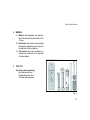
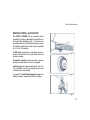
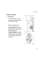
1
Redefin ing
mobi lity
worldwide.
ÓßÒËßÔÛ Ü× ËÍÑ Û ÓßÒËÌÛÒÆ×ÑÒÛ
ÑÉÒÛÎŽÍ ÓßÒËßÔ
ÓßÒËÛÔ ÜÛ ÓÑÜÛ ÜŽÛÓÐÔÑ× ÛÌ ÜŽÛÒÌÎÛÌ×ÛÒ
ÓßÒËßÔ ÜÛ ËÍÑ Ç ÓßÒÌÛÒ×Ó×ÛÒÌÑ
i ÝÑÒÑÍÝÛÌÛ Ôß
ÊÑÍÌÎß ÍÌßÎ
ÜÛÔËÈÛ ìÌ
i ÕÒÑÉ ÇÑËÎ
ÍÌßÎ ÜÛÔËÈÛ ìÍ
i ÐÑËÎ ÝÑÒÒß× ÌÎÛ
ÊÑÌÎÛ ÍÌßÎ
ÜÛÔËÈÛ ìÌ
i ÝÑÒÑÝÛ Î
ÊËÛÍ ÌÎß ÍÌß Î
ÜÛÔËÈÛ ìÌ
i ÝÑÓÛ ßÆ×ÑÒßÎÛ Ôß
ÊÑÍÌÎß ÍÌßÎ
ÜÛÔËÈÛ ìÌ
i ØÑÉ ÌÑ ÑÐ ÛÎßÌ Û
ÇÑËÎ Í Ìß Î
ÜÛÔËÈÛ ìÍ
i ÐÑËÎ ßÝÌ× ÑÒÒÛÎ
ÊÑÌÎÛ ÍÌßÎ
ÜÛÔËÈÛ ìÌ
i ÝMÓÑ ßÝÝ×ÑÒßÎ
ÊËÛÍ ÌÎß ÍÌß Î
ÜÛÔËÈÛ ìÌ
i ÝËÎß Û ÓßÒÌÛÒ×ÓÛÒÌÑ
ÜÛÔÔß ÊÑÍÌÎß
ÍÌßÎ ÜÛÔËÈÛ ìÌ
i ÝßÎÛ ßÒÜ
Óß× ÒÌÛÒßÒÝÛ
ÑÚ ÇÑËÎ
ÍÌßÎ ÜÛÔËÈÛ ìÍ
i ÍÑ×Ò ÛÌ ÛÒÌÎÛÌ× ÛÒ
ÜÛ ÊÑÌÎÛ ÍÌßÎ
ÜÛÔËÈÛ ìÌ
i ÝË×ÜßÜÑ Ç
ÓßÒÌÛ Ò× Ó×Û ÒÌ Ñ
ÜÛ ÊËÛÍ ÌÎß ÍÌßÎ
ÜÛÔËÈÛ ìÌ
Red ef in ing
mo bil ity
world wide .
ÑÉÒÛÎŽÍ ÓßÒËßÔ
i ÕÒÑÉ ÇÑË Î Í ÌßÎ ÜÛ ÔËÈÛ ì Í
i ØÑÉ ÌÑ ÑÐ Û ÎßÌÛ ÇÑËÎ Í ÌßÎ Ü ÛÔË ÈÛ ìÍ
i ÝßÎÛ ßÒÜ Óß× ÒÌ Û ÒßÒÝ Û ÑÚ ÇÑËÎ Í ÌßÎ ÜÛ ÔËÈÛ ì Í
IMPORTANT INFORMATION
1. Name: . . . . . . . . . . . . . . . . . . . . . . . . . . . . . . . . . . . .
3. YOUR VEHICLE
Address: . . . . . . . . . . . . . . . . . . . . . . . . . . . . . . . . . .
Model LML: STAR DELUXE 4 STROKE
..........................................
Colour: . . . . . . . . . . . . . . . . . . . . . . . . . . . . . . . . . . . .
..........................................
..........................................
Engine No.
Licence No.: . . . . . . . . . . . . . . . . . . . . . . . . . . . . . . . .
Chassis No.
2. YOUR DEALER. . . . . . . . . . . . . . . . . . . . . . . . . . . . .
Name: . . . . . . . . . . . . . . . . . . . . . . . . . . . . . . . . . . . .
Address:. . . . . . . . . . . . . . . . . . . . . . . . . . . . . . . . . .
Key No.: . . . . . . . . . . . . . . . . . . . . . . . . . . . . . . . . . . .
.........................................
Date of purchase: . . . . . . . . . . . . . . . . . . . . . . . . . . . . .
.........................................
Date of Registration:. . . . . . . . . . . . . . . . . . . . . . . . . .
.........................................
Tel. No.: . . . . . . . . . . . . . . . . . . . . . . . . . . . . . . . . . .
Registration No.: . . . . . . . . . . . . . . . . . . . . . . . . . . . . . .
Thank you for having chosen the STAR 4 Stroke as your new scooter.
The STAR scooter is manufactured by LML Limited – one of the motorcycle manufacturing company in rapid
expansion in India. A company that endeavours to redefine mobility everyday, the worldover by exceeding
customer expectations.
After years of studying the customer’
s needs, the company finally created the STAR 4 Stroke that promises
an incomparable ride.
It is equipped with a powerful 125/150cc four stroke engine that unleashes a phenomenal power.
Apart from offering an excellent performance and a comfortable ride, the Star will make everybody envious
thanks to its breathtaking design and its original colours that nobody can ignore.
This owner's manual has been specially designed to help you understand your scooter better. It is important
to read this manual to obtain the best performance from your Star. It will also help you to maintain it in the
best condition.
After reading this manual climb on board your new Star and discover international class mobility.
CONTENTS
DESCRIPTION
PAGE NO.
How to obtain the maximum performance
DESCRIPTION
PAGE NO.
Operating the vehicle
26
from your LML STAR 4 Stroke scooter
3
Running-in Instructions
29
Vehicle Identification
6
Care and Maintenance
30
Parts & Specifications
7
General specifications
9
Specifications - Auto start
13
Auto start Circuit Diagram
14
Technical Specifications
16
Control Functions
Locking System
Switches
Clutch
18
18
21
22
Gear
Brakes
Fuel supply
23
24
24
Cowls
Changing the tyres
Engine oil
Spark plug cleaning
Battery
Air Cleaner
Cleaning & Polishing
Maintenance while not in use
30
31
33
34
34
37
38
38
Recommended Lubricants
39
Maintenance by
LML authorised Technical Assistance Centre
40
Exhaust Emission Control
45
Wiring Circuit Diagram
46
2
Maximise the performance of your STAR 4S
HOW TO OBTAIN THE BE ST PERFORM ANCE FROM YOUR STAR 4
STROKE
Given below are some important features of your
scooter and some useful tips on how to maximize
the benefits it offers.
1. LML's fuel saver engine: This engine gives
the best fuel consumption at a driving speed of
35-45 kms/hr after running-in of 1000 kms.
The distance in kilometres can therefore vary
on the basis of the road conditions, the intensity
of traffic and driving habits and conditions, as
well as the respect for the periodical maintenance intervals.
Tips to stretch each litre of petrol even longer.
1.1 Change gears as per the required speed.
Try to maintain the speed of 35-45 kms/hr
to give you the best mileage.
1.2 Use clutch, brakes and full throttle only as
and when required.
1.3 Maintain the air pressure in the front tyre
at 1.4 bar and 1.6 bar in the rear tyre with
only the driver on board or 2.0 bar with
passenger.
3
Maximise the performance of your STAR 4S
2.
Safety devices of the STAR 4 STROKE:
Some tips for even safer driving.
The safety features inbuilt in your scooter
take away the worries from your driving. It is
a perfectly balanced scooter and its state of
the art braking system enables you to come
to an instant halt without skidding regardless
of the speed at which you are driving.
2.1. Always use a helmet while driving.
A powerful DC horn and indicators with a
buzzer enable you to negotiate busy and
noisy traffic conditions. In addition, the head
light retains its intensity even at low speed
that makes for safer night driving.
2.4. Never drive in neutral gear especially
when going down-hill or on a wet or slippery road.
2.2. Make yourself familiar with the driving
signs and regulations.
2.3. Drive at a speed at which you are in complete control of the scooter.
2.5. Use horn and indicators whenever required.
4
Maximise the performance of your STAR 4S
3.
The sensation of engine power of the STAR
4 STROKE: The engine power of your scooter
is not only the highest among all scooters but
also compares to some of the most popular
motorbikes in the same cubic capacity. You
can now surge ahead of other vehicles, either
from a stop position or while negotiating busy
traffic.
Some tips on how to keep power under control
3.1. Accelerate only to the extent you are in
complete control of the scooter.
3.2. Use its maximum power only when you
need to.
4.
An enjoyable ride that only the STAR 4
STROKE knows how to give: Your scooter
has been designed so as to enable you to sit
in a correct posture to avoid strain. Its comfortable and long seat, double acting suspension and strong shock absorbers better withstand uneven road conditions to give you
driving pleasure, unmatched by any scooter.
Some tips on how to enhance your driving
pleasure.
4.1. Maintain the correct posture.
4.2. Sit in a relaxed and natural manner, not
stiffly.
4.3. Reduce speed on uneven and bumpy
roads.
5
Vehicle Identification
VEHICLE IDENTIFICATION
The vehicle is identified by a number on the chassis
and another number on the engine.
The chassis identification number is stamped inside
the glove compartment on upper chassis as shown
in (Fig. 1).
Fig. 1
The engine number is stamped on the crank case
(Fig. 2).
Every STAR 4 STROKE has a spare set of keys.
An identification number is punched on metallic tag,
which is provided alongwith the key ring (Fig. 3).
Please keep your duplicate key carefully along with
the metallic tag.
Fig. 2
Fig. 3
6
Parts & Specifications
1.
Rearview mirror
7.
Silencer
13. Glove compartment
19. Driver’
s foot platform
2.
3.
Central stand
Seat
8.
9.
Kick starter
Rear brake pedal
14. Fuel cock lever
15. Choke control knob
20. Rear turn indicator
(LH side)
4.
5.
RH side cowl
Hook for bag
10. Front direction indicator
(right side)
16. LH side cowl
17. Front direction indicator
21. Rear mudguard
22. Tail light
6.
Rear turn indicator
11. Horn
(RH side)
12. 5 spoke wheel hub
(left side)
18. Spare wheel
7
Parts & Specifications
Fig. 7
Fig. 6
1.
2.
3.
4.
5.
6.
7.
Head light
Fairing edge trimming
STAR nameplate
Front turn indicator
Front mudguard
LML symbol
Fork cover
8.
9.
10.
11.
12.
13.
14.
LML nameplate
Grill
Crest
Central stand
Rear view mirror
Clutch lever
Glove compartment lock
15. Ignition-cum-steering lock
16. Instrument panel
17. Accelerator twistgrip
18. Front brake lever
19. Gearchange twistgrip
20. Indicator switch
21. Light switch – starter and horn
buttons
8
Parts & Specifications
GENERAL SPECIFICATIONS
1. ENGINE
1.1 Engine: 4 stroke, horizontal single cylinder
1.2 Ignition: Via an electronic starter device
(CDI) that feeds the live HT coil that generates the spark.
1.3 Lubrication: Wet sump forced pressure
splash through a pump.
1.4 Clutch: Multiplate, oil bath type. The unit
is cable operated by a lever located on
the left hand side of the handlebar and is
adjustable.
1.6 Cooling: Forced air provided by a centrifugal fan.
1.7 Mechanical starter: With kick starter
pedal located on the right hand side of
scooter. Push button only in auto start
model.
1.8 Electric starter: Pull in the clutch lever
and press the starter button.
1.5 Gear Box: Four speed forward drive with
constant mesh gears immersed in oil bath
are operated by the twist grip on the left
hand side of the handlebar which functions in conjunction with the clutch control
lever.
9
Parts & Specifications
2.
FUEL
2.1 Fuel supply: Gravity fed from fuel tank to
carburettor. Carburettor is a side draft
carburettor and is having a vertical moving throttle slide.
3.2 Handlebar: Light alloy casting with headlamp, instrument panel and indicator
lights. All transmission cables are concealed therein.
2.2 Fuel Gauge: In built with the speedometer indicates the quantity of petrol in the
petrol tank by virtue of a float unit located
inside the tank.
3.3 Steering column and suspension: The
steering column is pivoted on the front
wheel swinging hub. Front and rear suspensions are provided with helical spring
& hydraulic dampers.
2.3 Throttle Control: Acclerator controlled by
the twistgrip on the right side of the handlebars.
3.
CHASSIS
3.1 Chassis: Pressed steel sheet and strong
tubular structure. A pressed steel sheet
shell covers the tubular structure.
3.4 Rear view mirror: Stylish moulded rear
view mirrors on both sides of handlebar.
3.5 Security Lock: On the steering column
and operated by a key.
3.6 Glove Compartment: A sleek & spacious
glove compartment for keeping personal
belongings, secured with a lock.
3.7 Seat: Tip-up seat with a safety lock.
10
Parts & Specifications
4.
WHEELS
4.1 Wheels: Interchangeable and manufactured from pressed sheet steel with 3.50 x
10 tyres.
4.2 Rear brake: drum brake with expanding
brake-shoes activated by a foot pedal on
the right side of the foot platform.
4.3 Front brake: disc brake activated by a
manual lever positioned on the right side
of the handlebars.
5.
TOOL KIT
Tool kit in a pouch containing
Box Spanner with lever
Double sided screw driver
2 Double ended spanners
Fig. 8
11
Parts & Specifications
6.
ENGINE O IL: Quantit y of Engine oil in
the crank case is 850 ml. This is for
lubrication and c ooling of the Engine.
Alwa ys maintain Oil level as per the
marks prov ided on the level gauge /
dipstick as s hown in the figure for details of checking see page no. 33.
Upper le vel
Lower le vel
Fig. 9
Note :
ATak e car e that E ngin e O il leve l is
always m aint ained b etwee n the upper and lo wer level mar k o n th e oi l
leve l g auge / d ipstic k. Runn ing engi ne with in suf ficien t oil m ay caus e
ser iou s eng ine d amag e.
Fig. 10
12
Parts & Specifications
SPECIFICATIONS - AUTO START
The STAR 4 STROKE has an automatic starter
operated by a button underneath the light switch on
the right of the handlebars (Fig. 11) as well as an
optional method of kick starting the engine by using
the kickstart pedal. The auto start circuit is operated
by a 12 volt - 9 Ah battery.
A PRD relay (prevention of restarting device) is
provided to avoid use of the self starter when the
engine is running.
Fig. 11
A declutch switch has been provided to prevent
starting of scooter when the clutch is engaged.
An 8 Amp fuse (on spare wheel bracket, Fig. 12 &
13) is provided to avoid any damage due to short
circuiting in auto start system.
A powerful 12 volt-96 watt magneto charges the
battery through a regulator with a built in charger.
Fig. 12
Fig. 13
13
Parts & Specifications
14
Technical Specifications
TECHNICAL SPECIFICATIONS
Engine
Displacement
Bore x stroke
Compression ratio
Maximum power
Maximum torque
Fuel feed system
Fuel
Fuel tap
Spark plug
Clutch
Starter
Starter
Gearchange
Horizontal single cylinder four stroke, single overhead camshaft with two valves, cooled by forced air
125 cc / 150 cc
52.4 x 57.8 mm / 57.42 x 57.8 mm
9 ± 0.5 : 1
5.84 ± 0.25 kW at 6,000 rpm ± 200 rpm / 6.75 ± 0.25
kW at 6,250 rpm ± 200 rpm
9.15 Nm at 5,000 rpm / 11.54 Nm at 3,500 rpm
KEHIN PB Ø 18 carburettor
95 octane petrol
three-way:
Open (ON)
Closed (OFF)
Reserve (RES)
RG4HC (Champion)
C8EH9 (NGK)
UHR3CC (Bosch)
Multiplate oilbath type
Electronic (CDI)
Electric with kick start pedal
Manual, 4 speed gearbox with pinion always engaged
15
Technical Specifications
Lubrication
Silencer
Dimensions (L x W x H)
Seat height
Wheel base
Fuel tank capacity
Front suspension
Weight
Maximum load capacity
Wet sump
Catalysed with secondary air injection system
1,760 x 695 x 1,110 mm
820 mm
1,235 mm
5.5 litres including 1 litre reserve
Swing arm, hydraulic double-effect shock absorber
with helical spring
Engine crankcase functions partly as a swing arm
and hydraulic double-effect shock absorber with
helical spring
Assembled pressed sheet steel unit
3.50-10
Disc brake in stainless steel Ø 200 mm
Drum brake Ø 150 mm
Pressed sheet steel with rear tubular framed
structure covered by a sheet steel shell assembly.
121 kgs
275 kgs (2 persons with 10 kgs of luggage
Controls
Steering
Accelerator
Gears
Clutch
Front brake
Handle bar
Twist grip type on right hand side of the handle bar.
By hand on left hand side of the handle bar.
Lever operated on left hand side of the handle bar.
Lever operated by right hand.
Rear suspension
Front/rear wheels
Front/rear tyres
Front brake
Rear brake
Frame
16
Technical Specifications
Rear brake
Pedal operated by right foot.
Electricals
Generator system
Head lamp
Tail light bulb
Stop light bulb
Speedolight bulb
Turn signal light bulb
Tell tale lamp
Horn
Battery
Fuse
12 Volt 96 Watt.
12 Volt 35/35 Watt.
12 Volt 5 Watt.
12 Volt 10 Watt.
12 Volt 1.2 Watt x 2.
12 Volt 10 Watt.
12 Volt 1.2 Watt x 4.
12 Volt DC Horn fitted with AC to DC convertor
12 Volt 9 Ah.
8 Amp
17
Control Functions
CONTROL FUNCTIONS
1.
LOCKING SYSTEM
The STAR 4 STROKE has a single key to
block the steering, lock the glovebox and the
seat as well as start the ignition.
1.1 Steering lock-cum ignition switch.
Locking the Handlebar: First turn the handlebar to the extreme left and then turn the
key anti-clockwise to lock position. Pull out
the key after locking (Fig.14).
Un-locking the Handlebar: Insert the key
in ignition switch and turn it clockwise to
unlock the handlebar. To switch on the ignition turn the key further clockwise to "ON"
position (Fig. 15).
Fig. 14
Fig. 15
18
Control Functions
1.2 Glove compartment lock: To open the
lock, insert the key into the lock and rotate
anti-clockwise till the end and then press the
lock downwards. For closing, press the lid,
turn the key clockwise and then take out the
key (Fig. 16 & 17).
1.3 Seat Lock (Dual Seat): Insert the key, rotate it clockwise till the end then take it out.
Push the lock with thumb (Fig. 18) and lift
the saddle from the back (Fig. 19). Place the
saddle in its normal position & press it down.
To lock the saddle, follow the above procedure in reverse order.
Fig. 16
Fig. 17
Fig. 18
Fig. 19
19
Control Functions
INSTRUMENT PANEL
An elegantly designed instrument panel which contains the following:
1.
Fuel-Gauge
2.
Fuel level indicator needle
3.
Head light low beam indicator
4.
LH turn signal indicator
5.
Speed indicator needle
6.
Odometer
7.
RH Turn signal indicator
8.
Head light high beam indicator
Fig. 20
20
Control Functions
2.
CONTROL SWITCHES: Control switches are
located on the right and left hand sides of the
handlebar.
2.1
Right hand side of the handlebar (Fig.
21).
2.1.1 Headlight
l
l
l
2.1.3 Stop Light – Becomes operative when
foot brake pedal or hand brake lever is
pressed.
2.1.4 Horn – Press button (3)
2.1.5 Press the starter button (4) to electrically
start the engine but only after having
pulled in the clutch lever first.
Press bottom end of (1) to activate
the headlight.
Press top end of (2) for high beam or
bottom end of (2) for low beam.
Headlight is switched off if (1) is
pressed at top end.
High and low beam positions are indicated on the instrument panel.
2.1.2 Instrument Panel lights and tail lights.
Press bottom end of (1) for light. Press
top end of (1) to switch off light.
Fig. 21
21
Control Functions
2.2
Left hand side of the handlebar (Fig.
22).
2.2.1 Turn indicator switch: Press left hand
end of switch for turning left and right
hand end for turning right.
Left & right turn indicators are shown on
the instrument panel.
3.
CLUTCH AND GEARCHANGE CONTROLS:
Located on the left hand side of the handlebar,
consisting of clutch lever for engaging the
clutch and the gear twist for changing gears.
3.1 Clutch lever: Press the clutch lever towards the handlebar to disengage the
clutch. (Fig. 23).
Fig. 22
Fig. 23
22
Control Functions
3.2
Twist grip for gear change: There are 5
positions, one for neutral and the other four
for driving at different speeds as given below;
Gear
position
Speed band as
given below
1
Upto 10 Kms/hour
0
Neutral
2
10-20 kms/hour
3
20-35 kms/hour
4
35 kms/hour & above
Fig. 24
To change gear, press clutch lever and turn the
twist grip. (Fig. 24) to the required position.
4.
ACCELERATOR CONTROL: Located on the
right hand side of the handlebar. It is a twist
grip. For increasing acceleration rotate the
twist grip towards yourself. Do the reverse for
decreasing acceleration (Fig. 25).
Fig. 25
23
Control Functions
5.
BRAKES: There are two brakes one operated
by foot and the other operated by hand. Both
brakes should be applied simultaneously for
most effective braking.
5.1 Foot Brake: Operates on the rear wheel.
Press down brake pedal to apply the
brake. The distance in which the scooter
can be brought to a halt will depend on
the speed at which the vehicle is travelling and the user's driving habits. (Fig.
26).
Fig. 26
5.2 Hand Brake: Operates on the front
wheel. Press hand brake lever towards
the twist grip (Fig. 27).
6.
FUEL SUPPLY
6.1 The fuel tank is located under the seat
(Fig. 28) and is accessible only when the
seat is unlocked and lifted. For filling in
petrol unscrew the cap and close it after
refuelling.
Fig. 27
Fig. 28
24
Control Functions
6.2
Control of flow of petrol (Fig. 29) : There is
a fuel tap under the seat that has three
positions: (ON) for a regular flow of fuel,
(OFF) to stop the flow of fuel from the
tank to the engine and (RES) that must
be activated when on reserve.
If the vehicle stops on account of lack of
petrol, then turn the cock lever to (RES)
i.e. "RESERVE" position. There is one litre of petrol kept in reserve in your tank
for any emergency.
There is a fuel gauge in the instrument
panel for indicating the quantity of fuel in
the tank.
6.3 Choke control knob (Fig. 30): Located
below the fuel cock. To be used for starting the engine when it is cold. Pull the
choke knob out-wards for operation. Pull
out the choke control knob to operate it. It
must be pushed back in when the engine
has warmed up.
Caution: If the c hoke c ont r ol k nob is pulled
out a nd remai ns out , this would
c aus e an exc es siv e l evel of fuel in
the c ar bur ett or th at wo uld c aus e ir r egular run ning and elev ated f uel
c ons umpti on.
Fig. 29
Fig. 30
1. Choke control knob, 2. Fuel Cock lever,
3. Hook for Bag
7.
HOOK FOR BAG: There is a hook for hanging
a bag under the seat.
25
Operating the vehicle
OPERATING THE V EHICLE
Warning: Before driving your scooter make
yourself thoroughly familiar with all
operating controls and their functions.
1.
BEFORE STARTING THE ENGINE:
1.1 Check if tyres are properly inflated.
1.2 Check for correct play in the clutch lever
(Fig. 23) and make sure that it operates
properly.
1.3 Check that the brake pedal play is correctly adjusted.
1.4 Check that the accelerator control functions correctly and the play is within normal limits.
Fig. 31
A- Open fuel cock
B- Switch 'ON' ignition
C- Put gear in neutral position
D- Pull out the choke control knob (only when the engine is
cold)
E- Position the accelerator control at minimum.
F- De-clutch
G- Kick starter pedal
26
Operating the vehicle
2.
STARTING THE ENGINE (Fig. 31).
2.1 Turn fuel cock lever to "ON" position.
2.2 Turn 'ON' the ignition switch.
2.3 Put gear control in neutral position.
2.4 Pull out the the choke control knob only
when the engine is cold.
2.5 Bring the throttle to idling position.
2.6 If you are starting the engine for the first
time in the day, press the clutch lever
and, keeping it pressed, kick the starter
lever a couple of times.
2.7 Operate the kick pedal by pushing it down
with a kick for starting the engine. To start
the engine using the electric starter, press
the clutch lever and then press the starter
button.
2.8 When the engine is running normally,
press the choke knob back to its normal
position.
Caution:
3.
i.
Do not use electric starter for more than 5
seconds at a time. Release the push button
start switch for approximately ten seconds
before pressing it again. If the engine fails to
start after repeated attempts hold the throttle
1/8-1/4 open and push the button start
switch.
ii.
Before using the electric starter button,
ensure that the clutch lever has been
pressed.
DRIVING THE SCOOTER:
3.1 Remove the vehicle from stand, by pushing it forward.
3.2 Seat yourself on the scooter with feet on
the ground and hands on the handle bar.
3.3 With the engine running at idling speed,
press the clutch lever with the left hand
and rotate the gear twist grip to 1st gear
position.
3.4 Put the scooter in movement by gradually
releasing the clutch and simultaneously
turning the accelerator twistgrip.
27
Operating the vehicle
3.5 To change gear, rotate the accelerator
twistgrip back to zero, press the clutch
lever and turn the gearchange twistgrip
control and position it on the next upper
or lower gear.
3.6 Use indicator switch button for turning
and use horn whenever required.
4.
APPLICATION OF BRAKES:
4.1 Turn the accelerator twistgrip back to
zero.
4.2 Press the clutch lever and change the
gear to the neutral position.
4.3 Use foot pedal brake and hand brake
simultaneously for the most efficient braking.
28
Running-in-Instructions
ENGINE RUNNING-IN
Operation: The most important period in the life
of your scooter is its first 1000 kms. The engine is
brand new and different moving parts of the engine
need to be set to their correct operating tolerances.
This ensures a longer life for your vehicle. It is
therefore necessary to take some precautions so
as not to overload the engine.
1.
Keep to the following speed limits
1st Gear:
3.
Do not drive with half (partially engaged)
clutch. This will not only damage the clutch but
will also cause overheating of the engine.
4.
Allow a cooling off period of 5-10 minutes after
each hour of use.
5.
Ensure oil level in engine to recommended
level, by checking the level with the help of
dipstick.
0 to 10 kms/hr.
2nd Gear: 10 to 20 kms/hr.
3rd Gear: 20 to 35 kms/hr.
4th Gear:
35 kms/hr and above.
2. Avoid running the scooter on full accelerator
(throttle) for long periods. Vary the speed from
time to time.
29
Care and Maintenance
CARE AND MAINTENANCE
1.
REMOVAL AND REFITTING OF COWLS:
The right hand side cowl is to be removed for
checking of oil level and spark plug. The left hand
side cowl is to be removed for taking out or refitting
the spare wheel.
The levers for opening the cowls are placed under
the seat. To remove the cowls:
1.1 Lift the seat as explained on page 19.
1.2 Turn the cowl opening levers outwards
(Fig. 32).
1.3 Hold the body fairing with both hands and
remove the cover in an upwards and
backwards movement and remove it (Fig.
33 & 34).
1.4 Pull out the cowl by disengaging its rear
end. (Fig. 35).
1.5 Refit the cowl, by following above procedure in reverse.
Fig. 32
Fig. 33
Fig. 34
Fig. 35
30
Care and Maintenance
2.
CHANGING THE TYRES :
2.1
Removing and refixing the sparewheel
2.1.1 Remove the left hand side cowl as mentioned above.
2.1.2 The wheel is fixed by three nuts. Unscrew the nuts using the box spanner
from the tool kit, remove the three elastic
washers and remove the wheel (Fig.36).
2.1.3 For fixing the spare wheel follow the
above procedure in reverse order.
2.2
Changing of Front Wheel
2.2.1 Put the vehicle on its central stand.
2.2.2 Remove the five nuts that fix the wheel
to the wheel hub using the box spanner
from the tool kit (Fig. 37). While loosening the nuts, hold the wheel with one
hand.
2.2.3 Remove the spring washers and take
out the wheel from the brake drum.
2.2.4 For refitting, follow the above procedure
in reverse order.
2.3
Changing of Rear Wheel :
2.3.1 Put the vehicle on its central stand.
2.3.2 Remove side cowls as explained on
page 30.
Fig. 36
2.3.3 Remove the battery. Follow the instructions given on page 35 for removal and
installation of battery.
31
Care and Maintenance
2.3.4 Bring the fuel knob to "close" position.
Start the engine to exhaust petrol in the
carburettor as well as in the fuel line.
The engine will stop automatically when
the fuel is exhausted.
2.3.6 Lay the scooter gently on ground on its
right hand side with the handle bar
sleeve touching the ground at right angle.
2.3.7 Bring the vehicle in first gear and hold
the wheel with one hand. Remove the
five nuts securing the wheel to the brake
drum by using the box spanner (Fig. 38).
2.3.5 Remove the spare wheel as explained
on page 31.
2.3.8 Remove the spring washers and take
out the wheel from the brake drum.
2.3.9 For refitting, follow the above procedure
in reverse order.
Precaution:
Fig. 37
1.
Tighten all wheel securing nuts alternately and
progressively. Re-check if all nuts are tightened
properly.
2.
Get the tyre pressure checked to the recommended level at the nearest service station.
Fig. 38
32
Care and Maintenance
2.4 Tyre Rotation:
All three wheels of the STAR 4 STROKE are interchangeable. However, the air pressure in the tyre
will depend on whether it is fitted in the front or rear
position. To ensure even tyre tread wear, it is necessary to rotate the tyres and change the face of
the tyre (in relation to the wheel rim) after every
6000 kms. Follow the sequence for tyre rotation as
explained in fig. 39.
Fig. 39
3
CHECKING ENGINE OIL LEVEL AND
CLEANING SPARK PLUG
3.1 Park the vehicle on level surface.
3.1.1 Remove the right hand side cowl as directed on page 30.
3.2 Checking oil level:
3.2.1 For checking the oil level, unscrew dispstick as shown in fig. 40.
3.2.2 Clean dipstick by a dry cloth.
3.2.3 Immerse the oil level rod without screwing
it in.
Fig. 40
33
Care and Maintenance
3.2.4
3.2.5
3.2.6
3.2.7
3.2.8
3.3
3.3.1
3.3.2
3.3.3
3.3.4
3.3.5
3.3.6
3.3.7
Take out dip stick and check the level of oil,
as shown in fig. 9. Oil level should be above
lower level make and below upper level
mark.
If level is less add Engine Oil to maintain
correct level.
Refix the dipstick.
Wipe off any excess oil which may have
been spilled.
Refit the cowl.
Spark plug cleaning:
Remove the right hand cowl.
Disconnect the HT lead cable (Fig. 42).
Wipe & clean the area around the spark
plug.
Using the box spanner, unscrew the spark
plug (Fig. 43).
Clean out any excessive carbon deposit.
Refix the spark plug back to its position.
Refit the cowl.
If you have a feeler gauge you can check
the gap between the electrodes in the spark
plug. This gap should be 0.7-0.8 mm (fig.
41). To adjust the gap again, it is better to
go to an authorised LML assistance centre.
Fig. 42
Fig. 41
Fig. 43
4. BATTERY CHECKING
Battery requires regular and thorough
maintenance as advised below:
4.1.1
The level of electrolyte must always be
in between the upper and lower levels
marked on the battery. Normally a
constant level in the specified range is
maintained for about two months or
approximately 2000 kms (Fig. 44).
34
Care and Maintenance
4.1.2
The level of electrolyte should be
checked once in a month. In case of a
normal decrease (0,5 cm) put in distilled water only so as to reach the upper level indicated on the battery. If
there is a marked drop in the electrolyte level (1 cm or more) have the battery checked at an authorised LML assistance centre.
Caution:
1.
Bat ter y s hould be r emov ed i f the v ehicl e
is t o be w as hed ly ing on its s ide.
2.
Use only 8 Amp fuse to prevent serious damage
to the wiring harness & battery. Ignition switch
should be in "off" position while replacing fus
4.2 Removal and refitting the battery
4.2.1 Turn the ignition key to "off" position.
4.2.2 Remove the left hand side cowl as explained on page 30.
4.2.3 Remove the screw securing ground cable
(black) connected to the negative (–) battery terminal by using the end of the
screw driver from your tool kit. (Fig. 45)
4.2.4 Similarly follow the procedure for removing the red cable connected to the positive (+) battery terminal.
4.2.5 Remove the battery and the acid discharge tube.
4.2.6 Detach the fastener belt and take out the
battery.
Precaution:
Keep t he bat ter y and bl eeder tu be aw ay fr om
the v ehic le to av oi d any damag e t o the
pai nt ed s ur f ac e of t he s cooter due to l eak age
or s pi llage of batt er y elec tr oly te.
4.3
Installation:
4.3.1 Clean the battery box.
Fig. 44
35
Care and Maintenance
4.3.2 Clean the battery thoroughly from the
outside.
4.3.3 Put the battery in the battery box.
4.3.4 Connect the fastener belt first to the lower
hook, then hold the battery firmly with one
hand, stretch the belt and fasten it in the
upper hook. Re-check if the battery is fastened firmly (Fig. 46).
4.3.5 Re-fix battery bleeder tube and ensure
that it is routed properly through its clamp.
4.3.6 Fix the "Positive" (+) terminal first and
then the "Negative" (–) terminal.
4.3.8 Apply grease around the terminals to prevent corrosion.
4.3.9 Ensure, Protection cap provided on battery harness is fixed properly on positive
(+) terminal of battery.
Caution:
Al way s ens ur e that t he bl eeder t ube is not
c logged, c r imped or bent. The t ube mus t be
of an adequat e l engt h. R epl ace t he ble eder
tube in c ase it is not of cor r ec t length or it is
c logged, or bent .
4.3.7 Make sure the battery cable does not
touch any metallic surface during fitment.
Fig. 45
Fig. 46
36
Care and Maintenance
4.4
Storage of battery while not in use
4.4.1 Keep the battery fully charged.
4.4.2 Maintain electrolyte level at MAX./ "UPPER LEVEL"
4.4.3 Take battery out of the vehicle and store it
in a dry, cool place and at a constant
temperature.
4.4.4 Keep battery away from rain, dew, high
moisture and direct sunlight.
4.4.5 The battery should be charged once a
month when the vehicle is not in use.
For initial charging, the battery must be
charged at least for 7 hours.
Always go to the authorised LML assistance centre for battery maintenance and
charging the battery.
5. AIR CLEANER Air cleaner is fitted below the
fuel tank and requires cleaning during each periodical service and more frequently when riding in
dusty area's.
37
Care and Maintenance
6. CLEANING & POLISHING:
Frequent and thorough cleaning of your
scooter will further enhance its appearance and extend its life.
6.1
The scooter should be cleaned at ambient
temperature i.e., not immediately after
use or in hot sun.
6.2 Use a low pressure water hose for cleaning the vehicle.
6.3 Wipe it, clean and dry with soft cloth.
6.4 Do not use detergents or powders which
are likely to leave scratches on the surface.
6.5 For polishing, use normal car polish and
rub with soft cloth.
7.1 With the help of a pipe, syphon out the
petrol from the fuel tank.
7.2 Start the engine for some time and exhaust the petrol in the carburettor.
7.3 Remove the spark plug as explained on
page 34 and put a few drops of Engine
Oil in the spark plug hole. Press the kick
lever a couple of times. Refix the spark
plug.
7.4 Clean the vehicle thoroughly and apply
antirust grease on all unpainted metallic
parts.
7.5 Raise the wheels off the ground by placing wooden planks and deflate the tyres
so that they do not touch the floor.
7.6 Cover the scooter.
7.
CARE OF YOUR VEHICLE WHEN NOT
IN USE FOR LONG PERIODS
If you are not going to use your vehicle for
more than two months then you should
store it properly as per the following advices.
38
Recommended Lubricants
Recommended quantity of oil to be filled in Engine is 850 ml.
39
Maintenance by Authorised Service Dealer
PERIODICAL MAINTENANCE TO BE CARRIED OUT BY AN AUTHORISED LML ASSISTANCE CENTRE
Preventive Maintenance:
To obtain the best performance from your STAR 4 STROKE it is important to carry out periodical maintenance on your vehicle. The following table gives the suggested action for different items of maintenance and
their periodicity.
Code of suggested action is:
NR.
Item
1
Engine Oil
Check or maintenance
jobs
0 Km
Predelivery
Filling
R
500
Km
3000
Km
6000
Km
9000
Km
1200
0 Km
1500
0 Km
1800
0 Km
2100
0 Km
2400
0 Km
Replacement
S
Check level every 1000 Km and top up if required.
Replace every 3000 Km or every 1 year.
Replace every 3000 Km or every 1 year.
2
Engine Oil
Filter
Replacement
S
3
Engine Oil
Filter
Screen
Clean
P
P
P
P
P
P
P
P
P
2700
0 Km
3000
0 Km
P
P
40
Maintenance by Authorised Service Dealer
NR.
Item
Check or maintenance
jobs
4
Spark
Plug
Check/
Replacement
5
Air Filter
and its
elements
Clean/Lubricate
6
Fuel
Circuit
Pipes
Check/
Replacement
7
Fuel Filter
Check/
Replacement
8
Check
Emission
Level
9
10
0 Km
Predelivery
500
Km
3000
Km
6000
Km
9000
Km
1200
0 Km
1500
0 Km
1800
0 Km
2100
0 Km
2400
0 Km
2700
0 Km
3000
0 Km
C
C
C
C
S
C
C
C
S
C
C
P
P
P
S
P
P
P
S
P
P
C
C
C
C
S
C
C
C
S
C
C
C
C
S
C
S
C
S
C
S
C
S
Check/Adjust
C
C
C
C
C
C
C
C
C
C
C
Valves
Clearence
Check/Adjust
C
Nut Fixing
Head/
Cylinder
Check/
Tightened
C
C
C
C
C
C
C
C
C
C
C
C
C
C
C
C
C
C
41
Maintenance by Authorised Service Dealer
0 Km
Predelivery
NR.
Item
Check or maintenance
jobs
11
Chain &
Chain
Tensioner
Check/
Replacement
C
C
S
C
C
12
Chain
Guide
Check/
Replacement
C
C
C
C
C
13
Electrical
System
Check
C
C
C
C
C
C
C
C
C
C
C
C
14
Battery
Check
C
C
C
C
C
C
C
C
C
C
C
C
Check/
Replacement
C
C
C
C
C
C
C
C
C
C
C
C
15
Front
Brake
System
500
Km
3000
Km
6000
Km
9000
Km
1200
0 Km
1500
0 Km
1800
0 Km
2100
0 Km
2400
0 Km
2700
0 Km
3000
0 Km
Replace brake oil every 12000 Km or every 2 years
16
Rear
Brake
System
Check/Adjust/
Replacement
C
C
C
C
C
C
C
C
C
C
C
C
17
Clutch
Lever Play
Check/Adjust
C
C
C
C
C
C
C
C
C
C
C
C
42
Maintenance by Authorised Service Dealer
NR.
Item
Check or maintenance
jobs
0 Km
Predelivery
500
Km
3000
Km
6000
Km
9000
Km
1200
0 Km
1500
0 Km
1800
0 Km
2100
0 Km
2400
0 Km
2700
0 Km
3000
0 Km
18
Accelerator Command
Check/Adjust
C
C
C
C
C
C
C
C
C
C
C
C
19
Steering
Column
Rings
Check/Adjust
C
C
C
C
C
C
C
C
C
C
C
C
20
Security
Tightened
Nuts,
Bolts and
Screw
Check/
Tightened
C
C
C
C
C
C
C
C
C
C
C
C
21
Central
Stand
Check
C
C
C
C
C
C
C
C
C
C
C
C
Check
C
C
C
C
C
C
C
C
C
C
C
C
Check/
Clean
C
C
C
C
C
C
C
C
C
C
C
C
22
23
Oil Pump
Functioning
Clean
Crank
Case
Breather
Tube
43
Maintenance by Authorised Service Dealer
NR.
Item
24
Rear/Front
Damper
25
Wheels/
Tires
Check or maintenance
jobs
0 Km
Predelivery
500
Km
3000
Km
6000
Km
9000
Km
1200
0 Km
1500
0 Km
1800
0 Km
2100
0 Km
2400
0 Km
2700
0 Km
3000
0 Km
Check
C
C
C
C
C
C
C
C
C
C
C
C
Check/Replaceme
nt
C
C
C
C
C
C
C
C
C
C
C
C
Tyre rotation every 6000 Km
C: Check/Adjust
P: Clean/Lubricate
S: Replacement
R: Filling
44
EXHAUST EMISSION CONTROL
In accordance with the Central Motor Vehicle Rules,
LML range of scooters manufactured by LML Limited meet emission standards prior to despatch from
factory.
Normally simple carburettor adjustment will help to
control CO level in exhaust gases. However, it is
necessary to check Carbon Monoxide (CO) level in
exhaust gases.
Following are some tips to control CO level in exhaust gases:
3. Clean and adjust carburettor properly.
Adjust the air mixture screw to ½ to 1½ threads
anti-clockwise from fully to closed position and
thereafter set idling screw 1000 to 1300 RPM.
4. Check the compression pressure and ensure
that it is within limits. Check ignition timing and
reset as recommended.
5. Check and adjust spark plug gap.
1. Use only recommended spark plug.
2. Clean the air filter and replace if required.
45
Care and Maintenance
SECONDARY AIR SUPPLY SYSTEM
Secondary air supply system
Removal /Installation
(A) Remove hex bolts (Fig . 47) of mounting
bracket secondary air system.
Bolt
(B) Disconnect tube to Air cleaner box (X), intake
manifold (Y) by removal of spring clips.
(C) Disconnect tube (Z) to Silencer by removal of
hose clamp.
Fig. 47
(D) For cleaning, blow air through pipe X. Y. Z.
(E) Check tubes for leakage replace if necessary.
Fig. 48
47
The descriptions and illustrations in this booklet are not to be taken as binding on the manufacturer. The essential features of the model described and illustrated herein remaining unaltered, LML Limited, reserves the
right to carry out at any moment, without being obliged to bring this booklet up-to-date, modifications to the
machine, its parts, or accessories, that the company deems to be convenient for improvement purposes or of
what may be required for manufacturing or commercial purposes.
Redefining
mobility
wor ldwide.
C-10, Panki Industrial Estate, Site ll, Kanpur - 208022, INDIA.
: 91-512-2691391, 6660301
: [email protected]
: 91-512-2691381, 6660300