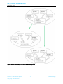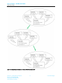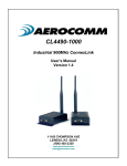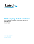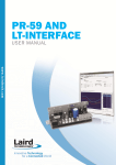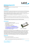
1
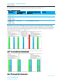
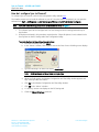
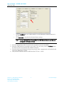
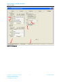
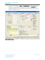
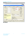
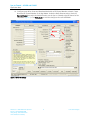
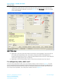
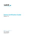
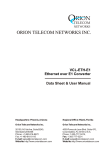
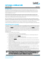
SYNC TO CHANNEL – AC4490 AND CL4490
Application Note
April 2013
INTRODUCTION
Laird Wireless uses frequency hopping protocol with a fixed pseudo-random hopping sequence on our
transceivers. This protocol yields superior interference rejection and multipath immunity. The server radio
sends timing beacons out on a regular interval and the clients hear these beacons and synchronize their
frequency hopping to the server.
Though servers cannot send packets to each other, they can hear the timing beacons sent out by other
servers. Normally, the servers ignore these beacons. However, when Sync to Channel is enabled, and a
specific server is designated as the synchronization master, the other servers listen for the beacons from the
master server and then synchronize their hop timing to that server.
Why is this important? If two servers (and their clients) are operating in the same area and their frequency
hopping is not synchronized to each other, they might try to occupy the same frequency at the same time. In
severe cases, they could interfere with each other on every frequency, causing very sluggish communications.
To avoid interference, collocated servers can use Sync to Channel. Sync to Channel synchronizes the
frequency hop timing between these servers so that they never occupy the same frequency at the same time.
CONFIGURING SYNC TO CHANNEL
To use Sync to Channel, you should designate one server (preferably the most centrally located server) as the
“Hop Master.” This server should be programmed to a numerically low RF Channel Number and should have
Sync-to-Channel disabled. All other servers in the area should have Sync to Channel enabled and have their
Sync-Channel set to the RF Channel Number of the server chosen as the Hop Master. Preferably, if a server is
outside of the range of the Hop Master server it can have its Sync Channel set to the RF Channel Number of
another server (with a lower RF Channel Number than its own) that is in range of, and synchronized to, the
Hop Master server.
The following rules apply to Sync-to-Channel:
1. One server should perform the function of Hop Master.
2. The Hop Master server should have its RF Channel Number set to a numerically low value and
should have Sync to Channel disabled.
3. It is preferable to centrally locate the Hop Master server.
4. All Servers in the collocated system (those synchronized to the Hop Master server) should have
Sync to Channel enabled.
5. All servers in the collocated system should have their Sync Channel set to a value lower than their
RF Channel Number.
6. All servers, including the Hop Master server, should have their RF Channel Numbers separated by a
minimum of 4-5 Channels (i.e. Server 1, Hop Master = RF Ch 16, Server 2 = RF Ch 21, Server 3 =
RF Ch 26…) to avoid inter-channel interference between the radios as they hop through their
pseudo-random hopping sequence.
7. If the servers to be synchronized are in range of the Hop Master server, it is preferable to set their
Sync Channel to the RF Channel Number of the Hop Master server.
8. If some of the servers to be synchronized are outside of the range of the Hop Master server, set
their Sync Channel to the RF Channel Number of a server (with a lower RF Channel Number than
its own) that is in range of, and synchronized to, the Hop Master server.
Note:
All servers with Sync-to-Channel enabled depend on the server designated as Hop Master. If the
Hop Master is not powered on and in range, the Sync-to-Channel servers will not synchronize,
their LINK LED will not illuminate, and their networks will not communicate.
Americas: +1-800-492-2320 Option 2
Europe: +44-1628-858-940
Hong Kong: +852 2923 0610
www.lairdtech.com/ramp
1
Laird Technologies
Sync to Channel – AC4490 and CL4490
Application Note
All collocated servers must be programmed to the same channel set, as shown in Table 1.
Table 1: RF Channels for CL4490
Channel Set
0 (CL4490 - 1x1
CL4490 - 200)
1 (CL4490 - 1x1
CL4490 - 200
CL4490 - 1000)
2 (CL4490 - 1x1
CL4490 - 200
CL4490 - 1000)
RF Channel Number
Range (0x40)
0x00 - 0x0F
Frequency Details & Regulatory
Requirements
902 - 915 MHz (26 hop bins)
Countries
0x10 - 0x2F
902 - 928 MHz (50 hop bins)
US / Canada
0x30 - 0x37
915 - 928 MHz (22 hop bins)
Australia (-1x1/-200/-1000)
US / Canada
What happens if you don’t enable Sync to Channel and you have collocated servers? There are good odds
that you will see a decrease in throughput due to the systems trying to occupy the same frequency at the
same time. In severe cases, you could lose communications all together depending on how much bandwidth
your system requires. Due to crystal differences between the servers, you may see intermittent interference.
Sync to Channel is pictured in Figure 1 and Figure 2.
Figure 1: Two servers without Sync to Channel enabled
Figure 2: Two servers with Sync to Channel enabled
Americas: +1-800-492-2320 Option2
Europe: +44-1628-858-940
Hong Kong: +852 2923 0610
www.lairdtech.com/ramp
2
Laird Technologies
Sync to Channel – AC4490 and CL4490
Application Note
How do I configure Sync to Channel?
To configure Sync to Channel, use the Laird Configuration Utility available here.
The installer prompts you to install the software on your PC. Once the install is completed, you can open the
software from Start -> All Programs -> Laird Technologies Wireless -> Laird Technologies Config.exe.
Note:
Items 2-6 in the following list correlate to the numbered items in Figure 3.
1. The software opens to the Configure tab. You must change to the PC Settings tab at the top of
the window.
2. RF Options mentioned in this procedure require that the "Show All Options" box is selected in the
Security Pane on the PC Settings tab of the Configuration Utility.
To enable the Security Pane follow these directions:
a. From the PC Settings tab, click About.
b. In the “About” window, click anywhere next to the lines of text. A blinking cursor displays.
\
c.
Type the following in all lower case letters: showframe!
Note:
Nothing displays on the window when you type.
d. When you finish typing, the Wireless Configuration and Test Utility window appears and
says “Security Frame now visible”.
e.
Click OK in the Wireless Configuration and Test Utility window.
f.
Click OK in the “About” window.
g. A “Security” section now displays on the PC Settings tab.
h. Check the Show All Options check box.
Americas: +1-800-492-2320 Option2
Europe: +44-1628-858-940
Hong Kong: +852 2923 0610
www.lairdtech.com/ramp
3
Laird Technologies
Sync to Channel – AC4490 and CL4490
Application Note
i.
Click the Configure tab. The “Radio Features” list now displays the advanced features in
the right column.
j.
Click Read Radio to populate the advanced feature settings.
Note:
For more detailed information on how to enable the security pane, see the Laird
Configuration Utility User Manual.
3. Select the appropriate product from the Product drop-down menu (Connex4490).
4. Select the COM Port that is connected to your radio. If you are unsure, press the Find Ports button
and the drop down list populates with available COM ports.
5. Select the baud rate that matches the baud rate that the radio is programmed to (the default baud
rate for the 4490 family is 57600.
6. Verify that the COM Port selected is OPEN and that CTS Port 1 is LOW.
Americas: +1-800-492-2320 Option2
Europe: +44-1628-858-940
Hong Kong: +852 2923 0610
www.lairdtech.com/ramp
4
Laird Technologies
Sync to Channel – AC4490 and CL4490
Application Note
Figure 3: PC Settings tab
Americas: +1-800-492-2320 Option2
Europe: +44-1628-858-940
Hong Kong: +852 2923 0610
www.lairdtech.com/ramp
5
Laird Technologies
Sync to Channel – AC4490 and CL4490
Application Note
7. Go to the Configure tab and click the Read Radio button at the bottom right of the screen. A
message stating “Read Successful” should appear after a successful read (Figure 4).
Figure 4: Configure tab - Read Successful
Americas: +1-800-492-2320 Option2
Europe: +44-1628-858-940
Hong Kong: +852 2923 0610
www.lairdtech.com/ramp
6
Laird Technologies
Sync to Channel – AC4490 and CL4490
Application Note
8. To configure the Hop Master, select Server and Broadcast Mode. Make note of the RF Channel
Number (Figure 5). Once the appropriate changes have been made, click Write Radio. A Write
Successful prompt appears after a successful write. Note that the values are shown using
hexadecimal representation; you may change this to decimal notation by double-clicking on the
word “Hex” (it changes to “Dec”).
Figure 5: Hop Master settings
Americas: +1-800-492-2320 Option2
Europe: +44-1628-858-940
Hong Kong: +852 2923 0610
www.lairdtech.com/ramp
7
Laird Technologies
Sync to Channel – AC4490 and CL4490
Application Note
9. Configure all radios that will communicate with the Hop Master server as Client and Auto
Destination with the same RF Channel Number as the Hop Master server. Then click Write Radio.
Figure 6: Client settings
Americas: +1-800-492-2320 Option2
Europe: +44-1628-858-940
Hong Kong: +852 2923 0610
www.lairdtech.com/ramp
8
Laird Technologies
Sync to Channel – AC4490 and CL4490
Application Note
10. Configure server #2 as Server and Broadcast Mode with an RF Channel Number at least 4-5 steps
above the RF Channel Number of the Hop Master. Under the Radio Features section, check the
Sync to Channel box and in the Radio RF section, set the Sync to Channel to the RF channel of the
Hop Master (Figure 7). Click Write Radio to write the changes to the radio’s EEPROM.
Figure 7: Server #2 settings
Americas: +1-800-492-2320 Option2
Europe: +44-1628-858-940
Hong Kong: +852 2923 0610
www.lairdtech.com/ramp
9
Laird Technologies
Sync to Channel – AC4490 and CL4490
Application Note
11. Configure the radios that will communicate with server #2 as Client and Auto Destination and
with the same RF Channel Number as server #2 (Figure 8). Click Write Radio to write the changes
to the radios EEPROM.
Figure 8: Client settings
12. Repeat Step 10 for each server that needs to synchronize to the Hop Master; if the server will not
be in range of the Hop Master server, set its Sync to Channel to the RF Channel Number of
another synchronized server that is in range of the Hop Master (make sure the RF Channel Number
of the server is higher than the Sync to Channel).
13. Repeat Step 12 for all clients that you wish to communicate with each server from Step 12.
I’ve configured my radios, what’s next?
Once you have configured all radios, set up your network similarly to the one shown in Figure 9. The main
server or Hop Master must be powered on anytime that the other servers are connected to enable them to
synchronize and communicate with their clients. If a centralized network does not work and all servers are
not in range of the Hop Master, use a daisy chain network as shown in Figure 10.
Americas: +1-800-492-2320 Option2
Europe: +44-1628-858-940
Hong Kong: +852 2923 0610
www.lairdtech.com/ramp
10
Laird Technologies
Sync to Channel – AC4490 and CL4490
Application Note
Figure 9: Sample Centralized Sync to Channel Network configuration
Americas: +1-800-492-2320 Option2
Europe: +44-1628-858-940
Hong Kong: +852 2923 0610
www.lairdtech.com/ramp
11
Laird Technologies
Sync to Channel – AC4490 and CL4490
Application Note
Figure 10: Sample Daisy Chain Sync to Channel Network configuration
Americas: +1-800-492-2320 Option2
Europe: +44-1628-858-940
Hong Kong: +852 2923 0610
www.lairdtech.com/ramp
12
Laird Technologies