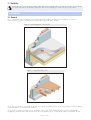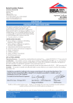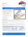
1
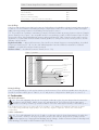
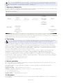
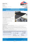
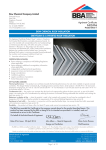
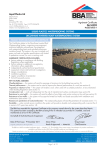
APPROVAL INSPECTION TESTING CERTIFICATION Celotex Limited Lady Lane Industrial Estate Hadleigh Ipswich Suffolk IP7 6BA Tel: 01473 822093 Fax: 01473 820880 TECHNICAL APPROVALS FOR CONSTRUCTION Agrément Certificate 95/3197 e-mail: [email protected] website: www.celotex.co.uk Product Sheet 2 CELOTEX INSULATION CELOTEX RANGE OF PIR INSULATION BOARDS FOR FLOOR INSULATION PRODUCT SCOPE AND SUMMARY OF CERTIFICATE This Certificate relates to the Celotex Range of PIR Insulation Boards for Floor Insulation, comprising rigid polyisocyanurate foam boards with low emissivity aluminium foil facings on both sides, for use as floor insulation. AGRÉMENT CERTIFICATION INCLUDES: • factors relating to compliance with Building Regulations where applicable • factors relating to additional non-regulatory information where applicable • independently verified technical specification • assessment criteria and technical investigations • design considerations • installation guidance • regular surveillance of production • formal three-yearly review. KEY FACTORS ASSESSED Thermal performance — the manufacturer’s declared thermal conductivity (90/90 value) of the insulation component of the products, as declared by the Certificate holder, is 0.022 W·m–1·K–1 (see section 5). Condensation — the foil facings have a water vapour resistance exceeding 70 MN·s·g–1 and the insulation core has a water vapour resistivity of 300 MN·s·g–1m–1 and, therefore, will provide a significant resistance to water vapour transmission (see section 6). Behaviour in relation to fire — the products will be contained within the floor by the overlay until the overlay itself is destroyed (see section 7). Floor loading — the products, covered with a screed overlay or concrete slab can support design loadings for selfcontained dwelling units as defined in BS 6399-1 : 1996 without undue compression deflection (see section 8). Durability — the products, when installed with the overlays specified, will remain effective as an insulating material for the life of the building in which it is incorporated (see section 11). The BBA has awarded this Agrément Certificate to the company named above for the products described herein. These products have been assessed by the BBA as being fit for their intended use provided they are installed, used and maintained as set out in this Certificate. On behalf of the British Board of Agrément Date of Second issue: 12 October 2010 Chris Hunt Greg Cooper Originally certificated on 31 March 1996 Head of Approvals — Physics Chief Executive Certificate amended on 3 November 2010 with updated information in the Thermal performance section. The BBA is a UKAS accredited certification body — Number 113. The schedule of the current scope of accreditation for product certification is available in pdf format via the UKAS link on the BBA website at www.bbacerts.co.uk Readers are advised to check the validity and latest issue number of this Agrément Certificate by either referring to the BBA website or contacting the BBA direct. British Board of Agrément Bucknalls Lane Garston, Watford Herts WD25 9BA ©2010 Page 1 of 12 tel: 01923 665300 fax: 01923 665301 e-mail: [email protected] website: www.bbacerts.co.uk Regulations In the opinion of the BBA, the Celotex Range of PIR Insulation Boards for Floor Insulation, if used in accordance with the provisions of this Certificate, will meet or contribute to meeting the relevant requirements of the following Building Regulations: The Building Regulations 2010 (England and Wales) Requirement: A1 Loading Comment: Requirement: C2(a)(c) Resistance to moisture Comment: Requirement: L1(a)(i) Conservation of fuel and power Floors incorporating the products can meet this Requirement. See section 8.1 of this Certificate. Floors incorporating the products can meet this Requirement. See sections 6.1 and 6.3 of this Certificate. Comment: The products can contribute to a building to meet its Target Emission Rate. See sections 5.3 to 5.6 of this Certificate. Requirement: Regulation 7 Materials and workmanship Comment: The products are acceptable. See section 11 and the Installation part of this Certificate. The Building (Scotland) Regulations 2004 (as amended) Regulation: 8(1) Regulation: Standard: 9 1.1(a)(b) 3.15 6.1(b) 6.2 Carbon dioxide emissions Building insulation envelope The products can contribute to satisfying these Standards, with reference to clauses, or parts of, 6.1.2(1), 6.1.3(2), 6.1.6(1), 6.2.1(1), 6.2.3(1), 6.2.6(2) and 6.2.9(1)(2) to 6.2.12(1)(2). See sections 5.3 to 5.6 of this Certificate. Comment: Regulation: Condensation Floors incorporating the products can satisfy this Standard, with reference to clauses 3.15.1(1), 3.15.4(1). See sections 6.1 and 6.4 of this Certificate. Comment: Standard: Standard: Building standards — construction Structure Floors incorporating the products can satisfy this Standard, with reference to clause 1.1.1(1). See section 8.1 of this Certificate. Comment: Standard: Fitness and durability of materials and workmanship The products can contribute to a construction satisfying this Regulation. See section 11 and the Installation part of this Certificate. Comment: 12 Building standards — conversions All comments given for the products under Regulation 9, also apply to this Regulation, with reference to clause 0.12.1(1) and Schedule 6(1). Comment: (1) Technical Handbook (Domestic). (2) Technical Handbook (Non-Domestic). The Building Regulations (Northern Ireland) 2000 (as amended) Regulation: B2 Fitness of materials and workmanship Comment: Regulation: C5 Condensation Comment: Regulation: D1 Stability Comment: Regulation: F2(a)(i) Conservation measures Comment: Regulation: F3(2) Target carbon dioxide Emissions Rate Comment: The products are acceptable. See section 11 and the Installation of this Certificate. Floors incorporating the products can meet this Regulation. See section 6.1 of this Certificate. Floors incorporating the products can meet this Regulation. See section 8.1 of this Certificate. See sections 5.3 to 5.6 of this Certificate. The products can contribute to a building satisfying its Target Emission Rate. See sections 5.3 to 5.6 of this Certificate. Construction (Design and Management) Regulations 2007 Construction (Design and Management) Regulations (Northern Ireland) 2007 In the opinion of the BBA, there is no information in this Certificate which relates to the obligations of the client, CDM co-ordinator, designer and contractors under these Regulations. Page 2 of 12 Non-regulatory Information NHBC Standards 2010 NHBC accepts the use of the Celotex Range of PIR Insulation Boards for Floor Insulation, when installed and used in accordance with this Certificate, in relation to NHBC Standards, Chapter 5.1 Substructure and ground bearing floors. General This Certificate relates to the Celotex Range of PIR Insulation Boards for Floor Insulation for use on ground-supported or suspended concrete or timber floors and also for use with exposed or semi-exposed intermediate concrete or timber floors of new or existing floors of dwellings or buildings of similar occupancy, type and condition. Technical Specification 1 Description The Celotex Range of PIR Insulation Boards for Floor Insulation comprises Celotex TB4000, GA4000, XR4000, FF4000, GX4000 and FR4000, rigid polyisocyanurate foam board with low emissivity aluminium foil facings on both sides. These products are available in the dimensions given in Table 1. Table 1 Nominal dimensions Size (mm) Product Thickness (mm) TB4000 1200 x 2400 12, 20, 25, 30, 35, 40 and 45 GA4000 1200 x 2400 50, 55, 60, 65, 70, 75, 80, 85, 90, 95 and 100 XR4000 1200 x 2400 110, 120, 130, 140, 150, 165 and 200 FF4000 1200 x 2400 50, 70, 75, 85, 90, 100 and 125 GX4000 1200 x 600 FR4000 1200 x 2400 20–200 25, 50, 60, 70, 75, 80, 90, 100, 110, 120, 130, 140 and 150 2 Delivery and site handling 2.1 The boards are delivered to site in packs. Each pack contains a label bearing the manufacturer’s name, board dimensions and the BBA identification mark incorporating the number of this Certificate. 2.2 The boards must be protected from prolonged exposure to sunlight and should be stored either under cover or protected with opaque polythene sheeting. Where possible, packs should be stored inside. If stored outside, the boards should be stacked flat and raised above ground level, and not in contact with ground moisture. 2.3 Care must be exercised in handling individual boards to avoid crushing the edges or corners. 2.4 The boards must not be exposed to open flame or other ignition sources. Assessment and Technical Investigations The following is a summary of the assessment and technical investigations carried out on the Celotex Range of PIR Insulation Boards for Floor Insulation. Design Considerations 3 General 3.1 The Celotex Range of PIR Insulation Boards for Floor Insulation is effective in reducing the thermal transmittance (U value) of new or existing concrete or timber floors. 3.2 Ground-supported floors incorporating the boards must include a suitable damp-proof membrane, laid in accordance with the relevant sections of CP 102 : 1973 , BS 8102 : 1990 and/or BS 8215 : 1991 (see section 9). 3.3 Suspended concrete or timber ground floors incorporating the boards must include suitable ventilation of the subfloor void or a damp-proof membrane (see section 9). 3.4 The overlay to the boards should be one of: • a floor screed, laid in accordance with the relevant clauses of BS 8204-1 : 2003 and BS 8204-2 : 2003 • a wood-based floor, eg tongue-and-groove plywood 16 mm thick (minimum) to BS EN 636 : 2003, flooring grade particle board (Types P4 to P7) to BS EN 312 : 2003 or oriented strand board of types OSB/2 to OSB/4 to BS EN 300 : 1997, 18 mm thick (minimum), installed in accordance with DD ENV 12872 : 2000 • a concrete slab. Page 3 of 12 3.5 If present, mould or fungal growth should be treated prior to the application of the products. 4 Practicability of installation The products are designed to be installed by a competent general builder, or a contractor, experienced with this type of product. 5 Thermal performance 5.1 Calculations of the thermal transmittance (U value) of specific floor constructions should be carried out in accordance with BS EN ISO 6946 : 2007 and BRE Report (BR 443 : 2006) Conventions for U-value calculations, using the declared thermal conductivity (90/90 value) of 0.022 W·m–1·K–1 and an emissivity of the outer layer of 0.05. 5.2 The U value of a completed floor will depend on the selected insulation thickness, the perimeter/area ratio and the floor type. Calculated U values for example constructions are given in Table 2. Table 2 Example floor U values Insulation thickness Floor type Perimeter/ area ratio 75 mm (W·m–2·K–1) 100 mm (W·m–2·K–1) 150 mm (W·m–2·K–1) 200 mm (W·m–2·K–1) Slab on ground support 0.2 0.4 0.6 0.8 1.0 0.15 0.19 0.21 0.22 0.23 0.13 0.15 0.17 0.17 0.18 0.10 0.11 0.12 0.13 0.13 0.08 0.09 0.10 0.10 0.10 Suspended timber floor 0.2 0.4 0.6 0.8 1.0 0.20 0.25 0.27 0.28 0.29 0.18 0.21 0.22 0.23 0.24 0.14 0.16 0.17 0.17 0.18 0.12 0.13 0.13 0.14 0.14 5.3 When considering insulation requirements, designers should refer to the detailed guidance contained in the documents supporting the national Building Regulations. The U values shown in Table 2 indicate that the product can enable, or contribute to enable, a floor to achieve typical design U values referred to in those supporting documents (see Tables 3, 4 and 5). Table 3 Mean design floor U values — England and Wales (1) Construction U value (W·m–2·K–1) Notional non-domestic building 0.22 Existing building — new or replaced floor 0.22 Dwelling new-build limit 0.25 Notional dwelling 0.25 Non-domestic new-build limit 0.25 Existing building — renovated or retained floor 0.25 (1) Flexible approaches on existing buildings are given in the Approved Documents. Table 4 Mean design floor U values — Scotland (1) Construction U value (W·m–2·K–1) Notional dwelling 0.15 New dwelling simplified method 0.15 Conversion unheated building (into dwellings) 0.15 Extension to dwelling 0.15 Alterations and reconstructions to a dwelling 0.18 Stand-alone building <50 m2 to a dwelling 0.18 New dwelling limit 0.20 New non-dwellings limit for shell and fit out 0.20 Conversion of unheated building 0.20 Non-domestic extension, alterations and reconstructions 0.20 New non-domestic limit 0.22 Notional non-dwelling 0.25 Conversion of heated building 0.25 (1) Flexible approaches on existing buildings are given in the Technical Handbooks. Page 4 of 12 Table 5 Mean design floor U values — Northern Ireland (1) Construction U value (W·m–2·K–1) Existing building — new floors 0.22 Notional dwelling 0.25 Building new-build limit 0.25 Notional non-domestic building 0.25 Existing building — replaced, renovated or retained floor 0.25 (1) Flexible approaches on existing buildings are given in the Technical Booklets. New buildings 5.4 Floors with U values lower than (or the same as, for dwellings in Scotland) the relevant ‘notional’ value specified in Table 4 or 5 will contribute to a building meeting its Target Emission Rate. Floors with higher U values will require additional energy saving measures in the building envelope and/or services. 5.5 The products can contribute to maintaining continuity of thermal insulation at junctions between elements. Example junction details shown in Figure 1 are acceptable and the corresponding psi values in BRE Information Paper IP1/06 Assessing the effects of thermal bridging at junctions and around openings, Table 3 may be used in carbon emission calculations in Scotland and Northern Ireland. Detailed guidance for other junctions and on limiting heat loss and air infiltration can be found in: England and Wales — Approved Documents to Part L and for new thermal elements to existing buildings, Accredited Construction Details (version 1.0). See also SAP 2009 Appendix K and the iSBEM User Manual for new-build. Scotland — Accredited Construction Details (Scotland) Northern Ireland — Accredited Construction Details (version 1.0). Figure 1 Junctions Celotex PIR perimeter upstand insulation screed polythene separating layer Celotex PIR insulation dpm slab Existing buildings 5.6 For existing buildings, in work such as extensions and conversions, floors will be acceptable where they do not exceed the relevant U value given in Tables 3, 4 or 5 and junctions comply with the details given in section 5.5. 6 Condensation Interstitial condensation 6.1 Floors will adequately limit the risk of interstitial condensation when they are designed and constructed in accordance with BS 5250 : 2002, Section 8.5 and Appendix D. The foil facings have a water vapour resistance exceeding 70 MN·s·g–1 and the insulation core has a water vapour resistivity of 300 MN·s·g–1m–1. 6.2 A vapour control layer in the warm side of the insulation, or the damp-proof membrane [acting as a vapour control layer (VCL)] situated (as appropriate) in the warm side, might be required to limit the risk of interstitial condensation. Surface condensation 6.3 Floors will adequately limit the risk of surface condensation when the thermal transmittance (U value) does not exceed 0.7 W·m–2·K–1 at any point, and the junctions with walls are designed in accordance with the relevant requirements of Limiting thermal bridging and air leakage : Robust construction details for dwellings and similar buildings, TSO 2002 or BRE Information Paper IP 01/06. Page 5 of 12 6.4 Floors will adequately limit the risk of surface condensation when the thermal transmittance (U value) does not exceed 1.2 W·m–2·K–1 at any point. Guidance may be obtained from BS 5250 : 2002, Section 8, and BRE Report (BR 262 : 2002) Thermal insulation : avoiding risks. 7 Behaviour in relation to fire 7.1 The products do not prejudice the fire resistance properties of the floor provided they are used in accordance with BS 6203 : 2003. The boards may be classified as shown in Table 6. Table 6 Fire classification TB4000 GA4000 XR4000 FF4000 GX4000 FR4000 Class 1 to BS 476-7 (20–90mm) Class 1 to BS 476-7 (50–90 mm only) Class 1 to BS 476-7 Euroclass F to BS EN 13501-1 Euroclass F to BS EN 13501-1 Euroclass D to BS EN 13501-1 (55–90 mm) Class 1 to BS 476-7 Euroclass F to BS EN 13501-1 (20–50 mm and 95–200 mm Euroclass D to BS EN 13501-1 (55–90 mm) Pass to BS 476-6 Euroclass F to BS EN 13501-1 (50 mm, 95 mm and 100 mm) Class 0 as described in the national Building Regulations Euroclass F to BS EN 13501-1 7.2 When properly installed, the product will not add significantly to any existing fire hazard. The boards will be contained within the floor by the overlay until the overlay itself is destroyed. Therefore, the products will not contribute to the development stages of a fire or present a smoke or toxic hazard. 8 Floor loading 8.1 The compressive strength of Celotex TB4000, GA4000, XR4000, GX4000 and FR4000 is equal to or exceeds 120 kN·m–2. The compressive strength of Celotex FF4000 is equal to or exceeds 140 kN·m–2. 8.2 The products are suitable for occupancies defined in this Certificate (see section 3.4) when covered with a suitable floor covering and are capable of resisting a uniformly distributed load of <4 kN·m–2 and a concentrated load of <1.5 kN for category A and B and type A and B situations for domestic and residential activities as defined in NA to BS EN 1991-1-1 : 2002, Table NA.2, and BS 6399-1 : 1996, Table 1, respectively. Further assessment is necessary for duty walkways and floors subject to physical activities. 8.3 Where the products are used in non-domestic situations or where the floor is subject to the following loads, the ability of the floor constructions to resist the loads in service should be confirmed by the flooring overlay specification. The performance of the floor construction will depend on the insulation properties and type of floor covering used (including thickness and strength). Further guidance on the suitability of floor covering can be found in BS EN 13810-1 : 2002, DD CEN/TS 13810-2 : 2003 and BS 8204-1 : 2003 and from the flooring manufacturer: • loads greater than those defined in section 8.2 • point loads (particularly at edges and corners) • impact loads. 9 Moisture penetration 9.1 The products can be used above the damp-proof membrane (dpm) and must not be used where they may come into contact with moisture from the ground. 9.2 For floors subject to national Building Regulations, construction should be as detailed or designed in accordance with: England and Wales — Approved Document C, Section 4 Scotland — Mandatory Standard 3.4, clauses 3.4.2(1)(2) to 3.4.4(1)(2) and 3.4.6(1)(2) (1) Technical Handbook (Domestic). (2) Technical Handbook (Non-Domestic). Northern Ireland — Technical Booklet C, Section 1. 10 Maintenance As the products are confined within the floor by the overlay and have suitable durability (see section 11), maintenance is not required. Page 6 of 12 11 Durability The products are rot-proof, dimensionally stable and, when installed with the overlays specified in this Certificate, will remain effective as an insulating material for the life of the building in which they are incorporated. Installation 12 General 12.1 Typical methods of installing the Celotex Range of PIR Insulation Boards for Floor Insulation are shown in Figures 2 and 3. Reference should also be made to BRE Report (BR 262 : 2002). Figure 2 Ground-supported concrete floor Figure 3 Suspended timber floor 12.2 The concrete floor over which the boards are to be laid should be left for as long as possible to maximise drying out and dissipation of constructional moisture. 12.3 The floor surface should be smooth and flat to within 5 mm when measured with a two-metre straight-edge. Irregularities greater than this must be removed. Minor irregularities (up to 10 mm deep) may be levelled with mortar. Page 7 of 12 12.4 Where the boards are used over ground supported concrete floor slabs a suitable dpm, for example, in accordance with CP 102 : 1973, should be incorporated to resist moisture from the ground. If a liquid-type damp proof membrane is applied to the slabs, it should be of a type compatible with the boards and be allowed to dry out fully before laying the boards. 12.5 Where the boards are used on hard core bases under ground-supported concrete slabs, the hardcore must be blinded and a dpm laid over before the boards are laid. 12.6 Where a screed or concrete slab is laid over the product, vertical upstands of insulation should be provided and be of sufficient depth to fully separate the screed or slab from the wall. In addition, a polyethylene vapour check (minimum 0.125 mm thick) should be laid over the boards with 150 mm laps and turned up at abutments before laying the screed or slab. 12.7 To limit the risk of damage from condensation and other sources of dampness, the boards and the overlay should only be laid after the construction is made substantially weathertight, eg after glazing. The boards must also be protected from water spillage, plaster droppings, traffic, during construction. 12.8 Boards are installed between floor joists using Celotex insulation clips or timber stop beads. Tongue-and-groove particle board flooring or softwood floor boarding is then installed in the conventional manner. 13 Procedure 13.1 The boards are cut to size, as necessary, and laid with tightly butted joints. Screed overlay 13.2 A polyethylene vapour control layer, minimum 0.125 mm thick, is laid over the boards with 150 mm laps. A properly-compacted screed of mean thickness 65 mm is then laid over. The relevant clauses of BS 8204-1 : 2003 or BS 8204-2 : 2003 should be followed and BRE Building Elements Series, BR 450 Floors and flooring, chapter 4.2, consulted. Particle board or oriented strand board (OSB) overlay 13.3 Before laying the boards, preservative treated battens, in accordance with BS 1282 : 1999, are positioned at doorways and to support partitions. Adequate time should be allowed for preservatives to be fixed, and the solvents from solvent-based preservatives to evaporate. 13.4 Tongue-and-groove particle board Grade P4 to P7 or OSB/3 or OSB/4, 18 mm thick, to the relevant clauses in DD ENV 12872 : 2000 is laid with staggered cross-joints. 13.5 An expansion gap between the particle board and the perimeter walls should be provided at the rate of 2 mm per metre run or a minimum of 10 mm, whichever is the greater. 13.6 Where there are long, uninterrupted lengths of floor, eg corridors, proprietary expansion joints should be installed at intervals on the basis of a 2 mm gap per metre run of particle board. 13.7 Before the boards are interlocked, either a PVA or panel adhesive is applied to the joints. 13.8 Once the particle board is laid, temporary wedges are inserted between the walls and the floor to maintain tight joints until the adhesive has set. 13.9 To prevent cold-bridging a suitable compressible filler, eg pieces of insulation, should be fitted around the perimeter of the floor between the particle board and the walls when the wedges are removed and before the skirting boards are affixed. 13.10 Where there is a likelihood of regular water spillage (such as kitchens, bathrooms, shower and utility rooms), additional particle board protection may be considered, eg by the use of flexible vinyl sheet flooring with welded joints and cove skirtings. Concrete slab overlay (ground-bearing only) 13.11 Perimeter edge pieces are cut and placed around the edges and taped at joints. A vapour control layer, minimum 0.125 mm thick, is laid over the boards with 150 mm laps. The concrete slab is laid to the required thickness. Timber floors 13.12 Boards can be supported between timber joists using either Celotex insulation clips or timber beads. Where timber beads are used, a void may be incorporated above the insulation to accommodate services, if required. 13.13 Boards are cut to size to fit tightly between the joists. The clip spikes are pressed into the long edges of the board, ensuring the flange sits flat on the face of the board. Clips should be fitted at one metre intervals. The board is then pushed into place until the clip is level with the surface of the joist. For additional security, the clip can be fixed to the joist with a small flat-head nail driven through the flange of the clip. 13.14 Where a service void is required above the insulation, preservative-treated timber beads may be used to retain the boards. Beads should be wide enough to retain the boards in place and secured with corrosion-protected nails at a depth that will accommodate the thickness of the insulation board and leave a suitable depth void (minimum 25 mm) between the top of the insulation and the underside of the flooring deck. Boards are cut to fit between the joists and pushed down onto the beads. Page 8 of 12 14 Incorporation of services 14.1 The maximum continuous working temperature of the boards is 100°C. De-rating of electrical cables should be considered where installation restricts air cooling of cables. Where underfloor heating systems are to be used, the advice of the Certificate holder should be sought. 14.2 Where the boards are installed on a floor of a suspended beam and block design, all services must be installed in accordance with the Agrément Certificate for that floor. 14.3 Where possible, electrical conduits, gas and water pipes or other services should be contained within ducts or channels within the concrete slab. Where this is not possible, the services may be accommodated within the insulation, provided they are securely fixed to the concrete slab (see section 7.2). Electric cables should be enclosed in a suitable conduit. With hot pipes the insulation must be cut back to maintain an air space. 14.4 Where water pipes are installed below the insulation they should be pre-lagged. Generally, insulation will be relatively thin so it would not be possible to install pipes within the insulation. Pipes installed above the insulation will not require lagging, although some provision needs to be made for expansion and contraction. 14.5 For floors incorporating particle board overlays, where access to the services is desirable, a duct may be formed by mechanically fixing to the floor timber bearers of the same thickness as the insulation to provide support for a particle board cover. The duct should be as narrow as possible and not exceed 400 mm in width without intermediate support. 14.6 On intermediate/exposed floors all the services should be incorporated beneath the existing floor, above the insulation if possible. Technical Investigations 15 Tests Tests were carried out on the Celotex Range of PIR Insulation Boards for Floor Insulation to determine: • load compression characteristics • effect of cyclic loading • thermal conductivity • compressive strength. 16 Investigations 16.1 The manufacturing process was examined, including the methods adopted for quality control, and details were obtained of the quality and composition of the materials used. 16.2 An examination was made of data relating to: • thermal conductivity (fresh and aged) • dimensional accuracy • dimensional stability • water vapour resistance • compressive strength at 10% compression • density • fire risk. 16.3 An assessment of the risk of interstitial condensation in typical constructions was made. Page 9 of 12 Bibliography BS 476-6 : 1989 Fire tests on building materials and structures — Method of test for fire propagation for products BS 476-7 ; 1997 Fire tests on building materials and structures — Method of test to determine the classification of the surface spread of flame of products BS 1282 : 1999 Wood preservatives — Guidance on choice, use and application BS 5250 : 2002 Code of practice for control of condensation in buildings BS 6203 : 2003 Guide to fire characteristics and fire performance of expanded polystyrene materials (EPS and XPS) used in building applications BS 6399-1 : 1996 Loading for buildings — Code of practice for dead and imposed loads BS 8102 : 1990 Code of practice for protection of structures against water from the ground BS 8204-1 : 2003 Screeds, bases and in-situ floorings — Concrete bases and cement sand levelling screeds to receive floorings — Code of practice BS 8204-2 : 2003 Screeds, bases and in-situ floorings — Concrete wearing surfaces — Code of practice BS 8215 : 1991 Code of practice for design and installation of damp-proof courses in masonry construction BS EN 300 : 1997 Oriented Strand Boards (OSB) — Definitions, classification and specifications BS EN 312 : 2003 Particleboards — Specifications BS EN 636 : 2003 Plywood— Specifications BS EN 1991-1-1 : 2002 UK National Annex to Eurocode 1 : Actions on structures — General actions— Densities, self-weight, imposed loads for buildings BS EN 13501-1 : 2002 Fire classification of construction products and building elements. Classification using test data from reaction to fire tests BS EN 13810-1 : 2002 Wood-based panels — Floating floors — Performance specifications and requirements BS EN ISO 6946 : 2007 Building components and building elements — Thermal resistance and thermal transmittance — Calculation method CP 102 : 1973 Code of practice for protection of buildings against water from the ground DD CEN/TS 13810-2 : 2003 Wood-based panels — Floating floors — Test methods DD ENV 12872 : 2000 Wood-based panels — Guidance on the use of load-bearing boards in floors, walls and roofs Page 10 of 12 Conditions of Certification 17 Conditions 17.1 This Certificate: • relates only to the product/system that is named and described on the front page • is granted only to the company, firm or person named on the front page — no other company, firm or person may hold or claim any entitlement to this Certificate • is valid only within the UK • has to be read, considered and used as a whole document — it may be misleading and will be incomplete to be selective • is copyright of the BBA • is subject to English law. 17.2 Publications and documents referred to in this Certificate are those that the BBA deems to be relevant at the date of issue or re-issue of this Certificate and include any: Act of Parliament; Statutory Instrument; Directive; Regulation; British, European or International Standard; Code of Practice; manufacturers’ instructions; or any other publication or document similar or related to the aforementioned. 17.3 This Certificate will remain valid for an unlimited period provided that the product/system and the manufacture and/or fabrication including all related and relevant processes thereof: • are maintained at or above the levels which have been assessed and found to be satisfactory by the BBA • continue to be checked as and when deemed appropriate by the BBA under arrangements that it will determine • are reviewed by the BBA as and when it considers appropriate. 17.4 In granting this Certificate, the BBA is not responsible for: • the presence or absence of any patent, intellectual property or similar rights subsisting in the product/system or any other product/system • the right of the Certificate holder to manufacture, supply, install, maintain or market the product/system • individual installations of the product/system, including the nature, design, methods and workmanship of or related to the installation • the actual works in which the product/system is installed, used and maintained, including the nature, design, methods and workmanship of such works. 17.5 Any information relating to the manufacture, supply, installation, use and maintenance of this product/system which is contained or referred to in this Certificate is the minimum required to be met when the product/system is manufactured, supplied, installed, used and maintained. It does not purport in any way to restate the requirements of the Health & Safety at Work etc Act 1974, or of any other statutory, common law or other duty which may exist at the date of this Certificate; nor is conformity with such information to be taken as satisfying the requirements of the 1974 Act or of any statutory, common law or other duty of care. In granting this Certificate, the BBA does not accept responsibility to any person or body for any loss or damage, including personal injury, arising as a direct or indirect result of the manufacture, supply, installation, use and maintenance of this product/system. Page 11 of 12 British Board of Agrément Bucknalls Lane Garston, Watford Herts WD25 9BA ©2010 Page 12 of 12 tel: 01923 665300 fax: 01923 665301 e-mail: [email protected] website: www.bbacerts.co.uk