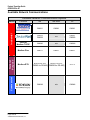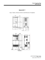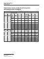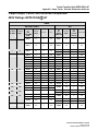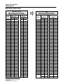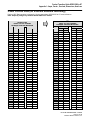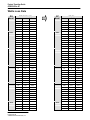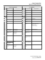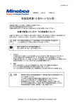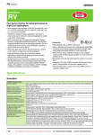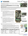
1
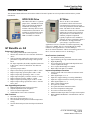
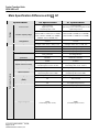
Product Transition Guide
GPD 515/G5 to G7
PL.G7.02.Transition Guide
Product Transition Guide
GPD515/G5 to G7
NOTICE
The information contained within this document is the proprietary property of Yaskawa Electric
America, Inc., and may not be copied, reproduced or transmitted to other parties without the expressed
written authorization of Yaskawa Electric America, Inc. No patent liability is assumed with respect to
the use of the information contained herein. Moreover, because Yaskawa is constantly improving its
high-quality products, the information contained in this document is subject to change without notice.
Every precaution has been taken in the preparation of this document. Nevertheless, Yaskawa assumes no
responsibility for errors or omissions. Neither is any liability assumed for damages resulting from the
use of the information contained in this publication.
__________________________
PL.G7.02.TransitionGuide 4/21/04
Page 2 of 38
Yaskawa Electric America, Inc
Product Transition Guide
GPD515/G5 to G7
Contents
Feature Overview ....................................................................................................... 5
G7 Benefits vs. G5 ..................................................................................................... 5
Main Specification Differences G5 to G7 ................................................................... 6
Physical Dimensions .................................................................................................. 9
I/O Terminal Cross Reference G5 to G7.................................................................. 11
Physical I/O Block Terminal Layout .......................................................................... 14
Main Power Terminal Comparison ........................................................................... 14
Available Network Communications ......................................................................... 16
Appendix 1................................................................................................................ 17
Amps, Carriers, Overload, Watt Loss and Dimensions .....................................117
Output Amps, Carrier and Overload Comparison
240V Ratings GPD515/G5 to G7 ................................................................ 18
Output Amps, Carrier and Overload Comparison
480V Ratings GPD515/G5 to G7 ................................................................ 19
Mounting Hole Data ..................................................................................... 20
Panel Cut-out Data (for external heatsink mounting) ................................... 21
Watts Loss Data .......................................................................................... 22
Appendix 2................................................................................................................ 23
Parameter Differences ........................................................................................23
__________________________
PL.G7.02.TransitionGuide 4/21/04
Page 3 of 38
Yaskawa Electric America, Inc
Product Transition Guide
GPD515/G5 to G7
Page Intentionally Left Blank
__________________________
PL.G7.02.TransitionGuide 4/21/04
Page 4 of 38
Yaskawa Electric America, Inc
Product Transition Guide
GPD515/G5 to G7
Feature Overview
This document details differences between the GPD515/G5 and G7 product to assist in product transition and new product
introduction.
GPD515/G5 Drive
The GPD 515/G5 drive is a generalpurpose drive, intended for a broad
range of applications in Industrial
Automation. Accordingly, it is
available with many choices of I/O,
communications, and software. It is
available in constant torque ratings,
3/4 to 500 horsepower. The G5
HHP is available to 1500 HP.
G7 Benefits vs. G5
Enhanced G7 Performance
• Auto-tuning 3-Methods (R1/Static/Dynamic)
• World’s first commercial 3-Level Inverter architecture
(480V)
•
Static no load auto-tuning offers same torque accuracy
performance as dynamic auto-tuning at base speed &
below
• DC input compatible (all models) simplified connection
to DC power, removal of internal DC bus choke not
required.
• Open-loop torque control
• Improved closed-loop speed response: 60Hz vs. 30Hz
• Improved open-loop speed response: 10Hz vs. 5Hz
• Improved open-loop speed range: 200:1 vs. 100:1
• Higher output frequency resolution: 0.001% vs. 0.01%
• Improved torque response: 300Hz vs. 150Hz
• Improved open loop starting torque: 0.3Hz vs. 0.5Hz
• Improved input voltage specification: 240 vs. 230 and
480 vs. 460.
New Keypad/Digital Operator
• Enhanced digital operator with copy function
• Simplified parameter menu navigation
• New LCD contrast adjustment
• Standard RJ-45 CAT-5 cable connection
New Functions
• New PID sleep function
• More preset speed selections: 17 vs. 9
• New automatic derating based on ambient temperature
setting
• New Bi-directional speed search with speed estimation
mode
G7 Drive
The G7 AC drive is the ultimate
performance solution with increased
speed and torque response to provide
servo-like performance from an induction
motor. The 480V G7 drive has the
world’s first commercial 3-Level Inverter
architecture for total system protection.
This patented 3-Level architecture can
eliminate peripheral components
typically required to solve installation
problems. G7 drive performance makes it
the ideal drive for high performance
speed, torque, or position control
applications. The G7 is available in constant torque/heavy duty
ratings 0.5 to 500HP. The G7 is not intended for the simple,
routine AC drive application, it is for the challenges.
(Refer to Yaskawa document “TR.G7.01 Technology Review G7
Drive” for more details on new G7 Technology.)
New Functions (continued)
• Six additional monitor parameters
• Improved Energy Savings- manual/automatic modes
• High Slip Braking
• New cooling fan on/off control and elapsed time and
cassette replacement design
• New 12-pulse diode bridge 18.5-300kW
• Built-in DC-link choke 18.5-300kW
Improved Input/Output Functions
• Analog outputs with new 4-20mA selection and 10 bit
resolution.
• More digital inputs: 12 vs. 8
• Inputs now support sinking or sourcing (PNP/NPN)
• Inputs now support internal or external power supply
• More digital outputs 6 vs. 4
• More versatile analog outputs
• New pulse I/O (32kHz)
• New quick disconnect terminal I/O block
• New motor temperature analog input
• New motor overheat alarm outputs
• Additional under-torque and over-torque selection points
• Built-in RS485 Modbus RTU communication with self
test mode
__________________________
PL.G7.02.TransitionGuide 4/21/04
Page 5 of 38
Yaskawa Electric America, Inc
Product Transition Guide
GPD515/G5 to G7
Main Specification Differences G5 to G7
Performance Features
Ratings
Specification
G5 Specification
G7 Specification
Control mode
V/f, V/f w/ PG,
Open-loop vector,
Closed-loop flux vector
V/f, V/f w/ PG,
Open-loop vector, Closed-loop flux vector,
Open-loop vector 2
Inverter capacity range
460V 0.4kW to 300kW (0.5 to 400HP)
230V 0.4kW to 110kW (0.5 to 150HP)
575V 1.5kW to 160kW (2 to 200HP)
Modular: 300 to 1800HP (VT)
480V 0.4kW to 300kW (0.5 to 400HP)
240V 0.4kW to 110kW (0.5 to 150HP)
Main power circuit
configuration
2-Level
3-Level
Rated output current
Example: 240V class, 3.7kW, 17.5A
Example: 240V class, 3.7kW, 18A
ASR scan time
2msec
1.25msec (except Open-loop vector 2)
CASE scan time
5msec
2.5msec (except Open-loop vector 2)
I/O Sequence Scan Time
5msec
2.5msec (except Open-loop vector 2)
Microprocessor
First generation
Second generation
Output current limit
protection
Hardware
Hardware, Software
Output frequency resolution
0.01Hz
0.001Hz
Speed control accuracy
Open-loop vector: ±0.2%,
Closed-loop flux vector: ±0.02%
Open-loop vector 2: ±0.1%,
Closed-loop flux vector: ±0.01%
Speed control range
Open-loop vector: 100:1
Open-loop vector 2: 200:1
Speed response
Open-loop vector: 5Hz
Closed-loop flux vector: 30Hz
Open-loop vector 2: 10Hz
Closed-loop flux vector: 60Hz
Starting torque
Open-loop vector: 150% at 1Hz
Open-loop vector 2: 150% at 0.3Hz
Motor surge protection
(480V)
No
Yes (3-Level)
Open loop torque control
No
Yes (Open-loop vector 2)
Torque reference scan time
2msec
1.25msec (except Open-loop vector 2)
Torque response
150Hz
(Closed-loop flux vector)
300Hz
(Closed-loop flux vector)
__________________________
PL.G7.02.TransitionGuide 4/21/04
Page 6 of 38
Yaskawa Electric America, Inc
G7 Specification
I/O
Specification
Quick disconnect I/O
terminals
No
Yes
Programmable functions
39
45
Quantity
0-±10VDC x 2
0-±10VDC/4-20mA x 2
Type
-10-10VDC x 2
(8 bit plus sign)
-10-10VDC or 4-20mA x 2
(8 bit plus sign)
Programmable functions
27
30
Quantity
8
12
Type
24VDC, NPN
Photo coupler isolation, 8mA
24VDC, sinking or sourcing (NPN/PNP)
Photo coupler isolation, 8mA
Internal or external power supply
Programmable functions
45
51
Quantity
4
6
Design
Features
Cooling
Fan
Stopping
Pulse
Output
Pulse
Input
Digital
Outputs
Digital
Inputs
Analog
Outputs
G5 Specification
Analog
Inputs
Product Transition Guide
GPD515/G5 to G7
Type
• Qty 1: Programmable: Form A,
250VAC, 1A, 30VDC, 1A
• Qty 1: Dedicated Fault, Form C,
250VAC, 1A, 30VDC, 1A
• Qty 2: Programmable, photocoupler (open collector output),
48V, 50mA, common emitter
connection
• Qty 3: Programmable: Form A,
250VAC, 1A, 30VDC, 1A
• Qty 1: Dedicated Fault, Form C,
250VAC, 1A, 30VDC, 1A
• Qty 2: Programmable, photo-coupler
(open collector output), 48V, 50mA,
separate emitter connection
Quantity
0
1
Signal level
~
0-32kHz, low level: 0.0-0.8VDC high
level: 3.5-13.2VDC, duty cycle: 30-70%,
3kohm
Programmable functions
~
4
Quantity
0 standard (1 with option)
1
~
0-32kHz, 9.0VDC, 2.2kohm
Programmable functions
~
6
Braking DB transistor
Built-in to G5M27P5 (10HP)
Built-in to G5M4015 (25HP)
Built-in to G7U2015 (20HP)
Built-in to G7U4015 (25HP)
Flux/High slip braking
No
Yes
Modular replacement
No
Yes
Signal level
On/Off control
No
Yes
Cumulative fan operation
time
No
Yes
Auto-tuning
Rotational
Rotational
Stationary
Stationary (primary resistance only)
__________________________
PL.G7.02.TransitionGuide 4/21/04
Page 7 of 38
Yaskawa Electric America, Inc
Product Transition Guide
GPD515/G5 to G7
Storage
Temp
Service Conditions
Network
Communications
Keypad/Operator
Harmonics
Design
Features
Specification
G5 Specification
G7 Specification
Multi-step speed operation
9-step speeds
17-step speeds
PID sleep mode
No
Yes
User customized
programming
No
Yes (DriveWorks EZ)
Speed search
Current Detection
Uni-Directional
Current Detection or Speed Estimation
Bi-directional for Speed Estimation
Split front cover
No
Yes
Timer Function
On/Off delay (0.0-25.5sec)
On/Off delay (0.0-300.0sec)
Run permissive
No
Yes
Motor temperature input
No
Yes
Undertorque detection
No
Yes
12-phase rectification input
No
240V, G7U2018-G7U2110
480V, G7U4018-G7U4300
DC choke built-in
230V, G5M2018-G5M2075
460V, G5M4018-G5M4160
240V, G7U2018-G7U2110
480V, G7U4018-G7U4300
Constant access level
selection
3-level selectable
(Quick-Start, Basic, Advanced)
2-level selectable
(Quick-Program, Advanced)
Copy function
No (optional keypad)
Yes
Display
2 Line x 16 Character LCD
5 Line x 16 Character LCD
(Contrast Adjustable)
Monitoring
1 monitor
3 sequential monitors at same time
Verify function
Yes
Modified constants can be displayed.
Viewable monitors
35
40
Built-in
Modbus RTU (RS-232, 9.6kbps)
Modbus RTU (RS-232/422/485, 19.2kbps)
Option Card
Modbus RTU (RS-422/485), Ethernet
(Modbus/ TCP/IP), DeviceNet,
Profibus-DP, Modbus Plus
Ethernet (Modbus/ TCP/IP), DeviceNet,
Profibus-DP, Modbus Plus, LonWorks
Input specifications
3-phase, 200-230VAC
3-phase, 380-460VAC,
Tolerance: +10 to -15%
3-phase, 200-240VAC
3-phase, 380-480VAC
Tolerance: +10 to -15%
Vibration/Shock
~
240V: 60HP (2037) and Below, 480V: 75HP
(4045) and Below
1.0G (9.8m/s^2) 10 to 20Hz
0.6G (5.9m/s^2) 20 to 55Hz
240V: 60HP (2045) and Above, 480V: 100HP
(4055) and Above
1.0G (9.8m/s^2) 10 to 20Hz
0.2G (2.0m/s^2) 20 to 55Hz
ºC
-10ºC ~ +60ºC
-20ºC ~ +60ºC
__________________________
PL.G7.02.TransitionGuide 4/21/04
Page 8 of 38
Yaskawa Electric America, Inc
Product Transition Guide
Terminal Comparison
Physical Dimensions
Between 20 - 200 HP, the G7 is 18% smaller volume on average than the equivalent GPD515/G5.
(See appendix 1) Based on meeting NEC full load amp requirements, the G7 footprint can offer a space
savings over the GPD515/G5.
G7– 18% less volume
compared to GPD515/G5
__________________________
PL.G7.02.TransitionGuide 4/21/04
Page 9 of 38
Yaskawa Electric America, Inc
Product Transition Guide
GPD515/G5 to G7
GPD515/G5 Terminal Description
GPD515/G5
Compare to G7
terminals, see
next page.
PL.G7.02.TransitionGuide 4/21/04
Page 10 of 38
Yaskawa Electric America, Inc
Product Transition Guide
GPD515/G5 to G7
G7 Terminal Description
G7
__________________________
PL.G7.02.TransitionGuide 4/21/04
Page 11 of 38
Yaskawa Electric America, Inc
Product Transition Guide
GPD515/G5 to G7
I/O Terminal Cross Reference G5 to G7
GPD515/G5 Terminal
Type
GPD515/G5
Terminal
Default Function
G7 Description
S1
Forward run/stop command
–
S2
Reverse run/stop command
–
2
3
External fault input
S3
External fault input
4
Fault reset input
Master/Aux. change
Multi-step speed ref.1
Multi-step speed ref.2
Jog reference
External baseblock
–
–
–
–
Sequence control input common
–
S4
S6
S7
S8
S9
S10
S11
S12
SN
SC
Fault reset
Multi-step speed reference 1
(Master/auxiliary switch)
Multi-step speed reference 2
Jog frequency reference
External baseblock N.O.
Multi-step speed reference 3
Multi-step speed reference 4
Accel/Decel time select
Emergency Stop N.O.
Digital input common
Factory connected to SP
SP
Factory connected to SC
5
6
7
8
11
–
Analog Input Signals
G7
Terminal
Forward run/stop
Signal level: (Photo-coupler
insulated input: +24VDC, 8mA)
Reverse run/stop
1
Digital Input Signals
Default Function
G7 Terminal
S5
Multi-function digital inputs
Functions set by:
H1-01 to H1-10.
+24VDC, 8mA
Photo coupler isolation
Factory connected for internal
supply, sinking mode.
Refer to G7 User Manual for
other methods.
15
+15VDC Power supply
(20mA maximum)
+V
+15VDC power supply
+15VDC
(20mA maximum)
33
-15VDC Power supply
(20mA maximum)
-V
-15VDC power supply
-15VDC
(20mA maximum)
13
14
16
17
12
Master frequency ref. (voltage)
-10 to +10VDC (20kohm)
0 to +10VDC (20kohm)
Master frequency ref. (current)
4 to 20mA (250ohm)
Multi-function analog input
-10 to +10VDC (20kohm),
0 to +10VDC (20kohm)
Common for control circuit 0V
Connection to shield sheath of
signal lead
PL.G7.02.TransitionGuide 4/21/04
Page 12 of 38
Yaskawa Electric America, Inc
A1
A2
A3
AC
E(G)
0 to +10VDC=100%
Master frequency reference 0 to +/-10VDC=100% (H3-01)
(20kohm)
4 to 20mA=100% (250ohm)
Add to terminal A1
0 to +10VDC=100% (20kohm)
Function set by H3-09.
0 to +10Vdc=100%/(20kohm)
Auxiliary frequency
0 to +/-10Vdc=100%
reference 1
Function set by H3-05
Analog common
–
Shield wire, optional ground
line connection point
–
Product Transition Guide
GPD515/G5 to G7
I/O Terminal Cross Reference G5 to G7
GPD515/G5 Terminal
Type
GPD515/G5
Terminal
9
Digital Output Signals
10
Default Function
During run (NO contact)
Form A dry contact
250VAC1A
30VDC, 1A
G7 Terminal
G7
Terminal
Default Function
Multi-function digital output
Form A dry contact
250VAC, 1A
30VDC, 1A
Function set by H2-01
Multi-function open collector
output
48VDC, 50mA
Function set by H2-04
M1
During run
(N.O. contact)
M2
25
Zero speed detection
Open collector output, 48V, 50mA
P3
Factory setting:
Drive ready
27
Open collector output common
C3
Open collector output common
26
Speed agree detection
Open collector output
48V, 50mA or less
P4
Factory setting:
Fout detect 2
27
18
19
20
Open collector output common
Dedicated fault contact
Form C dry contact
250VAC, 1A
30VDC, 1A
C4
MA
MB
~
MC
~
Zero speed
(N.O. contact)
M4
~
Multi-function digital output
Form A dry contact
250VAC, 1A
30VDC, 1A
Function set by H2-02.
Frequency agree
(N.O. contact)
Output frequency
0 to +10VDC or 0 to ±10VDC
(Max current 2mA) (500ohm)
10VDC or 20mA=100% output
frequency
Function set by H4-01
0 to +10VDC or 0 to ±10VDC
(2mA maximum) (500ohm)
5VDC or 12mA=100% drive
rated current
Function set by H4-04
M6
21
Frequency monitor
10VDC=100% output frequency
(2mA maximum)
23
Current monitor
5VDC=drive rated current
(2mA maximum)
AM
Output current
22
Common (Current Monitor)
AC
Analog common
FM
Dedicated fault contact
Form C dry contact:
250VAC, 1A
30VDC, 1A
Multi-function digital output
Form A dry contact
250VAC, 1A
30VDC, 1A
Function set by H2-03
M5
~
Multi-function open collector
output
48VDC, 50mA
Function set by H2-05
Open collector output common
Fault contact output
M3
Analog Output Signals
G7 Description
–
__________________________
PL.G7.02.TransitionGuide 4/21/04
Page 13 of 38
Yaskawa Electric America, Inc
Product Transition Guide
GPD515/G5 to G7
I/O Terminal Cross Reference G5 to G7
Type
GPD515/G5 Terminal
GPD515/G5
G7 Terminal
G7
Default Function
RS-485/422
Pulse I/O
Terminal
Default Function
Terminal
G7 Description
0-32kHz (3kohm) ±5%
High level: 3.5-13.2VDC
Low level: 0.0-0.8VDC
Duty Cycle: 30%-70%
Function set by H6-01
0-32kHz
Output: +5VDC
Load: 1.5kohm
Function set by H6-06
–
RP
Pulse input
–
MP
Pulse output
–
R+
–
R-
–
S+
–
S-
–
IG
Modbus RTU protocol
Differential input
PHC isolation
Modbus RTU protocol
Differential output
PHC isolation
Signal common
–
–
Physical I/O Block Terminal Layout
G5 Terminal Block
11
1
12 (G)
2
13
3
14
15
4
PL.G7.02.TransitionGuide 4/21/04
Page 14 of 38
Yaskawa Electric America, Inc
16
5
17
6
25
7
26
8
21
27
22
33
23
18
19
9
20
10
Product Transition Guide
GPD515/G5 to G7
Main Power Terminal Comparison
G5 terminal
R L1
S L2
T L3
G7 terminal
R/L1
S/L2
T/L3
R1/L11
S1/L21
T1/L31
U/T1
V/T2
W/T3
B1
B2
U T1
V T2
W T3
B1
B2
1
1
2
3
2
3
r
Function
Main circuit power supply input
Main circuit power supply input (12-pulse units)
Drive output
Braking resistor unit connection
DC power supply input (Connection
1 to )
DC power supply connection (Connection
1 to
DC reactor connection (Connection 1 to 2)
DC reactor connection (Connection 1 to 2)
Braking unit connection (Connection
3 to )
Cooling fan and control power supply
Cooling fan power supply
Control power supply
Cooling fan power supply
r
s200
s400
s
)
Feature availability is model dependant. Refer to the table below.
300kW (500HP)
220kW (350HP)
185kW (300HP)
160kW (250HP)
110kw (150HP)
Not Available
Not Available
Not Available
Available
Not Available
Available
Not Available
Available
Not Available
Available
Not Available
Available
Not Available
Available
Not Available
Available
Available
Available
Available
N.A. (Reactor Built-in)
Special
Available
N.A. (Reactor Built-in)
Available
N.A. (Reactor Built-in)
Available
N.A. (Reactor Built-in)
Available
Available
Available
Available
Available
Standard
Standard
Optional
N.A.
Standard
Standard
Optional
Remove Upper/Lower Covers
Remove Upper/Lower Covers
Remove Upper/Lower Covers
Standard
Remove Upper/Lower Covers
Standard
132kW (200HP)
90kw (125HP)
55kW (75HP)
G7
75kW (100HP)
G5
45kW (60HP)
G7
37kW (50HP)
G5
30kW (40HP)
G7
22kW (30HP)
Open Type
Enclosure
G5
3
15kW (20HP)
NEMA1
Enclosure
(B1)
18.5kW (25HP)
Braking
chopper unit
connection
G7
11kw (15HP)
2
G5
7.5kW (10HP)
1
G7
5.5kW (7.5HP)
DC reactor
connection
G5
3.7kW (5HP)
1
G7
2.2kW (3HP)
DC power
supply input
G5
1.5kW (2HP)
B1,
B2
G7
230V
460V
240V
480V
230V
460V
240V
480V
230V
460V
240V
480V
230V
460V
240V
480V
230V
460V
240V
480V
230V
460V
240V
480V
230V
460V
240V
480V
0.75kW (1HP)
Braking
resistor
connection
G5
0.4kW (0.5HP)
R1,
S1,
T1
Voltage Class
Terminal
12-pulse diode
bridge
Product Series
Function
No Product
No Product
No Product
No Product
No Product
No Product
No Product
No Product
No Product
No Product
No Product
N.A.
No Product
N.A.
No Product
Standard
No Product
__________________________
PL.G7.02.TransitionGuide 4/21/04
Page 15 of 38
Yaskawa Electric America, Inc
Product Transition Guide
GPD515/G5 to G7
Available Network Communications
Yaskawa Network Communication Options
Protocol
G5
G5 HHP
G7
CM061
CM061
CM061
CM053
CM059
n/a
CM057
CM059
Ethernet
Modbus TCP/IP
CM090
n/a
CM090
Modbus Plus
CM071
CM071
CM071
Modbus RTU
Commercial
General
Purpose
Industrial
Market
PL.G7.02.TransitionGuide 4/21/04
Page 16 of 38
Yaskawa Electric America, Inc
Built-in RS-232
Built-in RS-232
[CM085 for RS-485] [CM085 for RS-485]
CM048
n/a
Built-in
CM048
Product Transition Guide
GPD515/G5 to G7
Appendix 1
Amps, Carriers, Overload, Heat loss and Dimension Comparison
____________________________
PL.G7.02.TransitionGuide 4/21/04
Page 17 of 38
Yaskawa Electric America, Inc
Product Transition Guide
GPD515/G5 to G7
Output Amps, Carrier and Overload Comparison
240V Ratings GPD515/G5 to G7
240V
GPD515/G5
G7
GPD515
NEC Motor NEC Motor
HP 240V
Amps
0.5
0.75
1
1.5
2
3
5
7.5
10
15
20
25
2.2
3.2
4.2
6
6.8
9.6
15.2
22
28
42
54
68
30
80
40
50
104
130
60
154
75
100
125
150
192
248
312
360
G5
G7
Output
Amps
Fc kHz
OL %
Model
CIMR-G7U
Output
Amps
Fc
KHz
Overload %
20P41
3.2
15
150
20P41
3.2
15
150
20P71
6
15
150
20P71
6
15
150
21P51
22P21
23P71
25P51
27P51
20111
20151
8
11
17.5
25
33
49
64
15
15
15
15
15
15
15
150
150
150
150
150
150
150
21P51
22P21
23P71
25P51
27P51
20111
20151
8
12
18
27
34
49
66
15
15
15
15
15
15
15
150
150
150
150
150
150
150
20181
80
15
150
20181
80
15
150
20221
96
10
150
20221
96
10
150
20301
130
10
150
20300
130
10
150
20371
20450
20551
20751
-
160
183
224
300
-
10
10
10
10
-
150
150
150
150
-
20370
20450
20550
20750
20900
21100
160
183
224
300
358
415
10
10
10
10
2
2
150
150
150
150
150
150
Model
CIMR-G5M
PL.G7.02.TransitionGuide 4/21/04
Page 18 of 38
Yaskawa Electric America, Inc
Product Transition Guide GPD515/G5 to G7
Appendix 1 –Amps, Carrier , Overload, Dimensions, Heat Loss
Output Amps, Carrier and Overload Comparison
480V Ratings GPD515/G5 to G7
480V
GPD515/G5
G7
GPD515/
NEC Motor NEC Motor
G5
HP 480V
Amps Model CIMRG5M
0.5
1.1
40P41
0.75
1.6
1
2.1
40P71
1.5
3
2
3.4
G7
Output
Amps
Fc
kHz
Overload %
(3-Level
Control)
Output
Amps
Fc kHz
OL%
Model
CIMR-G7U
1.8
15
150
40P41
1.8
8
150
3.4
15
150
40P71
3.4
8
150
41P51
42P21
43P71
44P01
45P51
47P51
40111
40151
40181
40221
40301
40371
40451
40550
40750
4.8
6.2
9
11
15
21
27
34
42
52
65
80
97
128
165
8
8
8
8
8
8
8
8
8
8
8
8
8
5
5
150
150
150
150
150
150
150
150
150
150
150
150
150
150
150
40900
195
3
150
3
4.8
41P51
4.8
15
150
5
7.5
10
15
20
25
30
40
50
60
75
100
125
7.6
11
14
21
27
34
40
52
65
77
96
124
156
150
180
43P71
44P01
45P51
47P51
40111
40151
40181
40221
40301
40371
40451
40551
40751
41101
8
11.7
14
21
27
34
41
52
65
80
96
128
165
224
15
15
15
12.5
12.5
10
10
8
8
6
6
6
6
5
150
150
150
150
150
150
150
150
150
150
150
150
150
150
200
240
-
-
-
-
41100
41320
240
270
3
2
150
150
250
302
41601
41850
302
340
5
2
150
150
41600
302
2
150
300
350
400
500
361
414
477
590
42200
450
2
150
41850
42200
370
450
2
2
150
150
43000
605
2
150
43000
605
2
150
____________________________
PL.G7.02.TransitionGuide 4/21/04
Page 19 of 38
Yaskawa Electric America, Inc
Product Transition Guide
GPD515/G5 to G7
Mounting Hole Data
GPD515/G5
Mounting Hole Data
Model
20P4
20P7
21P5
22P2
23P7
25P5
27P5
2011
2015
2018
2022
2030
2037
2045
2055
2075
40P4
40P7
41P5
42P2
43P7
45P5
47P5
4011
4015
4018
4022
4030
4037
4045
4055
4075
4110
4160
4185
4220
4300
GPD515/G5
(Millimeters)
W1
H1
126
266
126
266
126
266
126
266
126
266
186
285
186
285
236
365
236
365
275
435
275
435
320
650
320
650
370
775
370
775
445
895
126
266
126
266
126
266
126
266
126
266
186
285
186
285
236
365
236
365
275
435
275
435
275
610
275
610
275
610
350
795
350
795
445
895
445
895
750
1400
750
1400
750
1550
PL.G7.02.TransitionGuide 4/21/04
Page 20 of 38
Yaskawa Electric America, Inc
GPD515/G5
(Inches)
W1
H1
4.96
10.47
4.96
10.47
4.96
10.47
4.96
10.47
4.96
10.47
7.32
11.22
7.32
11.22
9.29
14.37
9.29
14.37
10.83 17.13
10.83 17.13
12.60 25.59
12.60 25.59
14.57 30.51
14.57 30.51
17.52 35.24
4.96
10.47
4.96
10.47
4.96
10.47
4.96
10.47
4.96
10.47
7.32
11.22
7.32
11.22
9.29
14.37
9.29
14.37
10.83 17.13
10.83 17.13
10.83 24.02
10.83 24.02
10.83 24.02
13.78 31.30
13.78 31.30
17.52 35.24
17.52 35.24
29.53 55.12
29.53 55.12
29.53 61.02
G7
Mounting Hole Data
Model
20P4
20P7
21P5
22P2
23P7
25P5
27P5
2011
2015
2018
2022
2030
2037
2045
2055
2075
2090
2110
40P4
40P7
41P5
42P2
43P7
45P5
47P5
4011
4015
4018
4022
4030
4037
4045
4055
4075
4090
4110
4132
4160
4185
4220
4300
G7
(Millimeters)
W1
H1
126
266
126
266
126
266
126
266
126
266
186
285
186
285
216
335
216
335
195
385
220
435
250
575
250
575
325
700
325
700
370
820
445
855
445
855
126
266
126
266
126
266
126
266
126
266
186
285
186
285
216
335
216
335
220
435
220
435
260
535
260
535
260
535
325
700
325
700
370
820
370
820
445
895
445
895
1270
540
1270
540
1440
730
G7
(Inches)
W1
H1
4.96
10.47
4.96
10.47
4.96
10.47
4.96
10.47
4.96
10.47
7.32
11.22
7.32
11.22
8.50
13.19
8.50
13.19
7.68
15.16
8.66
17.13
9.84
22.64
9.84
22.64
12.80
27.56
12.80
27.56
14.57
32.28
17.52
33.66
17.52
33.66
4.96
10.47
4.96
10.47
4.96
10.47
4.96
10.47
4.96
10.47
7.32
11.22
7.32
11.22
8.50
13.19
8.50
13.19
8.66
17.13
8.66
17.13
10.24
21.06
10.24
21.06
10.24
21.06
12.80
27.56
12.80
27.56
14.57
32.28
14.57
32.28
17.52
35.24
17.52
35.24
21.26
50.00
21.26
50.00
28.74
56.69
Product Transition Guide GPD515/G5 to G7
Appendix 1 –Amps, Carrier , Overload, Dimensions, Heat Loss
Panel Cut-out Data (for external heatsink mounting)
Refer to NEC Ratings tables in Appendix 1 for the appropriate GPD515/G5 to G7 cross-reference.
Note: Ampacity ratings vary between GPD515/G5 to G7 models
G7
GPD515/G5
PANEL CUT OUT OPENING
EXTERNAL HEATSINK MOUNTING
Model
20P4
20P7
21P5
22P2
23P7
25P5
27P5
2011
2015
2018
2022
2030
2037
2045
2055
2075
40P4
40P7
41P5
42P2
43P7
45P5
47P5
4011
4015
4018
4022
4030
4037
4045
4055
4075
4110
4160
4185
4220
4300
Millimeters
W
H
(mm)
(mm)
138
271
138
271
138
271
138
271
138
271
180
298
180
298
200
377
200
377
300
404
300
404
380
627
380
627
451
756
451
756
555
894
138
271
138
271
138
271
138
271
138
271
180
298
180
298
200
377
200
377
300
404
300
404
309
571
309
571
309
571
440
761
440
761
555
894
555
894
875
1324
875
1324
873
1475
Inches
W
(Inches)
5.43
5.43
5.43
5.43
5.43
7.09
7.09
7.87
7.87
11.81
11.81
14.96
14.96
17.76
17.76
21.85
5.43
5.43
5.43
5.43
5.43
7.09
7.09
7.87
7.87
11.81
11.81
12.17
12.17
12.17
17.32
17.32
21.85
21.85
34.45
34.45
34.37
H
(Inches)
10.67
10.67
10.67
10.67
10.67
11.73
11.73
14.84
14.84
15.91
15.91
24.68
24.68
29.76
29.76
35.20
10.67
10.67
10.67
10.67
10.67
11.73
11.73
14.84
14.84
15.91
15.91
22.48
22.48
22.48
29.96
29.96
35.20
35.20
52.13
52.13
58.07
PANEL CUT OUT OPENING
EXTERNAL HEATSINK MOUNTING
Model
20P4
20P7
21P5
22P2
23P7
25P5
27P5
2011
2015
2018
2022
2030
2037
2045
2055
2075
2090
2110
40P4
40P7
41P5
42P2
43P7
44P0
45P5
47P5
4011
4015
4018
4022
4030
4037
4045
4055
4075
4090
4110
4132
4160
4185
4220
4300
Millimeters
W
H
(mm)
(mm)
138
271
138
271
138
271
138
271
138
271
197
298
197
298
233
353
233
353
244
369
269
419
359
545
359
545
434
673
434
673
484
782
555
817
555
817
138
271
138
271
138
271
138
271
138
271
138
271
197
298
197
298
233
353
233
353
269
419
269
419
309
519
309
519
309
519
434
673
434
673
484
782
484
782
555
817
555
817
693
1227
693
1227
875
1397
Inches
W
H
(Inches) (Inches)
5.43
10.67
5.43
10.67
5.43
10.67
5.43
10.67
5.43
10.67
7.76
11.73
7.76
11.73
9.17
13.90
9.17
13.90
9.61
14.53
10.59
16.50
14.13
21.46
14.13
21.46
17.09
26.50
17.09
26.50
19.06
30.79
21.85
32.17
21.85
32.17
5.43
10.67
5.43
10.67
5.43
10.67
5.43
10.67
5.43
10.67
5.43
10.67
7.76
11.73
7.76
11.73
9.17
13.90
9.17
13.90
10.59
16.50
10.59
16.50
12.17
20.43
12.17
20.43
12.17
20.43
17.09
26.50
17.09
26.50
19.06
30.79
19.06
30.79
21.85
32.17
21.85
32.17
27.28
48.31
27.28
48.31
34.45
55.00
__________________________
PL.G7.02.TransitionGuide 4/21/04
Page 21 of 38
Yaskawa Electric America, Inc
Product Transition Guide
GPD515/G5 to G7
Watts Loss Data
G5
Model
20P4
20P7
21P5
22P2
23P7
25P5
27P5
2011
2015
2018
2022
2030
2037
2045
2055
2075
40P4
40P7
41P5
42P2
43P7
44P0
45P5
47P5
4011
4015
4018
4022
4030
4037
4045
4055
4075
4110
4160
4185
4220
4300
GPD515/G5 (W)
Internal Heatsink
50
15
65
25
80
40
60
80
80
135
90
210
110
235
160
425
200
525
230
655
280
830
440
930
620
1110
660
1380
890
1740
1160
2050
50
10
65
20
80
30
60
65
65
80
80
120
85
135
120
240
150
305
180
390
195
465
260
620
315
705
370
875
415
970
710
1110
890
1430
1160
1870
1520
2670
1510
3400
2110
4740
2910
6820
PL.G7.02.TransitionGuide 4/21/04
Page 22 of 38
Yaskawa Electric America, Inc
Total
65
90
120
140
215
300
725
585
725
885
1110
1370
1730
2040
2630
3210
60
85
110
125
145
200
220
360
455
570
660
880
1020
1245
1385
1820
2320
3030
4190
4910
6850
9730
G7
Model
20P4
20P7
21P5
22P2
23P7
25P5
27P5
2011
2015
2018
2022
2030
2037
2045
2055
2075
2090
2110
40P4
40P7
41P5
42P2
43P7
44P0
45P5
47P5
4011
4015
4018
4022
4030
4037
4045
4055
4075
4090
4110
4132
4160
4185
4220
4300
G7 (W)
Internal Heatsink
36
21
42
43
47
58
53
83
64
122
87
187
112
263
136
357
174
473
241
599
257
679
362
878
434
1080
510
1291
607
1474
823
2009
871
1660
1194
2389
39
10
44
21
46
33
49
41
63
77
66
100
80
132
107
197
116
246
135
311
174
354
210
516
246
633
285
737
340
929
488
1239
597
1554
762
1928
928
2299
1105
2612
1501
3614
1995
4436
2205
5329
2941
6749
Total
57
85
105
136
186
274
375
493
647
840
936
1240
1514
1801
2081
2832
2531
3583
49
65
79
90
140
166
212
304
362
446
528
726
879
1022
1269
1727
2151
2690
3227
3717
5115
6431
7534
9690
Product Transition Guide
Appendix 2- Parameter Differences
Appendix 2
Parameter Differences
The following parameter list shows the differences
between GPD515/G5 and G7 parameters. Parameters not
listed are identical between GPD515/G5 and G7. Refer to
the G7 instruction manual for details on specific
parameter functions. Parameters are listed alphabetically
by GPD515/G5.
____________________________
PL.G7.02.TransitionGuide 4/21/04
Page 23 of 38
Yaskawa Electric America, Inc
Product Transition Guide
GPD515/G5 to G7
GPD515/G5 Parameters
Name
Parameter
(Digital Operator Display)
No.
A1-01
Access Level
G7 Parameters
Setting or Selection
0: Operation Only
1: User Level
2: Quick-Start [Q]
3: Basic Level [B]
4: Advanced Level [A]
Name
Parameter
(Digital Operator Display)
No.
Access Level Selection
A1-01
Remarks on
Setting or Selection
Removed:
3: Basic Level [B]
Modified selection:
2: Advanced Level
A1-02
Control Method Selection 0: V/F control without PG
1: V/F control with PG
2: Open Loop Vector
3: Flux Vector
A1-02
Control Method Selection Additional function:
4: Open Loop Vector control 2
B1-01
Reference Selection
0: Operator
1: Terminals
2: Communication Serial Com
3: Option PCB
4: EWS Reference from CP-717
b1-01
Reference Selection
Changed to:
4: Pulse Input
B1-02
Operation Method
Selection
0: Operator
1: Terminals
2: Communication Serial Com
3: Option PCB
4: EWSRun from CP-717
b1-02
Run Command Selection
Removed selection 4:
4: EWSRun from CP-717
B3-01
Speed Search Selection at 0: Disabled
1: Enabled
Start
b3-01
Speed Search Selection
—
—
—
b3-05
Modified selections:
0: Speed Estimation Speed Search Disable
1: Speed Estimation Speed Search Enable
2: Current Detection Speed Search Disable
3: Current Detection Speed Search Enable
Speed Search Delay Time New Parameter
—
—
—
b5-15
Sleep Function Start Level New Parameter
—
—
—
b5-16
Sleep Delay Time
New Parameter
—
b5-17
PID Accel/Decel Time
New Parameter
b8-01
Energy Saving Control
Selection
Changed Parameter No.
—
—
B8-03
Energy -saving Mode
Selection
0:Disabled
1:Enabled
B8-04
Energy-saving Control
Gain
—
b8-02
Energy Saving Gain
Changed Parameter No.
B8-05
Energy-saving Control
Time Constant
—
b8-03
Energy Saving Control
Filter Time Constant
Changed Parameter No.
Energy Saving Coefficient New Parameter
Value
Power Detection Filter
—
Time
Search Operation Voltage
—
Limit
Output Voltage Limit
Changed Parameter No.
Opera tion Selection
—
—
—
b8-04
—
—
—
b8-05
—
—
—
b8-06
C3-06
Output Voltage Limit
0:Disabled
Operation Selection
1:Enabled
PL.G7.02.TransitionGuide 4/21/04
Page 24 of 38
Yaskawa Electric America, Inc
C3-05
Product Transition Guide
Appendix 2- Parameter Differences
GPD515/G5 Parameters
Name
Parameter
(Digital Operator Display)
No.
G7 Parameters
Setting or Selection
Name
Parameter
(Digital Operator Display)
No.
Remarks on
Setting or Selection
—
—
—
C6-02
Carrier Frequency
Selection
New parameter function different than old
C6-02 in GPD515/G5
0: Low noise
1: Fc = 2.0 kHz
2: Fc = 5.0 kHz
3: Fc = 8.0 kHz
4: Fc = 10.0 kHz
5: Fc = 12.5 kHz
6: Fc = 15.0 kHz
F: Program Determined by the settings of C603 thru C6-05
C6-01
Carrier Frequency Upper
Limit
Carrier Frequency Lower
Limit
Carrier Frequency
Proportional Gain
—
—
C6-03
Changed Parameter No.
—
C6-04
—
C6-05
—
C6-11
Carrier Frequency
Upper Limit
Carrier Frequency
Lower Limit
Carrier Frequency
Proportional Gain
Carrier Frequency
Selection Open Loop
Vector Control 2
C6-02
C6-03
—
Changed Parameter No.
New Parameter
Select the carrier frequency when open loop
vector control 2 is used.
1: 2 kHz
2: 4 kHz
3: 6 kHz
4: 8 kHz
C7-02
Hunting Prevention
0:Disabled
Selection
1:Enabled
Hunting Prevention Gain
—
n1-02
C8-08
AFR Gain
—
n2-01
Speed Feedback Detection Changed Parameter No.
Control AFR Gain
C8-09
AFR Time Constant
—
n2-02
AFR Time
C7-01
n1-01
Hunting Prevention
Selection
Hunting Prevention Gain
Setting
Changed Parameter No.
Changed Parameter No.
Changed Parameter No.
Changed Parameter No.
—
—
—
n2-03
Speed Feedback Detection New parameter
Control
Sets the time constant to control the amount
AFR Time Constant 2
of change in the speed at low speed.
—
—
—
d1-09
Frequency Reference 9
New Parameter
—
—
—
d1-10
Frequency Reference 10
New Parameter
—
—
—
d1-11
Frequency Reference 11
New Parameter
—
—
—
d1-12
Frequency Reference 12
New Parameter
—
—
—
d1-13
Frequency Reference 13
New Parameter
—
—
—
d1-14
Frequency Reference 14
New Parameter
—
—
—
d1-15
Frequency Reference 15
New Parameter
—
—
—
d1-16
Frequency Reference 16
New Parameter
D1-09
Jog Frequency Reference
d1-17
Jog Frequency Reference
Changed Parameter No.
—
—
—
d2-03
Master Speed Reference
Lower Limit
New Parameter
—
—
—
d6-01
Magnetic Field Weakening New Parameter
Level
—
—
—
d6-02
Magnetic Field Frequency New Parameter
____________________________
PL.G7.02.TransitionGuide 4/21/04
Page 25 of 38
Yaskawa Electric America, Inc
Product Transition Guide
GPD515/G5 to G7
GPD515/G5 Parameters
Parameter
Name
No.
(Digital Operator Display)
—
G7 Parameters
Setting or Selection
—
—
Parameter
Name
(Digital Operator Display)
No.
d6-03
E1-02
Motor Selection
L1-01
0:Std Fan-Cooled
1:Std Blower-Cooled
2:Vector Motor
—
E2-11
Remarks on
Setting or Selection
Magnetic Field Forcing
Function Selection
New Parameter
0:Disabled
1:Enabled
Motor Overload Protection Changed Parameter No.
Selection
Additional selection
0: Disabled
1: Standard Fan Cooled
2: Standard Blower Cooled
3: Vector Motor
Motor Rated Output
New Parameter
This value is automatically set during auto
tuning.
Motor 2 Control Method Additional selection
Selection
4: Open Loop Vector Control 2
E3-01
Motor 2 Control Method 0: V/F control
1: V/F with PG Feedback
Selection
2: Open Loop Vector
3: Flux Vector
E3-01
E4-01
Motor 2 Max. Output
Frequency
Motor 2 Max.Voltage
—
E3-02
—
E3-03
E4-03
Motor 2 Max.
Voltage Frequency
Base Frequency
—
E3-04
E4-04
Motor 2 Mid.
Output Frequency 1
Mid Frequency
—
E3-05
Motor 2 Mid Output
Frequency
Mid Frequency
Changed Parameter No.
E4-05
Motor 2 Mid.
Output Frequency
Voltage 1
Mid Voltage
—
E3-06
Motor 2 Mid Output
Voltage VA
Mid Voltage
Changed Parameter No.
E4-06
—
E3-07
—
E3-08
Motor 2 Minimum Output Changed Parameter No.
Frequency
Min Frequency
Motor 2 Minimum Output Changed Parameter No.
Voltage
Min Voltage
—
—
—
E4-01
E4-02
E4-03
Motor 2 Rated Current
Changed Parameter No.
Motor 2 Rated Slip
Changed Parameter No.
Motor 2 No-Load Current Changed Parameter No.
—
E4-04
Motor 2 Number of Poles Changed Parameter No.
—
E4-05
E5-06
Motor 2 Min.
Output Frequency
Min Frequency
Motor 2 Min.
Output Frequency
Voltage
Min Voltage
Motor 2 Rated Current
Motor 2 Rated Slip
Motor 2
No-load Current
Motor 2
Number of poles
Motor 2 Line-to-line
Resistance
Motor 2 Leak Inductance
—
E4-06
—
—
—
E4-07
Motor 2 Line-to-Line
Resistance
Motor 2 Leakage
Inductance
Motor 2 Rated Output
—
—
—
F4-07
AO-12 Channel 1 Signal
Level
—
—
—
F4-08
AO-12 Channel 2 Signal
Level
E4-02
E4-07
E5-01
E5-02
E5-03
E5-04
E5-05
PL.G7.02.TransitionGuide 4/21/04
Page 26 of 38
Yaskawa Electric America, Inc
Motor 2 Maximum Output Changed Parameter No.
Frequency
Motor 2 Maximum Output Changed Parameter No.
Voltage
Motor 2 Base Frequency Changed Parameter No.
Base Frequency
Changed Parameter No.
Changed Parameter No.
New Parameter
This value is automatically set during autotuning.
New Parameter
Sets the range of the voltage output.
0: 0 to 10 Vdc
1: -10 to +10 Vdc
New Parameter
Sets the range of the voltage output.
0: 0 to 10 Vdc
1: -10 to +10 Vdc
Product Transition Guide
Appendix 2- Parameter Differences
GPD515/G5 Parameters
Name
Parameter
(DigitalOperator Display)
No.
G7 Parameters
Setting or Selection
Name
Parameter
(Digital Operator Display)
No.
Remarks on
Setting or Selection
—
—
—
F5-03
DO-08 Channel 3 Output New Parameter
Selection
—
—
—
F5-04
DO-08 Channel 4 Output New Parameter
Selection
—
—
—
F5-05
DO-08 Channel 5 Output New Parameter
Selection
—
—
—
F5-06
DO-08 Channel 6 Output New Parameter
Selection
—
—
—
F5-07
DO-08 Channel 7 Output New Parameter
Selection
—
—
—
F5-08
DO-08 Channel 8 Output New Parameter
Selection
—
—
—
F5-09
DO-08 Output Mode
Selection
New Parameter
0:8-channel individual outputs.
1:Binary code output.
2:Output according to
F5-01 to F5-08 settings.
F9-02
Option External Fault
Detection Selection
0:Always Detected
1:Only During Run
F6-02
Option External Fault
Detection Selection
Changed Parameter No.
F9-03
Option External Fault
Detection Operation
Selection
0: Ramp to Stop
1: Coast to Stop
2: Fast - Stop
3: Alarm Only
F6-03
Option External Fault
Detection Operation
Selection
Changed Parameter No.
F9-04
Trace Sampling Time
F6-04
Trace Sampling from
Communications Option
Board
Changed Parameter No.
F9-05
TorqueReference/
F6-06
Torque Reference/Torque Changed Parameter No.
Limit Selection through
DP- RAM communication
F6-01
DP-RAM Communication Changed Parameter No.
Error Detection Operation
Selection
Torque Limit Selection
through DP-RAM
communication
F9-06
—
0: Disabled
1: Enabled
DP-RAM Communication 0:Ramp to Stop
Error Detection Operation 1:Coast to Stop
Selection
2:Fast - Stop
3:Alarm Only
____________________________
PL.G7.02.TransitionGuide 4/21/04
Page 27 of 38
Yaskawa Electric America, Inc
Product Transition Guide
GPD515/G5 to G7
GPD515/G5 Parameters
Name
Parameter (DigitalOperator Display)
No.
Setting or Selection
G7 Parameters
Name
Parameter (Digital Operator Display)
No.
Remarks on
Setting or Selection
Modified selection:
C: Multi-function Analog Input Selection
H1-01
Terminal 3 Selection
Multi-function input terminal 3
0: 3-Wire Control
1: Local/Remote Selection
2: Option/Inverter Selection
3: Multi-Step Reference 1
4: Multi-Step Reference 2
5: Multi-Step Reference 3
6: Jog Frequency Reference
7: Multi-Accel/Decel 1
8: External Baseblock N.O.
9: External Baseblock N.C.
A: Accel/Decel Ramp Hold
B: OH2 Alarm Signal
C: Terminal 16 Enable
D: V/F Mode Select
E: ASR Integral Reset
F: Terminal Not Used
10: MOP Increase
11: MOP Decrease
12: Forward Jog
13: Reverse Jog
14: Fault Reset
15: Fast-Stop N.O.
16: Motor 2 Select
17: Fast Stop N.C. input
18: Timer Function
19: PID Disable
1A: Multi-Accel/Decel 2
1B: Program Lockout
1C: Trim Control Increase
1D: Trim Control Decrease
1E: Ref Sample Hold
1F: Terminal 13/14 Switch
24: External Fault
30: PID Integral Reset
31: PID Control Integral Hold
60: DC Injection Activate
61: Speed Search 1
62: Speed Search 2
63: Energy Save Mode
64: Speed Search 3
65: KEB Ridethrough N.C.
66: KEB Ridethrough N.O
71: Speed/Torque Control Change
72: Zero Servo Command
77: ASR Gain Switch
PL.G7.02.TransitionGuide 4/21/04
Page 28 of 38
Yaskawa Electric America, Inc
Additional selections:
32: Multi-Step Reference 4
34: PID Soft Starter Cancel
35: PID Input Error Polarity Change
67: Communications Test Mode
68: High Slip Braking
78: Polarity Reversing Command for
External Torque Control
H1-01
Multi-Function Digital
Input Terminal S3
Function Selection
Product Transition Guide
Appendix 2- Parameter Differences
GPD515/G5 Parameters
Name
Parameter (DigitalOperator Display)
No.
G7 Parameters
Setting or Selection
Name
Parameter (Digital Operator Display)
No.
Remarks on
Setting or Selection
H1-02
Terminal 4
Selection
—
H1-02
Multi-Function Digital
Input Terminal S4
Function Selection
H1-03
Terminal 5 Selection
—
H1-03
Multi-Function Digital
Input Terminal S5
Function Selection
Terminal number renamed
H1-04
Terminal 6 Selection
—
H1-04
Multi-Function Digital
Input Terminal S6
Function Selection
Terminal number renamed
H1-05
Terminal 7 Selection
—
H1-05
Multi-Function Digital
Input Terminal S7
Function Selection
Terminal number renamed
H1-06
Terminal 8 Selection
—
H1-06
Multi-Function Digital
Input Terminal S8
Function Selection
Terminal number renamed
—
—
—
H1-07
Multi-Function Digital
Input Terminal S9
Function Selection
New Parameter
—
—
—
H1-08
Multi-Function Digital
Input Terminal S10
Function Selection
New Parameter
—
—
—
H1-09
Multi-Function Digital
Input Terminal S11
Function Selection
New Parameter
—
—
—
H1-10
Multi-Function Digital
Input Terminal S12
Function Selection
New Parameter
Terminal number renamed
____________________________
PL.G7.02.TransitionGuide 4/21/04
Page 29 of 38
Yaskawa Electric America, Inc
Product Transition Guide
GPD515/G5 to G7
GPD515/G5 Parameters
Name
Parameter
(DigitalOperator Display)
No.
G7 Parameters
Setting or Selection
Name
Parameter
(Digital Operator Display)
No.
Remarks on
Setting or Selection
H2-01
Multi-function Output
Terminal 9-10
—
H2-01
H2-02
Multi-function Output
Terminal 25/27
Open Collector
Multi-function Output
Terminal 26/27
Open Collector
—
—
H2-02
—
H2-03
Terminal M5-M6
Function Selection
—
H2-04
—
H2-05
—
H3-01
Terminal P3 Function
New Parameter
Selection
Open Collector
Terminal P4 Function
New Parameter
Selection
Open Collector
Terminal A1 Signal Level Terminal number renamed
Selection
H2-03
—
—
—
H3-01
Signal Level Selection
Terminal 13
H3-02
Terminal 13 Gain
H3-03
Terminal 13 Bias
H3-04
Terminal 16 Signal Level
Selection
Terminal 16
Multifunction Analog
Input
H3-05
Frequency reference gain of AI14U, AI-14B 3ch addition input,
DI-08, and DI-16 is common.
0:0 - 10 VDC
1:10 +10 VDC
Multi-function analog input
selection terminal 16
Terminal M1-M2 Function Additional selections:
32: During Speed Limit
Selection
38: Drive Enable
Terminal M3-M4 Function Terminal number renamed
Selection
Terminal number renamed
H3-02
Terminal A1 Gain Setting Terminal number renamed
H3-03
Terminal A1 Bias Setting Terminal number renamed
H3-04
Terminal A3 Signal Level Terminal number renamed
Selection
Modified selection:
2:Aux Frequency Reference1
Used in conjunction with multi-function
inputs “multi-step frequency reference 1-4”.
0: Auxiliary Reference
1: Frequency Gain
2: Frequency Bias
4: Voltage Bias
5: Accel/Decel Change
6: DC Brake Current
7: Overtorque Level
8: Stall Prevention Level
9: Reference Lower Limit
A: Jump Frequency
B: PID Feedback
C: PID Setpoint
D: Frequency Bias 2
10: Forward Torque Limit
11: Reverse Torque Limit
12: Regenerative Torque Limit
13: Torque reference
14: Torque Compensation
15: Forward/Reverse Torque Limit
1F: Not Used
Additional
3:Aux Frequency Reference 2
Used in conjunction with multi-function
inputs “multi-step frequency reference 1-4”.
E: Motor Temperature
See parameters L1-03 & L1-04.
H3-06
Terminal 16 Gain
—
H3-06
Terminal A3 Gain Setting Terminal number renamed
H3-07
Terminal 16 Bias
—
H3-07
Terminal A3 Bias Setting Terminal number renamed
H3-08
Signal Level
Selection Terminal 14
—
H3-08
Terminal A2 Signal Level Terminal number renamed
Selection
H3-09
Multi-function Analog
Input Terminal 14
—
H3-09
Terminal A2 Function
Selection
H3-10
Terminal 14 Gain
H3-10
Terminal A2 Gain Setting Terminal number renamed
H3-11
Terminal 14 Bias
H3-11
Terminal A2 Bias Setting Terminal number renamed
H3-12
Filter Avg Time
H3-12
Filter Avg Time
PL.G7.02.TransitionGuide 4/21/04
Page 30 of 38
Yaskawa Electric America, Inc
Terminal number renamed
Input is from the A2 terminal for the G7.
Product Transition Guide
Appendix 2- Parameter Differences
GPD515/G5 Parameters
Parameter
Name
No.
(DigitalOperator Display)
H4-01
H4-02
H4-03
H4-04
H4-05
H4-06
H4-07
Monitor Selection
Terminal 21
Terminal 21
Output Gain
Terminal 21Output Bias
Terminal 23 Monitor
Terminal 23
Output Gain
Terminal 23
Output Bias
Analog Output
Signal Selection
G7 Parameters
Setting or Selection
Name
Parameter
(Digital Operator Display)
No.
Remarks on
Setting or Selection
Analog output selection terminal
21 same as F4-01
1: Frequency reference
2: Output frequency
3: Inverter output current
5: Motor speed
6: Output voltage
7: DC bus voltage
8: Output power
9: Torque reference internal
15: External terminal 13 input
voltage
16: External terminal 14 input
voltage
17: External terminal 16 input
voltage
18: Motor secondary current Iq
19: Motor excitation current Id
20: Primary frequency after SFS
21: Speed controller ASR input
22: Speed controller ASR output
23: Speed deviation
24: PID feedback
26: Voltage reference Vq output
27: Voltage reference Vd output
31: Not Used
32: ACR q Output
33: ACR d Output
36: PID Input
37: PID Output
38: PID Reference
—
H4-01
H4-02
Terminal FM Gain Setting Terminal number renamed
—
—
H4-03
H4-04
Terminal number renamed
Terminal number renamed
—
H4-05
—
H4-06
Terminal FM Bias Setting
Terminal AM Monitor
Selection
Terminal AM Gain
Setting
Terminal AM Bias Setting
0: 0 - +10 VDC
1: 10V +10 VDC
H4-07
Terminal FM Signal
Level
Selection
—
H4-08
Terminal AM Signal
Level Selection
Terminal number renamed
0: 0 - 10 Vdc
1: -10 to +10V
2: 4-20 mA*
* Set the analog output jumper CN15 in the
proper position.
New Parameter
0: 0 - 10 Vdc
1: -10 to +10V
2: 4-20 mA*
* Set the analog output jumper CN15 in the
proper position.
Additional selection:
4: Run at D1-04
H5-06
H5-07
Drive Transmit Wait
Time
RTS Control Selection
—
—
H5-04
Stopping Method After
Communication Error
—
—
0: Ramp to Stop
1: Coast to Stop
2: Fast - Stop
3: Alarm Only
—
—
—
—
H4-01Terminal FM
Monitor Selection
Terminal number renamed
15: Terminal A1 Input Level
100% = 10Vdc
16: Terminal A2 Input Level
100% = 10Vdc or 20mA
17: Terminal A3 Input Level
100% = 10Vdc
Removed:
23: Speed deviation
Additional:
42: Motor flux calculation value
43: Motor flux current compensation
44: ASR Output without filter
45: Feedforward Control Output
48: Stabalizing speed during regen
Terminal number renamed
Terminal number renamed
New parameter
New parameter
0: Disabled RTS is always on
1: Enabled RTS turns on only when
sending
____________________________
PL.G7.02.TransitionGuide 4/21/04
Page 31 of 38
Yaskawa Electric America, Inc
Product Transition Guide
GPD515/G5 to G7
GPD515/G5 Parameters
Parameter
Name
No.
(DigitalOperator Display)
G7 Parameters
Setting or Selection
Name
Parameter
(Digital Operator Display)
No.
—
—
—
H6-01
Pulse Train Input
Function Selection
—
—
—
—
—
—
—
—
—
—
—
—
H6-02
H6-03
H6-04
H6-05
—
—
—
H6-06
—
—
—
H6-07
Pulse Train Input Scaling
Pulse Train Input Gain
Pulse Train Input Bias
Pulse Train Input Filter
Time
Pulse Train Monitor
Selection
Pulse Train Monitor
Scaling
Motor Overload
Protection Selection
L1-01
Motor Protection
Selection
MOL Fault Select
0:Disabled
1:Coast to Stop
See: GPD515/G5 E1-02
L1-01
—
—
—
L1-03
Motor Overheat Alarm
Operation Selection
—
—
—
L1-04
Motor Overheat Fault
Oper ation Selection
—
—
—
L1-05
—
—
—
L2-07
—
—
—
L2-08
L3-07
—
—
—
—
—
—
Stall Prevention
Function P Gain
Stall Prevention
Function Integral Time
—
Motor Temperature Input
Filter Time
Momentary Recovery
Time
Frequency Reduction
Gain at KEB Start
—
—
L3-11
—
—
—
L3-12
OV Supression function
selection
OV suppression function
level
Frequency Reference Loss
Detection Selection
L3-08
L4-05
—
Frequency Loss
Detection Selection
0: Stop
1: Run@ 80% PrevRef
—
PL.G7.02.TransitionGuide 4/21/04
Page 32 of 38
Yaskawa Electric America, Inc
—
L4-05
L4-06
Frequency Reference
Level at Loss Frequency
Remarks on
Setting or Selection
New parameter
0: Frequency reference
1: PID feedback value
2: PID setpoint value
New parameter
New parameter
New parameter
New parameter
New parameter
New parameter
Modified function
0: Disabled
1: Fan Cooled <10:1 motor
2:Blower Cooled 10:1 motor
3: Vector Motor 1000:1 motor
New parameter
0: Ramp to Stop
1: Coast to Stop
2: Fast-Stop
3: Alarm Only
New parameter
0: Ramp to Stop
1: Coast to Stop
2: Fast-Stop
New parameter
New parameter
New parameter
Deleted in G7
Deleted in G7
New parameter
New parameter
Modified function
0: Normal Operation - Drive will run at the
frequency reference.
1: Run at L4-06 PrevRef
Drive will run at the
percentage set in L4-06
New parameter
Product Transition Guide
Appendix 2- Parameter Differences
GPD515/G5 Parameters
Parameter
Name
No.
(DigitalOperator Display)
G7 Parameters
Setting or Selection
Name
Parameter
(Digital Operator Display)
No.
Remarks on
Setting or Selection
L6-01
Overtorque
Detection Selection 1
0: Disabled
1: @SpdAgree - Alm
2: At RUN - Alarm
3: @SpdAgree - Flt
4:At RUN - Fault
L6-01
Torque Detection
Selection 1
Additional selections:
5: UL3 at SpeedAgree - Alarm Undertorque
Detec tion is only active during Speed Agree
and operation continues after detection.
6: UL3 at RUN - Alarm Undertorque
Detection is always active and operation
continues after detection.
7: UL3 at Speed Agree - Fault Undertorque
Detection only active during Speed Agree
and drive output will shut down on an OL3
fault.
8: UL3 at RUN - Fault Undertorque
Detection is always active and drive output
will shut down on an OL3 fault.
L6-04
Overtorque
Detection Selection 2
0: Disabled
1: @SpdAgree - Alm
Detected during speed agree
only.
2: At RUN - Alarm
Overtorque detection during
running.
3: @SpdAgree - Flt
Detected during the speed
agree only.
4: At RUN - Fault
Detected during running, and
the inverter trips on OL4.
L6-04
Torque Detection
Selection 2
L8-07
Output phase loss
protection
Short-circuit
Protection Selection
0: Disabled
1: Enabled
0:Disabled
1: Enabled
L8-07
Output phase loss
protection
Output Ground Fault
Detection Selection
Additional selections:
5: UL4 at SpeedAgree - Alarm Undertorque
Detec tion is only active during Speed Agree
and opera tion continues after detection.
6: UL4 at RUN - Alarm Undertorque
Detection is always active and operation
continues after detection.
7: UL4 at Speed Agree - Fault Undertorque
Detection only active during Speed Agree
and drive out put will shut down on an OL4
fault.
8: UL4 at RUN - Fault Undertorque
Detection is always active and drive output
will shut down on an OL4 fault.
Additional selections
2: 2/3 phase loss protection
Changed parameter number
L8-10
L8-09
—
—
—
L8-10
Heatsink Cooling Fan
Operation Selection
—
—
—
L8-11
Heatsink Cooling Fan
Operation Delay Time
—
—
—
L8-12
Ambient Temperature
Setting
New parameter
0: Fan On-Run Mode
1: Fan Always On
New parameter
New parameter
____________________________
PL.G7.02.TransitionGuide 4/21/04
Page 33 of 38
Yaskawa Electric America, Inc
Product Transition Guide
GPD515/G5 to G7
GPD515/G5 Parameters
Parameter
Name
No.
(DigitalOperator Display)
L8-17
L8-19
—
—
G7 Parameters
Setting or Selection
0: Conventional
1: Lower fc
Carrier frequency is decreased
when fout 10Hz and the
load is > 100% iac.
2: Short term OL2
OL occurs after 2 seconds
during low speed
[fout 6Hz] current limit.
3: I-Limit=150%
Current limit is set to 150% of
the inverter rated current.
OL2 Characteristic
0: Disabled-Low frequency OL
Selection at Low Speed
disabled
1: Enabled-Low frequency OL
enabled
—
—
Name
Parameter
(Digital Operator Display)
No.
IGBT Protection
Selection at Low
Frequency
—
—
Deleted in G7
L8-15
OL2 Characteristic
Selection at Low Speeds
Changed parameter number
L8-18
Soft CLA Selection
n3-01
High Slip Braking
Deceleration Frequency
Width
High slip braking decel
frequency width
High Slip Braking Current
Limit
High Slip Braking Dwell
Time at Stop
High Slip Braking
Overload Time
Observer Integral Time
Observer Proportional
Gain
Proportional Gain on HiSpeed Side of Observer
Observer Switching
Frequency
Lo-Speed + Regen
Stability Coefficient 1
Torque Adjustment Gain
Gain for Feeder
Resistance Adjustment
Observer Switching
Frequency 2
Torque Adjustment Gain
2
Low Speed + Regen
Stability Coefficient 2
Observer Gain
Modulation Frequency
Observer Gain
Modulation Frequency 2
Observer Gain
Modulation Rate
Feed Forward Control
Selection
New parameter
0: Disabled
1: Enabled.
New parameter
n3-01
—
—
—
n3-02
—
—
—
n3-03
—
—
—
n3-04
n4-07
n4-08
n4-10
n4-11
n4-15
n4-17
n4-18
n4-28
n4-29
n4-30
n4-32
n4-33
n4-34
—
—
—
n5-01
—
—
—
—
—
—
n5-02
n5-03
PL.G7.02.TransitionGuide 4/21/04
Page 34 of 38
Yaskawa Electric America, Inc
Remarks on
Setting or Selection
Motor Accel Time
Feed Forward
Proportional Gain
New parameter
New parameter
New parameter
New parameter
New parameter
New parameter
New parameter
New parameter
New parameter
New parameter
New parameter
New parameter
New parameter
New parameter
New parameter
New parameter
New parameter
New parameter
0:Disabled
1:Enabled
New parameter
New parameter
Product Transition Guide
Appendix 2- Parameter Differences
GPD515/G5 Parameters
Parameter
Name
No.
(DigitalOperator Display)
O1-01
Monitor Selection
User Monitor Sel
Setting or Selection
Monitor selection
4: Control method
5: Motor speed
6: Output voltage
7: DC bus voltage
8: Output power
9: Torque reference internal
10: Input terminal status
11: Output terminal status
12: Internal Control Status 1
13: Elapsed time
14: Flash software ID number
15: External terminal 13 input
voltage
16: External terminal 14 input
voltage
17: External terminal 16 input
voltage
18: Motor secondary current Iq
19: Motor excitation current Id
20: Primary frequency after SFS
21: Speed controller ASR input
22: Speed controller ASR output
23: Speed deviation
24: PID feedback
25: DI-16 reference
26: Voltage reference Vq output
27: Voltage reference Vd output
28: CPU ID number
32: ACR output of q axis
33: ACR output of d axis
34: First Parameter Causing an
OPE
35: Zero Servo Pulse Count
36: PID Input
37: PID Output
38: PID Setpoint
G7 Parameters
Name
Parameter
(Digital Operator Display)
No.
Remarks on
Setting or Selection
Modified name:
15:Terminal A1 Input Voltage
16:Terminal A2 InputVoltage
17:Terminal A3 Input Voltage
Deleted in G7
23: Speed deviation
Added selections:
29: kWh Lo 4 Digits
30: MWh kWh Hi 5 Digits
39: Memobus Communication Error Code
Transmit Err
40:Heatsink Cooling Fan Operation Time
41: Heatsink Temperature
42: Motor flux calculation value
43: Motor flux current compensation
44: ASR output without filter
45: Feed forward control output
48: Stabalizing speed during regen
____________________________
PL.G7.02.TransitionGuide 4/21/04
Page 35 of 38
Yaskawa Electric America, Inc
Product Transition Guide
GPD515/G5 to G7
GPD515/G5 Parameters
Name
Parameter
(DigitalOperator
No.
Display)
O1-05 Parameter No.
Display Selection
Address Display
Setting or Selection
0:Parameter Number
1:Memobus Address
G7 Parameters
Name
Parameter
(Digital Operator Display)
No.
o1-05
—
—
—
o2-10
—
—
—
o2-12
—
—
—
o2-14
LCD Brightness
Adjustment
Modified function:
Sets the contrast of the digital
operator LCD. A set ting of
“1” is the lightest contrast and
a setting of “5” is the darkest
contrast.
Cumulative CoolingFan New parameter
Operation Time Setting
Fault Trace/Fault
New parameter
History Clear Function 0: Disabled no effect.
1: Enabled - resets U2 and U3
monitors, and returns o2-12 to
zero.
kWh User Monitor
New parameter
Initialization
0: Disabled no change.
1: Enabled - Resets U1-29 to
zero and returns o2-14 to zero.
—
—
—
o3-01
Copy Function
Selection
—
—
—
o3-02
Copy Allowed
Selection
Read Allowable
PL.G7.02.TransitionGuide 4/21/04
Page 36 of 38
Yaskawa Electric America, Inc
Remarks on
Setting or Selection
New parameter
0: COPY SELECT no
function
1: INV -> OP READ - All
parameters are copied from
the Drive to the digital
operator.
2: OP -> INV WRITE - All
parameters are copied from
the digital operator to the
Drive.
3: OP<-->INV VERIFY Parameter settings in the Drive
are compared to those in the
digital operator.
NOTE: When using the copy
function, the Drive model
number o2-04, software
number U1-14, and control
method A1-02 must match or
an error will occur.
New parameter
0: Disabled - No digital
operator copy functions are
allowed.
1: Enabled - Copying allowed
Product Transition Guide
GPD515/G5 to G7
Page intentionally blank
PL.G7.02.TransitionGuide 4/21/04
Page 37 of 38
Yaskawa Electric America, Inc
Product Transition Guide
GPD515/G5 to G7
Yaskawa Electric America, Inc
16555 W. Ryerson Rd
New Berlin, WI
(800)YASKAWA (927-5292) Fax (262) 782-3418
www.drives.com
YEA Document Number: PL.G7.02
4/21/04
Yaskawa Electric America, Inc.©