1
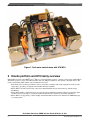
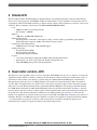
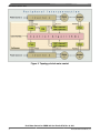
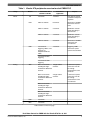
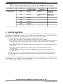
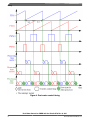
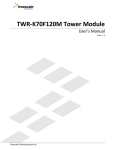
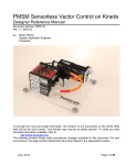
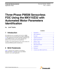
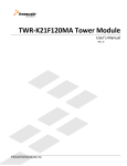
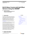
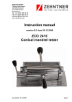
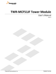
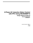
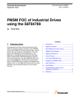
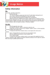
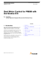
Freescale Semiconductor
Application Note
Document Number: AN4407
Rev. 0, 2011
Dual Motor Control for PMSM with
the Kinetis K70
by:
Pavel Rech
Systems Application Engineer, Microcontroller Solutions Group
Contents
1 Introduction
1
Introduction................................................................1
This application note deals with the field-oriented control
(FOC) of two permanent magnet synchronous motors
(PMSM) with the Kinetis K70 microcontroller (MCU).
2
Kinetis portfolio and K70 family
overview....................................................................2
3
Kinetis K70...............................................................3
4
Dual motor control—K70.........................................3
5
Control algorithm......................................................6
6
Timing.......................................................................7
7
Hardware of dual motor control................................9
8
References.................................................................9
A dual motor control application requires a processor with
high performance and the right set of peripherals for
simultaneous control of two motors. The Kinetis K70 MCU
satisfies both the requirements, with a performance margin for
the application code.
The theoretical aspects of the dual motor control as well as a
short introduction to all the hardware parts and their
realization possibilities on the new K70 processor, are
included in this application note.
© 2011 Freescale Semiconductor, Inc.
Kinetis portfolio and K70 family overview
Figure 1. Dual motor control demo with K70 MCU
2 Kinetis portfolio and K70 family overview
Kinetis MCU is based on the ARM®Cortex™-M4 core. It gives the Kinetis portfolio, a unique position among similar MCUs.
The Kinetis portfolio consists of five MCU families with over 200 pins, peripherals, and software-compatible devices. The
features of the Kinetis MCU families can be summarized as follows:
• Each family offers excellent performance, memory, and feature scalability with common peripherals, memory maps,
and packages, providing easy migration both within and between families.
• Kinetis MCUs are built from Freescale’s innovative 90 nm Thin Film Storage flash technology with the unique
FlexMemory.
• Kinetis MCU families combine the latest low-power innovations and high performance, high-precision mixed signal
capability with a broad range of connectivity, human machine interface, and safety and security peripherals.
• Kinetis MCUs are supported by a market-leading enablement bundle from Freescale and numerous ARM third-party
ecosystem partners.
Dual Motor Control for PMSM with the Kinetis K70, Rev. 0, 2011
2
Freescale Semiconductor, Inc.
Kinetis K70
3 Kinetis K70
The latest family member, the Kinetis K70, has a high performance, rich peripheral integration, and large internal memory.
From a motor control perspective, the K70 MCU enables two high-end motor control algorithms to run in parallel, and a set
of peripherals, namely the FlexTimer and analog-to-digital converters (ADC), enables an interface to the motor control power
electronics. Here is a summary of the features of the Kinetis MK70FN1M0VMJ12 MCU:
• Core:
• ARM Cortex-M4 Core / Floating point unit
• CPU frequency: 120 MHz
• Memory:
• 1 MB flash / 128 KB RAM / 16KB Cache
• Mixed-signal analogue:
• Fast, high-precision 16-bit ADC, 12-bit digital-to-analog converters (DAC), programmable gain amplifiers
(PGA), high-speed comparators (CMP), and an internal voltage reference
• Connectivity and Communications:
• UART, IrDA, I2S, CAN, I2C, USB, and DSPI support
• Timing and Control:
• Powerful FlexTimer (FTM)
• Periodic interrupt timer (PIT)
• Programmable delay block (PDB)
• System:
• 5 V tolerant general-purpose input/output (GPIO) with pin interrupt functionality
• Operational in 1.71-3.6 V voltage range and -40-105 °C temperature range
• 256-pin MAPBGA package with 17x17 mm dimensions
4 Dual motor control—K70
The dual motor control algorithm controls two motors in parallel. The K70 MCU has only one core, therefore, it executes the
algorithm for the first and the second motor, alternately. It reads the phase currents of each motor and detects the voltage of
both inverters, and according to user interface, it generates the pulse-width modulation (PWM) signals of both inverters.
The application requires the correct set of MCU peripherals. For current and voltage measurement, ADCs are needed. At
least two ADCs are required because for each motor, the control needs to measure two phase currents in parallel. Typically,
shunt sensors are used. The measurement must be synchronized with the PWM pulses. For this purpose, the Kinetis family
has a PDB, which synchronizes the ADC with the FTM and provides various delays between them. See Figure 2. After the
necessary delay, it runs the conversion of the two phases currents in parallel. This sequence runs alternately for the first and
the second motor. The current measurement is a hardware process running without code. See Figure 4 on how it works.
Each motor is supplied by its own inverter whose power part is a full bridge. Six PWM signals control the power devices in a
full bridge. Therefore, two FTMs with at least six channels for each motor are required for sensing the mechanical quantities
—rotor speed and the rotor position of each motor. The actual position is obtained by decoding the signals from an
incremental sensor, and the rotor speed is calculated as the position change in time.
Dual Motor Control for PMSM with the Kinetis K70, Rev. 0, 2011
Freescale Semiconductor, Inc.
3
Dual motor control—K70
Figure 2. Topology of dual motor control
Dual Motor Control for PMSM with the Kinetis K70, Rev. 0, 2011
4
Freescale Semiconductor, Inc.
Dual motor control—K70
Table 1. Kinetis K70 peripherals overview for dual PMSM FOC
Group
Module
Timers
PIT
4 channels
1 channel
Time base for speed
calculation and speed
regulation
FTM
FTM1: 8 channels
6 channels
Generation of 6 PWM
channels for the first
motor
FTM2: 2 channels
2 channels
Quadrature encoder
signals decoding for
the first motor
FTM3: 2 channels
2 channels
Quadrature encoder
signals decoding for
second motor
FTM4: 8 channels
6 channels
Generation of 6 PWM
channels for the
second motor
PDB
Submodule and
channels available
Used in the
application
4 channels for
2 channels
triggering 4 ADCs. Two
channels are
multiplexed with two
FTMs
Purpose
Triggering 2 ADC
channels for phase
currents measurement
2 channels for DAC
triggering
4 channels for CMP
triggering
Analog
ADC
ADC1: 32 channels
4 single-ended
including 28 singlechannels
ended and 4 differential
channels
3 channels for phase
current and 1 for DC
bus voltage
measurements of the
first motor
ADC2: 32 channels
4 single-ended
including 28 singlechannels
ended and 4 differential
channels
3 channels for phase
current and 1 for DC
bus voltage
measurements of the
second motor
ADC3: 32 channels
including 28 singleended and 4 differential
channels
ADC4: 32 channels
including 28 singleended and 4 differential
channels
CMP
4 channels
DAC
2 channels
Table continues on the next page...
Dual Motor Control for PMSM with the Kinetis K70, Rev. 0, 2011
Freescale Semiconductor, Inc.
5
Control algorithm
Table 1. Kinetis K70 peripherals overview for dual PMSM FOC (continued)
Group
Module
Submodule and
channels available
Used in the
application
Purpose
Communications
UART
6 channels
1 channel
FreeMASTER
communication
SPI
3 channels
1 channel with 2 chip
selects
MOSFET driver
communications
I2C
2 channels
SDHC
1 channel
USB
1 channel
CAN
2 channel
Ethernet
1 channel
5 Control algorithm
The dual motor control requires running two motor control algorithms in parallel. Figure 3 shows the field-oriented control
(FOC) principle of a PMSM. The key to FOC is to control the motor torque and field excitation, or, the motor magnetic flux,
independently and separately. The operating principles of the two control loops are discussed below:
• The current control loop: The following steps describe the working of this control loop:
a. The two phase currents must be measured in the stator three-phase system of coordinates.
b. The current vector in the stator two-phase system of coordinates, can be obtained using the Clark Transformation.
c. The following Park Transformation rolls the current vector into a rotating two-phase system of coordinates,
according to the measured rotor position.
d. The differences between the measured and required current components are forced into the proportional-integral
(PI) controller.
e. The voltage components obtained from the controllers must be again rolled using the Inverse Park
Transformation.
f. The three components of the phase voltages for the PWM modulator are generated using the Space Vector
Modulation block.
• The speed control loop: It is less complex and determines the deviation between the required speed and the real rotor
speed calculated from the rotor position. The PI controller processes the deviation and creates the required torque
current component.
The field weakening is not implemented, therefore, the required flux current component is kept at zero. A detailed description
of the PMSM vector control application can be found in PMSM Vector Control with Quadrature Encoder on Kinetis, Design
Reference Manual (DRM), available at http://www.freescale.com.
Dual Motor Control for PMSM with the Kinetis K70, Rev. 0, 2011
6
Freescale Semiconductor, Inc.
Timing
Figure 3. Vector control block diagram
6 Timing
The timing is the key for all motor control applications. The timing determines how the processor performance is utilized.
For dual motor control, the processes for individual motors must overlap. It is convenient to set up the FTMs, so that the first
FTM overflow will happen exactly in the middle of the second FTM cycle. See Figure 4. This gives the same processing time
for the fast loops of the first and second motors, so each motor has an available window equal to 50% of the total CPU time.
It is important to prepare such a control algorithm in order to utilize the processor processing time properly. Also, the overlay
enables a decrease in current stress of the DC-bus capacitors due to which the current peaks are spread.
Dual Motor Control for PMSM with the Kinetis K70, Rev. 0, 2011
Freescale Semiconductor, Inc.
7
Timing
Figure 4. Dual motor control timing
Dual Motor Control for PMSM with the Kinetis K70, Rev. 0, 2011
8
Freescale Semiconductor, Inc.
Hardware of dual motor control
7 Hardware of dual motor control
The tower system is a valuable asset of Kinetis MCUs. It is not possible to supply the motor from the MCU pins due to the
voltage and current limitations, therefore, a full bridge consisting of powerful semiconductors is typically used to supply the
motor. Freescale offers a low-level voltage power stage for the tower kits. This power stage not only includes the MOSFET
power devices, but also a driver for the devices, measurement circuits, a protection unit, and power supply. This power stage
fits the tower kit, and thus, a tower system, including the power stage, can be easily built.
The K70 MCU tower does not have natural support for dual motor control. A new tower interconnect board was proposed to
connect selected signals from the secondary and the primary elevator into the connector where the second power stage is
inserted.
Both power stages can be supplied independently from their own sources, or, it is possible to connect to one power supply
through DC buses, in which case, the motors can change energy mutually.
8 References
•
•
•
•
K70 Sub-Family Reference Manual, available at http://www.freescale.com.
TWR-MC-LV3PH User’s Manual, available at http://www.freescale.com.
3-Phase BLDC Motor Control on Kinetis, User’s Guide, available at http://www.freescale.com.
PMSM Vector Control with Quadrature Encoder on Kinetis, DRM, available at http://www.freescale.com.
Dual Motor Control for PMSM with the Kinetis K70, Rev. 0, 2011
Freescale Semiconductor, Inc.
9
How to Reach Us:
Home Page:
www.freescale.com
Web Support:
http://www.freescale.com/support
USA/Europe or Locations Not Listed:
Freescale Semiconductor
Technical Information Center, EL516
2100 East Elliot Road
Tempe, Arizona 85284
+1-800-521-6274 or +1-480-768-2130
www.freescale.com/support
Europe, Middle East, and Africa:
Freescale Halbleiter Deutschland GmbH
Technical Information Center
Schatzbogen 7
81829 Muenchen, Germany
+44 1296 380 456 (English)
+46 8 52200080 (English)
+49 89 92103 559 (German)
+33 1 69 35 48 48 (French)
www.freescale.com/support
Japan:
Freescale Semiconductor Japan Ltd.
Headquarters
ARCO Tower 15F
1-8-1, Shimo-Meguro, Meguro-ku,
Tokyo 153-0064
Japan
0120 191014 or +81 3 5437 9125
[email protected]
Asia/Pacific:
Freescale Semiconductor China Ltd.
Exchange Building 23F
No. 118 Jianguo Road
Chaoyang District
Beijing 100022
China
+86 10 5879 8000
[email protected]
For Literature Requests Only:
Freescale Semiconductor Literature Distribution Center
1-800-441-2447 or +1-303-675-2140
Fax: +1-303-675-2150
[email protected]
Document Number: AN4407
Rev. 0, 2011
Information in this document is provided solely to enable system and software
implementers to use Freescale Semiconductors products. There are no express or implied
copyright licenses granted hereunder to design or fabricate any integrated circuits or
integrated circuits based on the information in this document.
Freescale Semiconductor reserves the right to make changes without further notice to any
products herein. Freescale Semiconductor makes no warranty, representation, or
guarantee regarding the suitability of its products for any particular purpose, nor does
Freescale Semiconductor assume any liability arising out of the application or use of any
product or circuit, and specifically disclaims any liability, including without limitation
consequential or incidental damages. "Typical" parameters that may be provided in
Freescale Semiconductor data sheets and/or specifications can and do vary in different
applications and actual performance may vary over time. All operating parameters,
including "Typicals", must be validated for each customer application by customer's
technical experts. Freescale Semiconductor does not convey any license under its patent
rights nor the rights of others. Freescale Semiconductor products are not designed,
intended, or authorized for use as components in systems intended for surgical implant
into the body, or other applications intended to support or sustain life, or for any other
application in which failure of the Freescale Semiconductor product could create a
situation where personal injury or death may occur. Should Buyer purchase or use
Freescale Semiconductor products for any such unintended or unauthorized application,
Buyer shall indemnify Freescale Semiconductor and its officers, employees, subsidiaries,
affiliates, and distributors harmless against all claims, costs, damages, and expenses, and
reasonable attorney fees arising out of, directly or indirectly, any claim of personal injury
or death associated with such unintended or unauthorized use, even if such claims alleges
that Freescale Semiconductor was negligent regarding the design or manufacture of
the part.
RoHS-compliant and/or Pb-free versions of Freescale products have the functionality and
electrical characteristics as their non-RoHS-complaint and/or non-Pb-free counterparts.
For further information, see http://www.freescale.com or contact your Freescale
sales representative.
For information on Freescale's Environmental Products program, go to
http://www.freescale.com/epp.
Freescale™ and the Freescale logo are trademarks of Freescale Semiconductor, Inc.
All other product or service names are the property of their respective owners.
© 2011 Freescale Semiconductor, Inc.