1
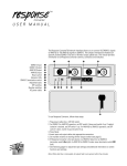
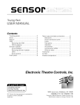
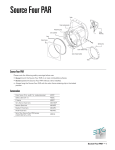
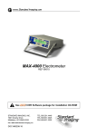
analog
address
FPO
USER
MANUAL
The Analog AddressTM system is a lighting control system that allows you to control
architectural lighting from wall-mounted slider stations. The system can control up to
eight analog channels wired to DMX512 dimmers. Up to eight slider stations may be
installed. The system also includes a processor unit from which you can assign dimmers
to channels and enter other system settings.
In addition to the eight analog channels, the system also includes a panic channel and a
work light channel. Panic and work light channels gives you immediate access to
emergency lights and work lights independent of the eight analog channels. The Analog
Address system includes the following features:
•
•
•
•
•
•
•
•
Eight analog channels
One panic channel
One work light channel
User-definable fade time
Console pile-on and disable modes
Diagnostic tests
One DMX512 input
One DMX512 output
Analog Address hardware components:
•
•
•
•
•
Processor unit
Up to eight slider stations
Up to eight panic stations
Up to eight work light stations
Keyswitch lockout available for all stations
Each slider station includes at least one analog channel potentiometer (pot), a take
control switch, and may include any of the following:
FPO
• Up to eight channel pots
• Local master pot (if more than two channel pots)
• Panic button
Processor unit operation
You can perform the following functions from the processor unit; each is described below.
•
•
•
•
•
•
Assign dimmers to analog, panic and work light channels
Set fade time
Select console pile-on or disable mode
Select DMX512 bypass mode
Set DMX512 protocol termination
Perform diagnostic dimmer tests
Reset
Normal
Edit Down Edit Up
Exit
Menu: PATCH
Enter to proceed
Dim Down Dim Up
Bypass
Normal
Enter
Term. on
Term. off
Processor unit keypad
Assigning dimmers to analog, panic and work light channels
Patch screen
Dim = 512
W= Y P= N
Chan = 1
>1
Dim = Dimmer number
Chan = Channel to which dimmer is assigned
W=
Y if assigned to work light channel, N if
not
P=
Y if assigned to panic channel, N if not
>
Channel editing field
1. Press [Exit] to activate processor unit and display menu.
2. Scroll through menu options on LCD using Dimmer [Up] and [Down] buttons until
Patch appears.
3. Press [Enter] to display Patch screen (see illustration).
4. Select channel number to which you want to assign dimmers by pressing Edit [Up]
and [Down]. Channel numbers one through eight, W (work light), and P (panic) appear
in channel editing field (see illustration).
5. Select dimmer number you wish to assign to channel by pressing Dimmer [Up] and
[Down]. Dimmer numbers stop scrolling when you reach 1; press [Up] or [Down] again
to resume scrolling.
6. Press [Enter] to record dimmer assignment. The screen displays the dimmer’s new
channel assignment.
7. Select next dimmer number to assign to channel, and press [Enter]. Repeat until all
desired dimmers are assigned to channel. You may assign any number of dimmers to
each analog channel, but may assign each dimmer to only one analog channel.
Dimmers included in analog channels may also be assigned to panic and work light
channels.
8. Repeat steps 4 through 6 for next channel. Or, to return to menu, press and hold [Exit].
2 • Analog Address User Manual and Installation Guide
Setting fade time
The fade time is the length of time analog channels take to fade up or down when you
press [Take Control] at a slider station. Fade time applies to all analog channels and the
work light channel. Panic channel turns on instantly. Follow these steps to set fade time:
1. Press [Exit] to display menu.
2. Scroll through menu options on LCD using Dimmer [Up] and [Down] until Fade Time
appears.
Fade time screen
Fade Time =
0:04
EXIT to return
3. Press [Enter] to display the Fade Time screen (see illustration).
4. Press Edit [Up] and [Down] to set the desired fade time. You may enter a fade time
between 0:00 seconds and 5:59 minutes.
5. Press and hold [Exit] to save selection and return to menu.
Selecting console pile-on or disable mode
If you have a lighting control console wired into the Analog Address system, you can
choose whether or not the console can control dimmers included in analog channels.
Two console control options are available: pile-on and disable. If you select pile-on,
the console is able to control all dimmers included in Analog Address channels; the
highest setting between the console and Analog Address establishes active levels. If you
select disable, the console is not able to control any dimmers included in analog or panic
channels; the console can still control dimmers included in only the work light channel. In
disable mode, console controls all dimmers not included in Analog Address analog or
panic channels.
To select console control mode, follow these steps:
1. Press [Exit] to display menu.
Console mode screen
Console = Pile On
2. Scroll through menu options on LCD using Dimmer [Up] and [Down] until Console
appears.
3. Press [Enter] to display the Console mode screen (see illustration).
EXIT to return
4. Press Edit [Up] and [Down] to select pile-on or disable.
5. Press [Exit] to save selection and return to menu.
Selecting bypass mode
The bypass switch on the processor unit allows you to disable the Analog Address
system, and to permit DMX512 data to pass directly from the console to the dimmers. You
may choose to use bypass if you want only the console to control dimmers, or if the
Analog Address system malfunctions.
To enter bypass mode, set bypass switch to Bypass. To resume normal operation, set
bypass switch to Normal.
Analog Address User Manual and Installation Guide • 3
Selecting DMX termination or normal modes
The terminate switch on the processor unit terminates a DMX512 signal
from a remote control console. The processor unit combines the incoming
DMX512 data with the Analog Address data, and generates a new
DMX512 signal.
The Analog Address system is normally the last receiver on a DMX512 data
stream. If so, set the Termination switch to Terminate on. If your Analog
Address system is not the last receiver, set the switch to Terminate off.
Performing diagnostic tests
Three diagnostic tests are available from the processor unit: Test one, Test
all and Monitor.
Test one and Test all
Allow you to set one or all dimmers at a specific output level directly from
the processor unit.
Monitor
Displays which control station currently has control, if panic and work light
channels are active, and if the processor unit is receiving data from a
control console. Monitor also displays current output levels for all analog
channels.
To perform diagnostic tests, follow these steps:
1. Press [Exit] to display menu.
2. Scroll through menu options on LCD using Dimmer [Up] and [Down]
until test name appears, Test one, Test all or Monitor.
Test one screen
3. Press [Enter] and hold until LCD displays test screen.
Dimmer = 512
4. Test one:
Press Dimmer [Up] and [Down] to select desired dimmer number.
Level = FF
Test all screen
All dimmers
Level = FF
Press Edit [Up] and [Down] to select dimmer output level. Or, to set
dimmer at 100 percent, press [Enter] , Edit [Up]. To set dimmer at 0
percent, press [Enter], Edit [Down]. Press [Enter] again to return to the
menu.
Test all:
Test allows you to control output of all dimmers. When you enter Test
all, Analog Address turns all dimmers off until you enter an output
level .
Press Edit [Up] and [Down] to select output level.
4 • Analog Address User Manual and Installation Guide
Monitor test screen
T=1
P=Y
W=N
D=Y
909075FF 00000000
Monitor:
When in Monitor test, the following information appears (see illustration).
T=
P=
W=
D=
(Take Control) indicates which control station currently has control
of channels.
(Panic) indicates if panic channel is active (Y for yes, N for no).
(Work light) indicates if work light channel is active (Y for yes, N for
no).
(Data) indicates if the control panel is receiving data from a console
(Y for yes, N for no).
The bottom row of numbers displays the level that each channel is
currently outputting. The first two digits indicate channel 1’s output level;
the third and fourth digits indicate channel 2’s output level, etc. If channel
output is 100 percent, the level digits read FF.
In the illustration above, slider station 1 has control; the panic channel is
active; the work light channel is not; and the processor unit is receiving data
from a console. Channels 1 and 2 are outputting at 90 percent, channel 3 at
75, channel 4 at 100 percent, and the remaining channels are off.
Slider stations
Take
control
Panic
10
9
8
7
6
5
4
3
2
1
0
10
9
8
7
6
5
4
3
2
1
0
10
9
8
7
6
5
4
3
2
1
0
10
9
8
7
6
5
4
3
2
1
0
10
9
8
7
6
5
4
3
2
1
0
Five channel slider station with panic switch
Slider stations include from one to eight channel pots and a take control switch.
If the station has three or more channel pots, a local master is also included on
the station. Slider stations may also include an integral panic switch. All slider
station controls are described below.
[Take Control]
Press [Take Control] to activate a slider station and fade channels to the levels
set on station's channel pots; all other channels fade out. Only one control
station can have control of channels at a time. The last [Take Control] pressed
determines which control station is active. Channels cross fade in fade time set
on processor unit (see page 3).
When station is active, a green LED on [Take Control] is illuminated. When
station is inactive, an amber LED is illuminated.
Channel potentiometers
Channel pots control channel output levels. You can change output levels before
or after pressing [Take Control]. Printed scale next to each pot displays output
percentage divided by 10. For example, channel outputs at 50 percent when you
set pot to 5.
Master
Master pot determines output percentage of all channel pots at the control
station. For example, if master is set at 5 (50 percent), all station channels output
at 50 percent of their current settings. Master potentiometers are provided on all
control stations with three or more channel pots.
[Panic]
[Panic] sets panic channel to full intensity instantly. Press [Panic] again to turn
panic channel off. Analog channel levels are not affected by panic channel.
Analog Address User Manual and Installation Guide • 5
Panic/work light stations
Panic station
Panic station may have either a pushbutton switch or a keyswitch. For pushbutton
stations, press [Panic] to switch panic channel on. For keyswitch stations, insert key and
turn one quarter turn and back to original position. Panic channel switches to full intensity
immediately (fade time is always 0:00 seconds). To switch panic channel off, press
[Panic] or turn panic key at any panic station. Panic station LED is amber when panic
channel is not active; LED is green when panic is active.
Panic station
Work light station
To switch work light channel on, press [Work light]. Channel fades to full intensity over
fade time set for analog channels. To fade out work light channel, press [Work light] at
any work light station. Work light station LED is amber when channel is not active; LED is
green when it is active.
Keyswitch
Keyswitch stations allow you to disable an associated slider, panic or work light station.
When keyswitch is set Off (amber LED illuminated), associated station is disabled. When
set On (green LED illuminated), associated station operates normally.
Keyswitch station
Electronic Theatre Controls, Inc.
3030 Laura Lane
Middleton, WI 53562
Phone 608/831- 4116 FAX 608/836-1736
Copyright 1992 Electronic Theatre Controls, Inc.
6 • Analog Address User Manual and Installation Guide
FPO