1
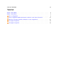
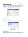
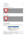
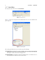
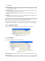
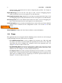
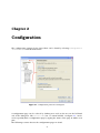
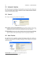
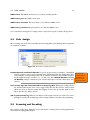
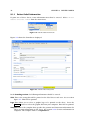
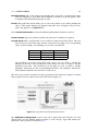
BioBank2 Java Client User Manual
Prepared for the Canadian BioSample Repository
by the Alberta Ingenuity Centre for Machine Learning
July 25, 2011
ii
Contents
1 Overview
1
1.1 Main Menu . . . . . . . . . . . . . . . . . . . . . . . . . . . . . . . . . . . . . .
3
1.1.1 Server Menu . . . . . . . . . . . . . . . . . . . . . . . . . . . . . . . . .
3
1.1.2 Administration Menu . . . . . . . . . . . . . . . . . . . . . . . . . . . .
4
1.1.3 Processing Menu . . . . . . . . . . . . . . . . . . . . . . . . . . . . . . .
4
1.1.4 View Menu . . . . . . . . . . . . . . . . . . . . . . . . . . . . . . . . . .
4
1.1.5 Print Menu . . . . . . . . . . . . . . . . . . . . . . . . . . . . . . . . . .
5
1.1.6 Scanner Menu . . . . . . . . . . . . . . . . . . . . . . . . . . . . . . . .
5
1.1.7 Search Menu . . . . . . . . . . . . . . . . . . . . . . . . . . . . . . . . .
6
1.1.8 Configuration Menu . . . . . . . . . . . . . . . . . . . . . . . . . . . . .
7
1.1.9 Help Menu
. . . . . . . . . . . . . . . . . . . . . . . . . . . . . . . . . .
7
. . . . . . . . . . . . . . . . . . . . . . . . . . . . . . . . . . . . . . . . .
8
1.2 Views
2 Configuration
9
2.1 Automatic Updates
. . . . . . . . . . . . . . . . . . . . . . . . . . . . . . . . .
10
2.2 General . . . . . . . . . . . . . . . . . . . . . . . . . . . . . . . . . . . . . . . .
10
2.3 Issue Tracker . . . . . . . . . . . . . . . . . . . . . . . . . . . . . . . . . . . . .
10
2.4 Link Assign
. . . . . . . . . . . . . . . . . . . . . . . . . . . . . . . . . . . . .
11
2.5 Scanning and Decoding . . . . . . . . . . . . . . . . . . . . . . . . . . . . . . .
11
2.5.1 Decoding Parameters . . . . . . . . . . . . . . . . . . . . . . . . . . . .
12
2.5.2 Decoding Profiles . . . . . . . . . . . . . . . . . . . . . . . . . . . . . . .
13
2.5.3 Plate Positions . . . . . . . . . . . . . . . . . . . . . . . . . . . . . . . .
15
2.5.4 Plate Barcodes . . . . . . . . . . . . . . . . . . . . . . . . . . . . . . . .
18
2.6 Servers
. . . . . . . . . . . . . . . . . . . . . . . . . . . . . . . . . . . . . . . .
3 Patient Processing
18
21
3.1 Shipment . . . . . . . . . . . . . . . . . . . . . . . . . . . . . . . . . . . . . . .
21
3.2 Patient Visit . . . . . . . . . . . . . . . . . . . . . . . . . . . . . . . . . . . . . .
21
3.3 Scan Link . . . . . . . . . . . . . . . . . . . . . . . . . . . . . . . . . . . . . . .
21
3.4 Scan Assign . . . . . . . . . . . . . . . . . . . . . . . . . . . . . . . . . . . . . .
21
3.5 Cabinet Link and Assign . . . . . . . . . . . . . . . . . . . . . . . . . . . . . .
21
iii
iv
CONTENTS
3.6 Patient Merging . . . . . . . . . . . . . . . . . . . . . . . . . . . . . . . . . . . .
21
4 Sample Order Processing
23
5 Dispatch
25
5.1 Configure a Site for Sending Dispatches . . . . . . . . . . . . . . . . . . . . .
25
5.2 Remove Dispatch Configuration for a Site . . . . . . . . . . . . . . . . . . . .
26
5.3 Sending a Dispatch . . . . . . . . . . . . . . . . . . . . . . . . . . . . . . . . .
27
5.4 Receiving a Dispatch
. . . . . . . . . . . . . . . . . . . . . . . . . . . . . . . .
29
5.5 Dispatch Never Arrives at Destination Site . . . . . . . . . . . . . . . . . . . .
29
5.6 Dispatches with Missing Aliquots . . . . . . . . . . . . . . . . . . . . . . . . .
29
5.7 Dispatch with Extra Aliquots . . . . . . . . . . . . . . . . . . . . . . . . . . . .
29
6 Administration
31
6.1 Repository Sites . . . . . . . . . . . . . . . . . . . . . . . . . . . . . . . . . . .
31
6.2 Clinics . . . . . . . . . . . . . . . . . . . . . . . . . . . . . . . . . . . . . . . . .
31
6.3 Studies . . . . . . . . . . . . . . . . . . . . . . . . . . . . . . . . . . . . . . . .
31
6.4 Container Types . . . . . . . . . . . . . . . . . . . . . . . . . . . . . . . . . . .
31
6.5 Containers . . . . . . . . . . . . . . . . . . . . . . . . . . . . . . . . . . . . . .
31
6.6 Moving Samples Between Containers . . . . . . . . . . . . . . . . . . . . . . .
31
6.7 Sample Types . . . . . . . . . . . . . . . . . . . . . . . . . . . . . . . . . . . . .
31
6.8 Source Vessels . . . . . . . . . . . . . . . . . . . . . . . . . . . . . . . . . . . .
31
6.9 Shipping Methods . . . . . . . . . . . . . . . . . . . . . . . . . . . . . . . . . .
31
6.10 Activity Status . . . . . . . . . . . . . . . . . . . . . . . . . . . . . . . . . . . .
31
6.11 User Administration . . . . . . . . . . . . . . . . . . . . . . . . . . . . . . . . .
31
6.11.1Adding Users . . . . . . . . . . . . . . . . . . . . . . . . . . . . . . . . .
31
6.11.2Editing Users . . . . . . . . . . . . . . . . . . . . . . . . . . . . . . . . .
33
6.11.3Password Change . . . . . . . . . . . . . . . . . . . . . . . . . . . . . .
33
7 Reports
35
7.1 Logging . . . . . . . . . . . . . . . . . . . . . . . . . . . . . . . . . . . . . . . .
35
8 Error Reporting
37
9 Printer Labels
39
9.1 Patient Labels
. . . . . . . . . . . . . . . . . . . . . . . . . . . . . . . . . . . .
39
9.1.1 Patient Label Information . . . . . . . . . . . . . . . . . . . . . . . . . .
40
9.1.2 Label Templates . . . . . . . . . . . . . . . . . . . . . . . . . . . . . . .
42
9.2 Advanced Usage - Jasper Templates . . . . . . . . . . . . . . . . . . . . . . .
43
List of Figures
1.1 The Java Client’s main window. . . . . . . . . . . . . . . . . . . . . . . . . . .
2
1.2 Server menu. . . . . . . . . . . . . . . . . . . . . . . . . . . . . . . . . . . . . .
3
1.3 Administration menu. . . . . . . . . . . . . . . . . . . . . . . . . . . . . . . . .
4
1.4 Processing menu. . . . . . . . . . . . . . . . . . . . . . . . . . . . . . . . . . .
4
1.5 Scanner menu. . . . . . . . . . . . . . . . . . . . . . . . . . . . . . . . . . . . .
5
1.6 Search menu. . . . . . . . . . . . . . . . . . . . . . . . . . . . . . . . . . . . . .
6
1.7 Search panel. . . . . . . . . . . . . . . . . . . . . . . . . . . . . . . . . . . . . .
6
1.8 Configuration menu.
. . . . . . . . . . . . . . . . . . . . . . . . . . . . . . . .
7
1.9 Help menu. . . . . . . . . . . . . . . . . . . . . . . . . . . . . . . . . . . . . . .
7
2.1 Configuration preferences dialog box. . . . . . . . . . . . . . . . . . . . . . . .
9
2.2 General preferences. . . . . . . . . . . . . . . . . . . . . . . . . . . . . . . . . .
10
2.3 Issue tracker preferences.
. . . . . . . . . . . . . . . . . . . . . . . . . . . . .
10
2.4 Scan link / Assign preferences. . . . . . . . . . . . . . . . . . . . . . . . . . .
11
2.5 Scanning and Decoding preferences. . . . . . . . . . . . . . . . . . . . . . . .
12
2.6 Selecting a scanning source. . . . . . . . . . . . . . . . . . . . . . . . . . . . .
12
2.7 Decoding preferences. . . . . . . . . . . . . . . . . . . . . . . . . . . . . . . . .
13
2.8 Decoding profiles preferences. . . . . . . . . . . . . . . . . . . . . . . . . . . .
14
2.9 Configuring a plate position. . . . . . . . . . . . . . . . . . . . . . . . . . . . .
15
2.10 Sample flatbed scan.
16
. . . . . . . . . . . . . . . . . . . . . . . . . . . . . . . .
2.11 Grid aligned with tubes.
. . . . . . . . . . . . . . . . . . . . . . . . . . . . . .
17
2.12 Plate 2 grid aligned with tubes. . . . . . . . . . . . . . . . . . . . . . . . . . .
17
2.13 Plate barcode preferences. . . . . . . . . . . . . . . . . . . . . . . . . . . . . .
18
2.14 Server preferences.
. . . . . . . . . . . . . . . . . . . . . . . . . . . . . . . . .
18
5.1 Configuring a site for sending dispatches. . . . . . . . . . . . . . . . . . . . .
26
5.2 Configuring the destination site for dispatches. . . . . . . . . . . . . . . . . .
26
5.3 Removing dispatch configuration for a site. . . . . . . . . . . . . . . . . . . .
27
5.4 Creating a new dispatch. . . . . . . . . . . . . . . . . . . . . . . . . . . . . . .
27
5.5 Selecting study and site when creating a dispatch. . . . . . . . . . . . . . . .
28
5.6 Scanning aliquots into a dispatch.
28
. . . . . . . . . . . . . . . . . . . . . . . .
v
vi
LIST OF FIGURES
6.1 Adding a user. . . . . . . . . . . . . . . . . . . . . . . . . . . . . . . . . . . . .
32
6.2 Editing users. . . . . . . . . . . . . . . . . . . . . . . . . . . . . . . . . . . . . .
33
8.1 Sending an error email. . . . . . . . . . . . . . . . . . . . . . . . . . . . . . . .
37
9.1 CBSR Patient Label sheet. . . . . . . . . . . . . . . . . . . . . . . . . . . . . .
39
9.2 Patient Labels menu item. . . . . . . . . . . . . . . . . . . . . . . . . . . . . .
40
9.3 Patient Label entry form. . . . . . . . . . . . . . . . . . . . . . . . . . . . . . .
40
9.4 Top portion of printed patient label sheet. . . . . . . . . . . . . . . . . . . . .
41
9.5 Text printed on each label. . . . . . . . . . . . . . . . . . . . . . . . . . . . . .
42
9.6 Label templates form. . . . . . . . . . . . . . . . . . . . . . . . . . . . . . . . .
42
LIST OF FIGURES
vii
Todo list
Figure: View Menu . . . . . . . . . . . . . . . . . . . . . . . . . . . . . . . . . . . . . .
5
Figure: Print Menu . . . . . . . . . . . . . . . . . . . . . . . . . . . . . . . . . . . . . .
5
o Are we using this? . . . . . . . . . . . . . . . . . . . . . . . . . . . . . . . . . . . . .
8
o Need an appendix with instructions on how to create these barcodes.
. . . . . .
11
o which user groups should be allowed to create dispatches? . . . . . . . . . . . . .
27
o description requried? . . . . . . . . . . . . . . . . . . . . . . . . . . . . . . . . . . .
32
o description requried? . . . . . . . . . . . . . . . . . . . . . . . . . . . . . . . . . . .
32
viii
LIST OF FIGURES
Chapter 1
Overview
The BioBank2 Java Client is designed to be a client application that connects to a
BioBank2 server that provides services for storing inventory information for biological
samples. More than one client can connect to the server at the same time. The client is
a software application that runs on Microsoft Windows and Linux1 . The client software
is a Java application and requires that a Java JRE or JDK be installed on the computer.
The installation program for the client installs a Java JRE if it is not already present on
the computer.
When running on Microsoft Windows, the client can communicate with scanners that
use either TWAIN2 or WIA3 drivers. Most scanners available on the market provide these
drivers. Therefore, most scanners work with the client software.
The client does not store any inventory information on the computer that it runs on. All
the information is stored on the server. Any client connecting to this server will be able
to see all the information on the server.
Figure 1.1 shows the application’s main window and highlights some of its components.
Window Title Bar The title bar shows the connection information when connected to a
BioBank2 server. The domain name or IP address of the server is displayed and in
square brackets the user name that was used to log in.
Main Menu The main menu allows the user access to the different functions provided by
the software (see section 1.1 for a description of the menu items).
Toolbar Icons The icon buttons in the toolbar allow quick access to often used menu
items. Using the mouse, the user can hover over the icon button and after 2 seconds
a tooltip is displayed describing what the button is for and if applicable the keyboard
shortcut. Note that there is an icon toolbar under the Main Menu and another
grouped with the tree view.
Tree View The tree view shown here is for the Administration View. The application uses
tree views in the Administration View and Processing View (see section 1.2). Tree
view shows nodes in a hierarchical structure. If a node has children, a plus symbol
is displayed next to the node. When the symbol is pressed the node will expand to
show its’ child nodes. Sometimes, operations can be performed on certain nodes in
the tree by right clicking with the mouse on the node.
1 The
scanner cannot be used when using the application on Linux.
2 http://en.wikipedia.org/wiki/TWAIN
3 http://en.wikipedia.org/wiki/Windows_Image_Acquisition
1
2
CHAPTER 1. OVERVIEW
Status Bar The status bar is used to display the current state of the application. It is
usually updated after the user has completed a task.
Figure 1.1: The Java Client’s main window.
1.1. MAIN MENU
1.1
1.1.1
3
Main Menu
Server Menu
The Server main menu item allows the user to login or logout from a server and to quit
the application.
Figure 1.2: Server menu.
The items under the Server main menu item are as follows:
Login Allows the user to login to a BioBank2 server. On startup and when logged out
this menu item is enabled. When logged into a server this menu item is disabled.
Also, the Ctrl + L keyboard short cut can be used to perform this function.
Logout Allows the user to log out and close the connection to a BioBank2 server. On
startup this menu item is disabled. The item is enabled only when the user has
succesfully logged in to a BioBank2 server. Also, the Ctrl + Shift + L keyboard
short cut can be used to perform this function.
Quit Shuts down the application. Also, the Ctrl + Q keyboard short cut can be used
to perform this function.
4
CHAPTER 1. OVERVIEW
1.1.2
Administration Menu
The items under the Administration menu allow the user to perform administration tasks
such as: add repository sites, clinics, studies, container types and containers. Global
information such as Sample Types, Source Vessels, Shipping methods can also be edited.
Adding, Editing users and changing user passwords is also available.
These functions are discussed in detail in Chapter 6.
Figure 1.3: Administration menu.
1.1.3
Processing Menu
The Processing main menu item provides access to the patient processing functions.
These functions are the most often used functions on a day to day basis. Please refer
to Chapter 3 for more details.
Figure 1.4: Processing menu.
1.1.4
View Menu
This menu allows the user to change to a different view. The views allow the user to focus
on different activities such as:
• Administration
1.1. MAIN MENU
5
• Sample Processing
• Inventory Reports
• Activity Logs
See section 1.2 for more information on views.
Missing
figure
1.1.5
View Menu
Print Menu
Missing
figure
1.1.6
Print Menu
Scanner Menu
These functions are for testing the scanning and decoding parameters in the preferences
(see section 2.5).
Figure 1.5: Scanner menu.
Scan Plate Once the scanning regions have been assigned, use this menu item to view
the image that will be scanned for the plates that were defined.
Decode Plate Once the decoding parameters have been changed, use this menu item to
see how well the decoding performs.
6
1.1.7
CHAPTER 1. OVERVIEW
Search Menu
The only item under this menu is the Search Panel.
Figure 1.6: Search menu.
Figure 1.7 shows the search panel in the Adminstration view. It is also available in the
processing view.
Figure 1.7: Search panel.
The search panel allows the user to search for any of the following:
An inventory ID each aliquot has a unique identifier referred to as the inventory ID. This
is the decoded value of the 2D barcode for NUNC tubes, the 1D barcode for hair and
FTA aliquots, and the 1D barcode for Axygen tubes.
An aliquot Position each aliquot is stored in a unique position. For NUNC tubes it is
the well position pre appended with the pallet’s label.
1.1. MAIN MENU
7
Non-active aliquots Aliquots that have been removed from the inventory are assigned a
Non Active activity status. When this search is used the list of all aliquots marked
as non active is returned.
A container label Each container in the inventory has a position label. The label uses
the labeling scheme defined by the parent label.
A container’s product barcode Each container in the system has a unique product barcode.
A worksheet Each patient visit has a unique corresponding worksheet in paper form. A
patient visit can be searched for using this ID.
When an item is searched for the application will: inform you how many items were found
if there are more than one, or open up a form displaying the information for the item. If
more than one item is found then a form is opened up for each item.
Fox example when searching for an inventory id the Aliquot View Form is displayed for
the aliquot. When searching for a container label, the Container view form is displayed.
1.1.8
Configuration Menu
This menu only contains the preferences item. See Chapter 2 for more details.
Figure 1.8: Configuration menu.
1.1.9
Help Menu
The help menu provides access to several functions.
Figure 1.9: Help menu.
Keyboard Shortcuts displays the functions associated with all the keyboard shortcuts.
Send Error Mail if the user encounters a software error, he / she can send an email
to the software design team. By using this function the error log information is
8
CHAPTER 1. OVERVIEW
attached to the email and aids the team in diagnosing the problem. See chapter 8
for more information.
Export Error Logs Used to save the error logs to a file. Used for debugging purposes
only and normal users are not required to use this function.
Show Application Error Logs Displays the error logs in a window inside the client. Used
for debugging purposes only and normal users are not required to use this function.
Reset Perspective Resets the window layout inside the client. Used for debugging purposes only and normal users are not required to use this function.
Check for Updates Used to check and download new version of the java client. Software
updates can be scheduled in the configuration section. See section 2.1 for more
details.
Are we using
this?
Install New Software
About BioBank2 Displays the Java Clients software version information.
1.2
Views
The application has been designed with the following views to aid the user in focusing on
a particular high level task. The views are as follows:
• The Administration View is used to configure the repository site. This deals with
the studies and clinics associated with the repository sites on the server. Also the
view allows the user to configure the containers used by the repository sites. See
Chapter 6 for more details on this view.
• The Processing View deals with accepting patient samples and storing the derived
aliquots in a repository site. As well, dispatching samples between sites can be done
with this view. See Chapter 3 for more details on this view.
• The Reports View deals with querying information form the database. Pre-defined
reports can be executed in this view as well as allowing the user to create his / her
own reports. In addition, the user activity logs can also be queried in this view. See
Chapter 7 for more details on this view.
Chapter 2
Configuration
The configuration settings for the Java Client can be found by selecting Configuration
→ Preferences from the main menu.
Figure 2.1: Configuration preferences dialog box.
A configuration page can be selected by clicking on a node on the tree on the left hand
side of the dialog box. The filter text box, see arrow labelled 1 in figure 2.1, can be
used to quickly find a configuration page by typing the name of the page in whole or in
part.
The following sections discuss the configuration pages in detail.
9
10
2.1
CHAPTER 2. CONFIGURATION
Automatic Updates
The Java Client has the capability of detecting when a new version of the software has
been made available by the software design team. The settings on this page allow the
user to specify when updates will be searched for, when to download them, and how to
notify the user when they are found.
2.2
General
The settings on this page are general to the application.
Figure 2.2: General preferences.
Show software version in main window title the Java Client’s software version can be
displayed in the window’s title bar by checking this box.Note that this option is only
required by technicians when they are testing new versions of the software.
Show heap status the heap status can be displayed in the main window by checking this
box. The heap status gives an indication of the memory used by the application. This
option is in place for the software designers and is not required for normal use.
2.3
Issue Tracker
The application has the capability of sending Problem Report emails to the software design team1 . The error emails have application state information attached to aid team in
resolving potential problems. The settings on this page are the settings used to send the
emails to the team.
Figure 2.3: Issue tracker preferences.
Tracker email The email address to send problem reports to.
1 Help
-> Send Error Email from the main menu
2.4. LINK ASSIGN
11
SMTP server The SMTP mail server to use when sending emails.
SMTP server port The SMTP server port.
SMTP server username The user name to use with the SMTP server.
SMTP server password The password to use with the SMTP server.
Users should not modify these settings unless requested to by the software design team.
2.4
Link Assign
These settings are used when scanning and decoding pallets and linking them to patients
or container locations.
Figure 2.4: Scan link / Assign preferences.
Confirm Barcode and Cancel Barcode To speed up processing of samples, a handheld
barcode scanner can be used to quickly enter information into the application. Barcodes with the corresponding words can be printed and then scanned when required
by the application (See sections 3.3, 3.4 and 3.5). The Confirm Barcode and Cancel Barcode settings contain the text encoded into these barcodes when they were
created.
Save activity logs into a file and Path for activity logs files When processing patients,
the actions taken by the user can be logged and saved to files on disc. This section
allows the user to activate saving this logging to disc and specify the path on disc
where the files are will be saved.
Ask to print activity log When a scan link or scan assign session is over the user can be
prompted to print the activity logs. This setting enables or disables the prompting.
2.5
Scanning and Decoding
The settings on this page allow the user to specify the scanning and decoding parameters
used when decoding pallet images.
Need an appendix with instructions on
how to create
these barcodes.
12
CHAPTER 2. CONFIGURATION
Figure 2.5: Scanning and Decoding preferences.
Select Scanner This button is used to select the scanner that will be used to scan 96
well pallets. The dialog box shown in figure 2.6 is shown when the button is pressed.
Figure 2.6: Selecting a scanning source.
Driver Type The type of driver that was selected when the Select Scanner button was
pressed. Normally, the application will attempt to determine the driver type as soon
as the user makes the selection, but sometimes the application does not select the
correct type. Use the check boxes here to override what the application selected if it
was incorrect.
DPI The Dots per Inch used by the scanner for scanning images. For best results use 600
DPI.
Brightness The brightness setting to be used when scanning images. This parameter
does not work on Hewlett-Packard scanners when using the WIA based driver.
Contrast The contrast setting to be used when scanning images. This parameter does
not work on Hewlett-Packard scanners when using the WIA based driver.
2.5.1
Decoding Parameters
On the preferences dialog window, if there is a "plus" symbol next to the Scanning and
Decoding node, press it to expand the sub tree.
These settings control how the software decodes the sample tubes imprinted with DataMatrix 2D barcodes.
2.5. SCANNING AND DECODING
13
Figure 2.7: Decoding preferences.
Decode Library Debug Level The decoding software library can output debugging information to a log file. When this value is zero there is no debugging information
stored in the log file. Possible values are 0 through 9. The higher the value the more
detailed the debugging information.
Decode Edge Threshold Set the minimum edge threshold as a percentage of maximum.
For example, an edge between a pure white and pure black pixel would have an
intensity of 100. Edges with intensities below the indicated threshold will be ignored
by the decoding process. Lowering the threshold will increase the amount of work
to be done, but may be necessary for low contrast or blurry images. The default and
recommended value is 5.
Decode Square Deviation Maximum deviation (in degrees) from squareness between adjacent barcode sides. The default and recommended value is N=15 and is meant for
scanned images. Barcode regions found with corners <(90-N) or >(90+N) will be ignored by the decoder.
Decode Corrections The number of corrections to make while decoding. The default and
recommended value is 10.
Decode Scan Gap The scan grid gap size in inches. The default and recommended value
is 0.085.
Decode Cell Distance The distance in inches between tubes.The default and recommended value is 0.345 for NUNC pallets.
2.5.2
Decoding Profiles
On the preferences dialog window, if there is a "plus" symbol next to the Scanning and
Decoding node, press it to expand the sub tree.
This page allows the user to define Decoding Profiles. These profiles allow the user define
a sub set of tubes to decoded when an image of a pallet is scanned. Scanning profiles can
be used during scan link and scan assign (see sections 3.3 and 3.4).
14
CHAPTER 2. CONFIGURATION
Figure 2.8: Decoding profiles preferences.
For example: the user may wish to only decode every other row on a pallet. Once the
profile is created it can be used at scan link and scan assign time and only the cells
activated in the profile will be decoded. If 2D barcodes are found in the cells not active in
the profile, the user will be given a warning message.
To create a new profile follow these instructions:
1. Press the Add... button. A dialog box pops up requesting a name for the new profile.
Enter an appropriate name and press the OK button.
2. Now select each cell that should be part of the profile (see cells with a checkmark in
Figure 2.8). When done selecting cells press the Apply button.
2.5. SCANNING AND DECODING
2.5.3
15
Plate Positions
On the preferences dialog window, if there is a "plus" symbol next to the Scanning and
Decoding node, press it to expand the sub tree.
Figure 2.9: Configuring a plate position.
To define a pallet scanning region do the following:
1. Place a pallet that contains tubes on the flatbed scanner. Ensure the top edge of the
pallet is touching the top of the scanning region, and the right edge of the pallet is
touching the right margin. Ensure the 12 columns are vertical and the 8 rows are
horizontal.
2. Select the plate region you are going to define. If it is the first select Plate 1 Position.
3. Click on the Enable box.
16
CHAPTER 2. CONFIGURATION
4. Press the Scan button. Now wait for the scanner to scan the entire flatbed.
Figure 2.10: Sample flatbed scan.
5. Once the scan is done, you will see something similar to Figure 2.10. The image
shown on the right hand side is the image taken by the scanner and superimposed
is a grid with 8 rows and 12 columns. The cell coloured in cyan should correspond
to tube in row A and column 1.
6. Under orientation select "Landscape".
7. You can adjust the size of the grid using the mouse. If you move the mouse to
one of the corners or one of the edges you can resize the grid by holding down the
left button on the mouse. The whole grid can be moved by pressing the left mouse
button while hovering inside the grid.
2.5. SCANNING AND DECODING
17
8. Once the grid cells are aligned with each tube press the OK button (see Figure
2.11). The wheel on the mouse can be used to make the cells smaller or bigger (this
is referred to as the Cell Gap).
Figure 2.11: Grid aligned with tubes.
9. Repeat from step 2 to define any more pallet scanning regions.
10. Usually only one pallet scanning region is required for normal operation of the software.
Figure 2.12 shows an example of how Plate 2 can be defined. Here Plate 2 is touching the
top and the left margin of the of the flatbed region. The plate on the left of the image is
where Plate 1 is defined.
Figure 2.12: Plate 2 grid aligned with tubes.
Note that cell A1 should be at the Top Left when configuring a plate in Landscape orientation and Top Right when in Portrait orientation when looking down at the scanner’s
flatbed.
18
CHAPTER 2. CONFIGURATION
To test if your configuration will yield valid decodes use the Scanner -> Decode Plate
from the main menu.
2.5.4
Plate Barcodes
To speed up processing of samples, a handheld barcode scanner can be used to quickly
enter information into the application. Barcodes with the corresponding words can be
printed and then scanned when required by the application (See sections 3.3 and 3.4).
The Plate x barcode settings contain the text encoded into these barcodes when they
were created.
Figure 2.13: Plate barcode preferences.
2.6
Servers
This page contains a list of BioBank2 servers that the Java Client connects to on a regular
basis. This list is used in the login dialog box to aid the user to quickly select a server.
New servers can be added to this list by pressing the New button. Only the domain
name or IP address for the server is required.
Figure 2.14: Server preferences.
Previously entered servers can also be edited with the Edit button if a spelling mistake
was made.
2.6. SERVERS
19
The order in the list can be rearranged with the Up and Down buttons to put more
frequently accessed servers at the beginning of the list.
20
CHAPTER 2. CONFIGURATION
Chapter 3
Patient Processing
3.1
Shipment
3.2
Patient Visit
3.3
Scan Link
3.4
Scan Assign
3.5
Cabinet Link and Assign
3.6
Patient Merging
21
22
CHAPTER 3. PATIENT PROCESSING
Chapter 4
Sample Order Processing
23
24
CHAPTER 4. SAMPLE ORDER PROCESSING
Chapter 5
Dispatch
The Dispatch feature is used to record the shipping of a set of patient sample aliquots
between two repository sites where all patients and aliquots belong to a single study.
Aliquots from multiple patients may be included in a dispatch.
To use the dispatch feature in BioBank2 the two sites and the study involved must first
be configured (see section 5.1 for instructions).
Prior to sending a dispatch, the administrator of the sending site must create a dispatch
entry that records the aliquots that are part of the shipment. After the entry is created
and the dispatch is ready to be sent, the administrator must mark the entry as Sent. At
this point BioBank2 displays the dispatch entry as In Transit (see section 5.3).
Sites that wish to send dispatches can only send aliquots that have been scan assigned
to container positions. Aliquots without a position are not allowed in a dispatch.
When receiving a dispatch, a technician with the appropriate role must Receive and Process the dispatch entry in BioBank2. Only entries marked as In Transit can be received
and processed. A technician has the option of only marking an entry as received and
then process it at a later time. Processing of a dispatch entry involves confirming that
the aliquots recorded as sent are actually received. See section 5.4 for instructions. The
following errors can happen when sending a dispatch:
• The shipment never arrives at the destination site.
• One or more aliquots marked as sent are not actually received at the receiving site,
• One or more aliquots never marked as sent are received at the receiving site.
Please see sections 5.5, 5.6 and 5.7 for instructions on how to deal with these cases.
If a repository site no longer sends dispatches, the instructions to remove the dispatch
information is given in section 5.2.
5.1
Configure a Site for Sending Dispatches
1. Log into the BioBank2 Java Client as a user in the Website Administrator group.
2. From the Administration view, edit the site that is to send dispatches.
3. Click on Add Dispatch Relation (see Figure 5.1).
25
26
CHAPTER 5. DISPATCH
Figure 5.1: Configuring a site for sending dispatches.
4. From the dialog box the pops up, select the study associated with the site and the
destination site for the shipments (see Figure 5.2) and press the OK button. Use the
button with an arrow pointing to the right to move a site from the Available Sites
box to the Selected Destination Sites box.
Figure 5.2: Configuring the destination site for dispatches.
5. If there are more studies that dispatch from this site go to step 3.
5.2
Remove Dispatch Configuration for a Site
1. Log into the BioBank2 Java Client as a user in the Website Administrator group.
2. From the Administration tree view, right click on the site that will no longer send
dispatches and select Edit Site.
5.3. SENDING A DISPATCH
27
3. In the entry form that opens up, right click on the study / site you wish to remove
the configuration for and select Delete.
Figure 5.3: Removing dispatch configuration for a site.
5.3
Sending a Dispatch
1. Log into the BioBank2 Java Client as a user in the Website Administrator group.
2. In the Working Site pull down, select the site that is to send the dispatch.
3. Using the main menu or the toolbar icon select Dispatch view.
4. Select Add Dispatch from the Dispatch Shipments sub menu or from the toolbar icon.
Figure 5.4: Creating a new dispatch.
5. Select the study and receiver site the dispatch aliquots are for. If there is a single
study and / or a single receiver site they will be already selected.
which user
groups should
be allowed
to create dispatches?
28
CHAPTER 5. DISPATCH
Figure 5.5: Selecting study and site when creating a dispatch.
6. Press the open scan dialog button to scan assign aliquots into the dispatch and the
following dialog box is displayed.
Figure 5.6: Scanning aliquots into a dispatch.
7. Enter the pallet’s product barcode or click the new pallet 1 check box, then the plate
number for where the pallet has been placed on the flatbed scanner and then press
the Launch Scan button.
1 The new pallet check box is used when aliquots are moved from their original pallet to a new pallet to be
used for the actual shipping.
5.4. RECEIVING A DISPATCH
5.4
Receiving a Dispatch
5.5
Dispatch Never Arrives at Destination Site
5.6
Dispatches with Missing Aliquots
5.7
Dispatch with Extra Aliquots
29
30
CHAPTER 5. DISPATCH
Chapter 6
Administration
6.1
Repository Sites
6.2
Clinics
6.3
Studies
6.4
Container Types
6.5
Containers
6.6
Moving Samples Between Containers
6.7
Sample Types
6.8
Source Vessels
6.9
Shipping Methods
6.10
Activity Status
6.11
User Administration
6.11.1
Adding Users
To add a new user select Administration → Add User from the main menu. You will see
the following dialog window pop up. Enter the user’s details and press the OK button.
31
32
CHAPTER 6. ADMINISTRATION
Figure 6.1: Adding a user.
For Available Groups the following exist:
Website Administrator This user type has acces to create any type of object in the system: create repository sites, studies, clinics and containers, etc. This user type can
also edit global data such as sample types, shipment methods, etc. And also create
and edit users.
CBSR Technician Level 1 This user type can view, update, create and delete patients,
shipments, samples, sample types and containers. This user type cannot create
repository sites, studies and clinics.
CBSR Technician Level 2 This user type can view, update and create patients, shipments and samples. This user type cannot create repository sites, studies and clinics.
description requried?
Calgary Administrator .
description reCalgary Technician .
quried?
The password assigned to the new user is temporary. When the user logs in for the first
time, he / she will be asked to enter the temporary password and select a new password.
6.11. USER ADMINISTRATION
6.11.2
33
Editing Users
Figure 6.2: Editing users.
6.11.3
Password Change
34
CHAPTER 6. ADMINISTRATION
Chapter 7
Reports
7.1
Logging
35
36
CHAPTER 7. REPORTS
Chapter 8
Error Reporting
Figure 8.1: Sending an error email.
37
38
CHAPTER 8. ERROR REPORTING
Chapter 9
Printer Labels
The BioBank Java client can be used to print labels to any type of printer. At the moment
only CBSR Patient Labels are supported.
9.1
Patient Labels
Each patient label contains a 1D barcode
for the patient number and a unique 2D
Data Matrix barcode for the specimen ID.
Each specimen ID is unique amongst any
patient labels printed in the past and in
the future. Also, the specimen ID is unique
across patients such that two patients will
never have the same specimen ID.
Figure 9.1 shows a blank CBSR Patient Label sheet. It is a letter sized, 8 12 ” x 11”,
sheet that feeds into any printer.
The regions highlighted in orange are:
1. The title area.
Clinics and sites
can customize their labels by printing
their own title text.
2. The logo region. A custom logo or
graphic can be printed on the label.
3. Patient information section. Up to 3
custom fields can be printed in this
region.
Figure 9.1: CBSR Patient Label sheet.
4. The individual patient labels that
contain a 1D barcode for the patient
number and a 2D barcode for the
specimen ID. There are 32 labels in
total.
39
40
9.1.1
CHAPTER 9. PRINTER LABELS
Patient Label Information
To print one of these sheets, some information must first be entered. Select Printer
Labels → Patient Labels from the main menu.
Figure 9.2: Patient Labels menu item.
Figure 9.3 shows the form that is displayed.
Figure 9.3: Patient Label entry form.
In the branding section, the following information should be entered.
Title This is the string that will be printed in the label sheet’s title area. See area 1 in
figure 9.1. This field is optional.
Logo This allows you to select a graphic logo to be printed on the sheet. Press the
Browse button to select the graphic file from your computer. This field is optional.
Template This is the template that specifies the position and dimension information for
where to print information on the sheet. See section 9.1.2 for more information on
templates. The template name is a required field.
9.1. PATIENT LABELS
41
Intended Printer this is the printer the template was created for. You may have more
than one template to select from. Each template is meant for a specific printer. This
is displayed for informational purposes only.
Printer This pull down menu allows you to select the printer to use when printing the
sheets. This menu displays the printers that have been configured on your computer. The printer is a required field.
In the Patient Information section the following information should be entered.
Patient Number Type the patient’s number into this box. A number is required.
Custom Fields Three custom fields can be enabled to print on the label sheet. The text
box on the left is the field name and the text box on the right is its corresponding
value. In this example, the following are used for custom fields:
Custom Field
1
2
3
Name
Patient Name
PHN
Patient Type
Value
Jonh Doe
5555-5555-5555
Control Patient
The checkboxes to the left of the field name can be used to enable / disable the
printing of the field. The checkboxes in the middle are used to enable / disable
printing of the value. The checkboxes on the right are used to enable / disable
printing a 1D barcode for the corresponding field value. For example a 1D barcode
will be printed with the text John Doe encoded on it.
The above two sections are printed on the top portion of the label sheet. Figure 9.4 show
what is printed for the values entered into the form in figure 9.3.
Figure 9.4: Top portion of printed patient label sheet.
The Additional Configuration section is for text to print under the barcodes on each
patient label. In the example shown in figure 9.3 the text Sp. Type with underscore
characters will be printed as shown in 9.5.
42
CHAPTER 9. PRINTER LABELS
Figure 9.5: Text printed on each label.
To print a sheet of labels you can press the Print button at the top left of the form.
Alternatively, instead of printing a sheet you can export the sheet to a PDF file by pressing
the Export to PDF button.
9.1.2
Label Templates
Select Printer Labels → Label Templates from the main menu to see the form shown
in figure 9.6.
Figure 9.6: Label templates form.
The label template Patient with Source Specimen Label Template is already configured
on the server for all users. This default template tells the software where to print the
information on the label sheet. For your printer, it is possible that the default template
does not print the information at the correct positions. You can create a new template by
copying the default template and adjusting the settings for your printer.
9.2. ADVANCED USAGE - JASPER TEMPLATES
43
You may need to define templates for each printer that your computer can access. To
copy a template select the template you want to copy and press the Copy button. You
can also create a fresh template by pressing the New button. In the future, you may
want to delete an old template that is no longer in use. This can be done by selecting
the template to be deleted and pressing the Delete button. To save your settings to the
template you can press the Confirm button at the top left of the form.
The settings for a template are:
Template Name A descriptive name for the template. It is a good idea to include the
name of the printer the template is intended for.
Jasper Configuration For patient labels you should always select the Patient with Source
Specimens Jasper Template. This template is defined by default on the server. For
more information see section 9.2.
Intended Printer the name of the printer the template is intended for.
Configuration Allows for adjustments to the positions for the items to be printed.
Each 1D and 2D barcode item on the sheet has a horizontal offset, vertical offset,
width and height. All measurements are in millimetres. The Patient Info group corresponds to section 3 in figure 9.1. The Barcodes group corresponds to the 32 patient
labels. The labels are numbered starting at the top left and ending at the bottom right.
Under this group there is a General node that controls the position of the patient 1D
barcode, the specimen ID 2D barcode, and the custom text position for all 32 labels. In
addition, each label can control the position of the same 3 items individually. If values
are entered here they are added to the values in the general group. To move something
to the left then use a negative value.
For example if the general barcode settings are the ones shown in the General node in
the tree in figure 9.6, and the settings for barcode 001 are changed to those shown in
figure 9.6, then the patient barcode is printed 10 mm from the left edge and 7 mm from
the top edge.
Note that width and height is only applicable to 1D and 2D barcodes. For items with the
text Text in the name the widht and the height are ignored.
9.2
Advanced Usage - Jasper Templates
There is no need for the average user to change the Jasper Templates. The Jasper configuration templates feature should only be used by site administrators.
The printing of the information on a patient label sheet is managed by JasperReports. To
print the sheet there is information that must be given to JasperReports for it to print
correctly. This template holds the information and is customized for the patient labels
sheet.
In the future, additional label sheets may be printed by the Java client. Future label
sheets will have their own Jaspser templates.
44
CHAPTER 9. PRINTER LABELS