1
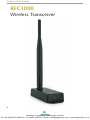
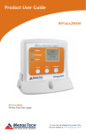
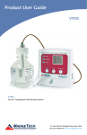
Product User Guide
RFCurrent2000A
RFCurrent2000A
Wireless Current Data Logger
Distributor: LoggerShop Technologies | Dorset
Tel: +44 (0)845 520 0202 Fax: +44 (0)845 520 0203 | Email: [email protected] | www.loggershop.co.uk
Product User Guide
Table of Contents
RFCurrent2000A Data Logger
Quick Start Steps ............................................ 1
Product Overview ........................................... 2
Additional Features & Operation ..................... 3
Mounting Instructions .................................... 4
Product Maintenance...................................... 5
Recalibration ................................................... 5
RMA Instructions.............................................. 5
General Specifications................................... 6-7
RFC1000 Transceiver
Product Overview ........................................... 9
Installation Guide ............................................ 9
Mounting Instruction .................................... 10
Channel Programming.................................. 11
Deployment & Activation............................... 12
General Specifications.................................... 12
Compliance Information................................. 13
Troubleshooting Tips ............. Back Cover
Distributor: LoggerShop Technologies | Dorset
Tel: +44 (0)845 520 0202 Fax: +44 (0)845 520 0203 | Email: [email protected] | www.loggershop.co.uk
Quick Start Steps
Product Operation (Wireless)
1. Install the MadgeTech 4 Software and USB Drivers onto a Windows PC.
2. The RFC1000 interface device comes with a USB cable. Plug one end of the cable into
an available USB port on the PC and plug the opposite end of the cable into the
communication port on the RFC1000.
3. Push and hold the wireless button on the RFCurrent2000A for 5 seconds to activate
wireless communication. The display will confirm “Wireless: ON” and the blue LED will
blink every 15 seconds.
4. Launch the MadgeTech 4 Software. All active MadgeTech Data Loggers that are within
range will automatically appear in the connected devices window. Each data logger in
the list can be identified by serial number (printed on the exterior of the logger).
5. To claim a device, select the desired data logger in the list and click the Claim icon.
6. Select the start method, reading rate and any other parameters appropriate for the
desired data logging application. Once configured, deploy the data logger by clicking
the Start icon.
7. To download data, select the device in the list, click the Stop icon, and then click the
Download icon. A graph will automatically display the data.
Product Operation (Plugged In)
1. Install the MadgeTech 4 Software and USB Drivers onto a Windows PC.
2. Before plugging the data logger in the computer, make sure the wireless setting on
the device is set to “Wireless: OFF”. If wireless mode is on, press and hold the Wireless
button on the device for 5 seconds.
3. The RFCurrent2000A comes with a USB cable. Plug one end of the cable into an
available USB port on the PC and plug the opposite end of the cable into the
communication port on the RFCurrent2000A.
4. Launch the Data Logger Software. The RFCurrent2000A will appear in the connected
devices window indicating the device has been recognized.
5. Select the start method, reading rate and any other parameters appropriate for the
desired data logging application. Once configured, deploy the data logger by clicking
the Start icon.
6. To download data, select the device in the list, click the Stop icon, and then click the
Download icon. A graph will automatically display the data.
1
Distributor: LoggerShop Technologies | Dorset
Tel: +44 (0)845 520 0202 Fax: +44 (0)845 520 0203 | Email: [email protected] | www.loggershop.co.uk
Product User Guide
Product Overview
The RFCurrent2000A is a wireless data logger with display, designed to measure and record
DC current signals. The data logger can connect directly to low-level DC current sources
which makes it ideal for battery usage studies, energy monitoring studies and other DC
current monitoring applications. The RFCurrent2000A can also be interfaced with a wide
range of current output sensors such as flow meters, pH transmitters and more. Through the
software, the device can be programmed with engineering units, which convert the current
readings into a different unit of measure such as flow rate. The engineering unit is available
for display on the LCD screen as well as in the software. The RFCurrent2000A is available in
20mA, 160mA or a 3A measurement range.
The RFCurrent2000A features an LCD screen which provides instant access to the current
reading, minimum, maximum and average statistics. The statistics can be reset through
the keypad of the device, allowing customers to keep track of statistics over certain time
periods. This feature does not erase the data recorded, but only resets the statistics count.
The RFCurrent2000A can be used as a standalone data logger, or used with the RFC1000
wireless transceiver, to transmit data back to a central PC. The RFCurrent2000A transmits
up to 500’ line of sight to the RFC1000 transceiver. Multiple RFC1000’s can be used as
repeaters and transmit up to 1000’ line of sight to other RFC1000’s. This allows the data to
be sent over a greater distance.
Selection Buttons
The logger is designed with 3 direct selection buttons: Scroll, Units and Wireless.
• Scroll: Allows user to scroll through current readings, average stats and device status
information displayed on the LCD Screen.
• Units: Allows user to change displayed units of measurement, A and mA Engineering Units.
• Wireless: Push and hold this button for 5 seconds to activate or deactivate wireless
communication.
• Manual Reset Option: Allows user to manually reset the statistics within the device to 0
without needing to use the Data Logging software. Any data recorded up to that point is recorded and saved.
LED Indicators
• Status: Green LED blinks every 5 seconds to indicate unit is logging.
• Wireless: Blue LED blinks every 15 seconds to indicate unit is operating in wireless mode.
• Alarm: Red LED blinks every 1 second to indicate an alarm condition.
Connecting Information
Port Information
The RFCurrent2000A data logger terminal
ports are located on the bottom of the
device, one positive, one negative and a
ground terminal port.
GND
2
Distributor: LoggerShop Technologies | Dorset
Tel: +44 (0)845 520 0202 Fax: +44 (0)845 520 0203 | Email: [email protected] | www.loggershop.co.uk
RFCurrent2000A
Additional Features and Operation
Alarm Settings/Rules
In the Data Logging Software, alarms can be
created on two levels; in the software itself,
and programmed specifically to the data
logger. Creating alarm rules in the software
allows the user to utilize alarms while
real time recording, and have the added
benefit of features such as e-mail and SMS
notification. An alarm that is programmed
on the data logger will only alert the user
from the device itself, whether that is by a
flashing LED, audible alarm, or local LCD
notification.
Creating a Real time Alarm Rule
1. Within the Device tab in the Data Logging Software, in the Alarms group, click Manage
Rules, then select New.
2. Enter a name in the Rule name box, and select whether notifications will occur when
All conditions are met or Any condition is met.
3. Select the desired conditions to have met before notifications occur, and select which
notifications will occur from the drop down menus.
4. If selecting to receive notifications by email or text message, click Email settings and
make sure the correct info has been entered. Email and text message notifications will
not be received if settings are incorrect.
5. Click OK. The OK button will be disabled if the Rule name box is empty.
Changing the Alarm Settings of a Device
1.In the Connected devices panel, select the RFCurrent2000A device.
2.Click the Properties button under the device tab at the top of the software, and select
the Alarm tab in the Properties window.
3.The High and Low settings indicate reading thresholds at which the alarm becomes active.
4.The Delay setting indicates how long to wait before the alarm becomes active after
passing an alarm threshold.
5.The Use cumulative alarm delay checkbox indicates whether the alarm delay should
reset when reading values fall back within the alarm threshold.
6.Once the alarm is configured appropriately, click Apply to save the settings.
3
Distributor: LoggerShop Technologies | Dorset
Tel: +44 (0)845 520 0202 Fax: +44 (0)845 520 0203 | Email: [email protected] | www.loggershop.co.uk
Product User Guide
Mounting Instructions
The base provided with the RFCurrent2000A can be used in two ways.
• The bottom of the logger snaps in place to use and mount the unit on a table top or
horizontal surface.
• The base can also securely snap to the backside of the logger for wall mounting if desired
(as shown below).
• There are two holes in the base to allow for screws for mounting.
4
Distributor: LoggerShop Technologies | Dorset
Tel: +44 (0)845 520 0202 Fax: +44 (0)845 520 0203 | Email: [email protected] | www.loggershop.co.uk
RFCurrent2000A
Product Maintenance
Battery Replacement
Materials: U9VL-J Battery
1. On the bottom of the enclosure, open the battery compartment by pulling in on the
cover tab.
2. Remove the battery by pulling it from the compartment.
3. Install the new battery, taking note of the polarity.
4. Push the cover closed until it clicks.
Recalibration
Standard recalibration for the RFCurrent2000A-3A are two points, 0A and 1.00A. For
the RFCurrent2000A-20mA, the standard calibration points are 0mA and 25V. For the
RFCurrent2000A-160mA the standard calibration points are 0mA and 100mA.
Recalibration is recommended annually for any data logger; a reminder is automatically
displayed in the software when the device is due.
5
Distributor: LoggerShop Technologies | Dorset
Tel: +44 (0)845 520 0202 Fax: +44 (0)845 520 0203 | Email: [email protected] | www.loggershop.co.uk
Product User Guide
RFCurrent2000A General Specifications
Reading Rate
Memory
Memory Wrap Around
1 reading every second up to 1 reading every 24 hours
32,256 readings
Yes
Start Modes
Immediate Start & Delayed Start
Stop Modes
• Manual through software
• Delayed Stop
• Timed (specific date and time)
Real Time Recording
The device may be used with PC to monitor and record data in real-time
User configurable audible, on-screen, email and text (SMS) alarms.
Alarm
Audible Alarm
Functionality
Alarm Delay: A cumulative alarm delay may be set in which the device
will activate the alarm (via LED) only when the device has recorded a
user specified time duration of data.
1 beep per second for reading alarm above/below threshold
LED Functionality
• Green LED blinks every 10 seconds to indicate unit is logging
• Blue LED blinks every 30 seconds to indicate unit is in wireless mode
• Red LED blinks every 1 second to indicate alarm condition
Password Protection
An optional password may be programmed into the device to restrict access
to configuration options. Data may be read out without the password.
Engineering Units
Native measurement units can be scaled to display measurement units
of another type. This is useful when monitoring voltage outputs from
different types of sensors such as temperature, CO2, flow rate and more.
Calibration
Calibration Date
Battery Type
Battery Life
Data Format
Time Accuracy
Computer Interface
Software
Operating
Environment
Dimensions
Weight
Enclosure Material
Approvals
Digital Calibration through software.
Automatically recorded through the device
Ultralife 9V Lithium included; user replaceable
Approximately 4 years typical for 15 minute reading rate
uA, mA, A
± 1 minute/month
USB to mini USB, 250,000 baud for standalone operation or RFC1000/
RFC1000-CE/RFC1000-IP69K required for wireless operation
XP SP3/Vista/Windows 7/Windows 8 (MadgeTech 4 only)
-20°C to +60°C (-4°F to +140°F) 0% to 95% RH non-condensing
3.3” x 3.5” x 0.95” (82.6mm x 88.9mm x 24.1mm) - Data logger only
4.1 oz (0.2563 lbs)
ABS Plastic
US (FCC), CA (IC), CE, South Korea (KCC)
This device complies with Part 15 of the FCC Rules. Operation is subject to the following two conditions: (1) this device may not cause
harmful interference, and (2) this device must accept any interference received, including interference that may cause undesired operation.
6
To satisfy FCC RF Exposure requirements for mobile and base station transmission devices, a separation distance of 20 cm or more should
be maintained between the antenna of this device and persons during operation. To ensure compliance, operation at closer than this
distance is not recommended. The antenna(s) used for this transmitter must not be co-located or operating in conjunction with any other
antenna or transmitter.
Distributor: LoggerShop Technologies | Dorset
Tel: +44 (0)845 520 0202 Fax: +44 (0)845 520 0203 | Email: [email protected] | www.loggershop.co.uk
RFCurrent2000A
Measurement
Sensor Type
Current Sensing Circuitry
20mA
160mA
3A
-2mA to +30mA
-160mA to +160mA
-3A to +3A
2.5 V
2.5 V
2.5 V
0.0005mA for 20mA
0.01mA for 160mA
0.0001A for 3A
±0.0025mA
±0.01mA
±0.0001A
10 Ω
1Ω
0.02 Ω
±232 mA
for 2 Seconds
±707 mA
for 2 Seconds
±5A for 2 Seconds
Nominal Range
Measurement Range
Maximum Voltage
Between Inputs to
Ground
Measurement Resolution
Calibrated Accuracy
Input Impedance
Absolute Maximum
Current
Input Connection
Analog Conversion Time
Frequency Rejection
Temperature Coefficient
Response Time
Terminal Ports: one positive, one negative and a ground terminal
port.
150 mS
50+60 Hz
< ± 50 ppm/°C typical
0.15 Seconds at Sensor
Wireless
RF Frequency
Band
Receiver Sensitivity
(RFC1000)
2.45GHz IEEE 802.15.4 ultra-low power wireless transceiver with
fully bi-directional communication
ISM band 2.405-2.475 GHz
Operation (channels 11 through 25) @ 250 kbps
-95dBm typical
•
Transmission Distance
(to other RFC1000’s)
•
•
Transmission Distance
(to data loggers)
•
RFC1000
4,000’ max. outdoors - line of sight unobstructed
1,000’ max. indoors - typical urban environment
RFC1000-CE
2,500’ max. outdoors - line of sight unobstructed
700’ max. indoors - typical urban environment
RFC1000-IP69K
4,000’ max. outdoors - line of sight unobstructed
1,000’ max. indoors - typical urban environment
RFC1000, RFC1000-CE & RFC1000-IP69K
2,000’ max. outdoors - line of sight unobstructed
500’ max. indoors - typical urban environment
Battery Warning
WARNING: MAY LEAK, FLAME OR EXPLODE IF DISASSEMBLED, SHORTED, CHARGED, CONNECTED TOGETHER, MIXED WITH
USED OR OTHER BATTERIES, AND/OR EXPOSED TO FIRE/HIGH TEMPERATURE. DISCARD USED BATTERY PROMPTLY, KEEP OUT OF
REACH OF CHILDREN.
Specifications subject to change.
7
Distributor: LoggerShop Technologies | Dorset
Tel: +44 (0)845 520 0202 Fax: +44 (0)845 520 0203 | Email: [email protected] | www.loggershop.co.uk
Product User Guide
RFC1000
Wireless Transceiver
8
Distributor: LoggerShop Technologies | Dorset
Tel: +44 (0)845 520 0202 Fax: +44 (0)845 520 0203 | Email: [email protected] | www.loggershop.co.uk
RFC1000
Product Overview
The RFC1000 is a high powered transceiver that has a substantially long transmission
range, providing enhanced performance in occluded environments (ovens, refrigerators,
etc.). The RFC1000 also features an external antenna, allowing more flexibility with
mounting positions in both orientation and proximity to metal walls. The device may be
used as a repeater, or directly plugged into the Windows PC.
Transmission Distance
The RFC1000 transmits to other RFC1000s up to 4000 feet maximum typical outdoors/
line of sight, 1000 feet maximum typical indoors/urban. The RFC1000 transmits to data
loggers up to 2000 feet maximum typical outdoors/line of sight, 500 feet maximum typical
indoors/urban. The RFC1000 can connect to a maximum of 64 data loggers. The RFC1000
transmits on a frequency of 2.405GHz - 2.475 GHz.
Operating Environment
The RFC1000 is rated for use in an environment with temperatures from -20°C to 85°C
and a humidity range of 0% to 95% RH non-condensing. The RFC1000 is rated IP40
and is protected against solids that are greater than 1mm in size. This device is not water
resistant.
LEDs
The red LED indicates that the device has power. The green LED will blink when
communicating with other devices.
Installation Guide
Installing the MadgeTech 4 Software
Insert the Data Logger Software Flash Drive into an open USB port on a Windows PC. If the
autorun does not appear, locate the drive on the computer and double click on Autorun.
exe. Follow the instructions provided in the Installation Wizard.
1. Locate the Autorun.exe file on the Software Flash Drive.
2. Select “Data Logger Software” in the Installer Options window panel.
3. If the Windows PC doesn’t already have .NET 4.0 Framework, installation may
be required.
Note: To see if the .NET 4.0 Framework is installed, go to the Windows Control Panel and
select Programs. “Microsoft .NET Framework 4.0” would be listed as a Windows program.
Select “Install Data Logger Software” if .NET framework is installed on the Windows
PC, or if installing on a Windows 8 machine.
9
Distributor: LoggerShop Technologies | Dorset
Tel: +44 (0)845 520 0202 Fax: +44 (0)845 520 0203 | Email: [email protected] | www.loggershop.co.uk
Product User Guide
Mounting Instructions
For best wireless performance, both the RFC1000 and the data loggers should be mounted
in the same orientation. This usually means that the external antenna should be pointing
straight up. The antenna can pivot to accommodate either a wall mount or a desk mount.
10
Distributor: LoggerShop Technologies | Dorset
Tel: +44 (0)845 520 0202 Fax: +44 (0)845 520 0203 | Email: [email protected] | www.loggershop.co.uk
RFC1000
Channel Programming
The RFC1000 transmits data on the 2.4GHz band and is programmed by default on
channel 11. Each wireless Data Logger and RFC1000 has a set of dip switches with which
the channel may be programmed.
Different wireless channels may be used to create multiple networks in one area, or to avoid
wireless interference from other devices. Any data logger or RFC1000 that is on the same
network is required to use the same channel. If all of the devices are not on the same
channel, the devices will not communicate with one another.
The images below show the orientations available of the switches for each channel. Channel 26
(all switches in the up position) is not supported.
Channel 11
Channel 17
Channel 12
Channel 18
Channel 23
Channel 13
Channel 19
Channel 24
Channel 14
Channel 20
Channel 25
Channel 15
Channel 21
Channel 16
Channel 22
Channel 26
(not supported)
Follow the instructions below to configure the channel settings of the RFC1000
1. To program the channel on an RFC1000, first unplug the RFC1000.
2. Use a Phillips head screwdriver to unscrew the enclosure.
3. Find the dip switches located on the front of the PCB circuit board.
4. Change the dip switches to match the the desired channel using the diagram above.
5. Screw the enclosure back together and reconnect the RFC1000.
Close-up
11
Distributor: LoggerShop Technologies | Dorset
Tel: +44 (0)845 520 0202 Fax: +44 (0)845 520 0203 | Email: [email protected] | www.loggershop.co.uk
Product User Guide
RFCurrent2000A: To program the channel on the RFCurrent2000A data logger, start by switching
the wireless mode to OFF by holding down the Wireless button on the data logger for 5 seconds.
Step 1: Use the USB Cable, plug the USB end of the cable into an available USB port on the PC.
Step 2: Plug the opposite end of the cable into the communication port on the RFCurrent2000A.
Step 3: Open the Data Logger Software. Locate and select the RFCurrent2000A in the Connected
Devices panel.
Step 4: In the Device tab, click the Properties icon. The Properties screen will display information
about the device including Wireless setting.
Step 5: Under the Wireless tab, select a desired channel (11-25) that will match with the RFC1000.
Save all changes, disconnect the data logger, and return the device to wireless mode by
holding down the Wireless button for 5 seconds.
Deploying and Activating Devices
Step 1: Plug the RFC1000 into the USB port on the base station computer. (Additional RFC1000s
can be used as repeaters to transmit over greater distances)
Step 2: If using multiple RFC1000s plug each one into a wall outlet in the desired locations.
(If transmitting over a distance greater than 1000 feet indoors or 4000 feet outdoors or there
are walls/obstacles/corners that need to be maneuvered around, set up additional RFC1000s
as needed.)
Step 3: Verify that the data loggers are in wireless transmission mode. (See Channel Programming
steps above)
Step 4: On a Windows PC, launch the Data Logger Software program. All active data loggers will be
listed in the software showing that the device(s) are recognized.
Step 5: To activate the data loggers, click on one to highlight, then click the Claim icon, and then
click the Start button. Do this for each logger in the list that needs to be activate.
RFC1000 General Specifications
Interface Type
Operating Environment
LED Indicators
Enclosure Materials
Dimensions
Approvals
USB (to PC) / Wireless (to Data Logger)
-20°C to +85°C, 0 to 95%RH non-condensing
Red & Green
ABS Plastic (body), PVC Plastic (antenna)
Enclosure: 3.8” x 1.6” x 0.8” / Antenna: 7.2”
FCC ID:OA3MRF24J40MC, IC#: 7693A-24J40MC
Transmission Distance
(To other RFC1000s)
4000’ max. outdoor - line of sight unobstructed
1000’ max. indoors - typical urban environment
Transmission Distance
(To data loggers)
2000’ max. outdoor - line of sight unobstructed
500’ max. indoors - typical urban
Maximum number of
connected data loggers
Frequency
Ingress Protection
64
2.405GHz - 2.475GHz
IP40
12
Distributor: LoggerShop Technologies | Dorset
Tel: +44 (0)845 520 0202 Fax: +44 (0)845 520 0203 | Email: [email protected] | www.loggershop.co.uk
RFC1000
Compliance Information
• “This device complies with Part 15 of the FCC Rules. Operation is subject to the following
two conditions: (1) this device may not cause harmful interference, and (2) this device
must accept any interference received, including interference that may cause undesired
operation.”
• “To satisfy FCC RF Exposure requirements for mobile and base station transmission devices,
a separation distance of 20cm or more should be maintained between the antenna of
this device and persons during operation. To ensure compliance, operation at closer than
this distance is not recommended. The antenna(s) used for this transmitter must not be
co-located or operating in conjunction with any other antenna or transmitter.”
• “This device complies with Industry Canada license-exempt RSS standard(s). Operation is
subject to the following two conditions: (1) this device may not cause interference, and (2)
this device must accept any interference, including interference that may cause undesired
operation of the device.
Le présent appareil est conforme aux CNR d’Industrie Canada applicables aux appareils
radio exempts de licence. L’exploitation est autorisée aux deux conditions suivantes: (1)
l’appareil ne doit pas produire de brouillage, et (2) l’utilisateur de l’appareil doit accepter
tout brouillage radioélectrique subi, même si le brouillage est susceptible d’en compromettre
le fonctionnement.”
• “Under Industry Canada regulations, this radio transmitter may only operate using an
antenna of a type and maximum (or lesser) gain approved for the transmitter by Industry
Canada. To reduce potential radio interference to other users, the antenna type and its gain
should be so chosen that the equivalent isotropically radiated power (e.i.r.p.) is not more
than that necessary for successful communication.
Conformément à la réglementation d’Industrie Canada, le présent émetteur radio peut
fonctionner avec une antenne d’un type et d’un gain maximal (ou inférieur) approuvé
pour l’émetteur par Industrie Canada. Dans le but de réduire les risques de brouillage
radioélectrique à l’intention des autres utilisateurs, il faut choisir le type d’antenne et son gain
de sorte que la puissance isotrope rayonnée équivalente (p.i.r.e.) ne dépasse pas l’intensité
nécessaire à l’établissement d’une communication satisfaisante.”
13
Distributor: LoggerShop Technologies | Dorset
Tel: +44 (0)845 520 0202 Fax: +44 (0)845 520 0203 | Email: [email protected] | www.loggershop.co.uk
Troubleshooting Tips
Why is the wireless data logger not appearing in the software?
If the RFCurrent2000A doesn’t appear in the Connected Devices panel, or an error message is
received while using the RFCurrent2000A, try the following:
• Check that the RFC1000 is properly connected. For more information, see Troubleshooting Interface
Cable problems (below).
• Ensure that the battery is not discharged. For best voltage accuracy, use a voltage meter connected to
the battery of the device. If possible, try switching the battery with a new 9V lithium.
• Ensure that no other software is running in the background.
• Ensure that the most current data logger software is being used.
• Ensure that the Connected Devices panel is large enough to display devices. This can be verified by
positioning the cursor on the edge of the Connected Devices panel until the resize cursor appears, then
dragging the edge of the panel to resize it. The screen layout may also be reset in the options menu by
selecting File, Options, and scrolling to the bottom.
Troubleshooting Interface Cable problems
Check that the software properly recognizes the connected RFC1000 wireless transceiver.
If the wireless data logger is not appearing in the Connected Devices list, it may be that the RFC1000 is
not properly connected.
1. In the software, click the File button, then click Options.
2. In the Options window, click Communications.
3. The Detected Interfaces box will list all of the available communication interfaces. If the RFC1000 is
listed here, then the software has correctly recognized and is ready to use it.
Check that Windows recognizes the connected RFC1000 wireless transceiver.
If the software does not recognize the RFC1000, there may be a problem with Windows or the USB drivers.
1. In Windows, click Start, right-click Computer and choose Properties or press Windows+Break as a
keyboard shortcut.
2. Click Device Manager in the left hand column.
3. Double click Universal Serial Bus Controllers.
4. Look for an entry for Data logger Interface.
5. If the entry is present, and there are no warning messages or icons, then windows has correctly
recognized the connected RFC1000.
6. If the entry is not present, or has an exclamation point icon next to it, the USB drivers may need to be
installed. These are available on the software flash drive included with the RFC1000.
Ensure that the USB end of the RFC1000 is securely connected to the computer.
1. Locate the USB-A plug of the RFC1000.
2. If the interface cable is connected to the PC, unplug it. Wait ten seconds.
3. Reconnect the cable to the PC.
4. Check to make sure that the red LED is lit, indicating a successful connection.
MadgeTech, Inc.
6 Warner Road l Warner, NH 03278
Phone 603.456.2011 l Fax 603.456.2012
www.madgetech.com l [email protected]
REV 1 2013.12.19
Distributor: LoggerShop Technologies | Dorset
Tel: +44 (0)845 520 0202 Fax: +44 (0)845 520 0203 | Email: [email protected] | www.loggershop.co.uk