1
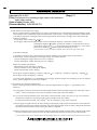
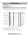
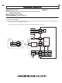
TECHNICAL BULLETIN
[Issue No.] FA-A-0047
[Title] Precautions for connecting a light curtain to the extension
safety relay module
[Date of Issue] October 2008
[Relevant Models] QS90SR2SP-EX
[Page] 1/7
Thank you for your continued support of Mitsubishi programmable controllers, MELSEC-QS series.
This bulletin provides further information of the precautions for connecting a light curtain*1, which has been informed in
"Clerical Errors in the Safety Relay Module User’s Manual" (BCN-P5719-A) attached to safety relay modules released in
and after July 2008.
Contrary to the contents of the above-mentioned notification, a light curtain can be connected to the extension safety relay
module (QS90SR2SP-EX) by correctly wiring according to Section 1 " Precautions for connecting a light curtain".
When connecting a light curtain to the extension safety relay module, observe the precautions given in Section 1 below.
*1: Output devices which have built-in power supply and do not require external power supply from the COM terminal, such as laser scanners, are
included.
Accordingly, related sections in the manual (SH-080746ENG-B (printed in June, 2008) or earlier) will be corrected. For
details, refer to Section 2 in this bulletin.
Corrections will take effect in the manual SH-080746ENG-C (printed in November, 2008).
1. Precautions for connecting a light curtain
When a light curtain is connected, safety shutdown from the QS90SR2SP-Q or QS90SR2SP-CC (hereinafter the "main
module") may have been disabled depending on the wiring configuration due to specifications of the product. To connect
a light curtain without disabling the shutdown function, wire the cables as the following connection diagram referring to
the precautions in this section.
Precautions given in this section will be described under "(5) Precautions for connecting a light curtain in Section 5.4.1
Precautions for safety devices and wiring" of the Safety Relay Module User's Manual.
Extension module
COM0
24V IN Control
output 1
To the main module
24G terminal
X0
COM1
Control
output 2
Safety light curtain
0V IN
X1
Figure 1.1 Extension module - light curtain external connection diagram
Safety shutdown from the main module turns off inputs by cutting off input power supplied to the COM terminal of the
extension module.
That is, if the wiring is configured so that power of the light curtain is supplied from the COM terminal of the extension
module, power supply of the light curtain turns off and outputs of the extension module stops consequently in the event of
the safety shutdown.
HEAD OFFICE : TOKYO BUILDING, 2-7-3 MARUNOUCHI, CHIYODA-KU, TOKYO 100-8310, JAPAN
NAGOYA WORKS : 1-14, YADA-MINAMI 5-CHOME, HIGASHI-KU, NAGOYA, JAPAN
TECHNICAL BULLETIN
[Issue No.] FA-A-0047
[Title] Precautions for connecting a light curtain to the extension
safety relay module
[Date of Issue] October 2008
[Relevant Models] QS90SR2SP-EX
[Page] 2/7
(1) Precautions for selecting power supply
Power supply input of a light curtain will be connected to the COM terminal of the extension module. Select a light
curtain compatible with the specifications for the COM terminal and X0/X1 terminals of the extension module.
Table 1.1 Specifications for selectable light curtains
Rated voltage
23 10 [V]
Total amount of current consumption of light curtain One light curtain is connected: 420[mA] or less
*1
Two light curtains are connected: 340[mA] or less
(receiver)
ON voltage
20.0[V] or more
OFF voltage/current
2.4[V] or less/2.0[mA] or less
*1: Current consumption = COM terminal output current (500[mA]) - ((X0 terminal input current (40[mA]) + X1 terminal input current
(40[mA])) Number of light curtains
The number of light curtains means the number of light curtains connected in one system.
One system means the system configured with one main module and one or more extension module(s).
Specifications for the COM terminal of the extension module
Rated voltage: 23 10 [V]
Output current: Maximum 500[mA]
Specifications for the X0 and X1 terminals of the extension module
ON voltage
: 20.0[V] or more
OFF voltage/current
: 2.4[V] or less/2.0[mA] or less
Input current
: Maximum 40[mA]
Input voltage
: Maximum 26.4[V]
HEAD OFFICE : TOKYO BUILDING, 2-7-3 MARUNOUCHI, CHIYODA-KU, TOKYO 100-8310, JAPAN
NAGOYA WORKS : 1-14, YADA-MINAMI 5-CHOME, HIGASHI-KU, NAGOYA, JAPAN
TECHNICAL BULLETIN
[Issue No.] FA-A-0047
[Title] Precautions for connecting a light curtain to the extension
safety relay module
[Date of Issue] October 2008
[Relevant Models] QS90SR2SP-EX
[Page] 3/7
(2) Precautions for selecting power supply
Power of a light curtain is supplied from power supply connected between +24V(SAFETY) and 24G(SAFETY) of the
main module via the COM terminal of the extension module. If the current or voltage supplied from the COM terminal
is insufficient, operation of the light curtain cannot be guaranteed. Select the power supply device which meets the
following conditions.
Power supply output voltage :24 10 [V]
Power supply output current :Main module current consumption (85[mA]) + (Extension module current
consumption (80[mA]) Number of extension modules) + (Total amount of current
*1
consumption of light curtain ) + ((X0 terminal input current (40[mA]) + X1 terminal
input current (40[mA])) Number of light curtains)[mA] or more
*1: Control output current is not included. If included, subtract the control output current amount.
[Calculation example]
A calculation example for the system with three extension modules and two light curtains is shown below.
In the example, current consumption of each light curtain is assumed as follows.
Current consumption of light curtain A (receiver): 120[mA]
Current consumption of light curtain B (receiver): 210[mA]
Safety relay module specifications
Main module current consumption: 85[mA]
Extension module current consumption: 80[mA]
X0/X1 terminal input current: 40[mA]
Power supply output current[mA] > 85[mA] + (80[mA]
Power supply output current[mA] > 815[mA]
3) + (120[mA] + 210[mA]) + ((40[mA] + 40[mA])
2)
As a result of the calculation, it is concluded that power supply which has output current 815[mA] or more is required
for the system configuration in the above example.
(3) Precautions for connecting a light curtain
When connecting a light curtain referring to the connection diagram shown in Figure 1.1, pay attention to the
following.
(a) Light curtains cannot be connected to the main module and the extension module respectively at the same. Only a
*1
switch such as an emergency stop can be connected as safety input of the main module.
(b) Up to three extension modules can be connected to one main module. In this case, however, up to two extension
modules are available for connecting a light curtain (one light curtain per module).
*1
For the third extension module, only a switch such as an emergency stop can be connected.
(c) Power supply of a light curtain is cut off by turning on (opening the contact of) the switch which is connected to the
input X0 and X1 of the main module. Check the time required for the light curtain to restart in the specification and
provide an interlock until the restart of the light curtain is completed.
(d) When connecting a switch to the X0 and X1 terminals of the main module, wire the cables so that the cable length
becomes within 10m for both between the X0 and COM terminals and between the X1 and COM terminals.
*1: Switch means a device whose condition between the COM terminal and X0 or X1 terminal is short-circuited when the switch is off (the
HEAD OFFICE : TOKYO BUILDING, 2-7-3 MARUNOUCHI, CHIYODA-KU, TOKYO 100-8310, JAPAN
NAGOYA WORKS : 1-14, YADA-MINAMI 5-CHOME, HIGASHI-KU, NAGOYA, JAPAN
TECHNICAL BULLETIN
[Issue No.] FA-A-0047
[Title] Precautions for connecting a light curtain to the extension
safety relay module
[Date of Issue] October 2008
[Relevant Models] QS90SR2SP-EX
[Page] 4/7
contact is closed) and that has no load to develop voltage drop in the closed circuit.
HEAD OFFICE : TOKYO BUILDING, 2-7-3 MARUNOUCHI, CHIYODA-KU, TOKYO 100-8310, JAPAN
NAGOYA WORKS : 1-14, YADA-MINAMI 5-CHOME, HIGASHI-KU, NAGOYA, JAPAN
TECHNICAL BULLETIN
[Issue No.] FA-A-0047
[Title] Precautions for connecting a light curtain to the extension
safety relay module
[Date of Issue] October 2008
[Relevant Models] QS90SR2SP-EX
[Page] 5/7
(4) Time chart
Figure 1.2 shows the operation timing of each device when safety shutdown is executed by the main unit in the system
where a light curtain is connected to the extension module.
Emergency
stop activated
Emergency
stop released
Emergency stop switch
(main module X0-X1)
Start-up switch (M mode)
(extension module XS0-XS1)
Light curtain
(extension module X0-X1)
Emergency stop
(activated status)
Emergency stop
(released status)
On
*1
*1
Off
Light curtain
(beams blocked status)
*2
*3
Safety output *4
(extension module Z00-Z01)
*5
Safety output *4
(extension module Z10-Z11)
*5
Safety output *4
(extension module Z20-Z21)
*5
Start-up switch
turned on
Light curtain
started
Beams blocked
Blocked status Start-up switch
terminated turned on again
Figure 1.2 Operation time chart when a light curtain is connected
*1: Confirm that the light curtain has started, and then turn on the start-up switch of the extension module.
*2: Light curtain start-up time differs depending on the type of the light curtain.
*3: Light curtain stop time differs depending on the type of the light curtain.
*4: As for safety output response time, time until output on is 50ms or less and time until output off is 20ms or less.
For details, refer to Section 3.4 "Extension Safety Relay Module Specifications" of the Safety Relay Module User's Manual.
*5: Safety outputs are turned off after the light curtain stops. Configure the system considering the time described at *3 and *4.
HEAD OFFICE : TOKYO BUILDING, 2-7-3 MARUNOUCHI, CHIYODA-KU, TOKYO 100-8310, JAPAN
NAGOYA WORKS : 1-14, YADA-MINAMI 5-CHOME, HIGASHI-KU, NAGOYA, JAPAN
TECHNICAL BULLETIN
[Issue No.] FA-A-0047
[Title] Precautions for connecting a light curtain to the extension
safety relay module
[Date of Issue] October 2008
[Relevant Models] QS90SR2SP-EX
[Page] 6/7
2. Manual correction details
(1) Section 3.4 Extension Safety Relay Module Specifications, Table 3.6 Performance specifications of QS90SR2SP-EX
(2/2) External connection diagram (page 3-11)
The connection device part within the external connection diagram will be corrected.
EA
EB
Monitor
circuit
EG
EP
Start-up
switch
Correct
Incorrect
COM
24VDC
(safety)
MC0
24V IN
X0
COM
OV IN
X1
Switches
XS0
MC1
Control
output 1
Control
output 2
XS1
COM
Internal
safety circuit
X0
COM
X1
K0
Safety light curtain
Z00
MC0
Z01
Z10
MC1
Z11
Safety relay
Z20
Z21
Motor
M
HEAD OFFICE : TOKYO BUILDING, 2-7-3 MARUNOUCHI, CHIYODA-KU, TOKYO 100-8310, JAPAN
NAGOYA WORKS : 1-14, YADA-MINAMI 5-CHOME, HIGASHI-KU, NAGOYA, JAPAN
K1
TECHNICAL BULLETIN
[Issue No.] FA-A-0047
[Title] Precautions for connecting a light curtain to the extension
safety relay module
[Date of Issue] October 2008
[Relevant Models] QS90SR2SP-EX
[Page] 7/7
(2) Section 5.4 Wiring, Table 5.4 Connectable safety devices (page 5-18)
Some notes for connecting a light curtain to the QS90SR2SP-EX will be added.
Contents of notes are the same as those given in Section 1 in this bulletin.
Incorrect
COM
X0
COM
X1
COM
X0
COM
X1
Table 5.4 Connectable safety devices
Terminal
Connectable device
Positive common
y No-voltage contact (mechanical switch)
Input X0
y Light curtain of Type4 (When using a light
Positive common
curtain, connect it to X0 and X1.)
Input X1
Positive common
Input X0
y No-voltage contact (mechanical switch)
Negative common
Input X1
COM
X0
COM
X1
COM
X0
COM
X1
Table 5.4 Connectable safety devices
Terminal
Connectable device
Positive common
y No-voltage contact (mechanical switch)
Input X0
y Light curtain of Type4*1 (When using a
Positive common
light curtain, connect it to X0 and X1.)*2
Input X1
Positive common
Input X0
y No-voltage contact (mechanical switch)
Negative common
Input X1
Module model
QS90SR2SP-Q
QS90SR2SP-CC
QS90SR2SP-EX
X0
QS90SR2SN-Q
QS90SR2SN-CC
QS90SR2SN-EX
X0
X1
X1
Correct
Module model
QS90SR2SP-Q
QS90SR2SP-CC
QS90SR2SP-EX
X0
QS90SR2SN-Q
QS90SR2SN-CC
QS90SR2SN-EX
X0
X1
X1
*1: Output devices which have built-in power supply and do not require external power supply from COM terminal, such as laser
scanners, are included.
*2: When connecting a light curtain to the QS90SR2SP-EX, refer to the precautions under (5) in Section 5.4.1.
HEAD OFFICE : TOKYO BUILDING, 2-7-3 MARUNOUCHI, CHIYODA-KU, TOKYO 100-8310, JAPAN
NAGOYA WORKS : 1-14, YADA-MINAMI 5-CHOME, HIGASHI-KU, NAGOYA, JAPAN
TECHNICAL BULLETIN
[Issue No.] FA-A-0047
[Title] Precautions for connecting a light curtain to the extension
safety relay module
[Date of Issue] October 2008
[Relevant Models] QS90SR2SP-EX
[Page] 8/7
(3) Section 5.4 Wiring, the text in (5) Connecting a light curtain (page 5-19)
The enclosed part of description will be corrected as follows.
Incorrect
(5)
Connecting a light curtain
When connecting a light curtain to the safety relay module, connect it to X0
and X1 sides as shown in Figure 5.9.
Connect light curtain power supply and safety part power supply by their
ground side or supply power from the same power supply.
Correct
(5)
Connecting a light curtain
When connecting a light curtain to the QS90SR2SP-Q or QS90SR2SP-CC,
connect it to X0 and X1 sides as shown in Figure 5.9.
Connect light curtain power supply and safety part power supply by their
ground side or supply power from the same power supply.
HEAD OFFICE : TOKYO BUILDING, 2-7-3 MARUNOUCHI, CHIYODA-KU, TOKYO 100-8310, JAPAN
NAGOYA WORKS : 1-14, YADA-MINAMI 5-CHOME, HIGASHI-KU, NAGOYA, JAPAN


![Model Q2AS (H) CPU (S1) User's Manual [1/2]](http://vs1.manualzilla.com/store/data/006867034_1-37d0fc894799b020d67c92be65e419bc-150x150.png)