1
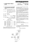
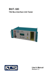
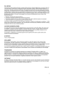
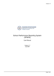
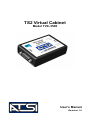
TS2 Virtual Cabinet
Model TVC-3500
User's Manual
Revision 1.0
Table of Contents
Table of Contents
1. Explanation of Symbols and Terms...................................................................2
2. Introduction to TS2 Virtual Cabinet..................................................................3
3. Installing TS2 Virtual Cabinet...........................................................................4
3.1. Software installation.................................................................................4
3.2. TVC-3500 USB Driver Installation..........................................................4
3.3. Connecting TVC-3500..............................................................................5
4. TS2 Virtual Cabinet Interface............................................................................6
4.1. Main Control Window..............................................................................6
4.2. MMU Setup..............................................................................................8
5. Running the TS2 Virtual Cabinet....................................................................10
5.1. Controller Unit Configuration................................................................10
6. Service and Calibration...................................................................................11
7. Limited Warranty.............................................................................................12
TVC-3500 User's Manual, Rev. 1.0
1
1. Explanation of Symbols and Terms
1. Explanation of Symbols and Terms
The following is a list of symbols and important terms that are used throughout
this manual. It is assumed that the reader is familiar with the operation of a
NEMA TS2 Type Traffic Control System.
Caution. Risk of danger. This symbol indicates important
information that must be read and understood before
attempting to install or use the TS2 Virtual Cabinet
2
Frame
A predefined format for the messages that are exchanged
using the SDLC protocol. The NEMA TS2 Standard
defines command frames (sent by the controller) and
responses frames (sent by BIUs and conflict monitors).
NEMA
National Electrical Manufacturers Association.
PC
Personal computer
SDLC
Synchronous Data Link Communication Protocol. Serial
communication protocol by which the controller, BIUs,
and conflict monitor exchange information in a TS2 type
traffic control system.
TS 2
Traffic Control Systems Standard published by NEMA
(see NEMA).
BIU
Bus Interface Unit. A device that receives SDLC
commands from the Controller Unit and provides digital
inputs and outputs to interface with external devices such
as detectors, load switches, etc.
TVC-3500 User's Manual, Rev. 1.0
2. Introduction to TS2 Virtual Cabinet
2. Introduction to TS2 Virtual Cabinet
The TS2 Vritual Cabinet (TVC-3500) provides the full emulation of a NEMA
TS 2 standard cabinet. It connects to an SDLC port (Port 1) of a NEMA TS 2
standard Controller Unit (controller). TVC-3500 receives SDLC frames from the
controller, processes those frames and sends responses back to the controller. It
also runs a full simulation of TF BIUs 1-4 (Terminals and Facilities), DR BIUs
1-4 (Detector Rack BIU), and an MMU. To monitor this virtual cabinet, TVC3500 is connected to a PC running the user interface software.
Through the interface software (TS2 Virtual Cabinet Interface), the user can
change inputs and monitor outputs of the TF BIUs, and simulate detector calls.
This allows the user to monitor the controller's "reaction" to various inputs such
as emergency vehicle preempt call, pedestrian call on a particular phase or an
actuation of any detector call.
The software will also automatically enable inputs/outputs for those BIUs that
are programmed in the controller and show which BIUs should be present in the
cabinet. This provides a visual presentation of how the controller is setup and
what inputs/outputs are available for the given controller configuration.
TVC-3500 User's Manual, Rev. 1.0
3
3. Installing TS2 Virtual Cabinet
3. Installing TS2 Virtual Cabinet
3.1. Software installation
Installation of the software is a simple process. However it may require an
administrative access to the computer.
The TVC-3500 comes with a software CD which can be used to install the
software. If the CD is not available, the software can be downloaded from the
Internet. To download the software visit our website: www.atsi-tester.com.
To install the software from a CD insert it into the CD drive of the PC. A start-up
screen should open automatically. In the start-up screen click "Install TS2
Virtual Cabinet Interface Software" button, then follow the instructions in the
software installation wizard.
To install the software that was downloaded from our website double-click the
downloaded executable file to run the installation. Follow the instructions in the
software installation wizard.
Note: Do not forget to install the USB driver for TVC-3500.
3.2. TVC-3500 USB Driver Installation
To communicate with TVC-3500 an ATSI Tester USB driver needs to be
installed. The same driver is used with several ATSI products and is included on
the software installation CD. A copy of the driver installation package can also
be downloaded from the Internet. To download the driver go to our website:
www.atsi-tester.com. The driver installation package is also copied to the
computer during software installation.
To install the USB device driver from a CD insert it into the CD drive of the
computer. A start-up screen should open automatically. In the start-up screen
click "Install ATSI Tester USB Driver" button, then follow the instructions in the
device driver installation wizard.
To install the USB device driver package that was downloaded from our website
double-click the downloaded executable file to run the installation. Follow the
instructions in the device driver installation wizard.
To install the USB device driver from the package copied during software
installation open My Computer and navigate to the directory where the TS2
Cabinet Simulation Interface software was installed. In the directory, open the
4
TVC-3500 User's Manual, Rev. 1.0
3. Installing TS2 Virtual Cabinet
folder caller "driver" and run dpinst.exe. Follow the instructions in the device
driver installation wizard.
3.3. Connecting TVC-3500
TVC-3500 is connected to the controller using the already attached cable. It is
connected to the computer using a USB cable. The power to TVC-3500 is
supplied through the USB cable thus eliminating the need to have an external
wall adapter.
TVC-3500 is a high power USB device and according to the USB specifications
may draw up to 500mA from the USB host. Make sure the USB host is capable
of powering a high power USB device or a powered USB hub is used.
Note: The SDLC cable used with TVC-3500 is a cross cable. Transmit and
receive lines in the cable are switched. To avoid the possibility of using the
wrong cable to not disconnect the SDLC cable from the TVC-3500.
TVC-3500 User's Manual, Rev. 1.0
5
4. TS2 Virtual Cabinet Interface
4. TS2 Virtual Cabinet Interface
4.1. Main Control Window
The Virtual Cabinet Interface window is show below.
Tool Bar
MMU Panel
Signals
BIUs Present
TF BIU Outputs
TF BIU Inputs
DR BIU Loop Call Inputs
Detailed description of each section:
Tool Bar has the following controls available:
Connect button. Click this button to connect the interface
software to the virtual cabinet TVC-3500.
6
TVC-3500 User's Manual, Rev. 1.0
4. TS2 Virtual Cabinet Interface
Disconnect button. Click this button to disconnects the
interface from the virtual cabinet TVC-3500.
MMU Setup button. Click this button to open the MMU
Programming Card Configuration window.
About button. Click this button to view the contact information,
the software version, and the firmware version.
Help button. Click this button to open the TS2 Virtual Cabinet
Help window.
Signals section displays the current state of the signals. If TFBIU #1 is
disabled in the controller, signals 1-8 will not be shown. If TFBIU #2 is not
enabled in the Controller Unit, signals 9-16 will be hidden. 9-16 or 1-16 will
be displayed.
BIUs Present section shown which BIUs are enabled in the controller.
Hovering the mouse cursor over each BIU icon will highlight the
corresponding TFBIU Outputs (section ), Inputs (section ), or DRBIU Loop
Call Inputs (section ) connected to that BIU.
TF BIU Outputs show the current state of the outputs.
MMU Panel shows indications of the MMU. The Reset () button allows the
user to reset the virtual MMU and clear a fault state (conflict).
In TF BIU Inputs section, inputs to the BIUs can be activated or deactivated.
To activate an input check the corresponding checkbox. To deactivate the
input uncheck the checkbox. If a checkbox is disabled, the input is not
available because the corresponding BIU is not enabled in the Controller
Unit.
Loop calls can be activated or deactivated in DR BIU Loop Call Inputs
section. To activate a loop call, check the corresponding checkbox. To
deactivate a loop call uncheck the corresponding checkbox. If the checkbox
is disabled, the corresponding DR BIU is not enabled in the Controller Unit.
TVC-3500 User's Manual, Rev. 1.0
7
4. TS2 Virtual Cabinet Interface
4.2. MMU Setup
The MMU Programming Card settings can only be changed when the interface
is not connected to TVC-3500. If connected, click Disconnect button on the
toolbar.
To open the MMU setup window click
following window.
button. This will open the
The available MMU Programming Card configurations are:
Compatibility Programming
A check mark in the compatibility checkbox indicated that the corresponding
pair of channels is compatible (permissive).
8
TVC-3500 User's Manual, Rev. 1.0
4. TS2 Virtual Cabinet Interface
Minimum Yellow Change Channel Disable Programming
Minimum Yellow Change monitoring is not implemented in the virtual
MMU 1. However, the Minimum Yellow Change configuration will be
reflected in the Type 129 MMU Inputs/Status response frame.
Minimum Flash Programming
Since there is no definite instance when the virtual cabinet is powered up, the
Minimum Flash Time is not implemented in the virtual MMU 1. However,
the minimum flash programming will be properly reflected in the Type 129
MMU Inputs/Status response frame.
Voltage Monitoring Latch Programming
Since TVC-3500 is connected to the Controller Unit through an SDLC bus,
the Virtual MMU cannot monitor the CVM on the CU. It also does not have a
24V power supply. Thus, +24V Latch and CVM/Fault Monitor Latch are
only reflected in the Type 129 MMU Inputs/Status response frame.
To apply changes and close the MMU Setup dialog window, click OK button.
To discard any changes and close the MMU Setup dialog window, click Cancel
button.
MMU Programming Card configuration can be saved to be quickly loaded in the
future. To save a predefined configuration type the name of the configuration in
the Predefined Configuration box and click Save button. Click OK to confirm
the operation in the opened message box.
Note: Only alpha-numeric (a-z, A-Z,0-9), _ (underscore), - (minus), and
space characters are allowed in the configuration names. Any other typed
character will be replaced with an underscore ( _ ).
To load a predefined configuration, click on of the Predefined Configurations
drop down box and select the name of the configuration to be loaded. Click OK
button in the opened message box to confirm the operation.
To delete a user defined configuration, select it from the drop down box. Click
Cancel when prompted to confirm loading the new configuration. This would
put the name on the configuration in the text box without loading new settings.
Click Delete button to delete the configuration.
1 Subject to change. New features may be added in the future firmware updates/releases.
TVC-3500 User's Manual, Rev. 1.0
9
5. Running the TS2 Virtual Cabinet
5. Running the TS2 Virtual Cabinet
Make sure the Interface Software and the TVC-3500 USB driver are installed
and TVC-3500 is connected to the Port 1 of the Controller Unit and also
connected to a USB port of the computer. The POWER indicator on the TVC3500 should be ON.
Start the TS2 Virtual Cabinet Interface software.
When the software opens, configure the Virtual MMU Programming card by
clicking MMU Setup button and selecting the proper configuration. Refer to the
MMU Setup section on page 8 for detail description of the MMU settings. Click
OK button to apply the MMU settings and close the MMU Setup window.
After the MMU is configured, click Connect button to connect the Interface
software to TVC-3500. After connecting, the Connect and MMU Setup button
should be disabled and Disconnect button should be enabled.
Apply power to the Controller Unit. Now, the virtual cabinet should be running.
Inputs to the Controller can be changed by checking and unchecking the
checkboxes in the TF BIU Inputs and DR BIU Loop Call Inputs sections. If a
change in the MMU Programming Card is needed, disconnect from TVC-3500
by clicking Disconnect button, change the MMU configuration, and click
Connect button again.
5.1. Controller Unit Configuration
The Controller Unit should have at least one of TFBIU#1 or TFBIU#2 enabled.
This allows the virtual BIUs to generate correct signals to the Virtual MMU thus
providing correct information for the MMU Inputs Status Response frame Type
129.
It is also important to have the Permissives (Compatible Channnels)
configuration in the Virtual MMU Programming Card to match the
configuration in the Controller Unit. If the Controller unit detects a mismatch, it
would automatically put the intersection into the flashing state.
10
TVC-3500 User's Manual, Rev. 1.0
6. Service and Calibration
6. Service and Calibration
The TVC-3500 has no user serviceable parts. Under no circumstances should
the user attempt to open the enclosure.
If the TVC-3500 appears to be malfunctioning, contact ATSI to make
arrangements for repair. See the Limited Warranty section of this manual for
details.
The TVC-3500 is shipped from the factory completely calibrated and tested. No
further calibration should be required.
TVC-3500 User's Manual, Rev. 1.0
11
7. Limited Warranty
7. Limited Warranty
The TVC-3500, TS2 Virtual Cabinet (Product), distributed by Athens
Technical Specialists, Inc. (ATSI), is warranted to the original purchaser
(Purchaser) to be free of defects in materials and workmanship for a period of
one year from the purchase date stated on the invoice. Within this period, in the
event of a defect, malfunction, or other failure of the product while in the
custody of the Purchaser, ATSI will remedy the defect or cause of failure without
charge to the Purchaser. The Purchaser's sole remedy is restoration of product
operation. ATSI accepts no liability for incidental or related expenses. Under
no circumstances will ATSI's liability exceed the purchase price for items
claimed to be defective.
This Limited Warranty does not extend to any Product that has been damaged or
rendered defective as a result of accident, misuse, abuse, modification of the
product, or service by anyone other than ATSI.
EXCEPT AS EXPRESSLY SET FORTH IN THIS WARRANTY, ATSI MAKES
NO OTHER WARRANTIES, EXPRESS OR IMPLIED, INCLUDING ANY
IMPLIED WARRANTIES OF MERCHANTABILITY AND FITNESS FOR A
PARTICUALR PURPOSE. ATSI EXPRESSLY DISCLAIMS ALL
WARRANTIES NOT STATED IN THIS LIMITED WARRANTY. ANY
IMPLIED WARRANTIES THAT MAY BE IMPOSED BY LAW ARE
LIMITED TO THE TERMS OF THIS EXPRESS LIMITED WARRANTY.
Warranty Repair
To return the Product for repairs :
Request a Return Merchandise Form by phone, fax, or email from the ATSI
Service Department or complete the form at www.atsi-tester.com. Return the
Product along with the completed form with prepaid postage to :
ATSI
8157 US Hwy 50
Athens, OH 45701
12
TVC-3500 User's Manual, Rev. 1.0
TS2 Virtual Cabinet
Model TVC-3500
User's Manual
Revision 1.0