1
GAS-VOLUME CONVERSION DEVICE
miniELCOR
Device Description
Operation Manual
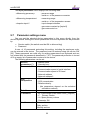
Technical Description
Mounting instructions
Device settings
Single-channel conversion device of gas volume at measurement conditions to
volume at base conditions. Approved for installation in potentially explosive
atmospheres.
January 2010
Rev. 6g
Safety Measures
This measurement device can be operated only by an operator trained in
compliance with the technical terms, safety regulations, and standards. It is
necessary to consider any other legal and safety regulations stipulated for special
applications. Similar measures also apply for special applications. Similar measures
also apply for using the accessories. The operator training must be in compliance
with Decree no. 50.1978 Coll.
The information in this manual does not have the burden of a legal obligation from the
manufacturer’s side. The manufacturer reserves the right to implement changes. Any
changes in the manual or in the product itself can be performed at any time without any
previous alert, with the goal of improving the device or fixing any typographical or technical
mistakes.
TABLE OF CONTENTS 1 Introduction ............................................................................................. 1 1.1 Basic device description ........................................................................................ 1 1.2 Function principle .................................................................................................. 2 1.3 Device dimensions ................................................................................................. 7 2 Device technical description ..................................................................... 7 2.1 2.2 2.3 2.4 Device architecture ............................................................................................... 7 Device power supply ............................................................................................. 8 Security marks ..................................................................................................... 11 Product label ....................................................................................................... 13 3 Safety instructions ................................................................................... 14 3.1 3.2 3.3 3.4 3.5 General ............................................................................................................... 14 Use in potentially explosive atmospheres ........................................................... 14 Risks of usage ...................................................................................................... 14 Special conditions of use ..................................................................................... 15 Using device variants for different groups of gas ................................................. 15 4 Metrology characteristics ........................................................................ 16 4.1 4.2 4.3 4.4 Measuring temperature ...................................................................................... 16 Measuring pressure ............................................................................................. 16 Compressibility calculation .................................................................................. 17 Volume measuring and calculation ...................................................................... 18 5 Connecting inputs and outputs ................................................................ 21 5.1 Inputs .................................................................................................................. 21 5.2 Outputs ............................................................................................................... 25 5.3 Adding of another pressure or temperature transducer ...................................... 26 6 Communication with device .................................................................... 29 6.1 RS‐232 and RS‐485 interfaces .............................................................................. 29 6.2 Optical interface IEC‐1107 ................................................................................... 31 7 Description of function ............................................................................ 33 7.1 7.2 7.3 7.4 7.5 Measurand marking ............................................................................................ 33 Instantaneous values ........................................................................................... 33 Archives .............................................................................................................. 34 Device parameterization ..................................................................................... 37 Other device functions ........................................................................................ 38 7.6 Securing the device against a change of metrology parameters .......................... 38 8 Putting in operation ................................................................................ 44 9 Device operation ..................................................................................... 45 9.1 9.2 9.3 9.4 9.5 9.6 9.7 9.8 9.9 Keypad ................................................................................................................ 45 Menu system ....................................................................................................... 46 Main menu .......................................................................................................... 49 Instantaneous values menu ................................................................................. 50 Stored values menu ............................................................................................. 50 Device parameters menu ..................................................................................... 51 Parameter settings menu .................................................................................... 52 System data menu ............................................................................................... 53 Diagnostics menu ................................................................................................ 54 10 Mounting instructions ............................................................................. 57 10.1 Mechanical mounting of the device ..................................................................... 57 10.2 Cable connection, grounding ............................................................................... 61 11 Accessories .............................................................................................. 63 11.1 Assembly accessories .......................................................................................... 63 11.2 Intrinsically safe supply sources for external power supply ................................. 63 11.3 Separation and communication modules ............................................................ 63 11.4 GPRS communicators .......................................................................................... 63 11.5 Other accessories ................................................................................................ 63 12 Technical parameters .............................................................................. 64 13 Inexplosiveness parameters .................................................................... 70 14 Device setting .......................................................................................... 72 14.1 Standard device control after installation ............................................................ 72 14.2 Device connection with PC .................................................................................. 73 14.3 Setting of communication between device and PC .............................................. 73 14.4 Password in the device ........................................................................................ 84 15 Configuration examples ........................................................................... 86 15.1 Device parameters displaying .............................................................................. 86 15.2 Gas meter constant setting .................................................................................. 86 15.3 Pulse outputs setting ........................................................................................... 89 15.4 Analogue output setting ...................................................................................... 94 15.5 Setpoint setting – limit values of measured quantity ........................................... 97 15.6 Setting of external power supply failure ............................................................. 100 15.7 Setting of communication through MODBUS protocol ....................................... 101 16 Pressure and temperature sensor/transducer replacement .................. 105 16.1 Pressure and temperature sensor/transducer replacement procedure in miniELCOR device ............................................................................................... 105 16.2 Software settings of device for proper communication with new temperature sensor ................................................................................................................. 105 16.3 Software settings of device for proper communication with new pressure transducer .......................................................................................................... 108 17 Software settings of the device for proper communication with external digital temperature (EDT‐34) or pressure transducer (EDT‐23) .............. 109 17.1 Adding of digital transducer into device’s parameters ........................................ 109 17.2 Adding of quantity measured by digital transducer into device’s archives .......... 110 18 Final verification of the device after replacement of sensor/transducer or adding of digital transducer ................................................................... 111 19 What to do if something does not work ................................................ 116 20 Literature .............................................................................................. 119 21 Relevant Literature ................................................................................ 119 22 Software ................................................................................................ 120 23 Used trade marks .................................................................................. 120 24 List of figures ......................................................................................... 121 25 List of Tables ......................................................................................... 123 miniELCOR
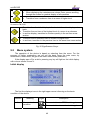
Used symbols and definitions
Symbol
AGA8-G1
AGA8-G2
AGA8-92DC
AGA NX-19 mod
...
...
...
...
ASC
BTS
CL 1
CRC
CTR
DATCOM-Kx
...
…
...
...
...
...
DLMS
DC
dE
dV
dVb
dVc
dVm
E
Es
EDTxx
...
...
…
…
…
…
…
…
…
…
EMC
EMI
firmware, FW
GOST NX-19
...
...
...
...
Hs
IS
JBZ-0x
Modbus
M900
SGERG-88
...
SNAM
SW
C
K
kp
N
p
pb
...
...
...
...
...
...
...
...
...
...
...
...
...
Meaning
Calculation method of gas compressibility factor
Calculation method of gas compressibility factor
Calculation method of gas compressibility factor
Calculation method of gas compressibility factor
Accredited Service Center
Base Transceiver Station
Module for realization of product output 4-20mA
Checksum – used for data protection
Communication protocol
Some of the products of series DATCOM-K (DATCOMK1,
DATCOM-K2,
DATCOM-K3,
DATCOM-K3/A,
DATCOM-K4, DATCOM-K4/A)
Communication protocol
Direct Current voltage
addition (difference) of energy
addition (difference) of primary volume Vm or Vc
addition (difference) of base volume
addition (difference) of corrected primary volume
addition (difference) of primary volume
Energy
Estimated value of energy
Digital pressure or temperature transducer EDT 23 or
EDT 34
Electromagnetic compatibility and resistance
Electromagnetic radiation
Software equipment loaded in the device
Method of gas compressibility calculation ( related with
AGA NX-19 mod) according to VNIMS directive (valid at
temperature range -23°C to +60°C)
Combustion heat
intrinsic safety, intrinsically safe
Some of the JBZ-01, JBZ-02, JBZ-02/A products
Communication protocol designed by Modicon [15]
Specific communication protocol
Calculation method of gas compressibility factor, more
details in Chyba! Nenalezen zdroj odkazů.
Communication protocol
Software for PC
Conversion factor
Ratio of compressibility factors (Z/Zb)
Gas meter constant (number of impulses per 1 m3)
Number of input impulses from gas meter
Absolute pressure at measurement conditions
Absolute pressure at base conditions
1
Unit
MJ
m3
m3
m3
m3
MJ
MJ
GOST
NX-19
MJ/m3
imp/m3
imp
kPa
kPa
miniELCOR
Qm
Qb
T
t
Tb
V
Vm
Vc
Vb
Vbs
Vs
Vd
Vbd
Vf
Vbf
Z
Zb
... Flowrate at measurement conditions ( further primary
flowrate)
... Flowrate at base conditions
... Absolute temperature at measurement conditions (T = t +
273.15)
... Gas temperature
... Absolute temperature at base conditions
... Volume Vm or Vc
... Volume at measurement conditions (further primary
volume)
... Corrected volume at measurement conditions ( volume
corrected based on correction curve of gasmeter)
... Volume at base conditions (hereinafter also the
standardized volume)
... Error volume at base conditions (hereinafter also the
error standardized volume)
... Error volume at measurement conditions (hereinafter
also the error operational volume)
... Difference of primary volume
... Difference of base volume
... Tariff pulse counter of primary volume
... Tariff pulse counter of base volume
... Compression gas factor at measurement conditions
... Compression gas factor at base conditions
Notice :
This handbook issue describes device functions with firmware FW 4.xx which is
compatible with previous firmware version 2.xx. All different features will be
mentioned respectively.
Chapters describing new device features of FW ver. 4.xx are marked with (*).
2
m3/h
m3/h
K
°C
K
m3
m3
m3
m3
m3
m3
m3
miniELCOR
1
1.1
Introduction
Basic device description
The Gas-volume conversion device miniELCOR (hereinafter only “the device”)
is a measuring instrument designed for the conversion of the gas volume measure at
measurement conditions to volume at base conditions.
The information on the gas volume passing through is measured using the
impulse outputs of the gas meter. The gas temperature and pressure are measured
by integrated converters. The device calculates the ratio of compressibility factors of
gas using standard methods or a constant value is used.
The device has been constructed and approved pursuant to the EN 12405-1
standard as a conversion device type 1 (compact system) and can be supplied as a
T, PT, or PTZ conversion device.
From safety point of view device is constructed according to EN 60079-11 like
intrinsic safe.
It is manufactured and supplied in compliance with the following European
Parliament directives:
1994/9/EC
Equipment and protective systems for use in potentially explosive
atmospheres
2004/108/EC Electromagnetic compatibility
2004/22/EC Directive on measuring instruments
Device is put onto market and into usage according to above mentioned
standards and is marked with CE mark.
The device is built in a casing with sturdy plastic with IP66 protection. It is
equipped with a graphic display and a 6-button keypad. Furthermore, it has impulse
inputs for the connection of a gas meter with LF or HF impulse output and binary
inputs. Device with FW version 4.xx and higher is suitable for connection via encoder
NAMUR or SCR. If applied encoder SCR the only miniELCOR SCR1 variant is
allowed. The binary inputs can work as check inputs to check the connection with a
gas meter or can have a different function, e.g. monitoring the conditions of safety
snap locks, doors, etc. The device has 4 available outputs. These can be configured
as impulse or binary outputs, or as data outputs for the CL-1 module. When using
this module, an analog current output can be realized.
The device is powered by a lithium battery. The life cycle of the battery is 6
years in the defined work mode. In the case of a battery power supply, one can also
use the impulse outputs. An external power supply source can be used in
applications with higher demands.
The device has a data archive of the measured values with an adjustable
structure and storing period. The binary archive stores changes on the binary inputs
and the occurrence of the monitored events (limits, etc.) Error conditions are stored
in an status archive. It is possible to program the storing of important quantities and
calculations and storage of some statistical values in the daily and monthly archive.
The archive has settings for service and metrology; in case of changes of settings,
the acts influencing the device parameters are recorded. The other logs are available
as well , see more in 7.3.
1
miniELCOR
For communication with its superior system, the device has a serial interface
RS-232 and RS-485. Various communication protocols installed in the device allow
easier connection to the SCADA systems. The device cooperates with common
phone, radio, GSM, and GPRS modems, and in case of an alarm condition, it can
initiate the connection.
The device can be enhanced by one non-metrology converter for measuring
pressure or temperature. This enhancement can be performed without breaking the
official mark on an already installed device.
-
1) Basic configuration of the device offers following inputs and outputs:
analog input (pressure P - metrologic channel)
analog input (temperature T - metrologic channel)
4x digital input DI1 to DI4 (binary, pulse); input DI1 can be used for connecting
encoder NAMUR
4x digial output DO1 to DO4 (binary, pulse, analog)
communication channel RS485/RS232 for communication with suprordinate
systém
input of external power supply
option: connection one digital pressure or temperature transmiter EDTxx (as
nometrologic) to internal bus by help expansion board KP 065 08. This
enhancement can be accomplished by end user on already installed device
without breaching of metrological seal.
2) Device variant with SCR encoder ensures following inputs and
outputs:
-
The same like at basic device variant ( see ad 1) however without possibility
of connection of digital transducer EDTxx
1x input for SCR encoder connection by means of extention board KP 065 09
The device can be configured using the supplied SW [22] for PCs. This SW also
allows the readout, display and archive of both the immediate measured values as
well as the contents of the internal device archives.
1.2
Function principle
1.2.1 Conversion using equation of state
The device obtains data on the gas flowing through via impulses (N) from an lf
or hf sensor located in the gas meter. The volume at the measuring conditions (V) is
calculated from the number of impulses (N) and gas meter constant (kp).
The device obtains other data on the gas flowing through from the temperature
and pressure converters – gas temperature (t) and absolute pressure at measuring
conditions (p). This data is used to calculate the conversion factor (C) which is
influenced also by these other factors: Absolute temperature at base conditions (Tb),
absolute pressure at base conditions (pb) and compressible factor of the gas at base
conditions (Zb).
2
miniELCOR
Volume at measuring conditions (operational volume):
N
V=
kp
Ratio of compressibility factor:
Z
K=
Zb
Conversion factor:
p
Tb
1
C=
*
*
pb
(t + 273.15)
K
Volume at base conditions (standardized volume):
Vb = V * C
Gas compressibility factor expresses the deviation of properties of natural gas
from the properties of an ideal gas. By setting the parameters, it is possible to choose
a specific method for calculation of the compressibility factor pursuant to the standard
(AGA NX-19 mod, AGA8-G1, AGA8-G2, SGERG-88 or AGA8-92DC). A constant
compressibility value can be used for other gases besides natural gas. If the
pressure or temperature value gets out of the limits of validity of the chosen standard
for calculation of compressibility, the device calculates using a default compressibility
value.
The device calculates the gas flow from the impulse frequency on the input in
real time using mathematical filtration from the input signal.
Operational flow:
Q = ∆V / ∆t [m3/h]
Where: ∆V ............................
increment of operational volume
∆t .............................
time between the impulses with an accuracy
of one hundredth of a second
The value of the immediate flow displayed on the converter display is updated
every 10 seconds.
Standardized flow:
Qb = C * ∆V / ∆t [m3/h]
1.2.2 Error values of volumes at measuring conditions and
volumes at base conditions
For calculation during error conditions (i.e. in case of a converter error,
deviation of the quantity value from the working range, or device error), the device
has counters of the error volume at measuring conditions (Vs) and error volume at
base conditions (Vbs). These counters are interconnected with the pertinent counters
of volume at normal conditions.
A detailed description of device behavior during normal and error conditions is
in Article 4.4.
3
miniELCOR
1.2.3 Volume correction at measurement conditions
Device enables to compensate gasmeter error according to predefined
correction curve from gasmeter test certificate. This function and parameters Vc can
be activated only by manufacturer or by Acreditive service to ensure that used
gasmeter correction curve in dependance on flowrate Qm is valid within working
conditions.
Error of measurement is corrected by usage of function f(Qm). For corrected
volume is:
Vc = Vm x f(Qm)
where
... Corrected volume at measurement conditions
Vc
Vm
... Primary volume
Qm ... Primary flowrate
Linear interpolation method is used for getting values between calibration
points. File with correction values is to be inserted into device with help of service
programme 22. Information about insertion of correction curve into device is logged
in setup archive.
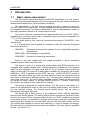
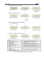
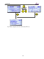
The principle of volume calculation are seen on Fig. 1
Condition for usage of volume correction.
1. Correction is used only in case that gasmeter transmits at least 10 pulses
per second resulting in usage only HF sensors.
2. Under Qmin correction is not applied and over Qmax value of correction
coefficient given for Qmax will be used.
Conversion of volume on energy (*)
Device enables to calculate consumpted quantity of gas directly in energy form.
This conversion uses value of combustion heat Hs. Calculation is made with
adding of differences dVb ( and dVbs) multiplied by actual value of combustion heat
Hs.
dE=Hs x dVb, dEs=Hs x dVbs
Two other counters ( energy counter E and estimated energy counter Es) are
dedicated for measurement in configurable energy units: MJ, kWh, Btu.
Note :
No conversion of absolute counter value (E or Es) is accomplished after
change of units. Following increases are added already respecting new units.
Principle diagram of energy calculation is drawn at Fig. 1
4
miniELCOR
Combustion heat Hs
To get correct conversion it is necessary to enter correct value of combustion
heat and relative conditions. Then device will make new conversion of relative
temperature for defined relative conditions and final value will be used for energy
calculation. In case of AGA8-92DC method combustion heat is not entered but
calculated directly from gas composition according to EN ISO 6976. For the other
methods value Hs (MJ/m3) must be entered manually and always under those
relative conditions:
combustion temperature/ temperature of gas = 25°C / 0 °C
5
miniELCOR
Fig. 1 Volume and energy calculations - Scheme
6
miniELCOR
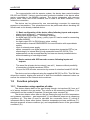
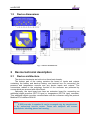
1.3
Device dimensions
Fig. 2 Device dimensions
2
Device technical description
2.1
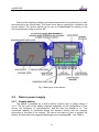
Device architecture
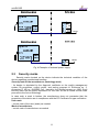
The device’s electronics are laid out on three basic boards.
The bottom part of the casing contains the board of inputs and outputs
containing the battery and back-up battery and terminal box for connecting the
pressure and temperature sensors and any device inputs and outputs. The
connections related to the metrology function of the converter are protected by
covers which are secured with official mark.
Optionally, the input board can have an extension board for connecting an
additional digital pressure (EDT 23 type) or temperature (EDT 34 type) converter.
This additional digital converter communicates with the converter using the protocol
Modbus RTU interface RS-485.
Note:
If SCR encoder is required it can be arranged only by manufacturer
or by authorised service center. Those two subjects will ensure
appropriate labelling placed on housing.
7
miniELCOR
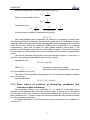
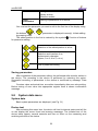
The lid of the housing contains a processor board which is protected by a cover
and secured by an official mark. The board cover has an opening for access to the
service switch. The service switch can be use to enable/disable the setting of the
device parameters using a service SW.
Fig. 3 Main parts of the device
2.2
Device power supply
2.2.1 Supply battery
The device is powered by a built-in battery (lithium) with a voltage rating of
3.6 V. The life cycle of the battery depends especially on the configuration of the
device, the frequency of communication, and the time the display is on. The
consumed capacity is calculated during the device’s activity and the capacity
decrement is recorded in its memory. The device will issue an alert to replace the
battery 90 days before the expected discharge (error messages E9 – see Table 8.
8
miniELCOR
Defined mode with life cycle of the supply battery of more than 5 years:
• Archiving period of the data archive 1 hr
• Communication with device 2 min/day
• Showing on the display 2 min/day
• Period of input impulses ≤10 Hz
• Measuring period 15 s
• Surrounding temperature 25 °C
• expansion board KP 065 09 ( SCR encoder ) is not used
If the device is operated with higher consumption than in the defined mode, it
is necessary to count on a more frequent replacement of the battery or use a network
power source.
2.2.2 Replacement of supply battery
Replacement of battery is allowed also at hazardous zone but only with
recommended type of battery.
. It is suitable to disconnect the discharged battery as soon as possible. While
the battery is being replaced, the device does not measure pressure or temperature,
but counts the incoming lf impulses (but does not convert the number of pulses, this
will be performed only when the supply battery is connected again) and insures that
the real time clock is running. The data stored in the device archives and parameter
settings will remain preserved.
Due to correct calculation of remaining battery capacity after replacement it is
mandatory to reset this information with service SW tool [22].
Discharged batteries belongs at hazardous waste category. According to
OEEZ (2002/96/ES) directives and and other internal directives battery must not be
disposed together with household waste. Withdrawing duty is applied over
discharged battery.
2.2.3 Back-up battery
The battery ensures the back-up of important functions in case of discharge or
replacement of the supply battery. The back-up battery can be replaced in an
accredited service center after the official and security mark is broken (replacement
can not be performed in a potentially explosive atmosphere). It is necessary to use
the same type of battery. Only recommended type of battery may be used.
9
miniELCOR
Defined mode for life cycle of back-up battery of 10 years
• Storing, temperature 25 °C
• Backed-up inputs (DI1 – DI4) not connected or connected contacts
disconnected
• Does not depend on the presence of the supply battery
Defined mode for life cycle of back-up battery of 4 years
• Backed-up inputs (DI1 – DI4) short-circuited
• Without powering battery
Self-discharging of batteries
The back-up and supply batteries are lithium. Their capacity drops due to selfdischarging. The recommended time frame for their replacement is 10 years, even if
the battery was never connected.
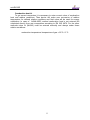
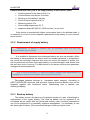
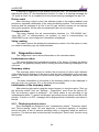
2.2.4 External power supply
Usage of external power supply is necessary in case of appliance of:
- NAMUR HF pulse input
- Binary output
- NAMUR encoder.
External power supply is recommended in case of increased current consumption
regimes like:
- frequent communicationi (more than once a day),
- frequent LCD displaying
- SCR encoder usage.
An approved intrinsically-safe source must be used for the external power
supply. In case a NAMUR type sensor is not connected to the device, one can use
the built-in sources of the communication modules DATCOM-Kx or sources JBZ-01,
JBZ-02.
If the NAMUR sensor is connected to the device, one must always use an
external power source JBZ-01 or JBZ-02.
10
miniELCOR
Fig. 4 Examples of external power supply
2.3
Security marks
Security marks located on the device indicate the technical condition of the
device regarding unauthorized handling.
Security mark of the manufacturer (metrology mark)
- its design is stipulated by the Approval certificate on the quality management
system for production, output control, and testing pursuant to Enclosure no. 2,
procedure D, ND no. 464/2005 Coll., issued by the Notified person no. 1383. Such
security mark has the same importance for the user as the so called Official mark
pursuant to the Act on Metrology.
In case such a mark is broken, the manufacturer does not guarantee that the
properties of the device are in compliance with the EC Certificate on type verification.
User mark
- control mark of the user (seals) as needed
Mark of manufacturer
- control mark of manufacturer as needed
11
miniELCOR
Fig. 5 Security marks (device without SCR encoder)
Fig. 6 Security marks of miniELCOR SCR
12
miniELCOR
2.4
Product label
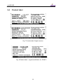
Fig. 7 Product label English version
Fig. 8 Product label – original certification for ZONE 1
13
miniELCOR
3
Safety instructions
3.1
General
The device has been approved pursuant to the guideline 94/9/CE and an EC
certificate on type verification (ATEX) has been issued for it’s use in potentially
explosive atmospheres. Respecting this guideline is included in the CE compliance
notation.
3.2
Use in potentially explosive atmospheres
Based on the EC certificate in type verification 08 ATEX 0324X, the device can
be operated in potentially explosive atmospheres with a classification of ZONE1
(potentially explosive atmosphere during normal operation) and ZONE2.
Device is fully in compliance with EN 60079-26 ed.2 (viz [4]) and ATEX
approval 08 ATEX 0324X was extended by Supplement n.3 for hazardous ZONE 0.
Indication of the device regarding safety against explosion:
II 1G Ex ia IIC T4/T3
II 2G Ex ib IIB T4/T3
….
….
miniELCOR
miniELCOR SCR
Environment temperature for temperature class T4:
Environment temperature for temperature class T3:
Zone 0
Zone 1
-25 °C to +40 °C
-25 °C to +70 °C
The entire device has been constructed and approved as intrinsically
safe. That means that only approved devices (intrinsically safe devices,
consecutive devices) or so called simple devices complying with the
EN 60079-11 standard and complying with the intrinsically safe parameters
listed in the EC Certificate on verification type [16] can be connected to the
device connectors.
The pertinent safety standards must be met when connecting.
When connecting a device, it is necessary to consider the electrical
characteristics of the connecting cables and abide by the requirements of the
pertinent safety standards. Furthermore, it is necessary to abide by the Special
conditions of use provided these certificates contain them. The parameters of nonexplosiveness of the device are listed in 13.
3.3 Risks of usage
Device cabinet is produced from polycarbonate material. Foil keypad of
polystyrene is placed on top cover. In some extreme cases electrostatic charge
accumulated on surface of cabinet could cause explosion. To avoid explosion it is
strictly recommended to keep the following rules:
14
miniELCOR
•
•
3.4
At hazardous zones device must not be installed at places where outer
conditions could create an electrostatic charge.
Device may be cleaned by humid wiper.
Special conditions of use
1. The device must not be installed and located in an environment with a
potential danger of electrostatic charge of the device casing (e.g. by
flowing air, etc.) Only a damp cloth must be used if the device is being
cleaned, to prevent from creation of electrostatic charge.
2. Only the following types of supply batteries are admissible in the device:
Saft LS33600, Saft LS14250.
3.5 Using device variants for different groups of gas
Individual variants of device can be used only with certain groups of gas
according to this table.
Group of gas
IIC
IIB
IIA
miniELCOR
yes
yes
yes
miniELCOR SCR
no
yes
yes
Device variant
15
miniELCOR
4
4.1
Metrology characteristics
Measuring temperature
This device uses the PT1000 temperature sensor to measure temperature. The
temperature sensor’s connection is two-wired. The influence of the length and the
characteristics of the cable used are considered during calibration and therefore do
not influence the accuracy of the temperature measuring.
The temperature measuring range is -25 °C to +60 °C. The measuring period is
common for both the measuring of temperature and pressure and it can be custom
set at a range from 1 s to 30 s. The temperature measuring units can be adjusted.
Replacement of the temperature sensor is protected by the security mark of the
manufacturer (metrology mark) and can be performed solely at an Accredited Service
center (ASC).
During device configuration, the user must enter the constant parameter
Default temperature value. This value will be used for the calculation of
compressibility instead of the measured temperature value in the following cases:
- The value of the measured temperature deviated from the measuring
range
- An error occurred when measuring the temperature
4.2
Measuring pressure
Pressure measuring is ensured by an analog converter. The converter contains
a piezoresistive silicon sensor with a resistant stainless steel membrane. The device
electronics ensures the correction of non-linearity and the temperature dependency
of the pressure sensor based on the calibration data saved in the device memory.
The measuring range of the pressure converter must be requested by the customer
when ordering the device. The available pressure ranges are listed in chapter 12.
The measuring period is common for both the measuring of temperature and
pressure, and can be custom set at a range from 1 to 30 s. The pressure measuring
units can be set.
Replacement of the pressure converter is protected by a security mark of the
manufacturer (metrology mark) and can be performed solely at an Accredited Service
center (ASC).
During device configuration, the user must enter the constant parameter
Default pressure value. This value will be used for the calculation of compressibility
instead of the measured pressure value in the following cases:
- The value of the measured pressure deviated from the measuring range
- The device is manufactured without the pressure converter (so called TZ
or T corrector)
- An error occurred when measuring the pressure
16
miniELCOR
4.3
Compressibility calculation
4.3.1 PTZ, TZ conversion
The compressibility factor is calculated from the composition of the gas listed in
the parameters, using one of the following methods implemented in the device: AGA
NX-19-mod, SGERG-88, AGA8-G1, AGA8-G2 or AGA8-92DC.
Calculation of the compressible factor is performed in each measuring period. In
the SGERG-88 and AGA8-G1 methods the value of the heat of combustion is
entered for the combustion temperature 25°C / gas temperature 0°C. The service SW
contains a built-in calculator for the conversion of the heat of combustion at different
temperatures.
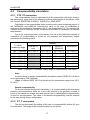
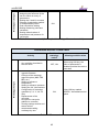
Due to the required accuracy of the device, the use of the individual methods of
calculation of compressibility is limited by the pressure and temperature ranges
pursuant to the following table:
Method
Pressure
measuring range
AGA NX-19
mod
SGERG-88
AGA8-G1
AGA8-G2
AGA8-92DC
80 ÷ 520 kPa
200 ÷ 1000 kPa
400 ÷ 2000 kPa
700 ÷ 3500 kPa
1400 ÷ 7000 kPa
-25 ÷ +60 °C
N/A
N/A
N/A
N/A
-25 ÷ +60 °C
-25 ÷ +60 °C
-25 ÷ +60 °C
-10 ÷ +60 °C
-10 ÷ +60 °C
-25 ÷ +60 °C
-25 ÷ +60 °C
-25 ÷ +60 °C
-10 ÷ +60 °C
-10 ÷ +60 °C
-25 ÷ +60 °C
-25 ÷ +60 °C
-25 ÷ +60 °C
-25 ÷ +60 °C
-25 ÷ +60 °C
80 ÷ 1000 kPa
400 ÷ 7000 kPa
N/A
N/A
-25 ÷ +60 °C
-10 ÷ +60 °C
-25 ÷ +60 °C
-10 ÷ +60 °C
-25 ÷ +60 °C
-25 ÷ +60 °C
Table 1 Limitation of standard validity range of compressibility calculation
Note:
At device there is applied compressibily calculation method GOST NX-19 which
is not approved by ČMI certificate.
Usage of method GOST NX-19 is limited only for temperature range from -23°C
to +60°C.
Default compressibility
For the set method during each calculation, it is checked whether the measured
pressure and temperature value are in the valid interval of the pertinent method. If
some of the values are outside the valid interval, the so called default compressibility
is used for the conversion. The value of the default compressibility must be entered
by the user during device configuration.
4.3.2 PT, T conversion
The device also allows the setting of the ratio of compressibility factors (K) as a
fixed constant. The range of the entered constant is not limited.
17
miniELCOR
4.4
Volume measuring and calculation
For measuremet and volume calculation there are used following counters for
each channel.:
Vm - Primary volume counter
Vc
- Corrected volume counter (volume corrected based on gasmeter
correction curve)
V
- Volume Vm or Vc
Vs
- Counter of the operational volume at error conditions (error
operational volume)
Vb
- Counter of volume at base conditions (standardized volume)
Vbs - Counter of standardized volume at error conditions
4.4.1 Operation at error conditions
In case of the occurrence of error conditions, the device, at the same time as
counting the impulses in the counter of the volume at measuring conditions (V), starts
to count the impulses in the counter of the error volume at measuring conditions (Vs).
The values of the volumes at base condition (Vb) will stop being counted in the
counter of the volume at base conditions (Vb), and will be counted from the default
values of pressure or temperature and will be stored in the counter of the error
volume at base conditions (Vbs). During this condition, the values are not stored in the
counter of volume at base conditions (Vb).
18
miniELCOR
Fig. 9 Storing impulses in counters
If a default compressibility is used during the calculation for the reason of
deviation of accuracy for the set calculation standard outside the allowed value (see
article 4.3.1), whereas p or t are not outside the measuring range, the converted
volume is stored in the error counter.
If corrected volume Vc is used primary volume counter can be linked to Vm or
Vc. at error conditions..
4.4.2 Recognition of gas flow direction change of gas meter (*)
Flow direction detection is enabled for gasmeter equipped with two phases
shifted LF sensors or encoders. Both ways are approved for custody transfer at EC
type approval amendement. Corrector evaluates gas flowrate respecting direction
changes ( Pict. 9) under following terms:
- If primary volume additions are positive in such case volume processing
is made by standard procedure ( for example increasing of Vm and Vb, or
Vms and Vbs).
- If gas flow direction is changed device will fix the value of primary volume
counter at the moment of turn. When gas flows back only primary
volume Vm (or Vms) is updated. The other counters are frozen.
19
miniELCOR
-
After returning back to correct direction counting will get blocked out into
apropriate counters (Vb, Vbs) only after reaching level of primary volume
where reversed flow was started up. Primary volume counter is equivalent
to gasmeter counter all the time.
Fig. 10 Processing of volumes during reversed flow
20
miniELCOR
5
5.1
Connecting inputs and outputs
Inputs
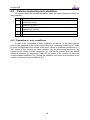
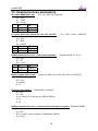
A total of 4 digital inputs marked as DI1 to DI4 can be connected to the device.
The inputs are brought out at the terminal board inside the device. The digital inputs
can be adjusted using the service SW as a binary or as a LF impulse. The DI1 and
DI2 can also be set as HF impulse or binary type NAMUR. In devices with FW ver.
4.xx input DI1 may be setup also for connection with NAMUR encoder
Input
DI1
DI2
DI3
DI4
Binary
contact
√
√
√
√
Binary
LF
HF
NAMUR
impulse
impulse
√
√
√
√
√
√
√
√
Table 2 Digital inputs setting options
encoder
NAMUR
√
-
5.1.1 LF impulse inputs
Serves to read impulses from a gas meter. The flow measuring function can be
chosen for these inputs. The back-up battery ensures preservation of counters’
conditions and reading the impulses of the LF inputs also in case of the discharge or
replacement of the supply battery. After connection of the supply battery, the
impulses read during the outage of voltage of the supply battery are added to the
error counters. The LF impulse input is, on the DI1 and DI2 inputs, connected
between the terminals LF+ and LF- (see Fig. 12).
Changing measuring units, setting the gas meter constant
The measuring units of the impulse inputs can be changed using the service
SW [22]. The conversion constants of the gas meter and S/N of gas meter can be set
using the service SW as well as directly from the device keyboard. When setting the
value of the gas meter constant, only decimal folds or fractions in range from 0.01 to
100 are expected.
Number of places of counters of lf impulse inputs
In the case of lf impulse inputs, the counter works with 9 valid digits, the gas
meter constant influences the size of the maximum number from 9 999 999.99 (for
constant = 0.01) to 99 999 999 900 (for constant = 100).
5.1.2 HF impulse inputs (NAMUR)
The inputs DI1 and DI2 can be configured for processing HF impulses from the
sensors of type NAMUR. Due to the fact that these sensors require a supply voltage
higher than the voltage of the supply battery of the device, the converter must have
an external supply voltage higher than 7 Vdc (e.g. from JBZ-02) for the registration
and processing of HF impulses.
The flow measuring function can be chosen for these inputs. The back-up
battery ensures the preservation of counters’ conditions in case of an outage of the
external supply even in the case of discharge or replacement of the supply battery,
21
miniELCOR
but it does not ensure the counting of the impulses. The terminals for the HF NAMUR
inputs are marked HF+ and HF- (see Fig. 12).
Changing measuring units, setting the gas meter constant
The impulse inputs measuring units and the gas meter constant can be
adjusted using the service SW. The gas meter constant and S/N of gasmeter can be
also set from the device keyboard.
Number of places of counters of the hf impulse inputs
In the case of hf impulse inputs, the counter works with 9 digit places.
5.1.3 Connection with gasmeter via encoder (*)
Gasmeter can be connected with corrector via encoder. Digital value of
gasmeter counter is transferred into EVC. Two types of encoders are supported like
NAMUR and SCR.
The usage of encoders is approved for metrological reasons by EC- type
certificate TCM 143/06-4664, Adition 1.
Encoder NAMUR
No special HW is required for NAMUR encoder usage. The only condition for
NAMUR encoder data processing is usage of IS external power supply JBZ-02 ( or
JBZ-01).
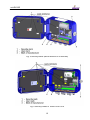
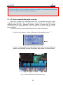
Encoder SCR
To process data from SCR encoder miniELCOR SCR type must be used
complemented with KP 065 09 board. This board must be complemented directly
only by manufacturer. Additional assembly at customer side is not allowed. Encoder
board is connected with input board via IS RS485 Bus ( there is used connector
dedicated for digital transducer connection ( see Pict.3 and Pict.4). This type of
encoder can be also used for only battery powered EVC but it is too much energy
consuming. Enduser should take care about it during parameterisation.
5.1.3.1 Encoder NAMUR input
Connection between EVC and encoder is made with shielded two wires cable.
NAMUR encoder may be connected only via digital input DI1. Terminals for encoder
are the same like for HF pulse input marked HF+ and HF- ( correct signal polarity is
important.). NAMUR encoder connection must be setup in EVC parameters with SW
Telves 22.
5.1.3.2 Encoder SCR input
Connection between EVC and encoder is made with shielded two wires cable
via terminals marked A and B board SCR (KP065 09). No matters on conductor
polarity. Encoder data are transferred into EVC at default measurement period. The
shorter measurement period has bad impact on battery life.
22
miniELCOR
If SCR encoder is used at battery regime at standard 30s measurement period
battery life will be decreased down to 2 years.
5.1.3.3 Device specification with encoder
Data from encoder are transferred into EVC via shielded two wires cable.
Together with absolute value of gasmeter counter there are transferred other
additional data like S/N , gasmeter constant, number of figures nine for counter
overturning). These additional data are read out with service SW 22 usable at device
parametrisation.
In case of error at communication between EVC and encoder then:
-
At actual value primary volume is displayed with asterisk symbol “ * “ .
-
If error of communication is longer than 10 min there is volume difference
added into estimated volumes immediately after restart of communication.
Fig. 11 Encoder SCR board (without cover)
23
miniELCOR
Manual setup of primary volume counter Vm is not allowed at encoder input..
Installation and replacement of gasmeter
Actual counter of gasmeter is transferred into EVC after connection of encoder
and EVC possibly causing big difference at primary volume Vm. To prevent against
affection of base volume Vb (Vbs) it is necessary to keep following instruction:
1. In service SW 22 display device parameters, select subject „Encoder SCR“
and push button „Encoder exchange“. During encoder exchange will be
stopped processing of primary volume from gasmeter. (Further follow
instructions shown on PC display).
2. Connect physically encoder to EVC.
3. After connection of encoder finish installation/exchange with OK button.
During installation/exchange ( meant from point 1) no differences are added to
appropriate counters which are marked on display with exclamation mark. If point 3 is
not finished by one hour exchange procedure will be closed automatically at service
SW.
5.1.4 Binary inputs
These inputs monitor the input signals with the option of an evaluation of the
condition “connected” (i.e. log. 0) or “disconnected” (log. 1). The device allows the
evaluation of the binary inputs from the no-potential outputs (reed contact or open
collector – these signals are on DI1 and DI2 inputs connected to terminals LF+, LF-)
or from sensors of the type NAMUR (DI1 and DI2 inputs, terminals HF+, HF-) The
NAMUR sensors require an external supply voltage of the converter higher than 7 V
(e.g. from JBZ-02).
By setting the parameter, the user can choose the display of the instantaneous
values on the display, storing the changes of these inputs in the archive; display the
headline for condition log. 0 and log. 1, and active signal level.
24
miniELCOR
Fig. 12 Inputs and outputs terminals
5.2
Outputs
The device has 4 digital outputs DO1 to DO4 which can be configured as
binary, impulse, or data. A data output serves for the realization of an analog output
4-20 mA using the CL-1 module which is connected to this output.
The outputs can be controlled by the device using the calculation equations
entered by the user in the device parameters (for example, it is possible to generate
outputs according to the volume of the gas flown through, indication of alarm
condition, exceeding the set limits of pressure or temperature, etc).
The device structure allows the generation of outputs even when the device is
powered solely by the battery with no effect on the battery life cycle. The outputs are
“open collector” type and are not galvanic separated. All four outputs have a joint
GND conductor.
The outputs are intrinsically safe, thus when connecting standard devices, the
devices must be connected via a safety barrier (e.g. DATCOM-K3, see Fig. 13).
Impulse outputs
The impulse outputs have adjustable width and impulse periods in folds of 0.1 s.
The debt of impulse outputs can reach max. 65535 pulses. An output constant can
also be realized in the setting equation of the output quantity.
Binary outputs
Output terminals are according to the output quantity in the connected or
disconnected condition. In the resting state, the output terminals are disconnected
(condition log.1).
Data output
The digital output configured as a data output serves for communication with
the CL-1 module. An analog output 4-20 mA can be realized using this module.
25
miniELCOR
Using the calculation equations, the value of the output can be parameterized as
proportional to pressure, flow, daily consumption, etc. The CL-1 module must be
connected to the converter via a safety barrier (DATCOM-K3).
Fig. 13 Example of an impulse (binary) output and current output scheme
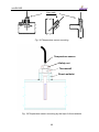
5.3
Adding of another pressure or temperature
transducer
Beyond standardly mounted pressure and temperature transmitters which are
metrologically approved according to EC-type certificate it is possible to add aditional
pressure or temperature transducer.
This extention is not possible for devices already equipped with expanding
SCR encoder board.
Quantity measured by this additional pressure or temperature transducer is not
metrological value. It means that it is not included in to the metrological part of the
device. Measured values is possible to store in to the archives and also show actual
values on the display.
As additional transducer can be used either digital pressure transducer EDT 23
or temperature digital transducer EDT 34. Digital transducer is using for
communication internal intrinsically safe serial bus RS-485 and MODBUS RTU
26
miniELCOR
protocol. On account of intrisic safety must be connected transducer intrinsically safe
- “ia” type. Type of the transducer is necessary to specify in time of order.
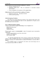
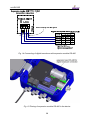
For connection of additional digital transducer (EDT 23, EDT 34) must be
volume corrector equipped with expansion RS-485 module (KP 065 08) (see Fig. 15).
Expansion module RS-485 and additional digital transducer there are not part of
standard accesories and it is neccessary to order it separately. Module RS-485 can
be ordered additionally and by this way expand already installed device.
Digital transducer is connected to the RS-485 clamps of expansion module.
Only one digital transducer can be connected to the expansion module.
Connecting/disconnecting of transducer and also of RS-485 module can be done
only when power supply is disconnected.
Procedure of connecting expansion module RS-485 and digital transducer
1. Disconnect volume corrector from external power supply ( if present)
2. Open the device and remove battery
3. Unscrew plastic cover of input/output board in place of plugging
expansion module RS-485 (factory seal will be breached)
4. Insert expansion module in to the X4 board of inputs. After inserting of
the module there it is neccessary to check if some connector pin is not
out of the contact tube. All pins must be inserted in to the connector
properly
5. Apply cover delivered with the expansion module and screw the
expansion board with input/output board
6. Connect digital transducer. Cable of the transducer pull through the cable
bushing. Shielding of the cable attach with body of the bushing. Electrical
scheme of connecting expansion module RS-485 is shown on Fig. 14.
7. Check digital transducer connection
8. Connect device back to the power. It is inserting of battery and external
power supply connection (if present)
After installation of digital transducer it is important to add it in to the parameters
by the help of service software (see paragrapph 17).
27
miniELCOR
Fig. 14 Connecting of digital transducer with expansion module RS-485
Fig. 15 Placing of expansion module RS-485 in the device
28
miniELCOR
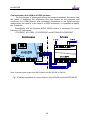
6
Communication with device
For communication with other devices, the device is equipped with one
communication channel which brings it to a total of three communication interfaces.
Either the communication interface RS-232 or the RS-485 can be used for
connection with a superior system. The optical interface is designed for operative
readout or device settings.
In the current firmware version, the device is equipped with several
communication protocols. The device is prepared for extension by other protocols as
required by the customer. The standardly implemented protocols are ELGAS ver.2
and MODBUS RTU. Preset communication protocol is the same for all
communication interfaces. It is possible to change communication speed for metalic
interface and for optical interface independently.
The ELGAS ver.2 protocol is the native protocol of the device. A complete set of
functions realized in the device is available. The service SW [22] solely uses this
protocol – in case it is necessary to switch to other link level, the ELGAS ver.2
protocol is only wrapped in one other link level (a so called “a tunnel”). The ELGAS
ver.2 protocol is used as the only one for loading firmware (protected by the
metrology mark).
The communication circuits are galvanic separated from other device circuits.
Because of the galvanic separation, the communication circuits must be powered
from outside, from a connected device (CTS signal in case of the RS-232 interface
and U1+ in case of the RS-485 interface).
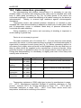
6.1
RS-232 and RS-485 interfaces
Both interfaces are brought out to the internal terminal board and, although they
are simultaneously functioning, only one of these interfaces can be used (connected)
for communication at a time. Because both of the interfaces are intrinsically safe, it is
necessary during installation to separate the device in a potentially explosive
environment from the connected common device (computer, modem, etc.) by a
consecutive device (DATCOM-Sx, DATCOM-Kx, MTL 5051 etc.), or use a device
with a intrinsically safe design.
The communication speed of the interface (the speed is joint for both interfaces)
and the communication protocol can be set in the device parameters.
Communication via modem controlled by AT commands
Basic setting features of a modem for the correct cooperation with the device:
• Sending answer (ATQ0)
• Long format of the sent answers (ATV1)
• Echo disabled (ATE0)
• Automatic pickup (ATS0=1)
• Set firmly serial port communication speed of the modem (e.g. for speed
38400 Bd is command AT+IPR=38400)
• Ensure presence of power feeding on clamp DSR of the modem (by
command AT&S0). Clamp DSR is interconnected with CTS clamp of
device.
More detailed information must be found in the manual of the used modem.
29
miniELCOR
Communication with GSM and GPRS modems
For the purpose of diagnostics during the modem installation, the device has
the option of displaying the information from the modem on the presence and
connection to a GSM network, and furthermore information on the signal strength
measured by the modem. In the case of a GPRS connection, it is possible to display
the IP address.
Compatibility with the Siemens MC35, MC39 modem is necessary for correct
function in AT commands:
AT+CREG?, AT+CSQ?, AT+CGDCONT and AT^SGAUTH+CGDCONT.
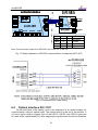
Note: Communication output from DATCOM-K3 can be RS-485 or RS-232
Fig. 16 Safety separation of communication using RS-485 module DATCOM-K3
30
miniELCOR
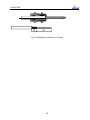
MTL 5051 setting
Switches
OFF
ON
meaning
SW1a
X
‐‐‐
other modes
SW1b
X
‐‐‐
5V output
SW2a
RS232 RS422 output interface
SW2b
RS422 RS232 output interface
Note: Communication output from MTL5051 can be RS-232 or RS-422
Fig. 17 Safety separation of RS-232 communication via separator MTL 5051
Fig. 18 Communication cable wiring
6.2
Optical interface IEC-1107
On the front face of the casing, next to the keyboard, is an optical window for
communication using an optical head. The optical head is to be put to the window. It
is fixed in place using a magnet. One of the HIE-01, HIE-03, and HIE-04 types can
be used as the optical head [13]. After applying the optical head, the device transfers
31
miniELCOR
from the economy mode to the mode in which it is able to accept data. It remains in
this mode for 180 s from the last communication (timeout) or until the user takes the
optical head of the communication interface.
Warning:
After applying the head, the communication channel from the RS-232/RS-485
device to the optical interface. That means that the communication via the RS-232 or
RS-485 is discontinued until the moment the optical head is removed, or until the
mentioned timeout from the last communication expires.
The communication speed of the optical interface can be set in the device
parameters independently of the speed of the RS-232/RS-485 interface. The setting
of the communication protocol is combined for all three interfaces.
32
miniELCOR
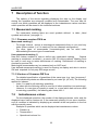
7
Description of function
The options of the device regarding displaying the data on the display and
storing the quantities are extremely variable and customizable. The user has full
control over which quantities will be displayed in the instantaneous values and also
which quantities will be stored in the individual archives.
7.1 Measurand marking
For measurand marking there are used symbols defined
symbols and notions“ (see page 1).
in table „Used
7.1.1 Firmware version FW 4.xx
Measurand marking (*)
- For single channel device at metrological measurands there is not used any
index (Index number 1 or 2 is used only for two channels configuration)
- For other types of measurands (nonmetrological) can be used index
differentiating the same type of measurands.
User measurand marking (*)
New SW feature enables to user to define own measurand marking.
Original
marking is considered as default ( at service SW 22 is blue marked). Marking must
be used in such way to retain definiteness of marking. Definiteness of marking is
checked by service SW.
Metrological measurands may be renamed only on ASC level.
User defined measurand marking is used for showing on display and also in service
SW and exported for 3rd party SW usage as well.
7.1.2 Version of firmware FW 2.xx
For detailed specification of quantities of the same type (e.g. type “pressure p”
etc.), the individual symbols are differentiated by an index (p1, p2, etc.) The following
applies for indexes:
- Index 1 is used for all metrology quantities.
- An index with the following value is used for all other quantities (non-metrology).
However, if a new type of quantity is used (i.e. a type which has not been used
in metrology quantities), the indexing also starts from 1.
7.2
Instantaneous values
For the displayed quantities, the number of the displayed places, units, and the
displayed name can be custom set. If the measured quantity is in an error condition,
such a condition is indicated by displaying an asterisk at the last position in the line
with the quantity name.
Example of quantities which can be displayed as instantaneous values:
• Pressure p
• Temperature t
• Operational volume Vm
33
miniELCOR
•
•
•
•
•
•
•
•
•
•
•
7.3
Error operational volume Vms
Standardized volume Vb
Error standardized volume Vbs
Flow Qm
Standardized flow Qb
Conversion factor C
Compressibility ratio K
Device error
External power supply presence
Battery capacity
Internal temperature
Archives
The values are arranged in the archives in time sections, a time data of the
section, and values of the individual quantities selected for archiving form a part of
each time section.
The measured and calculated quantity values can be stored in the following
archives:
• Monthly archive
• Daily archive
• Data archive
• Binary archive
• Limits archive
Besides the listed data archives, the device also contains the following archives:
• Event archive
• Billing archive
• Settings archive
• Gas composition archive
First stored in the available device memory are the archives with a fixed number
of records (monthly, daily, binary, and limits) and the data archive is placed in the
remaining memory (its length depends on the size of the remaining memory).
Data
Daily Monthly Limits Binary
archive archive archive archive archive
Analog quantities
Input analog – mean value
yes
yes
yes
Internal analog – mean value
yes
yes
yes
Output analog – mean value
yes
yes
yes
Minimum/maximum
yes
yes
yes
yes
yes
Impulse quantities, flow measuring
Operational volume – absolute condition
34
yes
2)
miniELCOR
Standardized volume – absolute condition
yes
yes
yes
Error operational volume – absolute condition
yes
yes
yes
Error standardized volume – absolute condition
yes
yes
yes
Max. daily consumption – operational volume
Yes
1)
Max. daily consumption – standardized volume
Yes
1)
Max. hourly consumption – operational volume
Yes
1)
Yes
1)
Max. hourly consumption – standardized volume
Yes
1)
Yes
1)
Internal counter – absolute condition
yes
yes
yes
Output impulses – impulse debt condition
yes
yes
yes
Operational flow – mean value
yes
yes
yes
Standardized flow – mean value
yes
yes
yes
Minimum/maximum flow
yes
yes
Conversion factor – mean value
yes
yes
yes
Ratio of compressibility factors – mean value
yes
yes
yes
Minimum/maximum of conversion, of ratio of
compressibility factors
yes
yes
yes
2)
yes
2)
Conversion, ratio of compressibility factors
Binary quantities
Binary input - condition
yes
yes
Binary output - condition
yes
yes
Set points - condition
yes
yes
yes
yes
yes
yes
Device errors
converters
Internal binary
and
communication
with
Other quantities
Counter/timer – absolute condition
yes
Input code
yes
Notes:
1) Hour or day is stored along with the value (or combination, whichever suitable).
2) Date and time or achieving the minimum/maximum is stored along with the value.
Table 3 Options of archiving the individual quantities
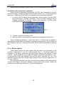
7.3.1 Monthly archive
Archive capacity: 25 records
The values are saved in the archive once a month at the set “gas company“
hour (usually 6:00 am). The time data of the record is stored in the archive along with
the values. If the archive is full, new data will start to overwrite the oldest ones. There
is an option to store the statistical values of gas consumptions and analog quantities
(see. Table 3).
35
miniELCOR
The record with date 01.06 thus means statistical values of quantities in interval
1.05. 6:00 to 1.06. 6:00.
7.3.2 Daily archive
Archive capacity: 400 records
Has similar features to the monthly archive (for the list of options see Table 3);
even here can be stored statistical values of gas consumptions and analog
quantities. The values are stored in the archive once a day in the set “gas company”
hour (usually 6 p.m.).
The record with date 13.06 thus means statistical values of quantities in interval
12.06. 6:00 to 13.06. 6:00.
7.3.3 Data archive
Archive capacity: Is variable pursuant to the configuration of the stored
quantities. The capacity is operatively displayed during the
configuration of the archive in the service SW.
Archiving period: Adjustable within 1 s to 1 hr
The quantities in this archive are saved in the set time period, and the period
interval can be set by the user. The preset value is 1 hr. In the case of state values,
the archive stores the occurrence of the active state in the pertinent archiving period.
For binary inputs, the active state can be set according to the actual state of the
parameterizations; log.1 is the active state for set points and errors.
7.3.4 Binary archive
Archive capacity: 2000 records
The archive stores the binary input states, state bites calculated and stored in
the system, and errors of the individual devices. The values are stored in the archive
only provided the state of one of the stored binaries changes. A time date with
resolutions in seconds is a part of the record.
7.3.5 Limits archive
Archive capacity: 1 record for each monitored quantity
Reaching an extreme (minimum or maximum) is saved for the archived
quantities. The archive saves the value and a time mark. When initiating this archive,
the actual measured values of the specific quantities are set in the registers of
minimums and maximums.
7.3.6 Event archive
Archive capacity: 500 records
The archive stores the date and time of the event change, state word (64 bits)
describing the statuses of all the monitored events in the device and state of the
counter of operational volume V1 and counters of the standardized volume Vb1. The
list of monitored events in the device is in the Table 8 and Table 9.
This archive, unlike the previous archives, will not rotate after it has been filled.
The archive content can not be displayed directly on the display, but it can be
displayed using the service SW on a PC.
36
miniELCOR
7.3.7 Settings archive
Archive capacity: An average of 500 records (depends on length/type of
records)
The settings archive stores changes of parameters, especially if they have
effect on metrological features of the device. The archive also stores the identification
of the employee who performed the change. The record contains a time mark,
employee identification, description of his/her activity, and eventually the new and old
values of the parameters which were changed.
This archive, similarly as the event archive and unlike the other archives, does
not rewind, i.e. after filling the archive up, one can not add to it and other changes of
parameters are disabled. This archive can not be displayed on the display, and the
content can only be displayed using a PC.
7.3.8 Billing archive (*)
Archive capacity: 15 records
Device contains billing archive. This archive serves as data recorder with billing
period setup at device parameters. There are two possible ways how to write into
this archive – one time writing according to preset time or periodically at intervals
1,2,3,4,6 or 12 months. At this time new record of all actual counters like primary
volume and base volume is created including both total counter and single tariffs.
Billing period is configurable and crossing time as well..
7.3.9 Gas composition archive (*)
Archive capacity: 150 records
When gas composition or compressibility calculation method are changed new
record is stored into this archive. The record contains time and date stamp, previous
used compressibility method and value of gas composition items. If this archive is full
the oldest data records are overwritten. Notice: in old FW version changes of gas
composition are recorded in setup archive.
7.4
Device parameterization
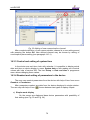
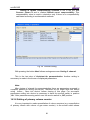
7.4.1 Parameterization using service SW
The device provides a wide range of options regarding its settings. Due to the
wide range, the parameterization is performed in a full scope using the supplied
service SW [22] designed for PCs. Besides the device settings, this SW also allows
the read out, display, archiving, and printing of the instantaneous values as well as
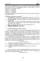
the archive contents. Description of the parameterization using the SW is in [19].
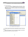
7.4.2 Parameterization from the device keypad
The device allows the setting of some of the selected parameters directly from
the device keypad, i.e. without using a computer. These parameters are:
• Service parameters: station name, gas hour
• Communication settings: Name of station, communication protocol, transfer
speed, network address, network address 2
37
miniELCOR
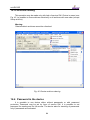
•
•
•
Gas composition (individual components of the gas pursuant to the set
calculation method)
Date and time in the device
volume parameters like setup of gasmeter constant, Vm, Vms, Vb, Vbs, S/N
of gasmeter
Settings description is in the Art. 9.7.
7.5 Other device functions
7.5.1 Summer/winter time (DST) (*)
In device summer/winter time exchange function is implemented which can be
activated ( or deactivated) with service SW. If activated then device makes changes
automatically based on selected region (Europe or USA). Paralelly it is necessary to
setup deviation from GMT. In device archives is marked whether record was made in
summer ( resp. in winter) time.
7.5.2 Time synchronisation (* - only Italian version)
Device is equipped with time synchronisation function enabling time correction
by authorised administrator within +/- 60s range without record into event log. If
deviation is bigger than 60s upto 2 hours then time correction is allowed but record
into event log is created. If deviation is bigger than 2 hours then time correction is
denied and alarm signal is generated.
7.5.3 Tariff counters (*)
In device there are available four tariff counters enablig volume calculation
based on default time schedule. Two independent schedules (Tariff schedule 1 and
Tariff schedule 2), are changed mutually in active ( resp. nonactive) mode. Single
tariffs are assigned to time slots in single days and paralelly days can be defined like
working days, Saturdays or Sundays ( or holiday)
Each schedule has own ID number and activation time of each schedule is
adjustable separately.
7.5.4 Remote download (*)
Remote download according to specification WELMEC 7.2 enables upgrade of
FW remotely . For such purpose FW is equipped with unique digital signature
overcoming security system at device.
7.6
Securing the device against a change of metrology
parameters
The device is equipped with a metrology and service switch and uses a
password system of protection against an unauthorized manipulation especially with
the data which affect the metrology features of the device. Changes in device
settings and other acts are stored in the settings archive. These means allow the
securing of the device in compliance and even above the requirements of the
EN 12405-1 standard.
38
miniELCOR
7.6.1 Switch protection
There are two switches located inside the device – the metrology switch and the
service switch.
7.6.1.1 Metrology switch
- protects the metrology settings of the device. It is located on the inside of the
casing cover (see Fig. 3) and protected by a label which is secured by a
manufacturer’s security mark (official metrology mark) – see Fig. 5, Fig. 6.
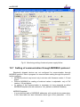
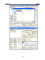
7.6.1.2 Service switch
- is located next to the metrology switch (See Fig. 3). It is doubled, and when
switching, it is necessary to switch both parts of the switch. Opening of the device
and thus the access to this switch can be protected by a user mark, see Fig. 5, Fig.
6.
The function of the service switch depends on the setting of its importance in
the parameters in the device. This setting is done via the service SW (menu
Parameters > Meaning of service switch). Here, the user can choose what influence
the switch setting will have on the individual groups of device parameters.
This variability solves the setting various options of approach to work with the
device (e.g. remote parameter setting via modem…).
Service switch - meaning
The user has the option of setting one of the three meanings of the service
switches in the service SW:
Switch
meaning
Position
Complete
OFF
Writing parameters in the device is disabled.
ON
Parameters can be written in the device
Description
1)
OFF
none
ON
partial
1)
OFF
The position of the switch does not matter; it is possible to
write in the device. Protection using the switch is disabled.
Writing in the device is blocked, except writing the nonmetrology parameters (e.g. archiving period, communication
parameters, station identification, setting system time, etc.).
This method of settings is convenient in the case of remote
transfers of data from the device. It is suitable to secure it use
using a password.
This meaning is preset by the manufacturer (default setting)
39
miniELCOR
ON
It is possible to write parameters in the device (i.e. the same
as in case of a complete meaning).
Table 4 Service switch settings
7.6.2 Access passwords
The device works with two passwords: “Password for a complete access” and
“Password for reading”. In the case of a blank password, the password function is
turned off. It is necessary to enter a password with a max. of 6 alphanumeric
characters to make the password system work. Some implemented protocols do not
support using the password system during communication even if the system is
turned on.
7.6.3 Access levels
Regarding the possibility of parameters modification and other operations with
the device, the device users can be divided by different levels of access.
User level
- Common device user. Users of this level can read out all the data from the
device and set a large amount of parameters. It is not possible to change the
parameters directly influencing the metrology features of the device. For a
more detailed description see Table 5. The protection by the service switch
along with the user mark and password system can be used as a protection
against misuse.
Accredited Service Center (ASC)
- Designed for employees of a center accredited by the manufacturer. The
center is accredited to perform operations on the device regarding its
metrology features. These activities are conditioned by breaking the official
mark, switching the metrology switch and using a special HW key for the
service SW [22] . For description see Table 6.
40
miniELCOR
User level
Data readout
Activity
Position of
the service
switch
• Allowed when passwords turned off,
- Reading the instantaneous
values of quantities
- Reading archives
- Reading parameters
Allowing activity when using
passwords
OFF, ON
• With passwords turned on allowed
after entering the “password for
reading” 2)
Non-metrology changes of parameters
- Turning on/off archiving of the
-
-
individual quantities in the
individual archives
Setting the measuring period
Setting the period of archiving
the data archive
Passwords changes
Zeroing the archives
Setting the internal time
converter
Setting the communication
parameters
Setting the station identification
Setting the hour of initiation of
the gas day
Turning on/off the displaying of
the instantaneous values of the
non-metrology quantities on
display
Configuration of digital inputs
Configuration of digital outputs
measurand marking exchange
by user
• Allowed when passwords are turned
off,
ON
• With passwords turned on allowed
after entering the password for
“complete access” 2)
2
) The effect of the turned-on passwords can be suppressed by using the HW key WGQOI, „service“
version.
41
Metrological changes
miniELCOR
- Assigning the influence of the
-
service switch on entry of
parameters
Setting the V and Vs counters
Change of calculation method
of compressibility factor
Gas composition setting
Setting measuring units and
constants
Setting default values of
temperature and pressure for
conversion
ON
Table 5 User access level (for “complete” meaning of the service switch)
Accredited Service Center level
Metrology changes
Activity
-
Acc activities described in
the user level
-
upgrade firmware
Change of the metrology
approval option (NMi, ČMI,
MID, etc.)
Setting a reference
temperature
Setting a reference pressure
Setting the Vb, Vbs counters
Configuration of metrology
quantities (C, K, V, Vb, Vs,
Vbs)
Replacement of the
converter
One-point or two-point
addition to converter
Zeroing settings archive and
status archive
measurand marking
exchange by user
-
Position of
metrology
switch
Allowing activities when
OFF, ON
Note:
When using HW key, the
effect of passwords is
disabled provided the device
uses them
ON
Using HW key marked
WGQOI, “Accredited service“
option.
Table 6 ASC access level
42
miniELCOR
43
miniELCOR
8
Putting in operation
Device is delivered either in operation condition with connected battery or
switched out with disconnected battery.
Device is delivered in switched-out position ( no displayed information after
pushing of any button) and battery is placed at battery holder. There is placed
blocking foil strip between battery and holder contact. Putting in operation is
arranged by removing of this foil strip. This operation is also allowed at hazardous
zone.
Fig. 19 Removable foil strip at battery holder
In case of disconnected battery before inserting battery into holder align up
battery polarity with marked signs on holder. Only approved type of lithium battery
(see technical device parameters in Chapter 12.) may be used for device feeding.
When battery is connected device is automatically putted in operation.
In basic configuration device display is switched off. Pushing of any button
causes display switched on.
Note:
In case of longer holding in storage it is recommended to take out battery from
battery holder or at least disconnect battery by inserting foil strip between battery and
contact of battery holder.
44
miniELCOR
9
Device operation
The device is not equipped with a power switch; if a supply battery is inserted in
the device, the device is automatically on (the device also registers LF pulses if the
battery is taken out).
A 6-button keypad serves for the operation of the device and displaying the
measured and other values. The values are displayed on a graphic display with a
resolution of 128 x 64 points. During battery operation, the display shuts down after
20 s from the last time you pressed any key. The display lights automatically once
you press any key. In case the device is powered by an external source, the display
is permanently lit.
You can select the displayed data using the device menu. Displaying the menu
items depends on the set parameters of the device. Content of some menu items can
be custom configured.
Display features
9.1
Automatic update of data changing with period 1 s
Autorepeat – when holding a key, the key pressing is automatically generated,
can be used for e.g. viewing archives
Displaying without diacritical marks
In compliance with the EN 12405-1 standard par. 6.3.1.5, the display goes in
the basic display Using parameters, one can choose a time period after which
the device should go back to the basic display
To simplify the operation for an untrained user, there is an option to display
gradually the instantaneous values by pressing the Enter key First, it is
necessary to first get out to the highest menu level by pressing the Esc key for
several times.
To conserve energy, the device display shuts down after 20 s during battery
operation; It lights up again once you press a key.
Keypad
•
In archive display, transition to another
quantity in the set time cross-section.
•
In archives, transition to the previous
item in the same time cross section
Movement in time in archives, movement
in a menu
Movement in time in archives, movement
in a menu
45
miniELCOR
•
•
Allows transition in menu to a lower level
When displaying the instantaneous values, Enter causes scrolling
through the screen for gradual display of all quantities
•
Transition from a submenu item to a menu of higher level
for version FW 2.XX:
•
•
•
•
•
Transition from the initial display to the basic information display and
back
Transition from an item of the highest level of a menu to a submenu
In archive display, transition to another quantity in the set time crosssection.
Transition from a submenu item to a menu of higher level
In archives, transition to the previous item in the same time cross section
Fig. 20 Significance of keys
9.2
Menu system
The operation of the device is based on selecting from the menu. For the
purpose of further explanation, we will call the basic items the main menu; by
immersion in these items, we get to the lower menu levels (submenu).
If the display was off for a while, pressing any key will light on the initial display
with volume values Vb and V.
Initial display
The first line displays icons in the right upper corner informing on the basic
condition of the device.
Position
Meaning
1
Communication
condition
Symbo
l
Description
Communication via GPRS is taking place
Communication via modem is taking place
46
miniELCOR
2
Service switch
condition
Service switch is in OFF position
Service switch is in ON position
3
Battery
condition
Battery is charged 100 %
Battery is charged 50 %
Battery is charged 25 %
4
Device condition
(sum state – see
art. 9.9)
Device works flawlessly
There is an error in the device
The device generated a warning message
Table 7 Display status icons
Fig. 21Basic navigation from the initial screen (FW 4.xx)
47
miniELCOR
Fig. 22 Basic navigation from the initial screen (FW 2.xx)
48
miniELCOR
9.3
Main menu
The selected menu item is displayed inversely on the display.
Fig. 23 Device main menu and first submenu level
49
miniELCOR
9.4
Instantaneous values menu
After pressing the button
, the instantaneous values are displayed
directly on the display. You can scroll through the data on the display using the up
and down arrow buttons.
Fig. 24 Example of displaying the instantaneous values
9.5
Stored values menu
For the data, daily, monthly, and binary archives, the method of displaying the
data is identical and obvious from the following picture.
Previous quantity
Following quantity
Movement in time
forward
Movement in time
backwards
Fig. 25 Navigation in archives (archiving period 15 min)
50
miniELCOR
The binary archive is displayed in the same way, with the only difference that
the records are not stored in the archive with an archiving period, but in times when
the status of one of the stored quantities changed.
You can quit viewing the archive by pressing the key
9.6
.
Device parameters menu
The Communication menu displays the values of the following parameters:
• Transfer speed of metalic interface (RS232, RS485) [Bd]
• Transfer speed of optical interface [Bd]
• Network address
• Communication protocol
The Service parameters menu displays the following data:
• Device serial no.
• FW version
• Data memory
• Station name
You can scroll through the data on the display using the buttons
and
. The end of the data is marked on the display with the symbol “<”.
The Conversion menu displays the following data:
• Conversion pursuant to a standard
• Reference pressure pb
• Reference temperature tb
• Compressibility Zb
• The individual components of the gas (display depends on the chosen
conversion standard)
The Conversion menu – C Convers. factor menu displays following data:
• Conversion type
• Spare temperature
• Spare pressure
• Spare compressibility
• Standard
• Pressure range
• Temperature range
51
miniELCOR
The Input parameters menu displays the following data:
- pressure range
• Measuring pressure p
- serial no. of the pressure converter
9.7
• Measuring temperature t
- measuring range
- serial no. of the temperature sensor
• Impulse input V
- input clamps indication
- gas meter constant kp [imp/m3]
- gas meter serial no.
Parameter settings menu
One can set the selected device parameters in this menu directly from the
device keyboard. Setting the device parameters from the keyboard can be protected
by:
• Service switch (the switch must be ON to allow writing)
• Password
A max. of 10 passwords protecting this setting, including the employee code,
can be entered in the device. The password must be entered using the service SW
[23]. These passwords are valid only for setting parameters from keyboard and are
not related with the passwords described in 7.6.2. The password protection is turned
off if an empty list of passwords is entered in the device.
The following parameters can be set:
- Station name
Service
parameters (*)
- Gas-day hour
Communication - Communication protocol
- Communication speed of serial interface
- Communication speed of IR head
- Network address
- Network address 2
- N2 concentration
Gas
composition
- CO2 concentration
- Relative density
... (the parameters depend on the selected
calculation method)
Date/time
- kp Pulse weight (Gas meter const.) [imp/m3]
Totalizers 1
- V Primary volume
- Vs Spare primary volume
- Gasmeter SN
Data archive
Archive reset
Daily archive
Monthly archive
52
miniELCOR
Save
parameters
Billing archive
Binary archive
Extreme archive
Saving of parameters in to device
You must set the parameter you want to edit to the first line of the display using
the buttons
or
by pressing Enter.
(parameter is displayed inversely). Initiate editing
The edited position in the line is marked by the symbol
for parameter editing:
. Function of buttons
Selection of the edited position in a line
Selection and insertion of an
alphanumeric character
(space, 0 to 9, A to Z, a to z)
End of parameter editing
Saving parameters
After completion of the parameter editing, the performed edits must be written in
the device. The recording in the device is performed by selecting this option.
Successful recording of parameters in the device is confirmed by message “Data
valid”.
Counters value and actual time are written immediately after new value setting.
Before storing of new value into appropriate register there is shown confirmation
message
9.8
System data menu
System data
Basic system parameters are displayed ( see Fig. 21)
Device test
After selecting this menu item, the device will test its internal status and will list
on the display the errors found and warning messages. The initiated test of the
device takes approx. several seconds and has no effect on the measuring and
archiving activities of the device.
53
miniELCOR
A warning is displayed on the display during the test. The indicated errors are
marked with prefix “E” and identification number; in case of a warning message the
“W” prefix is used. For a complete list of errors and warning messages see par. 9.9.
Device reset
After choosing a device reset, the software jumps to the starting address and
performs a repeated initialization of the entire measuring system. The contents of all
archives and the statuses of all the V and Vb gas volume counters do not change
during this operation. All the other set parameters also do not change.
Communication
This menu displays the set communication interface (i.e. “RS-232/485 line”,
“infra IEC-1107” or communication via modem). In case of communication via
GSM/GPRS mode, some diagnostic information is displayed.
Value reading
This option freezes the displayed instantaneous values. Use this option in case
you need to manually copy the measured data.
9.9
Diagnostics menu
The “Diagnostics” menu stores information on the converter status.
Instantaneous status
This menu displays the instantaneous status of the device. Pressing the button
“right arrow” will gradually display all the existing errors and warning messages of the
converter.
Summary status
The summary status serves to monitor the occurrence of active error statuses
(of the individual bit statuses of the device) from the last initialization of the summary
status. That means that states of device which might have already expired are also
recorded.
The basic information on the status of the summary status is also displayed in
the form of an icon (see par. 9.2) on the initial device display.
Initialization of the summary status
After selecting this option using the device keypad, or using the option “Zero out
the summary status” from the “Settings – Diagnostics” menu from the service PC
SW, the summary status is initialized – the actual status is set according to the
instantaneous status. To permit inicialization procedure service switch must be in ON
position. If switch is in OFF, message will be displayed that inicialization procedure is
denied.
9.9.1 Displaying device errors
Error messages are displayed in the “instantaneous status”, “Summary status”
and “Device testing” menu. An auto diagnostic is launched regularly, a complete
device test daily, a test of sensors exchange daily or irregularly when the device is
turned on. The test can also be launched by choosing the “Device test” function using
the keypad.
54
miniELCOR
The short form of the summary diagnostics is displayed in the right corner of the
highest menu level in the form of abbreviations OK, Err or Wrn (see par. 9.2). This is
abbreviated for a summary of the individual statuses; the abbreviation with the
highest priority is always displayed. The order of the priorities from the highest: Err,
Wrn, OK. More detailed display of the diagnostic information can be done via the
service SW [22].
9.9.2 Status word of the device
Status word is 64 bit. In case of change of watched bit is all word saved in
Status archive. Meaning of single bits is shown in Tab. 8 and in Tab. 9.
9.9.3 Status word of the device stored in data archive
For storing into data, daily or monthly archive there is a compact status word
(24 bit) defined in the device. In the archives is stored information about when given
bit went during archiving interval into active state. Single bits are counted like sum of
appropriate bits of Status word of the device. Meaning of single bits is shown in Tab.
10.
On the display
Description
E0 CRC program
Error of the firmware check sum.
E1 CRC loader
Error of the firmware loader check sum.
E2 CRC parameter
Error of the check sum of the device parameters.
E3 memory error
Device memory error.
(FW 2.xx: E3 RAM failure)
E4
- unused (FW 2.xx: E4 FLASH failure)
E5 setup full
Full settings archive.
E6 sensor change
Performed interchange of sensor or modification of its
parameters.
E7 sensor commun
Error of communication with the sensor.
E8 sensor failur
Sensor error.
E9 bat. volt.low
Battery voltage dropped under the permissible level.
E10 compres.tab.
Error of compressibility table calculation due to the input
parameters.
E11 compres.fail.
The compressibility calculation can not be performed due
to the limitation of the range of the standard used for
calculation of compressibility in the measured
temperature and gas pressure.
E12
- unused E13
- unused E14 P1 min limit
E15 P1 max limit
E16 P1 failure
Measuring range exceeded (by FW2.xx is not indicated)
E17 T1 min limit
E18 T1 max limit
E19 T1 failure
E26 synchr. RTC
Synchronisation error RTC, required shift longer than 2
hours
E27
- unused E28 encoder fault
Encoder fault
Table 8 List of events – error messages (Err indication)
55
miniELCOR
On the display
W0 sensor warn.
Description
One of the connected converters has activated a warning
message. More details can be found by reading out the
converters parameters.
- unused (FW 2.xx: W1 bat.capacity low)
- unused The terminals of the internal bus have been overloaded.
- unused Outage of power supply from the network.
Settings archive 80 % full. Device current overload.
(FW 2.xx: W6 overcurrent dev)
Tamper input 1 active
Tamper input 2 active
W1
W2
W3 overcur. term
W4
W5 extpower fail
W6 setup archive
crowded
W7 tamper1 fault
W8 tamper2 fault
W9 P1 min threshold
W10 P1 max threshold
W11 T1 min threshold
W12 T1 max threshold
W13 Q1 min threshold
W14 Q1 max threshold
W15 Qb1 min threshold
W16 Qb1 max threshold
W17 C1 min threshold
W18 C1 max threshold
W29
- unused W30
- unused -
User limits exceeded
(by FW2.xx is not indicated)
Table 9 List of events – warning messages (Wrn indication)
bit Display Description
0
1
2
General error
General warning
External power supply
error
TAMPER active
Calculation error
General error of device.
General warning of device.
Interuption of external power feeding.
3
4
5
6
7
Tamper input active
Calculation error. Spare counters are used in this
case.
Transducer error
Transducer error.
Value out of range
Value of pressure or temperature exceeds
transducers limits.
Value out of range
Value of pressure or temperature exceeds limits
defined by user.
Tab. 10 Compact status word of the device
56
miniELCOR
10 Mounting instructions
Gas volume conversion device miniElcor is compact device inbuilt in sturdy
housing made from plastic and it is corresponding with IP66 protection. Device is
designed for mounting in hazardous area Zone 1 and Zone 2.
Inside the housing there is next to the completely covered evaluation electronics
also placed battery and analog pressure transducer with input thread M12x1.5
according to DIN W 3861 for attachment of pressure piping.
On the bottom side of the housing there is placed 7 metal glands PG7(IP68
protection) and there are used for connecting of input and output signals with
possibility of conductive connection of cable shielding.
On the front of the device there is placed foil label with display, optical interface
for infrared head communication (HIE-01, 03, 04) and keypad.
10.1 Mechanical mounting of the device
The device can be easily mounted either directly to the gas meter by using
single-purpose holder for given gas meter type, directly on the wall of the control
station or on the gas pipeline using mounting plate.
Mounting on the wall:
The device is mounted by using 4 screws 4x30 and mounting holes whitch are
out of the area under IP66 protection. Screws are placed in the corners on the
bottom of the housing. Mounting holes for the screws are accesible after opening the
housing cover.
Mounting on the pipeline:
Mechanical mounting of miniElcor on the pipeline makes easier using of
mounting plate which can be mounted on the straight pipeline section via pair of
mounting lugs with hold-down straps.
Lugs with the spacing corresponding to pipeline diameter will be pulled-through
the holes on the mounting plate and all will be pulled on the pipe. On free ends of the
lugs will be by the M6 nuts with spacers tightened hold-down straps, whereby will be
mounting plate tightned on the pipeline in to the required position. Mounting plate can
be installed on horizontal pipe with diameter from DN80 to DN150 or on vertical pipe
with diameter from DN80 to DN200.
Fastening of miniElcor to the mounting plate is accomplished by 4 screws
M4x10 ČSN 021131 via mounting holes which are accesible after opening of the
housing cover. Mounting plate also makes possible to attach three way valve
neccessary for doing of short verification.
57
miniELCOR
Fig. 26 Mounting of miniElcor to the mounting plate
Fig. 27 Mounting on the pipeline
58
miniELCOR
Pressure transducer connection
For connection of pressure input we recommend to use accurate weldless
stainless steel pipe 6x1mm. For connection from the gas pipeline will be used gas
meter output Pm (previous Pr) eventually it is neccessary to use welded-on piece
dedicated for connection of gas pipe with required size.
The case of usage connection via three way valve is shown on the Fig. 27.
Stainless steel pressure pipe 6x1 of 60 mm lenght with prepressed ring on both sides
first needs to be inserted to the endstop of pressure input of the device and tighten it
by nut M12x1,5. The other end of the pipe put on „working“ output of the valve which
is mounted by 4 screws M50x40 ČSN 021131 on beam of three way valve and
slightly tighten the nut. In this phase tighten beam of three way valve with mounting
plate by using of 2 screws M5x10 CSN 021131. Last operation is to tighten nuts on
both sides of interconnecting pressure pipe.
Temperature transducer connection
For connection of temperature transducer will be prioritly used thermowel
mounted on gas meter. If gas meter is not provided with thermowel there is a need to
weld weldolet for putting thermowell according to gas meter manufacturer‘s
instructions, in principle in distance DN – 2DN beyond the gas meter in gas flow
direction. Weldolet must be welded in such way that weldolet will be during the
mounting in vertical position, or diverted 45° from the vertical axis and with hollow up
(Fig. 28). Thermowell with appropriate lenght (according to pipe inner diameter) will
be screwed through the copper sealing in to the weldolet (see Tab. 10). Temperature
transducer PT1000 can be now inserted in to the weldolet and tightened by safety
nut.
DN (mm)
L – thermowell
weldolet
(mm)
40
55
oblique
50
55
direct
80
100
oblique
100
100
direct
150
160
oblique
>200
160
direct
Tab. 10 Assigning of weldolets and thermowells according to pipeline diameter
59
miniELCOR
User mark
Fig. 28 Temperature sensor mounting
Temperature sensor
Safety nut
Thermowell
Direct weldolet
Fig. 29 Temperature sensor mounting by the help of direct weldolet
60
miniELCOR
10.2 Cable connection, grounding
For interconnecting with another devices there it is necessary to use only
shielded cables. On device side shielding of the cable must be attached with metal
body of cable gland (according to Fig. 30). All cable glands of the device are
connected reciprocally. It means that shielding of all cables coming into the device is
interconnected.
Thereby is ensured high resistance against electromagnetic
disturbance.
Temperature sensor and external pressure transducer (if included) is also
equipped with cable whose shielding is attached to metal body of cable gland. Metal
part of temperature sensor is insulated. Metal body of pressure transducer is
connected with cable shielding.
During installation of the device and connecting of shielding is important to
avoid creating of ground loop.
Device is not necessary to ground.
For cable connection (size of conductor 0,5 – 1,5 mm2) there are used clamps
mounted in the device, in whose nearness there is printed on the board description of
signal which is assigned to each clamp (see Fig. 12). Before connecting cables it is
neccessary first to apply wire-end ferrule on the stripped end of the wire and force on
them by pliers which are supplied by the manufacturer of wire-end ferrules. Wires
ended by ferrules it is possible to plug in to the clamps without need of special tool.
During wire dissconnecting it is neccessary to slightly push nose of the clamp and
carefuly take out the wire.
Pulse input
External power
feeding
Pulse outputs
RS-232
connection
RS-485
connection
cable type cable diameter Recommended cable type
Unitronic LiYCY 2 x 0.25 Lappkabel Stuttgart
Shielded 2 4 – 6,5 mm
SRO 2.22 ČSN347761 Kablo Velké Meziříčí
wire cable
Unitronic LiYCY 2 x 0.75 Lappkabel Stuttgart
Shielded 2 4 – 6,5 mm
wire cable
Unitronic LiYCY 6 x 0.25 Lappkabel Stuttgart
Shielded 6 4 – 6,5 mm
SRO 6.22 ČSN347761 Kablo Velké Meziříčí
wire cable
Unitronic LiYCY 4 x 0.25 Lappkabel Stuttgart
Shielded 4 4 – 6,5 mm
wire cable
Unitronic LiYCY 4 x 0.34 Lappkabel Stuttgart
Shielded 4 4 – 6,5 mm
wire cable
Tab. 11 Recommended cable types
Temperature resistance of SRO cable type is given by manufacturer in range 5°C - +45°C. Manufacturer Lappkabel Stuttgart is guarantee resistance on their
product Unitronik LiYCY for moving lead-wires in range -5°C - +70°C and for
immovable lead-wires in range -30°C - +80°C. From these values ensue also
temperature conditions for mounting of the device.
61
miniELCOR
12
35
Fig. 30 Shielding connection in bushing
62
miniELCOR
11 Accessories
11.1 Assembly accessories
1 pc assembly board (metal)
2 pcs stirrup with splice
for assembly of board on pipes (for pipes Ø 50 mm, Ø 100 mm, Ø 150 mm
– must be specified when ordered)
1 pc temperature well (length 54 mm, 100 mm, 160 mm – must be specified
when ordered)
1 pc of welded-on piece for the temperature well (direct or slant – must be
specified when ordered)
1 pc three-way tap PN 100
11.2 Intrinsically safe supply sources for external power
supply
JBZ-01
JBZ-02
(power supply from 230 Vac)
(power supply from 12 Vdc)
11.3 Separation and communication modules
DATCOM-S1, DATCOM-S2
DATCOM-K1, DATCOM-K2
DATCOM-K3, DATCOM-K4
11.4 GPRS communicators
DATCOM-AMR1
DATCOM-AMR2
DATCOM-AMR3/S
DATCOM-AMR3/E
(battery supply of the communicator)
(battery supply of the communicator)
(accumulator power supply of the communicator with solar
charging)
(accumulator power supply of the communicator with
charging from network 230 Vac)
11.5 Other accessories
CL -1
HIE-03
HIE-04
EDT 23
4-20 mA analog output module
Infra-red head with RS232 communication interface
Infra-red head with USB communication interface
Digital pressure transmitter, type of protection ”i” - intrinsically
safe
EDT 34
Digital temperature transmitter, type of protection ”i”
- intrinsically safe
module RS-485 expansion module KP 065 08 for digital transmitter connection
(board with cover)
63
miniELCOR
12 Technical parameters
Mechanical parameters
- mechanical dimensions (w x h x d)
- weight
- casing material
- terminals – conductor cross section
- mechanical class
- electromagnetic environment
…
…
…
…
...
...
193 x 160 x 73
1.2 kg
polycarbonate
0.5 mm2 – 1.5 mm2
M2
E2
Environment
- protection
- working temperature
… IP66, pursuant to EN 60529
… -25 °C - +70 °C
Readability of display in ambient
temperature below -20 °C is not guaranteed.
- storing temperature
… -40 °C - +85 °C
- working position
… vertical 3)
- humidity
… max. 95%, non-concentrating vapors
- protection against dangerous touch of live … Small voltage
and non-live parts
Non-explosive design – intrinsically
safety
- indication, miniELCOR
miniELCOR SCR
- certificate no.
- environment classification (Zone)
Ex
II 1G Ex ia IIC T4/T3
Ex
…
II 2G Ex ib IIB T4/T3
… FTZÚ 08 ATEX 0324X
… see above (indication)
Power supply
- supply battery type
- supply battery life time
- supply battery voltage
- measuring the supply battery life time
- back-up battery type
- back-up battery life time
…
…
…
…
…
…
Power supply from external source
- External JB source type
- supply voltage of the external JB source
UPWR
- cable length
Device accuracy, metrology parameters
- measuring principle
- ZONE 0
- ZONE 1
Lithium 3.6V/17Ah (size D)
6 years 4)
2.8 ÷ 3.6 V
Yes, alert 90 days before discharge
Lithium 3.6V/1Ah (size ½ AA)
10 years
PWR (GND,+) terminals
… JBZ-02 (JBZ-01, DATCOM-Kx)
… 4.5 – 10V (inputs type NAMUR not used)
… 7 – 10V (inputs type NAMUR used)
Note: real value depends on type of
connected sensor NAMUR
… 30 m
…
…
… PTZ converter, 1 channel 5)
) Recommended working position. In case of a working environment where humidity condensation
avoidance is ensured, the device can also be installed in horizontal position.
4
) The life time of the supply battery depends on the set mode, and the life time of the back-up battery
depends on the method of using the device without the charging battery
5
) Even simpler options of conversion can be configured. Supported options are PTZ, PT, TZ and T.
3
64
miniELCOR
- type approval mark
… TCM 143/06 – 4664
(in accordance certification under MID)
Relative error (within scope of working temperatures)
- max. total error of the converter
… < 0,5 % of the measured value
< 0,3 % of the range 6)
… (version without MID certification)
- typical total error of the converter
… 0.15 % of the measured value
0.10 % of the range 7)
… (version without MID certification))
- Operational volume measuring error
- Compressibility factor calculation error
- Compressibility factor calculation
… No error
… < 0,05 %
… AGA-8 92DC, AGA NX-19 mod, AGA 8-G1,
7
AGA 8-G2, SGERG-88, constant )
Measuring pressure
- Number of inputs
- Sensor
- certification under MID
- measuring ranges
… 1
… Silicon piezoresistant sensor
…
…
…
…
…
80 ÷ 520 kPa
200 ÷ 1000 kPa
400 ÷ 2000 kPa
700 ÷ 3500 kPa
1400 ÷ 7000 kPa
… 80 ÷ 1000 kPa 8)
… 400 ÷ 7000 kPa 9)
- measuring error
… < 0.25 % of the measured value
- long-term stability
… < 0.1 % for each year of the measured value
… < 0.2 % for each year of the range
- without MID certification
- measuring ranges
…
…
…
…
…
80 ÷ 520 kPa
80 ÷ 1000 kPa
80 ÷ 2000 kPa
80 ÷ 3500 kPa
80 ÷ 7000 kPa
- measuring error
… < 0.20 % of the range 7)
- long-term stability
… < 0.2 % for each year of the range 7)
- maximum overload rating
- mechanical resistance
… 125 % of the upper limit of the measuring
range
… 10 MPa9)
) In case of device version without MID certification there is a measurement error specified in
percentage from the range according to american usage.
7)
Selected calculation method of compressibility can involve temperature range. See Table 1.
8
) Enhanced range for extra charge. Can not be combined with enhanced accuracy.
6
65
miniELCOR
- Connecting pressure
- design
Measuring temperature
- Number of inputs
- Sensor
- measuring range
- measuring error
- long-term stability
- sensor design
… tube ∅ 6 mm, screwing ERMETO M12 x 1.5
… Internal
... External, standard cable length 2.5 m max. 5
m
- length of external sensor cable
1
Pt 1000, platinum resistor detector
-25 ÷ +60 ℃
±0.2 ℃
< 0.02 % for year (relative error in K)
tube ∅ 5.7 mm, length 120 mm with
integrated cable
… Standard 2.5 m, max. 10 m
Internal temperature measuring
- measuring error
… ±3 °C
Real time circuit
- long-term stability
… ±5 min / year at 25 °C
Digital inputs
- number
- input options
- length of cable for the individual inputs
…
…
…
…
…
…
INPUTS terminals
… 4
… LF impulse input, HF impulse input NAMUR,
binary input low-input, binary input NAMUR
… 30 m
- min. time of status duration
- open circuit voltage
- Shortage current
- level “ON”
- level “OFF”
… Terminals DI1(LF+/-), DI2(LF+/-), DI3, DI4
… 4
… Low-input input – connecting reed contact or
no-potential output
… 100 ms
… 2.5 V - 3.6 V
… Approx. 3 μA
… R < 100 kΩ or U < 0.2 V
… R > 2 MΩ or U > 2.5 V
LF impulse input
- Max. number of inputs
- max. frequency
- input type
…
…
…
…
- min. length of pulse / pause
- open circuit voltage
- Shortage current
- level “ON”
- level “OFF”
…
…
…
…
…
Binary input - classic
- Max. number of inputs
- input type
Terminals DI1(LF+/-), DI2(LF+/-), DI3, DI4
4
10 Hz
Connecting reed contact or no-potential
output, WIEGAND
40 ms
2.5 V - 3.6 V
Approx. 3 μA
R < 100 kΩ or U < 0.2 V
R > 2 MΩ or U > 2.5 V
) Will damage pressure converter, the gas-tightness remains the same.
9
66
miniELCOR
Binary input - NAMUR 10)
- Max. number of inputs
- input type
- min. length of pulse / pause
- open circuit voltage
- Internal resistance
…
…
…
…
…
…
Terminals DI1 (HF+/-), DI2 (HF+/-)
2
NAMUR (DIN 19234)
200 ms
UPWR
1 kΩ
HF impulse input – NAMUR 11)
- Max. number of inputs
- max. frequency
- input type
- min. length of pulse / pause
- open circuit voltage
- Internal resistance
…
…
…
…
…
…
…
Terminals DI1 (HF+/-), DI2 (HF+/-)
2
5 kHz
NAMUR (DIN 19234)
100 μs
UPWR
1 kΩ
Input ENCODER – NAMUR
- Max. number of inputs
- type
- type of input
Terminals DI1 (HF+/-)
… 1
… NAMUR (DIN 19234)
… Absolute ENCODER S1
Input ENCODER – SCR 12)
- type
- supported communication protocol
Terminals SCR (A,B)
… SCR+
… OBIS 2005 (IEC 62056-21 Mode A)
(under preparation EDIS (IEC1107 Mode A))
… 5V
… 30 m
- power supplied voltage for encoder
- cable legth
Digital outputs
- number
- outputs options (sw configuration)
- Output types
- length of cable for the individual outputs
- without galvanic separation
… OUTPUTS terminals
… 4
… Impulse output, binary output, analog output
(via CL-1)
… Open collector
… 30 m
Binary output
- Max. number of outputs
- max. voltage
- max. current
- max. resistance in connected status
…
…
…
…
DO1, DO2, DO3, DO4 terminals
4
15 V
100 mA
10 Ω
Impulse output
- Max. number of outputs
- max. voltage
- max. current
- max. resistance in connected status
- time of connetcion
- time of disconnection
…
…
…
…
…
…
…
DO1, DO2, DO3, DO4 terminals
4
15 V
100 mA
10 Ω
Programmable 0.1 s – 25 s (step 0.1 s)
Programmable 0.1 s – 25 s (step 0.1 s)
) The device must be charged from an external source JBZ-02.
) The device must be charged from an external source JBZ-02.
12)
Optional accessories – influences gas group and category of intrinsically safety
10
11
67
miniELCOR
DO1, DO2, DO3, DO4 *) terminals
… 4
… Current output 4-20 mA (realized by moduls
CL-1)
Analog output
- Max. number of outputs
- Output type
Connection of external transducer via expanding module RS-485
– optional
(communication line RS-485 internal bus)
- Expanding module marking
… KP 065 08
- Communication interface for transducer
… RS-485 (intrinsically safe)
- communicationí protocol
… MODBUS RTU
- max.number of connected modules
… 1
- max. length of cable of tranducer
… 100 m
- recommended type of pressure transducer
… EDT 23 (intrinsically safe)
- recommended type of temp. transducer do
… EDT 34 (intrinsically safe)
Interface for communication with
superior system
… All three interfaces share the same
communication channel – can not be
operated simultaneously
Metallic interfaces
- galvanic separation
- Interface of serial communication
- Communication protocol
- Communication speed
- Byte format
…
…
…
…
yes
RS-485 or RS-232 (not possible
simultaneously)
Optional, according to the firmware version
9600 Bd – 57600 Bd, adjustable
8 bits, 1 stop, without parity
RS-232 line
- connection via JB separator
- cable length
… RS232 terminals (GND1, CTS, TxD, RxD),
E.g. MTL5051
… 30 m
RS-485 line
- connection via JB separator
- max. cable length
… RS485 terminals (GND1, U1+, D1+, D1-)
… Datcom-K3, Datcom-K4
… <100 m
IEC-1107 interface
- Communication speed
… 9600 Bd to 38400 Bd
Possible inputs / outputs configurations
Binary input
Classic
NAMUR
DI1
DI2
DI3
DI4
YES
YES
YES
YES
YES
YES
-
Impulse input
LF
HF
(NAMUR)
YES
YES
YES
YES
YES
YES
-
68
miniELCOR
DO1
DO2
DO3
DO4
Binary
output
YES
YES
YES
YES
Impulse
output
YES
YES
YES
YES
Data
output*)
YES
YES
YES
YES
*) necessary to connect an external module CL-1 using the JB separator (e.g. Datcom-K3)
69
miniELCOR
13 Inexplosiveness parameters
HF inputs NAMUR DI1, DI2:
Uo = 10V
Io = 11mA
Po = 27mW
Co
Lo
IIC
IIB
2,8μF
200mH
18μF
700mH
HF+, HF- (INPUTS) Terminals
LF inputs and binary inputs DI1, DI2, DI3, and DI4:
terminals
Uo = 6.5V
Io = 8mA
Po = 15mW
Co
Lo
IIC
2,8μF
200mH
IIB
18μF
700mH
RS485 communication line – internal bus (optional):
Uo = 6.5V
Io = 1A
Po = 1.1W
ΣCo
ΣLo
IIC
3,5μF
30μH
LF+/-, DI3+/-, DI4+/- (INPUTS)
Terminals GND, U+, D-, D+
IIB
250μF
120μH
Digital outputs DO1 to DO4:
Ui = 15V
Terminals GND, DO1, DO2, DO3, DO4 (OUTPUTS)
ΣPi = 1W
Ci = 500nF
Li = 0
External power supply: PWR (GND,+) terminals
Ui = 10V
Ii = 0.2A
Pi = 0.33W (Pi = 0.41W only for JBZ-02, JBZ-01)
Ci = 0
Li = 0
RS485 communication line – communication with superior system: Terminals GND1,
U1+, D1-, D1+
Ui = 10V
ΣPi = 0.33W* (sum of outputs in RS485 and RS232)
Ci = 2.8μF
70
miniELCOR
Li = 0
RS232 communication line – communication with superior system: Terminals
GND1,CTS, TXD, RXD
Ui = 20V
ΣPi = 0.33W* (sum of outputs in RS485 and RS232)
Ci = 200nF
Li = 0
or
MTL5051 (only terminals 1,2,5,6)
* Note: Sum of outputs is defined jointly for both interfaces, i.e. sum of outputs on
RS485 and RS232 must not exceed 0.33W except MTL5051.
The battery used in the device belongs in the hazardous
waste category. The used batteries can be returned to the
manufacturer.
71
miniELCOR
14 Device setting
After assembly and connection of the device in the measuring place is
necessary to set several device parameters (gas meter serial number, gas meter
constant and station identification, etc.). Setting of the device is made with help of
service SW. The installation is made with starting up of the file SETUP.EXE
For parameters setting is necessary to have the service switch in position “On”.
14.1 Standard device control after installation
Recommended setting and control progress are necessary for correct device
function:
control of system time in the device (see paragraph 14.3.3)
control of computing algorithm and gas composition setting (see Fig. 32)
gas meter constants and gas meter serial numbers setting (see paragraph
15.2)
setting of default pressure and temperature values (see paragraph 14.3.5)
actual values of counters reconciliation with gas meter volume (see paragraph
14.3.6)
control of device diagnostics, removal of possible problems, initialization of
device summary status (see paragraph 14.3.7)
clear of device archives (see paragraph 14.3.8)
It is necessary to adjust this progress for other functions and controls (output
settings, external power supply, etc.) during concrete installation. Archives clearing
and summary status clearing must be completed at the end of control. After ending
of device setting is necessary to switch the service switch in „Off“ position.
Notes:
1. Metrological device parameters are set from the manufacture so that the device
will work according to customer’s requirements. Metrological values setting are
protected by HW key and metrological switch. This switch is secure with
authorized mark.
2. The possibility to set other device parameters is protected with service switch,
perchance with the password.
3. The device is delivered without active passwords.
Values of these parameters can be displayed on the device display by
choice in device menu – DEVICE PARAM. -> Communication.
72
miniELCOR
14.2 Device connection with PC
The device can be connected with PC either with help of cable by force of serial
interface RS-232 (eventually RS-485), infrared-head (HIE-01) or eventually via
modem.
For device setting in terrain is best to use infrared-head or cable RS-232 (see
Fig. 18). In case of communication through infrared-head is to this communication
assigns the highest priority and the device will automatically choose this
communication.
Warning:
If is the PC used in the explosive surround (ZONE 1 or ZONE 2), then must be
during connection between device and PC accomplished all protecting norms.
Communication parameters (default setup)
In the device are pre-set from the manufacture these parameters for connection with
PC (or modem):
Communication speed, interface RS232/RS485
38 400 Bd
Communication speed, optical interface of infra red head
9 600 Bd
Communication protocol
ELGAS (ver. 2)
Communication address of device (see further)
Address1=0
Address2=0
14.3 Setting of communication between device and PC
When is device connected with PC, then it is possible to start-up service SW
with double-click on its „exe file“. After SW starting are displayed already defined
devices (consumption places) see Fig. 31. In this list is for one device determines
one line. In each line are defined all parameter for device identification and for
communication line assignment. User may edit parameters very easily with doubleclick on each window. By some parameters symbol of arrow is displayed in right
corner. Clicking on this arrow user can choose from several possibilities. When user
cannot find the device in the list or the list is empty so it is necessary to make a new
line with definition of new device (consumption place). The new line is made out after
click on icon „+“. Parameter setting of new consumption place is the same like editing
of existing consumption place.
14.3.1 Parameters setting of consumption place
By all consumption places are in columns arrange identifying data and data
which are necessary for communication.
Station description – users marking of station
Station identification – station marking; this marking (name of the
consumption place) must be the same with marking, which will be written in
the device memory
73
miniELCOR
Tel. no. – fill up only, when is the communication via modems. Fill up
telephone number of modem, which is connected with device.
IP address:port – fill up only in case of LAN network or GPRS connection
(data is possible to receive from administrator)
UDP - choose No.
Name of comm. channel – after double-click choose communication channel
(description – see paragraph 14.3.2)
Addr.1, Addr.2 – if you have only one connected device fill up zeros – in
case of placing in communication network must be filled up its actual address
Protocol – Choose the same which is set in the device. For establishing of
first communication is in the device set communication protocol ELGAS (ver.2)
Fig. 31 Consumption place setting
Note for parameters Addr.1, Addr.2:
Parameters Addr.1, Addr.2 address device connected which is connected to
communication device in given consumption place. In case that this consumption
place includes more connected devices then is necessary to differentiate devices
with help of these addresses. For connecting of communication device (PC) with
conversion device must be in these parameters given the address, which is set in
connected device (see 14.3.5). In case, that there is connected only one device
so is possible to leave these parameters with zero, because in so case the device
answer even if it has arbitrary address.
WARNING (is valid for MODBUS protocol):
In case of using MODBUS protocol (see 15.7) is used only address Addr.1.
In this case you cannot use zero address; you have to use non-zero address
Addr.1 which is set in the device (in range from 1 to 247) or you may use
universal address Addr.1 = 248. The device will answer on this address always.
74
miniELCOR
If are all data in the line set in right way, then is consumption place set and
communication way between PC and device is ready. The user may test
communication with help of actual values reading (menu choice Readout -> Actual
values).
14.3.2 Communication channel setting
For successful communication between device and PC must be correctly set
the communication cannel. For communication cannel setting must be chosen
correct communication interface, communication speed, etc.
Setting progress
From menu choose: Options –> Communication channels
In case of adding a new device in to the set service SW is possible to choose
already defined communication channel or define a new communication
channel with the button „+“ see Fig. 32.
Setting of new communication channel starts with choosing of connection
between device and PC (programme switch Communication medium). For
communication via infrared-head choose RS-232 and relevant communication
port COM. After this selection will be the new communication channel added
in the table Configuration of communication channels.
Configuration of communication channel:
name of communication channel – here assign your own mark (in case of
more communication channels is it better for its identification)
Speed of communication channel:
communication via infrared-head HIE-03,04 – communication speed up to
38 400 Bd (older model HIE-01 - communication speed 9600 Bd)
communication via serial port – Communication speed up to 38 400 Bd.
communication via modem – communication speed is set according to
communication speed of modem.
Other parameters are without changes.
Basically if user wants to edit the table, change is made with click on item.
75
miniELCOR
Fig. 32 Adding of new communication channel
After complete definition of new communication channel is a new setting saved
with pressing the button OK. New defined channel may be chosen by setting of
consumption places setting (see paragraph 14.3.1).
14.3.3 Control and setting of system time
In the device are real time clock with calendar. It is possible to display actual
date and time on device display in menu System data or with reading out of actual
values with help of service SW. The item Setup -> Date and time in programme
menu allows changing these values.
14.3.4 Readout and setting of parameters in the device
The user may readout parameters from the device with help of item from menu
Readout -> Parameters.
After parameters readout are data from the device displayed in single window.
The use may with help of icon
choose between two types of display mopde:
a) Simple mode display
On the screen are displayed base device parameters with possibility of
their setting (see Fig. 33 and Fig. 34).
76
miniELCOR
Fig. 33 Base device parameters
Fig. 34 Data archive
77
miniELCOR
b) Full mode display
All parameters are displayed at tree order. This type of display is
determined for advanced users.
Fig. 35 Base parameters – Full mode display
In base display is possible to set followings:
a) System parameters – allows identification settings, communication settings,
service parameters setting and setting of parameters for conversion.
b) Structure of individual archives. With simply check mark are assigned (or
removed) single variables from format of relevant archives.
c) Actual values of counter – with help of this are possible to preset volume
values and conversion constants values.
d) Error values of temperature, pressure and constant value for fixed conversion
number.
e) Setpoints or setting of boundary limits, if these limits already exist.
f) Output pulses – permission or blocking of already defined output pulses
generating
Values modification is made out with data assignment in the column
„Value“ or in some cases with choosing of preset value. Changed data are
saved in to the PC memory. Record into the device is made out after
parametrization ending and with pressing the button „Save into device“.
Warning:
In some cases (a, b) may change of the setting effect clearing of some archives.
78
miniELCOR
14.3.5 Device parametrization with assistant
For better device parametrization is in the device users-friendly and simple
assistant. User may start up this assistant with click on the icon in the toolbar (see
Fig. 36). With selection of Installation of telemetric system in Wizard for editing of
parameters start base device parameters setting.
Fig. 36 Assistant for parametrization
Parametrization assistant guides the user through setting of some parameters.
Meaning of all parameters is described on lower window frame.
Fig. 37 Parametrization of identification and communication
On first screen is possible to set station identification number, station address in
the network by force of Address1 and Address2, communication protocol,
communication speed, period of saving into archives and measuring period.
79
miniELCOR
Value range of parameter Address1 is form 0 to 65535, for Address2 is from 0
to 255. For MODBUS protocol is range of parameter Address1 limited from 1 to 247;
Adresa2 is not used.
After pressing the button Next will be displayed following screen, which is
determined for setting of Gas composition. Firstly must be chosen Standard of
compressibility. According to chosen method is in the device preset gas
composition from the manufacturer. User may set gas composition according to
actual values.
Fig. 38 Gas composition parametrization
Note:
Parameters are changed according to chosen compressibility in the first line. In
case of constant value of compressibility value of this parameter is configured in
following steps (see Fig. 39 ).
After pressing the button Next Setup of 1. channel or Setup 2. Channel
follows.
On this screen is possible to set following channel parameters:
Gas meter is set in first line V01, Q01 Primary volume V1, Flow Q1 and is
marked Input pulse /Base unit. Set value is good for volume V1 counting and
for Flow Q1 counting. If gas meter has HF output, then is the range limited
only on decimal multiples
Gas meter serial number is set in the line V01 Primary volume V1 and is
marked Serial number
Error or default pressure value is set in the line C01 Convers. factor C1
and is marked Default const. pressure. Default pressure value is used in
calculation of error volume value by sensor error.
Error or default temperature value is set in the line C01 Convers. factor C1
and is marked Default const. temperature. Default temperature value is used
in calculation of error volume value by sensor error.
80
miniELCOR
Setting of default compressibility constant is set in the line C01
Convers. factor C1 and is marked Default const. compressibility. This
compressibility value is used in calculation only if there is no compressibility
calculated according to mathematical methods.
Fig. 39 Cahnnel setting
With pressing the button Next follows analogous screen Setting 2. channel.
This is the last step of Assistant for parametrization. Another setting is
necessary to make in the screen of displayed parameters.
Note:
After closing of wizzard for parameterization there are parameters prepared in
computer pattern for writing into device. Therefore do not forget write into device
using button „ Save into device“ before closing of this page. For successful
parameters writing into device is necessary to have the service switch in position
„On“. After parameters saving switch over the service switch in „Off“ position.
14.3.6 Setting of primary volume counter
It is very important to make reconciliation of volume counters (e.g. reconciliation
of primary volume with volume of gas meter counter). In the screen which shows
81
miniELCOR
device parameters (Fig. 40 – simply parameters display) choose Actual value and in
the column Value write required data.
Fig. 40 Primary volume counter setting
It is possible to make complementary setting of binary inputs, outputs and limit
values of measured quantities. If you switch over the service switch into position
„Off“ the device will be ready for measuring.
14.3.7 Device diagnostics and summary status clearing
Device diagnostics may be done: a) by force of device keyboard
b) with help of service SW.
a) In menu „Diagnostics“ are saved information about device condition:
„Current status“– shows current device status. With pressing the
button „Right arrow“ there are displayed all actual errors of the device
one by one.
„Summary status“ – serves for instance for monitoring of active
conditions of single device bit status from last summary status clearing.
82
miniELCOR
„Init. sum. stat.“ – serves for initialization (clearing) of summary status.
b) In SW on PC (Fig. 41)
Menu choice „Setup -> Diagnostics (status) of the device -> From
device“ will be read out from connected device summary status and status
after last device test. (For displaying of diagnostics from saved data choose
From file). It is possible to find out current status of the device with pressing
the button Device test.
Fig. 41 Displaying of device diagnostics
In column „Summary status“ there are captured again all errors from the last
reset of summary status. The central button at bottom part of window can be used
for reset.
Table with description of errors and warning messages and pertinent
procedures how to remove it are shown in charter 16.
83
miniELCOR
14.3.8 Archives clearing
This operation may be made only with help of service SW. Choice in menu (see
Fig. 42 ) is possible to clear archives selectively or all archives with one order (except
Setup archive).
Warning:
Deleted data in archives cannot be refreshed.
Fig. 42 Device archives clearing
14.4 Password in the device
It is possible to use device either without passwords or with password
protection. Password may be set by force of service SW. It is possible to set
password for reading and for full access. The device asks for inserting of passwords
only if passwords are activated.
84
miniELCOR
-
With password for reading is possible to readout data from the device.
Password for full access allows to readout data and writes data into device.
Password for full access merges both rights of passwords for reading and for
full access. Service SW remember password till its restart, so it is not necessary to
enter the passwords again during reading or writing. Passwords may be set in menu
Setup –> Password for reading; Password for full access.
Fig. 43 Password setting
Note:
1. The password will not be activated If you fill up “empty” password during
password setting.
2. Maximal length of password for reading and for full access is 6 characters.
3. Password system can be changed by administrator – password allocation or
user’s password change (see SW manual).
85
miniELCOR
15 Configuration examples
In this chapter there are the most common device configuration examples. User
may deduce standard progresses of device setting according to user’s requirements.
Device configuration is made out by force of service SW.
Firstly must be displayed file of device parameters:
1) Parameters displaying of the device which is connected to PC:
menu Readout -> Parameters
2) Displaying of parameters which were readout form the device in the past:
menu Setup -> Parameters (select saved file with suffix *.par)
Notes:
1) Changing of parameters is made in computing memory of PC. It is saved into
device after pressing the button Save into device.
2) Described examples of configuration may do (except point out exceptions)
users without hardware key. For successful parameter saving is necessary to
have service switch in „On“ position. After finishing of parameters adjusting is
necessary to switch the service switch back to „Off“ position.
15.1 Device parameters displaying
In service SW is possible to choose between two types of device parameters
displaying:
a) Simple mode display
On the screen are displayed base device parameters with possibility of its
setting.
b) Full mode display
All parameters are displayed at tree order. This type of display is
determined for advanced users.
It is possible to switch between both types of displaying with help of icon
,
which is placed on toolbar (see Fig. 44). Default type of displaying is possible to set
in menu Options -> Programme parameters -> Other parameters, choose Simple
variant of parameter setup.
Described types of parameters settings are for both types (if is it possible).
15.2 Gas meter constant setting
It is necessary to set gas meter constant (in service SW marked as a relation
pulse input/base unit) during installation on consumption place or after gas meter
replacement. Values range depends on type of gas meter output – LF output or HF
output.
86
miniELCOR
15.2.1 Simple mode display
In this paragraph is described setting of gas meter constant in simplified display.
Into column S.N. in the line primary volume write gas meter serial number.
Fig. 44 Gas meter constant setting in simple mode display
Value of constant by item V01 is automatically copied into item Q01. The same
rule stands for V02 a Q02, because this constant is used for counting of both
quantities.
15.2.2 Full mode display
It is necessary to make setting separately for:
a) – counting of Primary volume V1 (or V2)
87
miniELCOR
b) – counting of Flow Q1 (or Q2).
In this display mode is constant chosen for one parameter (V) not used
automatically for second parameter (Q).
Warning:
Practically it means that we can have for V and Q two different constants.
Example 1 – Gas meter with LF output:
Program allows setting constant of gas meter with LF output in range of
followings values: 0.01, 0.1, 1, 10, 100 or 1000 pulse/m3. Set value must be written
into field Input pulse/Basic unit. Progress for Primary volume V1 is displayed on
Fig. 45. The same progress is used for Flow Q1.
Fig. 45 LF gas meter constant setting in full mode display
Example 2 – Gas meter with HF output
88
miniELCOR
For gas meter with HF output HF pulse (NAMUR) must be ticked on. Fig. 46
shows setting of gas meter with HF output constant on value 82.5564 pulse/m3 and
serial number of gas meter 987654321 for primary volume V1. Here is also
necessary to make same setting for Flown Q1.
Fig. 46 Setting of gas meter with HF output constant in full mode display
15.3 Pulse outputs setting
Pulse output may be used e.g. for direction of odorization, preheating or as an
output for another managing systems, dispatching, etc.
15.3.1 Simple mode display
89
miniELCOR
To set this type of output it is possible only in case, that this output was already
configured in full mode display. Then is possible (in simple mode display) to switch
on or switch off by force of the button Output pulses, binary (see Fig. 47).
Fig. 47 Output pulses, switching on and off
15.3.2 Full mode display
In case that this output was not configured it is necessary to activate it and
assign a quantity (representing pulses). It is necessary to set technical parameters of
output pulses as well.
1. Output inserting into parameters
In left upper window choose item Hardware, press right mouse button -> Insert
output measurand ->Counter (pulses) output measurand (Fig. 48).
90
miniELCOR
Fig. 48 Pulse output inserting
Then card of Pulse output counter will be created e.g. with indicated V03o (see Fig.
49).
Fig. 49 Pulse output parametrization
91
miniELCOR
Now is activated hardware pulse output. The device offers possibility of four digital
outputs. These outputs are lead out on clamps (DO1 to DO4) of OUTPUTS terminal
block inside the device. Item Output No. indicates on which clamps of OUTPUT
terminal block is this output connected:
Output No. 1 – clamp DO1
Output No. 2 – clamp DO2
Output No. 3 – clamp DO3
Output No. 4 – clamp DO4
The programme assigns automatically free output clamp (in our example DO2). But it
is possible to swap it.
2. Setting of output pulses properties
Connected time – range of output pulse. Minimal range is 0.1 s. It is set in
complete multiples of this value (for multiple 0 or 1 set the range always 0.1 s).
Disconnected time – lag between pulses. Setting of this is the same like for
connected time.
Enable output – with this choice is possible to enable/forbid configured output
(is the same like in simple display). This choice is not functional in devices
with older version of firmware.
Unit – here write the measure unit for output information (e.g. m3)
Basic unit / Display unit – leave value 1
Input pulse / Basic unit – leave value 1
3. Output measurand and output constant
Till now was not defined yet which measurand (e.g. primary volume of first
channel or standard volume of second channel, etc.) should the represent pulses. In
next step it is necessary to connect this output counter (V03o) on required quantity.
Assignment of this quantity is made with help of tool equation. It can be made by
pressing the button Create new equation in the frame Source of value with help of
Wizard for mathematic expression (see Fig. 50).
This example creates the wizard object Equation (Fig. 51). In this case equation
E02 is determines for output pulses of standard volume generating of the first
channel (total of standard volume counter and counter of error standard volume).
Equation is for output V03o. Mathematical expression defines input quantity (or input
quantities). In this case looks the quantity like:
V03o = dVb1+dVbs1
- it means that for output quantity V03o is input the sum:
dVb1 acquisition (d=difference) of standard volume V1 of the first channel. In case
of primary volume there would be dV1.
dVbs1 acquisition (d=difference) of standard spare (s) volume V1 of the first
channel.
If necessary apply this output on output constant, then the expression is filled
with multiply of requested constant. E.g. if constant is 6.53, then it is necessary to
customize the mathematical expression on:
(dVb1+dVbs1)*6.53
92
miniELCOR
Fig. 50 Wizard for mathematical expression
Fig. 51 Equation for primary volume pulses and output connection
93
miniELCOR
After this setting related equation is by the V03 parameter displayed in the
frame Source of value. To make some changes in equation press the button Skip
on source (see Fig. 52).
Fig. 52 Parameter V03 after equation assigment
15.4 Analogue output setting
Analogue output can be used e.g. for daily consumption displaying, for pressure
in pipeline displaying or for flow displaying.
Analogue current output from the device (4-20 mA) is made with connecting of
module CL-1 to clamp of digital device output (DO1 to DO4). Used digital device
output must be configured for connection with module CL-1. Module CL-1 cannot be
configured due to analogue output parameters are set in the device.
15.4.1 Simple mode display
In simple mode this output cannot be configured. Only in case that this output
was already configured in full mode display. Then it is possible to switch on or switch
off this output with ticking off/on (see Fig. 47).
94
miniELCOR
15.4.2 Full mode display
This procedure is similar with the procedure for pulse output. From item
Hardware (in left upper window) must be chosen Insert output measurand and
then Data output for CL-1 (see Fig. 53).
Fig. 53 Analogue output setting
On card Analogue output (see Fig. 54, parameter A05o) Output number
gives appropriate clamp (from the range of the clamps from DO1 to DO4) where
output signal will be sent to or where module CL-1 will be connected to.
Fig. 54 Analogue output parametrization
In the following step it is necessary to press the button Create new equation
again.
95
miniELCOR
Fig. 55 Wizard for analogue output equation making
On the first screen choose Current output, on the second screen choose
quantity which will be watched (e.g. Base flow) and then assign values of minimal
and maximal limits for output current according to flow value. After wizard finishing
will be displayed generated equation for analogue output (parameter A05 see Fig.
56).
Fig. 56 Resulting equation and connecting of analogue output on counted
quantity
96
miniELCOR
Resulting form of generated equation is:
A05o = (Qb1*16+48000)/12000
Form equation is possible to see that for Qb1=0 is equation result A05o=4 mA
and for flow Qb1=12000 is the result A05o=20 mA.
Resulting setting for analogue output A05 is on Fig. 57.
Fig. 57 Resulting setting of analogue output on output clamp DO3
15.5 Setpoint setting – limit values of measured quantity
In many cases watching of limits is very important during evaluating of
measured quantities. Because of that it is possible to set in the device so-called
Setpoints. Setpoints may be defined either as maximal or as minimal value of
analogue quantity. In case that watched quantity will be over limit then can be
generated record into data or binary archive. Also error condition can be activated or
the device may automatically call superior system.
97
miniELCOR
15.5.1 Simple mode display
In this type of displaying cannot be the output added into configuration of the
device. But if the parameter was added in full mode display (see next) it is possible
to set size of value.
15.5.2 Full mode display
In left upper window of displayed parameters choose item Calculated
measurands. Press the right mouse button and choose Insert counted measurand
–> Setpoint (see Fig. 58).
Fig. 58 Setpoint setting
98
miniELCOR
Example:
If measured pressure p1 will pass over the value 120 (kPa) and this passing
over will be longer than 5s, so then will be generated alarm (see Fig. 59).
Fig. 59 Setpoint parametrization
99
miniELCOR
15.6 Setting of external power supply failure
With help of following progress there is possible to watch the external power
supply. Information about power supply condition may be saved into either data or
binary archive, it is possible to initiate alarm signal or make a call on dispatching.
Watching activation is made from item Hardware after pressing the right mouse
button choose Insert input measurand->External power (see Fig. 60.)
Fig. 60 Displaying of device external power supply
When will arise failure of external power supply (see Fig. 61) then will be
generated alarm signal, but only in case that the failure will be longer then 3 s.
100
miniELCOR
Fig. 61 Monitoring setting of external power supply failure
15.7 Setting of communication through MODBUS protocol
Standardly shipped devices are not configured for communication through
MODBUS protocol. Here is progress for communication setting through this protocol.
Initial conditions:
MODBUS protocol may be set only in devices with firmware version 1.12 and
higher
Protocol MODBUS for reading of archived values is adjustable only in FW
version 1.16 and higher.
for setting of this communication is necessary to have prepared so-called
MODBUS template (file with extension *.db, placed in subfolder Mobdus).
MODBUS template:
− it is pre-defined table of MODBUS addresses with sorted device parameters.
In the there table are also information about type of the parameter – if it is
101
miniELCOR
determined only for reading or also for writing. The manufacturer offers
standard template for one-channelled or two-channelled device.
For device setting it is necessary to record this template into device.
As the first step of setting new object Address map of MODBUS is added into
device parameters. The progress is displayed on the Fig. 62. Adding is made with
click of right mouse-button on item Calculated measurands->Insert object of
parametrization. Then there is displayed dialog window for file opening. Choose
required MODBUS template (file with extension *.db).
Fig. 62 MODBUS map inserting
After adding of MODBUS template file will be displayed in device parameters a
new parameter MODBUS map (MM01 - Fig. 63). The list of parameters readable or
writable via MODBUS protocol (from category either actual values or separate
archives) is available at the right part of the screen. In case of any requirement for
template changing it is necessary to change original template file. After this template
must be the loaded again into MODBUS map with pressing the button Refresh from
templ.
Note:
Only worker with access authorization of ASC (authorized service centre) is
allowed to carry out this change.
15.7.1 Switching on communication through MODBUS protocol
In case of practical communication through MODBUS protocol is necessary to
set this type of communication protocol on System basic communication on card
Communication ( Fig. 64).
102
miniELCOR
After this device switching (after parameters into device writing) will be the
communication interrupted (communication protocols on device and PC are
different). For another communication with device is necessary to make in
parameters setting for connection with consumption place switching on MODBUS
protocol. It is also possible set parameter Adr1 either on non-zero address (which is
set in the device) or on universal address Adr1 = 248 (see 14.3.1).
Fig. 63 Parameter of MODBUS map address
103
miniELCOR
Fig. 64 Switch of communication protocol in the device
104
miniELCOR
16 Pressure and
replacement
temperature
sensor/transducer
Replacement of both sensors is very simple. Exchange consists from
mechanical mounting of sensor/transducer into the device followed by loading of file
with calibration data by the help of supplied service software. In case of temperature
sensor are calibration data delivered separately (e.g. on CD). Pressure transducer
has calibration data stored in his own memory so it is not necessary to load
callibration file apart.
Warning:
In case of replacement of sensor/transducer which is measuring basic
quantity, it is a hit to metrological part of device. Before this operation it is
necessary to breach metrological seal and move metrological switch to ON
position.
Breaching of metrological seal means, that initial verification is not valid!
This operation can be proceed only by employee with rights of acreditted
service center (ASC). To proceed this operation it is necessary to switch
metrological switch into the ON position and also it is importnat to use
hardware key (key variant: Authorized service center).
16.1 Pressure and temperature sensor/transducer
replacement procedure in miniELCOR device
•
•
•
•
•
•
•
•
Disconnect device from power supply – disconnect external power supply (if
applied) and remove main battery (existing device settings and also data in
archives will not be lost)
Disconnect required sensor/transducer from the device
Apply new sensor/transducer into the device
Reconnect power feeding to device – battery first and secondly external power
supply (if applied)
Switch metrological switch to ON position (necessary to breach metrological
seal)
By the help of service software proceed software settings of device for proper
communication with the new sensor/transducer (see chapter 16.2 and 16.3)
Switch metrological switch to OFF position.
Proceed new verification with new sensor/transducer
16.2 Software settings of device for proper communication
with new temperature sensor
105
miniELCOR
At this moment we have replaced temperature sensor with the new one,
battery is inserted back into device and now it is necessary to finish installation by the
help of service software.
Readout parameters from the device (menu Readout-> parameters). In next
step click in menu of parameters on „Hardware“ item (see Fig. 65).
In right part of the opened window click on item „Change temperature
transmitter“. In next window enter path to the data file *.txt with stored calibration
data, which was delivered together with temperature sensor (see Fig. 66). Select and
confirm by clicking on „Open“ button required calibration file. Calibration data are
stored in parameters now. You should see following window after loading of
calibration file (see Fig. 67).
To finish this operation save parameters into the device by clicking on „Save
into device“ button. After saving of parameters readout parameters from the device
in order to check if all changes were proceed succesfuly. Click on „Hardware“ item
(see description above) and check corectness of serial number placed on sensor
cable with serial number in parameters (see Fig. 68).
If serial numbers are complying, changing of sensor is sucessfuly finished. In
case that serial numbers are varying, check correctness of your steps during
changing of sensor, step by step, or check if was used correct calibration file.
Note: After replacement of temperature sensor it is possible (if needed) to make
one or two point calibration of sensor. (see Fig. 67).
Fig. 65
106
miniELCOR
Fig. 66
Fig. 67
107
miniELCOR
Fig. 68
16.3 Software settings of device for proper communication
with new pressure transducer
At this moment we have replaced pressure transducer with the new one,
battery is inserted back into device and now it is necessary to finish installation by the
help of service software.
Readout parameters from the device (menu Readout-> parameters). In next
step click in menu of parameters on „Hardware“ item (see Fig. 65). In right side of
the window click now on „Parameters of module“ (see Fig. 68). Now the service
software will load calibration data from the transducer’s memory into parameters of
the device. At this time is software setting almost finished. Now it is necessary to
save parameters into the device by clicking on „Save into device“ button. After that
check compliance of serial number placed on transducer and in parameters.
Hereby is the tranducer replacement finished.
Note: After replacement of pressure transducer it is possible (if needed) to
make one or two point calibration of the pressure sensor. (see Fig. 67).
108
miniELCOR
17 Software settings of the device for proper
communication with external digital temperature
(EDT-34) or pressure transducer (EDT-23)
Chapter 5.3 describes how to extend device with pressure or temperature
digital transducer. Following software setting suppose already installed expansion
module RS-485 and also already connected digital transducer (EDT-34 or EDT-23).
Now we will describe how to add new digital transducer into software
parameters.
17.1 Adding of digital transducer into device’s parameters
As a first step it is necessary to readout parameters from the device (menu
Readout ->Parameters).
Now click in parameters menu on „miniElcor“ item. Using right mouse button
open menu. In opened menu select „Insert object“ and in next selection choose
required transducer (e.g. temperature transducer EDT-34, see Fig. 69). Herewith we
have added digital transducer into parameters and now it is necessary to save
modified parameters into the device by clicking on „Save into device“ button.
Now click in parameters menu on just added digital transducer EDT-34 (see
Fig. 70). Because it is a digital transducer connected to intrinsically safe serial
interface RS-485 such device must have assigned communication address. There
can come two possibilities in context of assigning of communication adress:
a) New digital transducer has the same address as is predefined in
parameters – standartly it is address no. 1 (see chapter 17.1.1.).
b) New digital transducer has different address than is stored in device’s
parameters (see chapter 17.1.2).
17.1.1 Newly installed digital transducer has the same address as is
predefined in device’s parameters (standartly address no.1)
In this case it is not necessary to change communication address. By clicking
on „Parameters of module“ button (see Fig. 71) we will check if transducer is
communicating with the device. If everything is correct, window with transducer’s
parameters will appear (see Fig. 71). If service software will warn you, that „Module
doesn’t respond“ it means that the address of transducer is different from address
preset in parameters and it is required to set correct address. Setting of the correct
communication address will be described in chapter 17.1.2 .
If transducer communicate without any problem (parameters of the module
were readed correctly), installation is finished.
Note: After adding of digital transducer it is possible (if needed) to make one or
two point calibration of transducer. (see Fig. 72).
109
miniELCOR
17.1.2 Newly installed digital transducer has different address from
address preset in device’s parameters
If we will found that transducer is not communicating, probably has a different
communication address than is preset in device’s parameters. To set correct address
click in device’s parameters on transducer item (in our case „Temperature EDT-34“
see Fig. 70). After that in right part of the window click on „New address“ button.
Service software will ask you to enter serial number of added transducer. Enter serial
number and click „OK“ (see Fig. 73). After that service software will ask you to enter
new communication address. Enter the same address which is stored in device’s
parameters – standartly it is the address no.1 (see Fig. 74). New address is stored in
transducer now.
By clicking on „Parameters of module“ button we will check if transducer is
communicating properly with the device. If everything is correct you will see window
with transducer’s parameter (see Fig. 71). Herewith we finished the change of
address and also installation of transducer is finished.
Note: After adding of digital transducer it is possible (if needed) to make one or
two point calibration of transducer. (see Fig. 72).
17.2 Adding of quantity measured by digital transducer
into device’s archives
After addition of digital transducer into device’s parameters it is also necessary
to add quantity (temperature in our case) measured by this transducer into archives.
If we will not add this quantity as a new item into archives this information will be
shown only in actual values.
In device’s parameters click on quantity which is measured by digital
transducer (see Fig. 76). In right part of the window tick-on archives where you want
to have stored this quantity. In the end save this change into device by clicking on
„Save into device“ button.
110
miniELCOR
18 Final verification of the device after replacement
of sensor/transducer or adding of digital
transducer
As a final step is recommended to proceed verification of the device by the
help of selfdiagnostic function. Click on „MENU- Setup/Status (diagnostics) of
device/from Device“. New window will be opened which describes actual status of
device (see Fig. 75). In the column „State of last test“ must not be any warning or
error! If device announce warning or error, click on „Devicee test“ button. In case
that the problem continues, contact manufacturer’s technical support.
If everything is all right and still warning or error message is displayed in
„Summary status“ column, click on „Clear summ. Status“ thereby all historical
warnings and errors occured before replacement or adding of transducer will be
cleared.
Fig. 69
111
miniELCOR
Fig. 70
Fig. 71
112
miniELCOR
Fig. 72
Fig. 73
113
miniELCOR
Fig. 74
Fig. 75
114
miniELCOR
Fig. 76
115
miniELCOR
19 What to do if something does not work
problem
Possible cause
Set wrong PC port.
Readout does not
Set different address 1 or address 2 in the device and in the PC.
working
Set different communication speed between PC and device.
Set different communication protocol between PC and device.
Service switch in OFF position.
Wrong password (only if is in the device set password for full
Impossible to set
access).
parameters
Full setting archive – send the device into authorized service
centre.
Check connection between device and gas meter (pulse input).
Wrong value of primary
Wrong set of gas meter constant.
volume
Wrong set of initial state of primary volume – set value of primary
volume with momentary volume on gas meter.
Illogical value of standard The device saved into error values because of wrong values saved
volume
in archives – start device diagnostics.
Impossible to switch on
Discharged battery. Exchange battery or connect external power
the display
supply.
Device communicates but STOP MOD – discharged battery. Exchange battery or connect
it does not measure
external power supply.
Wrong number of output Wrong setting of output pulses constant or delay between pulses
pulses
according to frequency of input pulses.
Factors which affects battery consumption:
Too frequent communication – Extend communication
interval
Battery discharges very
Short measuring period– Extend measuring period
quickly
Output pulses generating – cancelled output pulses
Switched on HF input– switch off with help of service SW.
Start TEST from device keyboard.
On display is Err or Wrn
If corrector indicates errors and warning message ( on first page is shown
attribute Err or Wrn) there is necessary to start internal device test and consequently
either via keypad or via computer to identify type of error. This procedure is
described in chapter 9.9 and14.3.7.
In following table there is described list of possible errors nad warnings
messages and possible solution.
Visual display
E0 CRC of program
E1 CRC of loader
E2 CRC of parameter
E3 memory error
Error description and pertinent solution
Error of check sum in FW
- Necessary repair in ASS
Error of checksum of loader.
- Failure of memory FLASH, Necessary repair in ASS
Error of checksum of device parameters.
- Accomplish changes of any parameters and write
change into device.
Error of device memory.
- Necessary repair in ASS .
116
Abbrev.
Err
Err
Err
Err
miniELCOR
E4 error of FLASH
E5 full setup
archive
E6 transducer
replacement
E7 transducer
communication
E8 transducer error
E9
battery voltage
E10 compressibility
table
E11
compressib.
Error of device FLASH memory.
- Necessary repair in ASS
Full setup archive.
- Device is full operational but no parameteres are
changable. Erase setup archieve in ASS.
Accomplished replacement of transducer or modification
of parameters.
- Set back device to original setup or arrange
veryfication in ASS.
Error in communication with transducers.
- Check connection of transducers for example setup
of correct communication address.
Error of transducer.
- Measured value can be out of measured range, or
transducer is defective – necessary replace
transducer in ASS.
Battery voltage decreased under allowable level.
- Replace battery.
Error of calculation in compressibility table due to input
parameters.
- Correct gas composition
Infeasible calculation of compressibility table due to range
restriction of used standard
Visual display
W0
transducer
warning
W1
battery
capacity
Error description and pertinent solution
Warning message from transducer , no influence on
metrological properties.
Capacity of batttery decreased under allowable level ( SW
calculation) Warning meassage 90 days before
discharged.
- unused current Current overload appears on internal bus terminals .
W2
W3 surge
terminal
W4
- unused W5 external power External power shortage. During external power shortage
shortage
internal power is ensured by battery. But in case of HF
Namur sensor usage no signals from sensor is registered
during external power shortage.
W6 surge current Current overload in device appears.
of device
Note:
ASS – autorized service centre
117
Err
Err
Err
Err
Err
Err
Err
Err
Abbrev.
Wrn
Wrn
Wrn
Wrn
Wrn
Wrn
Wrn
miniELCOR
118
miniELCOR
20 Literature
[1]
[2]
[3]
[4]
[5]
[6]
[7]
[8]
[9]
[10]
[11]
[12]
[13]
[14]
[15]
[16]
[17]
[18]
22/1997 Coll.
Act on Technical Requirements for Products and on
Amendments to Some Acts
EN 60079-0:2006 – Electrical apparatus for explosive gas atmospheres – Part
0: General requirements.
EN 60079-11:2007 – Explosive atmospheres –Part 11: Equipment protection by
intrinsic safety “i”
EN 60079-26 :2007 – Explosive atmospheres – Part 26: Equipment with
equipment protection level (EPL) Ga
EN 12405-1:2006 – Gas meters – Conversion devices – Part 1: Volume
conversion
EN 60079-14:2004 – Electrical apparatus for explosive gas atmospheres – Part
14: Electrical installation in hazardous areas (other than mines).
EN 61000-4-2:1995+A1:1998+A2:2001 – Electromagnetic compatibility (EMC) Part 4: Testing and measurement techniques – Section 2: Electrostatic
discharge immunity test – Basic EMC Publication
EN 61000-4-3:2006/A1:2008 Electromagnetic compatibility (EMC) – Part 4-3:
Testing and measurement techniques – Radiated, radio-frequency
electromagnetic field immunity test.
EN 61000-4-4:2004 - Electromagnetic compatibility (EMC) – Part 4-4: Testing
and measurement techniques – Electrical fast transient/burst immunity test.
EN 61000-4-6:2007+Cor.:2008 – Electromagnetic compatibility (EMC) - Part
4: Testing and measurements techniques – Section 6: Immunity to conducted
disturbances, inducted by radio-frequency fields.
EN 61000-6-2: 2005/Cor.:2005-09 - Electromagnetic compatibility (EMC) – Part
6-2: Generic standards – Immunity for industrial environments.
EN 61000-6-4: 2007
EN 62056-21:2002 Electricity metering - Data exchange for meter reading, tariff
and load control – Part 21:Direct local data exchange.
IEC 60364-4-41: 2005 – Low voltage electrical installations – Part 4-41:
Protection for safety - Protection against electric shock.
Modicon Modbus Protocol Reference Guide, Modicon Inc., Industrial
Automation Systems, 1996
FTZÚ 08 ATEX 0324X – EC -Type Examination Certificate
EN ISO 12213-3: 2009 - Natural gas – Calculation of compression factor – Part
3: Calculation using physical properties
Directive 2006/66/EC of the European Parlament and of the Council on
batteries and accumulators and waste batteries and accumulators
21 Relevant Literature
[19] TELVES – Software description.. User manual. Elgas, s.r.o.
[20] EDT 23 – Pressure converter with Modus protocol. User manual. Elgas, s.r.o.
[21] EDT 34 – Temperature converter with Modus protocol. User manual. Elgas,
s.r.o.
119
miniELCOR
22 Software
[22] TELVES exe, Elgas, s.r.o., software supplied with device
[23] Reliance, GEOVAP Pardubice
23 Used trade marks
{1}
{2}
IrDA® - is a trade mark of Infrared Data Association
ModBus® - is a trade mark of Modicon
120
miniELCOR
24 List of figures
Fig. 1 Volume and energy calculations - Scheme....................................................... 6 Fig. 2 Device dimensions............................................................................................ 7 Fig. 3 Main parts of the device.................................................................................... 8 Fig. 4 Examples of external power supply ................................................................ 11 Fig. 5 Security marks (device without SCR encoder) ............................................... 12 Fig. 6 Security marks of miniELCOR SCR............................................................... 12 Fig. 7 Product label English version ........................................................................ 13 Fig. 8 Product label – original certification for ZONE 1 ............................................ 13 Fig. 9 Storing impulses in counters ........................................................................... 19 Fig. 10 Processing of volumes during reversed flow ............................................... 20 Fig. 11 Encoder SCR board (without cover) ............................................................. 23 Fig. 12 Inputs and outputs terminals ......................................................................... 25 Fig. 13 Example of an impulse (binary) output and current output scheme .............. 26 Fig. 14 Connecting of digital transducer with expansion module RS-485 ................. 28 Fig. 15 Placing of expansion module RS-485 in the device ...................................... 28 Fig. 16 Safety separation of communication using RS-485 module DATCOM-K3 ... 30 Fig. 17 Safety separation of RS-232 communication via separator MTL 5051 ......... 31 Fig. 18 Communication cable wiring ......................................................................... 31 Fig. 19 Removable foil strip at battery holder .......................................................... 44 Fig. 20 Significance of keys ...................................................................................... 46 Fig. 21Basic navigation from the initial screen (FW 4.xx) ......................................... 47 Fig. 22 Basic navigation from the initial screen (FW 2.xx) ........................................ 48 Fig. 23 Device main menu and first submenu level .................................................. 49 Fig. 24 Example of displaying the instantaneous values .......................................... 50 Fig. 25 Navigation in archives (archiving period 15 min) .......................................... 50 Fig. 26 Mounting of miniElcor to the mounting plate ................................................. 58 Fig. 27 Mounting on the pipeline............................................................................... 58 Fig. 28 Temperature sensor mounting ...................................................................... 60 Fig. 29 Temperature sensor mounting by the help of direct weldolet ....................... 60 Fig. 30 Shielding connection in bushing ................................................................... 62 Fig. 31 Consumption place setting .......................................................................... 74 Fig. 32 Adding of new communication channel ........................................................ 76 Fig. 33 Base device parameters ............................................................................... 77 Fig. 34 Data archive ................................................................................................ 77 Fig. 35 Base parameters – Full mode display.......................................................... 78 Fig. 36 Assistant for parametrization ....................................................................... 79 Fig. 37 Parametrization of identification and communication ................................... 79 Fig. 38 Gas composition parametrization ................................................................ 80 121
miniELCOR
Fig. 39 Cahnnel setting ............................................................................................ 81 Fig. 40 Primary volume counter setting ................................................................... 82 Fig. 41 Displaying of device diagnostics .................................................................. 83 Fig. 42 Device archives clearing .............................................................................. 84 Fig. 43 Password setting ......................................................................................... 85 Fig. 44 Gas meter constant setting in simple mode display ..................................... 87 Fig. 45 LF gas meter constant setting in full mode display ...................................... 88 Fig. 46 Setting of gas meter with HF output constant in full mode display ............... 89 Fig. 47 Output pulses, switching on and off .............................................................. 90 Fig. 48 Pulse output inserting ................................................................................... 91 Fig. 49 Pulse output parametrization ........................................................................ 91 Fig. 50 Wizard for mathematical expression ............................................................ 93 Fig. 51 Equation for primary volume pulses and output connection ........................ 93 Fig. 52 Parameter V03 after equation assigment .................................................... 94 Fig. 53 Analogue output setting ............................................................................... 95 Fig. 54 Analogue output parametrization ................................................................. 95 Fig. 55 Wizard for analogue output equation making .............................................. 96 Fig. 56 Resulting equation and connecting of analogue output on counted quantity 96 Fig. 57 Resulting setting of analogue output on output clamp DO3 ......................... 97 Fig. 58 Setpoint setting ............................................................................................. 98 Fig. 59 Setpoint parametrization .............................................................................. 99 Fig. 60 Displaying of device external power supply ............................................... 100 Fig. 61 Monitoring setting of external power supply failure .................................... 101 Fig. 62 MODBUS map inserting ............................................................................ 102 Fig. 63 Parameter of MODBUS map address........................................................ 103 Fig. 64 Switch of communication protocol in the device ......................................... 104 Fig. 65 .................................................................................................................... 106 Fig. 66 .................................................................................................................... 107 Fig. 67 .................................................................................................................... 107 Fig. 68 .................................................................................................................... 108 Fig. 69 .................................................................................................................... 111 Fig. 70 .................................................................................................................... 112 Fig. 71 .................................................................................................................... 112 Fig. 72 .................................................................................................................... 113 Fig. 73 .................................................................................................................... 113 Fig. 74 .................................................................................................................... 114 Fig. 75 .................................................................................................................... 114 Fig. 76 .................................................................................................................... 115 122
miniELCOR
25 List of Tables
Table 1 Limitation of standard validity range of compressibility calculation ............. 17 Table 2 Digital inputs setting options ........................................................................ 21 Table 3 Options of archiving the individual quantities ............................................... 35 Table 4 Service switch settings ................................................................................ 40 Table 5 User access level (for “complete” meaning of the service switch) ............... 42 Table 6 ASC access level ......................................................................................... 42 Table 7 Display status icons ..................................................................................... 47 Table 8 List of events – error messages (Err indication) .......................................... 55 Table 9 List of events – warning messages (Wrn indication) .................................... 56 Tab. 10 Assigning of weldolets and thermowells according to pipeline diameter ..... 59 Tab. 11 Recommended cable types ......................................................................... 61 123
miniELCOR
MiniELCOR GAS-VOLUME CONVERSION DEVICE
Prepared by:
Issued by:
Issued on:
Rev. no.:
Collective of authors
ELGAS, s.r.o.
Ohrazenice 211
533 53 Pardubice
Czech Republic
Januaryr 2010
Rev. 6g
Phone: +420 466 414 500, 511
Fax: +420 466 411 190
http://www.elgas.cz
e-mail: [email protected]
H065EN_201001_R6g_miniELCOR
124