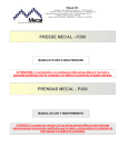
1
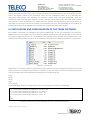
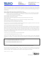
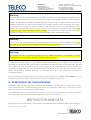
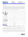
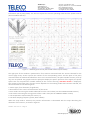
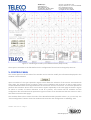
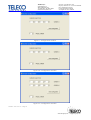
TELECO Spa
Via E.Majorana, 49
48022 LUGO (RA) Italy
Tel. 0545 25037 Fax 0545 32064
www.telecoshmsystems.com
Cap. Soc. € 120.000,00 int. vers.
Reg. Imp. Ravenna, C.F. e P.IVA 01117060390
R.E.A. di Ravenna N.121783
N. meccanografico RA 004167
VAT Registr. N. IT01117060390
I. INTRODUCTION
This manual describes the installation and use of the TGH04 software in a SHM602 Teleco SHM System.
TGH04 is an optional addition to any SHM602 system that runs on the TSD10 storage and control unit. It
has been designed to perform the visualization of the poles of the models computed by the TSM02 sensors
and the power spectrum associated to the measured acceleration signals. The TGH04 software does not
affect in any way the data acquisition process and cannot be used to modify the user selectable
parameters; these functions are performed by the TBH02 configuration and data acquisition software
distributed with every SHM602 system.
II. STRUCTURE OF THE SHM602 FILE SYSTEM
The measured acceleration data and the computed models are stored by the SHM602 system on a large
capacity USB storage unit (flash drive, hard drive etc.) that is automatically named by the operating system
as Hard Disk. The TBH02 software creates on this unit the directory log where the acceleration data
are stored in subdirectories whose name begins with net (e.g. net_000_20100728) while the models
are stored in subdirectories whose name begins with cov (e.g. cov_20100728). Every subdirectory
contains the data collected during one day. The model and data files have names given by progressive
numbers with the log suffix.
Hard Disk
net_000_20100728
15013.log
15014.log
.........
net_000_20100729
.........
................
.........
cov_2010728
102516.log
102516.log
..........
cov_2010729
..........
................
..........
log
Figure 1 – Structure of the data file system of the SHM602
The acceleration files are stored in binary format and the extraction of the stored measures can be
performed by means of the parsing software distributed with the SHM602 system. The models are stored
in text files with contents of the following type (not actual data; the parameters of the identified models
are stored with higher precision):
001 X 29 07 2010 10 34 170.15 44.24 -18.69 -59.48 -47.33 -7.38 26.05 26.21 18.73 6.91 -28.56 29 80
001 Y 29 07 2010 10 34 340.13 221.77 111.9 -20.25 -141.87 -216.55 -235.55 -185.64 -80.41 40.61 135.34 29 80
002 X 29 07 2010 10 34 224.01 100.72 19.36 -34.05 -77.79 -81.19 -56.13 -35.94 -10.83 15.19 30.12 29 80
002 Y 29 07 2010 10 34 185.47 76.90 5.45 -25.01 -26.50 -48.64 -81.70 -69.11 -13.11 33.79 34.37 29 80
………………………………………………………
Figure 2 – Structure of the model files
TGH04 – Rel. 2.2.01 – Page 1
www.telecogroup.com - [email protected]
TELECO Spa
Via E.Majorana, 49
48022 LUGO (RA) Italy
Tel. 0545 25037 Fax 0545 32064
www.telecoshmsystems.com
Cap. Soc. € 120.000,00 int. vers.
Reg. Imp. Ravenna, C.F. e P.IVA 01117060390
R.E.A. di Ravenna N.121783
N. meccanografico RA 004167
VAT Registr. N. IT01117060390
The total number of rows in every file is twice the number of connected sensors. The first number in every
row is the logical number of the associated sensor and the subsequent letter (X or Y) describes the
associated accelerometer. The following five numbers contain date and time information while the
subsequent eleven floating point numbers contain a compact information on the identified models whose
characteristics can be visualized by the TGH04 software. The last but one number is the temperature (°C)
measured by the sensor and the last number is the sampling rate (Hz). The knowledge of the structure of
the data file system of the SHM602 is not required for a proper operation of the system.
III. INSTALLATION AND CONFIGURATION OF THE TGH04 SOFTWARE
The TGH04 is delivered only configured for specific applications; all files are contained in the directory
TGH04 that must be copied in the root directory (Hard Disk) of the USB storage device connected to
the TSD10 storage and control unit. The number of files depends on the number of connected sensors; the
example that follows makes reference to an installation where 4 sensors TSM02 are present in the system.
Figure 3 – TGH04 files
While there is no need to modify or substitute any file to obtain a correct working of the software, it can be
useful to know the possibilities associated to variations. In this case the files that can be substituted by the
user (more about their role and possible substitutions in the following) are:
S1.gif
S2.gif
S3.gif
S4.gif
Torre_Ing.jpg
The file Config.txt is the configuration file. In this example its content is the following:
1,1,1,1,1,\Hard Disk\TGH04\S1.gif,TSM02,Floor 3,X: 120,Y: 270
2,1,2,1,2,\Hard Disk\TGH04\S2.gif,TSM02,Floor 4,X: 180,Y: 30
3,1,3,1,3,\Hard Disk\TGH04\S3.gif,TSM02,Floor 5,X: 0,Y: 90
4,1,4,1,4,\Hard Disk\TGH04\S4.gif,TSM02,Floor 6,X: 0,Y: 90
10
15000
Figure 4 – Example of the file Config.txt for a system with 4 sensors
TGH04 – Rel. 2.2.01 – Page 2
www.telecogroup.com - [email protected]
TELECO Spa
Via E.Majorana, 49
48022 LUGO (RA) Italy
Tel. 0545 25037 Fax 0545 32064
www.telecoshmsystems.com
Cap. Soc. € 120.000,00 int. vers.
Reg. Imp. Ravenna, C.F. e P.IVA 01117060390
R.E.A. di Ravenna N.121783
N. meccanografico RA 004167
VAT Registr. N. IT01117060390
The first set of rows concerns the implemented sensors (one row for every sensor, four in the example
above). The number of rows is, however, always a multiple of 4 because every page reports the data of 4
sensors; if the actual number of sensors is lower, virtual sensors will be inserted. The meaning of the data is
the following:
Field 1: Logical number of the sensor associated with the row
Field 2: Numbers of the pages (same number on rows 1-4, 5-8 etc.)
Filed 3: Number of the sensor associated with the page (the same sensor can be associated to more pages
and some sensors can be excluded. These visualization associations can be freely modified by the
user from the control panel of the FGH04.
Field 4: Number of the bus where the sensor is inserted
Field 5: Number of the sensor on the bus
Field 6: Path and name of the graphic file describing the physical allocation of the sensor
Field 7: Sensor type
Field 8: Floor of the building where the sensor is located (if meaningful, otherwise empty)
Field 9: Orientation of the X accelerometer of the sensor
Field 10: Orientation of the Y accelerometer of the sensor
The last but one row reports the default model order (possible values: 2,4,6,8,10). The order can be freely
modified by the user from the control panel of the FGH04.
The last row contains the update interval in milliseconds.
The file above informs the system that four sensors with logical numbers 1,2,3 and 4 are present. Only one
page can be visualized and this page will contain the data concerning all sensors. All sensors are inserted on
bus #1 where their numbers are again 1,2,3 and 4. The default order model is 10 and the update interval is
15s. It is worth noting that every model is obtained from the samples collected in 1 minute (1200 @ 20Hz,
2400 @ 40Hz and 4800 @ 80Hz); update intervals lower than 60s do not correspond, consequently, to any
increase in the information update.
Virtual sensors are associated with rows of the following type:
0,1,2,0,\Hard Disk\TGH04\S0.gif,None,None,X: 0,Y: 00
where only the page number and the logical number of one of the sensors are the only meaningful
information. For instance, an installation with two sensors could have a configuration file of the following
type:
1,1,1,1,1,\Hard Disk\TGH04\S1.gif,TSM02,Floor 3,X: 120,Y: 270
2,1,2,1,2,\Hard Disk\TGH04\S2.gif,TSM02,Floor 4,X: 180,Y: 30
0,1,1,0,0,\Hard Disk\TGH04\S0.gif,None,None,X: 0,Y: 0
0,1,2,0,0,\Hard Disk\TGH04\S0.gif,None,None,X: 0,Y: 0
6
60000
Figure 5 – Example of the file Config.txt for a system with 2 sensors
The two sensors have the logical numbers 1 and 2. Only one page can be visualized and this page will
contain the data concerning sensors 1 and 2 (twice). The sensors are inserted on bus #1 where their
numbers are again 1 and 2. The default order model is 6 and the update interval is 60s.
TGH04 – Rel. 2.2.01 – Page 3
www.telecogroup.com - [email protected]
TELECO Spa
Via E.Majorana, 49
48022 LUGO (RA) Italy
Tel. 0545 25037 Fax 0545 32064
www.telecoshmsystems.com
Cap. Soc. € 120.000,00 int. vers.
Reg. Imp. Ravenna, C.F. e P.IVA 01117060390
R.E.A. di Ravenna N.121783
N. meccanografico RA 004167
VAT Registr. N. IT01117060390
Warning
The user can edit the configuration file to change the graphic files describing the allocation of the
sensors or their orientation. He can also modify the value of the update interval. All other allowable
changes can be performed inside the TGH04. Improper variations to the configuration file can make the
TGH04 non operative; it is thus recommended to save a copy of this file before attempting any change.
It is important to note that the numbers inserted in the third field refer to the logical numbers of the
sensors and, consequently, cannot be greater than the total number of sensors in the system. The
insertion of larger values will lead to a crash of TGH04. The content of the third field, that controls the
information displayed in the pages, can be safely modified from the TGH04 control panel.
Warning
Every copy of the TGH04 software is delivered properly tailored for a specific SHM602 system. The
exchange of copies on different installations can lead to unsafe operations and violates licensing terms.
Warning
The TGH04 software is specifically designed for the TSD10 environment; its operation in other
environments (e.g. Windows XP, Vista etc. ) leads to improper results.
The files S1.gif, S2.gif, S3.gif etc. (the names in actual installations can be different) are graphic files
describing the allocation of the sensors and can be substituted with other files concerning images with the
same dimensions (134 x 96 pixels). The file Torre_Ing.jpg can be substituted with another graphic file
containing an image with the same dimension (200 x 193 pixels). If the new files have different names
and/or are located in different directories the corresponding field in the configuration file must be
accordingly changed.
Once that the files reported in Figure 3 have been copied in the directory Hard Disk\TGH04\ of the
TSD10 control unit, the TGH04 can be executed as any other Windows application.
IV. OPERATION OF THE TGH04 SOFTWARE
The TGH04, when executed, will search inside the directory Hard Disk\log\ for subdirectories whose
name begins with cov and will select the most recent one. Inside this subdirectory it will analyze all files
and select, to avoid access conflicts, the last but one.
If no subdirectories of the searched type are present or the most recent subdirectory contains less than 2
files, the program will display the following warning and wait for proper data:
This situation can be observed only if the TGH04 is executed before data collection and storage operations.
TGH04 – Rel. 2.2.01 – Page 4
www.telecogroup.com - [email protected]
TELECO Spa
Via E.Majorana, 49
48022 LUGO (RA) Italy
Tel. 0545 25037 Fax 0545 32064
www.telecoshmsystems.com
Cap. Soc. € 120.000,00 int. vers.
Reg. Imp. Ravenna, C.F. e P.IVA 01117060390
R.E.A. di Ravenna N.121783
N. meccanografico RA 004167
VAT Registr. N. IT01117060390
As soon as at least two valid files are stored in a subdirectory of the type cov_nnnnnn, a window of the
type displayed in Figure 7 will be visualized and updated according to the time interval inserted in the
configuration file.
It must however be observed that when the whole system is activated, the sensors TSM02 start a control
and self calibration procedure that leads, until completed, to the generation of non valid model and data
files. This phase lasts no more than 2-3 minutes and concerns only the initial activation of the system or a
variation in the configuration of the data acquisition parameters (that requires restarting the TBH02 for its
activation). If the TGH04 has been activated before the conclusion of these operations, it will recognize the
invalid data sets and generate a screen of the type reported in Figure 6 that informs that only sensor 2 is
operative while sensors 1, 3 and 4 have not yet concluded their initialization.
Figure 6 – Window generated by the TGH04 during the initial calibration of the sensors
The image in the upper left corner can be changed by the user (file Torre_Ing.jpg in this example)
while the description lines under it are part of the software tailoring. The same can be repeated for the
lines reporting the name of the licensee, the version of the software and its serial number.
The information reported under the control panel of the TGH04 concerns the name of the most recent
directory of models (cov_20100729), the name of the last file in this directory (150118.log), the number of
the current window and that of available windows (1 for both in this example), the display mode currently
selected (Data), the generation time and date of the file associated with the currently displayed
TGH04 – Rel. 2.2.01 – Page 5
www.telecogroup.com - [email protected]
TELECO Spa
Via E.Majorana, 49
48022 LUGO (RA) Italy
Tel. 0545 25037 Fax 0545 32064
www.telecoshmsystems.com
Cap. Soc. € 120.000,00 int. vers.
Reg. Imp. Ravenna, C.F. e P.IVA 01117060390
R.E.A. di Ravenna N.121783
N. meccanografico RA 004167
VAT Registr. N. IT01117060390
information (14:59, 29/7/2010). The last line reports the current operating mode and the update interval
(On line models and 15s).
Figure 7 – Window generated by the TGH04 software (Data mode)
The right part of the window is partitioned in four sections associated with the sensors selected for the
current page. Every section reports the number of the corresponding sensor and the plots of the poles
associated with the models identified from the X and Y accelerometers; the poles outside the unity circle (if
any) are not plotted. The graphs under the pole plots display the power spectrum of the signals; the power
spectra are not computed for unstable models (in this case the warning UNSTABLE MODEL is displayed).
The content of the lower part of every section depends on the working mode that has been selected; the
data mode leads to the following lines:
1: Sensor type, floor allocation (if significant)
2: Orientation of the X and Y accelerometers of the sensor
3: Error codes concerning the models obtained from the X and Y data (see the CONTROL PANEL section)
4: The codes concerning the energy levels of the X and Y data (see the CONTROL PANEL section)
5: The temperature measured by the sensor (°C)
6: The data sampling frequency (20Hz, 40Hz or 80Hz)
When the map mode is selected, the previous information is substituted with the maps describing the
allocation of the sensors, as shown in Figure 8.
TGH04 – Rel. 2.2.01 – Page 6
www.telecogroup.com - [email protected]
TELECO Spa
Via E.Majorana, 49
48022 LUGO (RA) Italy
Tel. 0545 25037 Fax 0545 32064
www.telecoshmsystems.com
Cap. Soc. € 120.000,00 int. vers.
Reg. Imp. Ravenna, C.F. e P.IVA 01117060390
R.E.A. di Ravenna N.121783
N. meccanografico RA 004167
VAT Registr. N. IT01117060390
Figure 8 – Window generated by the TGH04 software (Maps mode)
The maps are associate to the files defined in the configuration file and can be changed by the user.
V. CONTROL PANEL
The control panel on the left side of the window can be used to modify the information displayed in the
windows. The first button
opens a window of the type reported in Figure 9 that allows the selection of the sensors associated with
every page. The example shown in Figure 9 refers to an installation with 4 sensors so that a single screen
can be visualized and the most logical selection of the sensors concerns all sensors. It is however possible to
perform also selections where one or more sensors appear repeatedly in the same page as shown in Figure
10. When a number of sensors between 5 and 8 is present, two screens will be available and the
configuration file will look like that reported in Figure 11 where it can be observed that the sensors 1 and 2
have been inserted in both pages.
This window allows also to select the order of the identified models (possible values 2, 4, 6, 8 and 10). The
“Store Configuration” button closes the window and stores the new configuration in Config.txt.
TGH04 – Rel. 2.2.01 – Page 7
www.telecogroup.com - [email protected]
TELECO Spa
Via E.Majorana, 49
48022 LUGO (RA) Italy
Tel. 0545 25037 Fax 0545 32064
www.telecoshmsystems.com
Cap. Soc. € 120.000,00 int. vers.
Reg. Imp. Ravenna, C.F. e P.IVA 01117060390
R.E.A. di Ravenna N.121783
N. meccanografico RA 004167
VAT Registr. N. IT01117060390
Figure 9 – Configuration window
Figure 10 – Configuration window
Figure 11 – Configuration window
TGH04 – Rel. 2.2.01 – Page 8
www.telecogroup.com - [email protected]
TELECO Spa
Via E.Majorana, 49
48022 LUGO (RA) Italy
Tel. 0545 25037 Fax 0545 32064
www.telecoshmsystems.com
Cap. Soc. € 120.000,00 int. vers.
Reg. Imp. Ravenna, C.F. e P.IVA 01117060390
R.E.A. di Ravenna N.121783
N. meccanografico RA 004167
VAT Registr. N. IT01117060390
The button
allows to pass to the next screen (this operation is performed at the subsequent window update).
The button
allows to switch between the “Data” and the “Maps” operating modes.
The button
stops the selection of new data sets until it is clicked again.
The button
visualizes the help window reported in Figure 12 that explains the meaning of the error codes associated
with the data and the identified models.
Figure 12 – List of data and model error codes
Finally, the button
stops the execution of the program.
TGH04 – Rel. 2.2.01 – Page 9
www.telecogroup.com - [email protected]