1
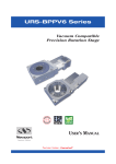
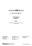
UTS Series
SP
E
CI
ANTE
NS
AR
ED
GU
High-Performance Precision
Translation Stages
F I C AT
IO
RoHS
Compliant
USER’S MANUAL
UTS Series
High-Performance Precision Translation Stages
Warranty
Newport Corporation warrants this product to be free from defects in
material and workmanship for a period of 1 year from the date of
shipment. If found to be defective during the warranty period, the product
will either be repaired or replaced at Newport’s discretion.
To exercise this warranty, write or call your local Newport representative,
or contact Newport headquarters in Irvine, California. You will be given
prompt assistance and return instructions. Send the instrument,
transportation prepaid, to the indicated service facility. Repairs will be
made and the instrument returned, transportation prepaid. Repaired
products are warranted for the balance of the original warranty period, or
at least 90 days.
Limitation of Warranty
This warranty does not apply to defects resulting from modification or
misuse of any product or part.
CAUTION
Warranty does not apply to damages resulting from:
CAUTION
Please return equipment in
the original (or equivalent)
packing.
You will be responsible for
damage incurred from
inadequate packaging if the
original packaging is not
used.
• Incorrect usage:
– Load on the stage greater than maximum specified load.
– Carriage speed higher than specified speed.
– Improper grounding.
¬ Connectors must be properly secured.
¬ When the load on the stage represents an electrical risk, it must
be connected to ground.
– Excessive or improper cantilever loads.
• Modification of the stage or any part thereof.
This warranty is in lieu of all other warranties, expressed or implied,
including any implied warranty of merchantability or fitness for a
particular use. Newport Corporation shall not be liable for any indirect,
special, or consequential damages.
No part of this manual may be reproduced or copied without the prior
written approval of Newport Corporation.
This manual has been provided for information only and product
specifications are subject to change without notice. Any changes will be
reflected in future printings.
EDH0220En1040 — 07/15
ii
UTS Series
High-Performance Precision Translation Stages
Table of Contents
Warranty .................................................................................................................ii
EC Declaration of Conformity...............................................................................v
Definitions and Symbols.......................................................................................vi
Warnings ...............................................................................................................vii
Cautions ...............................................................................................................viii
1.0
— Introduction .................................................................................1
2.0
— Description ...................................................................................2
2.1 Design Details ............................................................................................3
3.0
3.1
3.2
3.3
3.4
3.5
4.0
— Characteristics ............................................................................4
Definitions ..................................................................................................4
Mechanical Specifications .......................................................................5
Load Specification Definitions.................................................................5
Load Characteristics and Stiffness .........................................................6
Stage Weights ............................................................................................6
— Drive ................................................................................................6
4.1 DC-Motor Drive Version ...........................................................................6
4.2 Stepper Motor Drive Versions.................................................................6
5.0
5.1
5.2
5.3
5.4
5.5
5.6
5.7
6.0
6.1
6.2
6.3
6.4
7.0
— Motor ...............................................................................................7
Stepper Motor Characteristics................................................................7
Command Signals for Stepper Motors....................................................7
UE34CC Motor Characteristics................................................................7
Command Signals for the DC-Motor .......................................................7
Sensor Position..........................................................................................8
Feedback Signal Position for UTS-CC Stages .........................................8
Pinouts........................................................................................................9
— Connection to Newport Controllers ..............................10
Warnings on Controllers ........................................................................10
Connection...............................................................................................11
Cables .......................................................................................................11
MSCABLE-3 Cable....................................................................................12
— Connection to Non-Newport Electronics ....................13
7.1 Connections .............................................................................................13
iii
EDH0220En1040 — 07/15
UTS Series
High-Performance Precision Translation Stages
8.0
— Dimensions .................................................................................14
8.1 UTS-CC and UTS-PP Stages ....................................................................14
8.2 UTS-PPV6 Vacuum Compatible Stages .................................................15
9.0
— Accessories .................................................................................16
9.1 Top Plate ..................................................................................................16
9.2 Base Plates ...............................................................................................16
9.3 Right-Angle Brackets ..............................................................................17
10.0 — Maintenance ..............................................................................18
10.1 Maintenance ............................................................................................18
10.2 Repair .......................................................................................................18
10.3 Calibration ...............................................................................................18
Service Form .........................................................................................................19
EDH0220En1040 — 07/15
iv
UTS Series
High-Performance Precision Translation Stages
EC Declaration of Conformity
UTS Series
EC Declaration of Conformity
following Annex II-1A
of Directive 2006/42/EC on machinery
The manufacturer:
MICRO-CONTROLE Spectra-Physics,
9 rue du Bois Sauvage
F-91055 Evry FRANCE
Hereby declares that the machinery:
Description: " UTS"
Function: High-Performance Translation stages
Models: UTS50/100/150-CC/PP/PPV6
– the technical file of which was compiled by:
Mr Dominique DEVIDAL, Quality Director,
MICRO-CONTROLE Spectra-Physics, Zone Industrielle - B.P.29
F-45340 Beaune La Rolande France
– complies with all the relevant provisions of the Directive 2006/42/EC on machinery.
– complies with all the relevant provisions of the Directive 2014/30/EU relating to electromagnetic compatibility.
– was designed and built in accordance with the following harmonised standards:
NF EN 61326-1:2013 « Electrical equipment for measurement, control and
laboratory use – EMC requirements – Part 1: General requirements »
NF EN 55011:2010/A1:2011 Class A
– was designed and built in accordance with the following other standards:
NF EN 61000-4-2
NF EN 61000-4-3
NF EN 61000-4-4
NF EN 61000-4-5
NF EN 61000-4-6
ORIGINAL DECLARATION
Done in Beaune La Rolande on 26 June 2015
Dominique DEVIDAL
Quality Director
DC1-EN rev:A
v
EDH0220En1040 — 07/15
UTS Series
High-Performance Precision Translation Stages
Definitions and Symbols
The following terms and symbols are used in this documentation and also
appear on the product where safety-related issues occur.
General Warning or Caution
The exclamation symbol may appear in warning and caution tables in this
document. This symbol designates an area where personal injury or
damage to the equipment is possible.
The following are definitions of the Warnings, Cautions and Notes that may
be used in this manual to call attention to important information regarding
personal safety, safety and preservation of the equipment, or important
tips.
WARNING
Warning indicates a potentially dangerous situation which can result in
bodily harm or death.
CAUTION
Caution indicates a potentially hazardous situation which can result in
damage to product or equipment.
NOTE
Note indicates additional information that must be considered by the
user or operator.
European Union CE Mark
The presence of the CE Mark on Newport Corporation equipment means
that it has been designed, tested and certified as complying with all
applicable European Union (CE) regulations and recommendations.
Warnings and Cautions
ATTENTION
This stage is a Class A device. In a residential environment, this device
can cause electromagnetic interference. In this case, suitable measures
must be taken by the user.
EDH0220En1040 — 07/15
vi
UTS Series
High-Performance Precision Translation Stages
Warnings
WARNING
The motion of objects of all types carries potential risks for operators.
Ensure the protection of operators by prohibiting access to the dangerous
area and by informing the personnel of the potential risks involved.
WARNING
Do not use this stage when its motor is emitting smoke or is unusually
hot to the touch or is emitting any unusual odor or noise or is in any
other abnormal state.
Stop using the stage immediately, switch off the motor power and then
disconnect the electronics power supply.
After checking that smoke is no longer being emitted contact your
Newport service facility and request repairs. Never attempt to repair the
stage yourself as this can be dangerous.
WARNING
Make sure that this stage is not exposed to moisture and that liquid does
not get into the stage.
Nevertheless, if any liquid has entered the stage, switch off the motor
power and then disconnect the electronics from power supply.
Contact your Newport service facility and request repairs.
WARNING
Do not insert or drop objects into this stage, this may cause an electric
shock, or lock the drive.
Do not use this stage if any foreign objects have entered the stage.
Switch off the motor power and then disconnect the electronics power
supply.
Contact your Newport service facility for repairs.
WARNING
Do not place this stage in unstable locations such as on a wobbly table or
sloping surface, where it may fall or tip over and cause injury.
If this stage has been dropped or the case has been damaged, switch off
the motor power and then disconnect the electronics power supply.
Contact your Newport service facility and request repairs.
WARNING
Do not attempt to modify this stage; this may cause an electric shock or
downgrade its performance.
WARNING
Do not exceed the usable depth indicated on the mounting holes (see
section “Dimensions”). Longer screws can damage the mechanics or
cause a short-circuit.
vii
EDH0220En1040 — 07/15
UTS Series
High-Performance Precision Translation Stages
Cautions
CAUTION
Do not place this stage in a hostile environment such as X-Rays, hard
UV,… or in any vacuum environment.
CAUTION
Do not place this stage in a location affected by dust, oil fumes, steam or
high humidity. This may cause an electric shock.
CAUTION
Do not leave this stage in places subject to extremely high temperatures
or low temperatures. This may cause an electric shock.
• Operating temperature: +10 to +35 °C
• Storage temperature: -10 to +40 °C (in its original packaging)
CAUTION
Do not move this stage if its motor power is on.
Make sure that the cable to the electronics is disconnected before
moving the stage. Failure to do so may damage the cable and cause an
electrical shock.
CAUTION
Be careful that the stage is not bumped when it is being carried. This
may cause it to malfunction.
CAUTION
When handling this stage, always unplug the equipment from the power
source for safety.
CAUTION
When the carriage is in its end-of-run position, it is strongly recommended
not to go beyond this point as this may damage the stage mechanism.
CAUTION
Contact your Newport service facility to request cleaning and
specification control every year.
EDH0220En1040 — 07/15
viii
UTS Series
High-Performance Precision Translation Stages
High-Performance Precision Translation Stages
UTS Series
1.0 —Introduction
This manual provides operating instructions for the UTS series translation
stages.
• UTS-PP
• UTS-PPV6 (1)
• UTS-CC
1)
REMARK
Vacuum compatible stages to 10-6 hPa. In this case, the max. speed and
load capacity have to be divided by two.
UTS translation stages.
RECOMMENDATION
We recommend you read carefully the chapter “Connection to
electronics” before using the UTS stage.
UTS50PPV6.
1
EDH0220En1040 — 07/15
UTS Series
High-Performance Precision Translation Stages
2.0 —Description
Newport’s UTS series linear stages provide superior motion performance
in an enhanced, short, and low profile package. They use the an optimized
body, high-performance bearings and lead screw, and completely motor
configurations.
UTS linear stages are available in two configurations
The first version, utilizing a DC motor, features an ultra-high resolution
20,000 cts/rev. rotary encoder with index pulse for precision homing and
is the recommended choice for applications requiring accurate bidirectional positioning. For tightest position control, the rotary encoder is
directly mounted on the lead screw. This eliminates the majority of drive
train error sources that affect other stages with indirect position read-out.
A high-torque DC motor provides the highest dynamic speed control and
allows for linear speeds up to 40 mm/s. A 44:16 belt reduction between the
motor and the lead screw increases the available output torque, reduces
the servo sensitivity and ensures 0.3 µm incremental motion capability
with all Newport motion controllers and drivers.
The stepper motor version is a cost-effective solution for less demanding
applications. When used with our XPS, ESP301, or SMC100PP controllers
with high micro-stepping capability, low-noise operation and very small
incremental motions are guaranteed. The stepper motor versions do not
use encoders, instead, position is attained by the number of commanded
steps and micro-steps. For this purpose, the stepper motor is directly
attached to the lead screw with a proprietary bellow coupling with hightorsion stiffness and no gear or belt drive in between. The high output
torque of the stepper motor also minimizes the risk of lost steps and
provides optimum motion sensitivity with good linearity between
commanded micro-steps and the actual motion of the stage.
All UTS series linear stages feature all-steel construction with preloaded
linear ball bearing slides. Steel has an almost 3-times greater stiffness than
Aluminum, and provides the UTS stages comparable stiffness to the
popular ILS series, but in a much more compact and significantly lower
profile package. In addition, because the bearings, the body, the carriage
and the lead screw are all made of steel, the UTS has a completely
homogenized design minimizing thermal stress or thermal bending effects.
The result is more consistent performance than other Aluminum stage
designs.
Smooth motion is provided by a diamond-corrected lead screw and a
matched, precision lapped nut to ensure high position stability with high
vertical load capacity. The nut includes anti-backlash preloading and a
sophisticated decoupling system that prevents lead screw eccentricity
errors from affecting stage movement.
For XY configurations of UTS stages, use the M-CAP-M41 captive screws.
The same screws can also be used for bolting UTS stages directly to
custom mounting surfaces (access via thru-holes at the carriage). For
mounting UTS stages to optical tables, please use the base plate M-PBN12
(see page 13).
EDH0220En1040 — 07/15
2
UTS Series
High-Performance Precision Translation Stages
2.1
Design Details
Base Material
Bearings
Drive Mechanism
Drive Screw Pitch
Feedback
Stainless steel
Linear ball bearings
Precision ground backlash-compensated leadscrew with decoupling nut
2 mm
CC: Screw mounted rotary encoder
PP and PPV6: No feedback
Optical
Optical, at center of travel
DC Servo, Micro Stepper
3 m (included)
Limit Switches
Origin
Drive Type
Cable Length
NOTE
RoHS
This product complies with the RoHS directive
(Restriction of Hazardous Substances).
Compliant
3
EDH0220En1040 — 07/15
UTS Series
High-Performance Precision Translation Stages
3.0 —Characteristics
3.1
Definitions
Specifications of our products are established in reference to ISO 230
standard part II “Determination of accuracy and repeatability of
positioning numerically controlled axes”.
This standard gives the definition of position uncertainty which depends
on the 3 following parameters:
(Absolute) Accuracy
Difference between ideal position and real position.
On-Axis Accuracy
Difference between ideal position and real position after the compensation
of linear errors.
Linear errors include: cosine errors, inaccuracy of screw or linear scale
pitch, angular deviation at the measuring point (Abbe error) and thermal
expansion effects. All Newport motion electronics can compensate for
linear errors.
The relation between absolute accuracy and on-axis accuracy is as follows:
Absolute Accuracy = On-Axis Accuracy + Correction Factor x Travel
Repeatability
Ability of a system to achieve a commanded position over many attempts.
Reversal Value (Hysteresis)
Difference between actual position values obtained for a given target
position when approached from opposite directions.
Minimum Incremental Motion (MIM or Sensitivity)
The smallest increment of motion a device is capable of delivering
consistently and reliably.
Resolution
The smallest increment that a motion device can theoretically move
and/or detect. Resolution is not achievable, whereas MIM, is the real
output of a motion system.
Yaw, Pitch
Rotation of carriage around the Z axis (Yaw) or Y axis (Pitch), when it
moves.
The testing of on-axis accuracy, repeatability, and reversal error are made
systematically with test equipment in an air-conditioned room (20 ±1 °C).
A linear cycle with 21 data points on the travel and 4 cycles in each
direction gives a total of 164 points.
Guaranteed Specifications
Guaranteed maximum performance values are verified per Newport's A167
metrology test procedure. For more information, please consult the
metrology tutorial section in the Newport catalog or at www.newport.com
EDH0220En1040 — 07/15
4
UTS Series
High-Performance Precision Translation Stages
SP
E
CI
ANTE
NS
AR
ED
GU
3.2
F I C ATI O
Mechanical Specifications
Travel Range (mm)
Minimum Incremental Motion (µm)
Uni-directional Repeatability (µm)
Bi-directional Repeatability (2) (µm)
On-Axis Accuracy (2) (µm)
Maximum Speed (mm/s)
Pitch (2) (µrad) (5)
Yaw (2) (µrad) (5)
MTBF (h)
1)
2)
3)
4)
5)
UTS-CC
UTSPP; UTS-PPV6
100
150
50
100
150
0.3
0.3 (1)
1
1
3.5 or ± 1.75
6 or ± 3
4.5 or ± 2.25 5.5 or ± 2.75 6.5 or ± 3.25
5 or ± 2.5
7 or ± 3.5
8 or ± 4.0
40 (3)
20 (4)
75 or ± 37.5 100 or ± 50 120 or ± 60
75 or ± 37.5 100 or ± 50 120 or ± 60
50 or ± 25
70 or ± 35
90 or ± 45
50 or ± 25
70 or ± 35
90 or ± 45
20,000 with 5 kg load and 30% duty cycle
50
0.3 mm with XPS; 0.5 mm with SMC100PP or ESP301.
Shown are peak to peak, guaranteed specifications or ±half the value as sometimes shown. For the definition of typical specifications
which are about 2X better than the guaranteed values, visit www.newport.com for the Motion Control Metrology Primer.
With axial loads greater than 1 kg the maximum speed must be reduced to 20 mm/s.
10 mm/s for UTS-PPV6; 4 mm/s for UTS-PPV6 when used with SMC100PP.
To obtain arcsec units, divide µrad value by 4.8.
CAUTION
To reach specifications stated, stages must be fixed on a plane surface
with a flatness of 5 µm.
3.3
Load Specification Definitions
Normal Load Capacity (Cz)
Maximum load a stage can move while maintaining specifications.
This value is given with speed and acceleration specified for each stage,
and with a load perpendicular to bearings.
Max. Speed (mm/s)
Max. Acceleration (mm/s2)
UTS-CC
40
160
UTS-PP
20
80
UTS-PPV6
10
40
Axial Load Capacity (±Cx)
Maximum load along the direction of the drive train.
Off-Centered Load (Q)
Maximum cantilever-load a stage can move: Q ≤Cz ÷ (1 + D/50)
D:
Cantilever distance.
5
EDH0220En1040 — 07/15
UTS Series
High-Performance Precision Translation Stages
3.4
Load Characteristics and Stiffness
Z
D
Q
x
kα
Cz
kαy
Cz, Normal centered load capacity (N)
+Cx, Axial load capacity (N)
-Cx, Inverse axial load capacity (N)
Kax, Compliance in roll (µrad/Nm)
Kay, Compliance in pitch (µrad/Nm)
Kaz, Compliance in yaw (µrad/Nm)
Q, Off-center load (N)
Where D = Cantilever distance (mm)
Y
X
+Cx
–Cx
3.5
UTS-CC
UTS-PP
200
UTS-PPV6
100
50
10
10
15
15
Q ≤ Cz ÷ (1 + D/50)
Stage Weights
Weights indicated into the below table are average values without any
cable.
Travel Range (mm)
50
UTS-CC
6.2 (2.8)
UTS-PP & UTS-PPV6
6.4 (2.9)
3-meter MSCABLE-3 Cable
Weight [lb (kg)]
100
7.1 (3.2)
7.3 (3.3)
0.66 (0.3)
150
8.2 (3.7)
8.4 (3.8)
4.0 —Drive
4.1
DC-Motor Drive Version
Resolution
(µm)
UTS-CC
0.1
1)
4.2
EDH0220En1040 — 07/15
Motor
UE34CC
With axial loads greater than 1 kg the maximum speed must be reduced to
20 mm/s.
Stepper Motor Drive Versions
Micro-Step
Resolution (1)
(µm)
UTS-PP
0.1
UTS-PPV6
0.1
1)
Speed
(mm/s)
40 (1)
Speed
(mm/s)
20
10
Motor
UE34PP
UE41PPV6
When used with Newport motion controllers, the motor is driven in a
dynamic micro-stepping mode (software communication). In that case, the
mechanical sensitivity is approx. 1/100 of a full step.
6
UTS Series
High-Performance Precision Translation Stages
5.0 —Motor
5.1
Motor
UE34PP
UE41PPV6
Angle by Step
(°)
1.8
1.8
Stepper Motor Characteristics
RMS Current per
Phase (A)
0.71
0.85
5.2
Resistance
(Ω)
1.7
5.7
Inductance
(mH)
2.8
11.3
Newport
Utilization
Micro-step
Micro-Step
Command Signals for Stepper Motors
Phase 1
Direction +
Phase 2
Direction +
Direction –
5.3
Motor
UE34CC
Nominal
Voltage (V)
48
5.4
Motion
Direction +
UE34CC Motor Characteristics
Max. RMS
Current (A)
0.9
Max. Peak
Current (A)
1.8
Resistance
(Ω)
2.52
Inductance
(mH)
0.51
Command Signals for the DC-Motor
+ Motor
+V
– Motor
–V
Displacement
Direction +
+ Motor
+V
– Motor
–V
Direction –
Displacement
Direction +
Direction +
In the above drawings, + Motor signal is referred to – Motor signal.
➀ When the stage moves in + Direction, the + Motor voltage is higher than
– Motor voltage.
➁ When the stage moves in – Direction, the + Motor voltage is lower than
– Motor voltage.
7
EDH0220En1040 — 07/15
UTS Series
High-Performance Precision Translation Stages
5.5
Sensor Position
Home Position (Origin)
– EOR Limit
+ EOR Limit
Mechanical
Zero
}
Only
DC Versions
Index Pulse
Index Pulse
Stage Travel Range
Motion
Direction +
End-of-Run and Mechanical Zero are 5 V open collector type.
The Index Pulse provides a repeatable Home Position at ±1 step.
CAUTION
“End-of-Run” and “Mechanical Zero” are active signals and should not be
connected to any other source.
5.6
Feedback Signal Position for UTS-CC Stages
1
Encoder
Phase A
Encoder
Phase A
Encoder
Phase B
Encoder
Phase B
2
3
4
1
0
1
Direction +
0
1
0
1
Direction +
0
Direction –
Motion
Direction +
The incremental sensor consists of a optical scale and an encoder head.
When the carriages of the stage move, the encoder head generates square
signals in quadrature, sent to pins #19, #20, #23 and #24 of the SUB-D25
connector.
Newport
Stage
User
Encoder Phase A
Pin #19
Encoder Phase A
Pin #23
Encoder Phase B
Pin #20
Encoder Phase B
Pin #24
Index Pulse Phase I
Pin #15
Index Pulse Phase I
Pin #25
Pin #21
Pin #22
Output Signals
+5 V 5%
150 mA max.
0V
}
Encoders
& Sensors
Power Supply
“Encoder” and “Index Pulse” are “differential pair” (type RS-422) type
output signals. Using these signals permits a high immunity to noise.
Emission circuits generally used by Newport are 26LS31 or MC3487.
Reception circuits to use are 26LS32 or MC3486.
EDH0220En1040 — 07/15
8
UTS Series
High-Performance Precision Translation Stages
5.7
Pinouts
The SUB-D15 connection for UTS Series translation stages is given in the
following table:
UTS-CC
UE34CC
1
9
15
1
8
UTS-PP
UE34PP
N.C.
1
2
+ Motor
3
Mechanical Zero
4
5
UTS-PPV6
UE41PPV6
+ Phase 1
1
+ Phase 1
2
+ Phase 2
2
+ Phase 2
3
Mechanical Zero
3
Mechanical Zero
– End-of-Run
4
– End-of-Run
4
– End-of-Run
0V
5
0V
5
0V
6
Encoder Phase /A
6
N.C.
6
N.C.
7
Encoder Phase /B
7
N.C.
7
N.C.
8
Index Pulse /I
8
N.C.
8
N.C.
9
N.C.
9
– Phase 1
9
– Phase 1
10
– Motor
10
– Phase 2
10
– Phase 2
11
+ End-of-Run
11
+ End-of-Run
11
+ End-of-Run
12
+5 V
12
+5 V
12
+5 V
13
Encoder Phase A
13
N.C.
13
N.C.
14
Encoder Phase B
14
N.C.
14
N.C.
15
Index Pulse I
15
N.C.
15
N.C.
The SUB-D25 connection at the end of the cable is given in the following
table:
UTS-CC
UE34CC
14
25
1
13
UTS-PP
UE34PP
UTS-PPV6
UE41PPV6
1
N.C.
1
+ Phase 1
1
+ Phase 1
2
N.C.
2
N.C.
2
N.C.
3
N.C.
3
– Phase 1
3
– Phase 1
4
N.C.
4
N.C.
4
N.C.
5
+ Motor
5
+ Phase 2
5
+ Phase 2
6
+ Motor
6
N.C.
6
N.C.
7
– Motor
7
– Phase 2
7
– Phase 2
8
– Motor
8
N.C.
8
N.C.
9
N.C.
9
N.C.
9
N.C.
10
N.C.
10
N.C.
10
N.C.
11
N.C.
11
N.C.
11
N.C.
12
N.C.
12
N.C.
12
N.C.
13
Mechanical Zero
13
Mechanical Zero
13
Mechanical Zero
14
Shield Ground
14
N.C.
14
N.C.
15
Index Pulse I
15
N.C.
15
N.C.
16
0 V logic
16
N.C.
16
N.C.
17
+ End-of-Run
17
+ End-of-Run
17
+ End-of-Run
18
– End-of-Run
18
– End-of-Run
18
– End-of-Run
19
Encoder Phase A
19
N.C.
19
N.C.
20
Encoder Phase B
20
N.C.
20
N.C.
21
+5 V
21
+5 V
21
+5 V
22
0 V Encoder
22
0V
22
0V
23
Encoder Phase /A
23
N.C.
23
N.C.
24
Encoder Phase /B
24
N.C.
24
N.C.
25
Index Pulse /I
25
N.C.
25
N.C.
9
EDH0220En1040 — 07/15
UTS Series
High-Performance Precision Translation Stages
6.0 —Connection to Newport Controllers
6.1
Warnings on Controllers
Controllers are intended for use by qualified personnel who recognize
shock hazards and are familiar with safety precautions required to avoid
possible injury. Read the controller user’s manual carefully before
operating the instrument and pay attention to all written warnings and
cautions.
WARNING
Disconnect the power plug under the following circumstances:
• If the power cord or any attached cables are frayed or damaged in
any way.
• If the power plug is damaged in any way.
• If the unit is exposed to rain, excessive moisture, or liquids are spilled
on the unit.
• If the unit has been dropped or the case is damaged.
• If you suspect service or repair is required.
• Whenever you clean the electronics unit.
CAUTION
To protect the unit from damage, be sure to:
• Keep all air vents free of dirt and dust.
• Keep all liquids away from the unit.
• Do not expose the unit to excessive moisture (85% humidity).
• Read this manual before using the unit for the first time.
WARNING
All attachment plug receptacles in the vicinity of this unit are to be of
the grounding type and properly polarized.
Contact your electrician to check your receptacles.
WARNING
This product is equipped with a 3-wire grounding type plug.
Any interruption of the grounding connection can create an electric
shock hazard.
If you are unable to insert the plug into your wall plug receptacle,
contact your electrician to perform the necessary alterations to ensure
that the green (green-yellow) wire is attached to earth ground.
WARNING
This product operates with voltages that can be lethal.
Pushing objects of any kind into cabinet slots or holes, or spilling any
liquid on the product, may touch hazardous voltage points or short out
parts.
EDH0220En1040 — 07/15
10
UTS Series
High-Performance Precision Translation Stages
6.2
Connection
On each stage is represented a label which indicates its name and its serial
number.
WARNING
Always turn the controller's power OFF before connecting to a stage.
Stages may be connected to the rear panel motor connectors any time
prior to power-up with the supplied cable assemblies.
NOTE
These stages are ESP compatible. Enhanced System Performance is
Newport's exclusive technology that enables Newport ESP motion
controllers to recognize the connected Newport ESP stage and upload
the stage parameters. This ensures that the user can operate the motion
system quickly and safely.
6.3
Cables
Our stages are delivered with a MSCABLE-3 3-meter cable. This cable is
equipped with a SUB-D25M connector so it can be directly connected to
our controllers/drivers.
WARNING
The MSCABLE-3 cable supplied is not designed for using in a vacuum
environment. The customer has the responsibility to link the UTS-PPV6
stage to the bulkhead coupling with a vacuum compatible cable and
connect the cable supplied between the controller and the bulkhead
coupling (the SUB-D15 connector must be removed).
11
EDH0220En1040 — 07/15
UTS Series
High-Performance Precision Translation Stages
6.4
MSCABLE-3 Cable
2.24 (57)
DISCONNECTED
LOCKING
KNOBS
ø.24
(6)
CABLE
CONNECTOR
STAGE
SUB-D15 CONNECTOR SHOWN
DIMENSIONS IN INCHES (AND MILLIMETERS)
BENDING
STATIC CABLE: ≥.94 (24)
CABLE IN MOTION: ≥2.76 (70)
WARNING
This cable is shielded correctly. For a correct operation, make sure to
lock connectors (ground continuity provided by the cable).
For applications where the standard 3-meter cable (MSCABLE-3) included
with your stage is not adequate, Newport offers a 10-m longer length cable
(MSCABLE-10) designed to ensure the integrity of your positioning
application.
These cables are specially shielded and terminated with Newport’s
standard SUB-D15 and SUB-D25 connectors.
WARNING
Keep the motor cables at a safe distance from other electrical cables in
your environment to avoid potential cross talk.
EDH0220En1040 — 07/15
12
UTS Series
High-Performance Precision Translation Stages
7.0 —Connection to Non-Newport Electronics
7.1
Connections
WARNING
Newport is not responsible for malfunction or damage to a UTS stage
when it is used with non- Newport controllers.
WARNING
Newport guarantees “ ” compliance of the UTS stages only if they are
used with Newport cables and controllers.
Nevertheless, the figure below shows the wiring when a UTS stage is
used with non-Newport controllers.
SUB-D25M
Connector
SUB-D15F
Connector
UE34PP &
UE41PPV6
UE34CC
9
10
11
12
1
2
3
4
1
+ Phase 1
N.C.
9
– Phase 1
N.C.
5
6
7
8
2
+ Phase 2
+ Motor
10
– Phase 2
– Motor
3
13
6
14
7
15
8
11
4
12
5
Connector
Cap
Mechanical Zero (1)
N.C.
N.C.
N.C.
N.C.
N.C.
N.C.
+ End-of-Run (2)
– End-of-Run (2)
+5 V
0V
Mechanical Zero (1)
Encoder Phase A
Encoder Phase /A
Encoder Phase B
Encoder Phase /B
Index Pulse I
Index Pulse /I
+ End-of-Run (2)
– End-of-Run (2)
+5 V
0V
14
16
13
19
23
20
24
15
25
17
18
21
22
Connector
Cap
(1)
(2)
The Mechanical Zero logic signal is open collector type. It supports until 30 V and 10 mA.
Open collector type with a 5.6 V protective Zener diode.
Newport
Stage
Mechanical Zero:
Iin max.: 10 mA
V max.: 30 V
Newport
Stage
End-of-Run:
Iin max.: 16 mA
V max.: 5.6 V
5.6 V
If the “Mechanical Zero” output
is not used, a 1 kΩ/0.25 W
resistor must be connected
between pins #13 and #21.
“Encoder” and “Index Pulse” are “differential pair” (type RS-422) type
output signals. Using these signals permits a high immunity to noise.
Emission circuits generally used by Newport are 26LS31 or MC3487.
Reception circuits to use are 26LS32 or MC3486.
13
EDH0220En1040 — 07/15
UTS Series
High-Performance Precision Translation Stages
8.0 —Dimensions
8.1
4 HOLES M4 THD,
C’BORED FOR CAPTIVE SCREWS
ON SQR 2.48 (63)
.20
(5)
UTS-CC and UTS-PP Stages
4 HOLES M4 THD
ON SQR 1.34 (34)
DEPTH: .16 (4)
3.62
(92)
B
.76
(19.7)
2.26
(57.5)
2.99
(76)
4.13
(105)
SUB-D15 MALE
CONNECTOR
4 HOLES ø.30 (Ø 7.5)
TO ACCESS CAPTIVE SCREWS
USED FOR FIXING THE STAGE
1.57
(40)
9 HOLES M6 THD, .98 (25) SPACING
DEPTH: .39 (10)
UTS50
UTS100
UTS150
MODEL SHOWN: UTS100PP
3.07
(78)
1.26
(32) 1.24
(31.5)
A
7.24 (184)
9.21 (234)
11.18 (284)
B
3.54 (90)
4.53 (115)
5.51 (140)
UTS-CC & UTS-PP
1.41 (35.8) MAX.
.39
(10)
4.17
(106)
A
BOTTOM VIEW OF THE UTS100CC
4 HOLES M5 THD / h 92
DEPTH: .26 (7)
2.39
(109)
4 HOLES M4 THD, C’BORED FOR
CAPTIVE SCREWS ON SQR 2.48 (63)
.51
(13)
2.91
(74)
1.95
(49.5)
.26
(7)
2.44
(62) 2.91
(74)
.47 (12)
SUB-D15 MALE
CONNECTOR
4 HOLES ø.30 (Ø 7.5)
TO ACCESS CAPTIVE SCREWS
USED FOR MOUNTING ON THE CARRIAGE
UTS150PP
EDH0220En1040 — 07/15
3.23
(82)
UTS150CC
14
UTS Series
High-Performance Precision Translation Stages
8.2
4 HOLES M4 THD,
C’BORED FOR CAPTIVE SCREWS
ON SQR 2.48 (63)
.20
(5)
UTS-PPV6 Vacuum Compatible Stages
4 HOLES M4 THD
ON SQR 1.34 (34)
DEPTH: .16 (4)
3.54
(90)
B
2.54
(64.5)
2.99
(76)
4.13
(105)
SUB-D15 MALE
CONNECTOR
4 HOLES ø.30 (Ø 7.5)
TO ACCESS CAPTIVE SCREWS
USED FOR FIXING THE STAGE
1.50
(38)
9 HOLES M6 THD, .98 (25) SPACING
DEPTH: .39 (10)
UTS50PPV6
UTS100PPV6
UTS150PPV6
MODEL SHOWN: UTS100PPV6
A
7.24 (184)
9.21 (234)
11.18 (284)
B
3.54 (90)
4.53 (115)
5.51 (140
3.07
(78)
1.26
(32) 1.24
(31.5)
1.67 (42.3)
MAX.
8
A
4 HOLES M5 THD / h 92
DEPTH: .26 (7)
4 HOLES M4 THD, C’BORED FOR
CAPTIVE SCREWS ON SQR 2.48 (63)
.12 (3.15)
MAX.
.94
(24)
4 HOLES ø.30 (Ø 7.5)
TO ACCESS CAPTIVE SCREWS
USED FOR MOUNTING ON THE CARRIAGE
UTS50PPV6.
15
EDH0220En1040 — 07/15
UTS Series
High-Performance Precision Translation Stages
9.0 —Accessories
9.1
Top Plate
3.15
(80)
.24
(6)
2.76
(70)
4 HOLES C’BORED FOR
M4 SCREW ON SQR 1.34 (34)
9 HOLES 1/4-20 THD,
1.00 (25.4) SPACING
The UTS-TP top plate is necessary if you need an interface with an
imperial hole pattern. It must be to ordered separately.
9.2
Base Plates
METRIC MOUNTING:
4 HOLES ø.268 (Ø 6.8) ON (150 x 100)
ENGLISH MOUNTING:
4 HOLES ø.268 (Ø 6.8) ON 6 x 2
4 HOLES M4 THD
ON ø4.49
(Ø 114)
4.72
(120)
4 HOLES
M5 THD
ON SQ 3.62 (92)
4 HOLES M5 CLR
ON SQ 1.89 (48)
ø1.97
(Ø 50)
25°
5 HOLES M4 THD
AT 60°
ON ø3.62 (Ø 92)
4 HOLES M4 CLR
ON SQ 2.48 (63)
.314
(8)
6.69 (170)
The M-PBN12 base plate is used with UTS-CC and UTS-PP stages, whereas
the M-PBN12V6 plate must be used with UTS-PPV6 vacuum compatible
stages. Both versions must be to ordered separately.
UTS150CC and UTS50C translation stages
in XY configuration.
EDH0220En1040 — 07/15
16
UTS Series
High-Performance Precision Translation Stages
9.3
Right-Angle Brackets
4 HOLES ø.28 (7.2)
ON SQR 2.01 (51)
4 HOLES C’BORED
FOR M4 SCREW ON SQR 63
B
MODEL SHOWN: EQ100-S
DIMENSIONS IN INCHES (AND MILLIMETERS)
3.60
(91.5)
ø1.97 (50)
4.25 (108)
2.87 (73)
A
C
.24
(6)
.24 (6)
4.7 (119.4)
MODEL
EQ100-S
EQ100-L
A
5.31 (135)
8.46 (215)
B
5.14 (130.5)
5.67 (144)
C
4.13 (105)
6.85 (174)
The EQ100-S right-angle bracket mounts vertical UTS50 stages to a
horizontal UTS. The EQ100-SV6 vacuum compatible version must be used
with the UTS50PPV6 stage.
The EQ100-L right-angle bracket mounts vertical UTS100 and UTS150
stages to a horizontal UTS. The EQ100-LV6 vacuum compatible version
must be used with the UTS100PPV6 or UTS150PPV6 stage.
All these versions must be to ordered separately.
17
EDH0220En1040 — 07/15
UTS Series
High-Performance Precision Translation Stages
10.0 —Maintenance
RECOMMENDATION
It is recommended to contact our After Sales Service which will know to
define the appropriate maintenance for your application.
10.1
Maintenance
The UTS stage requires no particular maintenance. Nevertheless, this is a
precision mechanical device that must be kept and operated with caution.
PRECAUTIONS
The UTS stage must be used or stocked in a clean environment, without
dust, humidity, solvents or other substances.
RECOMMENDATION
It is recommended to return your UTS stage to Newport's After Sales
Service after every 2000 hours of use for lubrication.
If your stage is mounted on a workstation and cannot be easily
removed, please contact Newport's After Sales Service for further
instructions.
10.2
Repair
CAUTION
Never attempt to disassemble a component of the stage that has not
been covered in this manual.
To disassemble a non specified component can cause a malfunction of
the stage.
If you observe a malfunction in your stage, please contact us immediately
to arrange for a repair.
CAUTION
Any attempt to disassemble or repair a stage without prior
authorization will void your warranty.
10.3
Calibration
CAUTION
It is recommended to return your UTS stage to Newport once a year for
recalibration to its original specifications.
EDH0220En1040 — 07/15
18
Service Form
Your Local Representative
Tel.:
Fax:
Name:
Return authorization #:
(Please obtain prior to return of item)
Company:
Address:
Date:
Country:
Phone Number:
P.O. Number:
Fax Number:
Item(s) Being Returned:
Model #:
Serial #:
Description:
Reasons of return of goods (please list any specific problems):
19
EDH0220En1040 — 07/15
Visit Newport Online at:
w w w. n e w p o r t . c o m
North America & Asia
Europe
Newport Corporation
MICRO-CONTROLE Spectra-Physics S.A.S
1791 Deere Ave.
Irvine, CA 92606, USA
9, rue du Bois Sauvage
91055 Évry CEDEX
France
Sales
Sales & Technical Support
Tel.: (800) 222-6440
Tel.: +33 (0)1.60.91.68.68
e-mail: [email protected]
e-mail: [email protected]
Technical Support
Service & Returns
Tel.: (800) 222-6440
Tel.: +33 (0)2.38.40.51.55
e-mail: [email protected]
Service, RMAs & Returns
Tel.: (800) 222-6440
e-mail: [email protected]