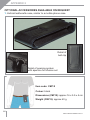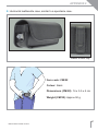
1
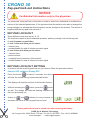
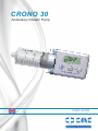
CRONO 30
Ambulatory Infusion Pump
USER GUIDE
Canè S.p.A. Medical Technology
Via Cuorgnè 42/a 10098 Rivoli (TO) Italy
Tel.+39 011 9574872 - Fax +39 011 9598880
www.canespa.it - [email protected]
Manual code: MAN 01/EN/03 CRONO 30
Publication date: 06/14
3
CRONO 30
Key-pad lock-out instructions
NOTICE
Confidential Information only to the physician
The pump has a key-pad lock-out function in order to avoid non authorised or accidental variations of the selected parameters; if it is opportune that the patient not be able to change the
pump settings it is advised that this information not be divulged to the him/her. The device is
supplied with the key-pad lock-out level 0.
KEY-PAD LOCK-OUT
Three different levels may be set: 0,1,2.
The levels are useful to avoid undesired operation, and they actually lock-out the key-pad.
• Level 0 means no restriction.
• Level 1 does not allow you to select:
- infusion time;
- enable/disable the end of infusion acoustic signal
• Level 2 does not allow you to select:
-- infusion time;
- partial volume;
- complete forced retraction of the pusher”;
- enable/disable the end of infusion acoustic signal
KEY-PAD LOCK-OUT SETTING
In order to set the level key-pad lock-out you need to follow the procedure below:
Pump in OFF condition. Display OFF.
Press the button
for about 5 seconds; the device
will utter the sound ticking of pressed push-button.
The display will read the number of delivered infusions.
Without releasing the
button, press the
button
as well. The display will read the flashing indication of
the level previously set.
Acting on
and
buttons you may increase or
decrease the value of the key-pad lock-out level.
PROG
PROG
PROG
The key-pad lock out level is stored even after removing the battery.
Canè S.p.A. Medical Technology
Via Cuorgnè 42/a 10098 Rivoli (TO) Italy Tel.+39 011 9574872 - Fax +39 011 9598880
www.canespa.it - [email protected]
WARNING
The pump has a function of key-pad lock-out in order to avoid non
authorised or accidental variations of the selected parameters; if
it is opportune that the patient not be able to change the pump
settings it is advised that this information not be divulged to the
him/her. The device is supplied with the key-pad lock-out level 0.
The information concerning the operation of key-pad lock-out and
key-pad unlock is provided separately from the current user guide
and is only for the physician.
Whenever the key-pad is on lock-out condition, any attempt to
modify the protected parameters make the display visualise the
padlock indicator ( ) accompanied by an intermittent acoustic signal.
Three different levels may be set: 0,1,2.
The levels are useful to avoid undesired operation, and they ac-
tually lock-out the key-pad.
• Level 0 means no restriction.
• Level 1 does not allow you to select:
- infusion time;
- enable/disable the end of infusion acoustic signal
• Level 2 does not allow you to select:
- infusion time;
- partial volume;
- complete forced retraction of the pusher”;
- enable/disable the end of infusion acoustic signal
CONTENTS
S E C T ION 1
Symbols and conventions................................................. Page 12
SEC TION 2
Introduction........................................................................ Page 13
WARNING: PRECAUTIONS FOR USE............................ Page 14
Further information............................................................ Page 14
SEC TION 3
Intended use...................................................................... Pump description............................................................... Infusion system................................................................. Technical characteristics................................................... Page 15
Page 17
Page 17
Page 18
SEC TION 4
Equipment supplied........................................................... Page 20
SEC TION 5
Pump parts........................................................................ Control buttons.................................................................. LED................................................................................... Liquid crystal display (LCD)............................................... Low battery indicator......................................................... Battery replacement.......................................................... Page 21
Page 22
Page 22
Page 23
Page 25
Page 26
SEC TION 6
Settings lock...................................................................... Page 28
SEC TION 7
Errors and anomalies........................................................ Page 29
Infusion set occlusion........................................................ Page 32
Post-occlusion bolus......................................................... Page 32
9
MAN 01/EN/03 CRONO 30 06/14
S ection 8
Factory settings................................................................. Page 33
INDICE
S ection 9
Quick reference................................................................. Page 34
Section 10
Pump initialisation............................................................. Page 36
Pump settings sequence with the pump in OFF or StoP condition Page 37
Setting of end of infusion acoustic signal.......................... Page 37
Setting the partial volume.................................................. Page 38
Setting the delivery time.................................................... Page 40
Switching on the pump...................................................... Page 41
The pump in ON condition................................................. Page 41
Priming the infusion line.................................................... Page 42
Switching off the pump...................................................... Page 43
Withdrawing the pusher..................................................... Page 44
Displaying the settings...................................................... Page 46
Resetting the number of infusion counter.......................... Page 47
Section 11
Reservoir parts.................................................................. Luer-lock cap functions...................................................... Infusion set........................................................................ Infusion set parts............................................................... Filter................................................................................... Identifying the filter components........................................ Preparation of the reservoir and connection to the pump... Connection of the reservoir to the pump........................... Infusion sites..................................................................... Preparing for the infusion.................................................. Page 48
Page 48
Page 49
Page 49
Page 49
Page 49
Page 50
Page 51
Page 53
Page 53
10
MAN 01/EN/03 CRONO 30 06/14
S E C T ION 12
How to use the accessories supplied................................ Page 56
SEC TION 13
GENERAL WARNINGS..................................................... Maintenance...................................................................... Storage.............................................................................. Disposal............................................................................. Expected pump life............................................................ Support ............................................................................. Guarantee ........................................................................ Declaration of conformity................................................... Page 57
Page 58
Page 58
Page 58
Page 58
Page 59
Page 60
Page 62
A P P E ND ICES
Appendix 1: ...................................................................... Appendix 2: ...................................................................... Appendix 3: ...................................................................... Appendix 4: ...................................................................... Appendix 5: ...................................................................... Appendix 6: ...................................................................... Appendix 7: ...................................................................... Appendix 8: ...................................................................... Page 64
Page 66
Page 68
Page 72
Page 73
Page 74
Page 76
Page 79
11
MAN 01/EN/03 CRONO 30 06/14
SECTION 1
SYMBOLS AND CONVENTIONS
To assist you in using the manual, the following symbols and conventions
have been used:
Triangle containing an exclamation mark
This “Warning” icon indicates something that must always be taken
into consideration for safe use of the pump.
Notepad
This icon indicates a “Notes” containing additional information or useful
tips about the use of the pump.
Flashing symbol
The graphic symbol
shown in the manual above the pictures of the
pump display, indicates that the information below it is flashing.
This manual is divided into 5 parts:
Part 1 (red): sections 1 to 7, general information, technical specifications
and warnings.
Par t 2 (blue): sections 8 to 10, describe the functions of the
CRONO 30 device.
Part 3 (orange): section 11, which describes the reservoir, the preparation and
insertion of the reservoir into the pump, the infusion sites and the preparation
for an infusion.
Part 4 (purple): sections 12 and 13, giving general warnings and a description
of the accessories supplied, as well as discussing maintenance, disposal and
support. It also details the guarantee and the declaration of conformity.
Appendices: pages 65 to 80.
12
MAN 01/EN/03 CRONO 30 06/14
SECTION 2
INTRODUCTION
Thank you for having chosen the ambulatory infusion pump, model: CRONO 30.
This manual has been prepared to enable you to make the best use of
the CRONO 30 pump, supplying information on the settings, safe use and
maintenance of the device.
If any of the information is not clear, or if you have any doubts or questions,
please contact the Customer Support Service of CANè S.p.A.
Incorrect use of the pump, or failure to follow the instructions and warnings
provided in this manual could cause serious injury.
The instructions provided herein are exclusively with respect to the
ambulatory infusion pump, model CRONO 30 and are intended for use by
the medical and paramedical personnel who need to set up the pump initially,
and subsequently by patients who are capable of managing their therapy
autonomously, or persons who are caring for patients.
The pump has a settings locking system (see Page 28) which stops the
settings from being modified by accident. The information relating to the
locking/unlocking of the settings lock is supplied at the back of this manual on
a plastic card.
The purpose of the settings lock is to avoid accidental or unauthorised
modification of the selected parameters. If it is considered inappropriate that
the patient should be aware of how to unlock the settings lock, the doctor and/
or other person who is assisting the patient should not supply this information.
The instructions in this manual are essential for the safe and correct use of
the pump. You are recommended to read the whole manual before starting to
use the device and to keep the manual handy for future reference.
The pump does not need to be installed, tested or activated.
Canè S.p.A. reserves the right to modify the hardware and software
specifications described in this manual at any time and without notice.
13
MAN 01/EN/03 CRONO 30 06/14
SECTION 2
NOTES
• Canè S.p.A. reserves the right to modify or update this manual at any time
and without notice.
• In order to make this manual as complete and accurate as possible,
please report any errors or omissions to the following e-mail address:
[email protected].
WARNING: PRECAUTIONS FOR USE
This pump is not recommended for independent use by patients who are unable
to follow and understand the instructions supplied in this manual or unable to
perform the basic operations and the regular maintenance of the pump.
FURTHER INFORMATION
For further information about the CRONO 30 pump, contact:
Servizio Assistenza Clienti (Customer Support Service)
Canè S.p.A. Medical Technology
Via Cuorgnè, 42/a 10098 Rivoli (Turin) - Italy
Tel. +39 011 957 4872 Fax +39 011 959 8880
Internet: www.canespa.it E-mail: [email protected]
14
MAN 01/EN/03 CRONO 30 06/14
SECTION 3
INTENDED USE
The CRONO 30 ambulatory infusion pump is designed for the subcutaneous
infusion of drugs for ferrochelation therapy.
Canè S.p.A. disclaims all responsibility for the administration of drugs by
other methods.
NOTE
The manufacturer holds itself responsible for the safety of patients
and the correct functioning of the device provided that it is used in
accordance with these instructions, and that any required repairs
and/or modifications are carried out exclusively by the said manufacturer.
WARNINGS
The use of incorrect settings and/or incomplete understanding of the
operational functions and of the alarms could cause serious harm to the
patient.
Before using the pump, evaluate whether its use is appropriate for the need
and for the patient, paying close attention to the following aspects:
- The technical specifications of the pump
- The infusion sets which will be used
-Whether you will be using multiple tube sets and clamps in the infusion line
- The cognitive and psycho-physical condition of the patient.
With respect to the clinical procedural aspects, which are the responsibility
of medical or paramedical personnel, the above list is supplied for example
purposes only and is not exhaustive.
The device must be used:
- Under the control of a doctor
-Adopting appropriate procedures and adequate measures when dealing
with patients who could suffer serious consequences (injury or death) in the
event of accidents and/or breakdowns which cause an interruption of the
administration of the drug.
15
MAN 01/EN/03 CRONO 30 06/14
SECTION 3
Do not prime the infusion line when it is connected to the patient, because
this could cause an overdose of the drug.
Before beginning an infusion, inspect the infusion line to ensure there are
no folds, clamps, or other occlusions in the line, and expel any air bubbles.
The precision and the time needed to indicate an occlusion could vary with
respect to the values indicated in this manual, depending on the type of
catheter, the infusion set and all the elements which comprise the infusion line.
If you have any suspicion that the pump has been in any way damaged, for
example by fluid penetration or having been dropped, contact the Customer
Support Service to check that the pump is functioning correctly. Do not use
a damaged pump.
If you have any doubts about the functioning of the pump or an error or
anomaly occurs, stop using the device and contact the Customer Support
Service.
Canè S.p.A. does not supply a replacement service for the pump during
the period needed for any repairs; such service should be supplied by the
relevant medical structure or the local distributor.
Any liquid on the pump casing must be removed immediately with absorbent
paper.
It is important to establish a procedure and/or alternative to pumped infusion,
in case the pump malfunctions. A valid alternative could be to have both
a second pump and an alternative backup system.
It is recommended that the individuals who assist and/or live with the pump
user know how the pump works and the information in this user manual.
It is important to stop using the device after the indicated service life has
expired and follow the instructions for its correct disposal.
16
MAN 01/EN/03 CRONO 30 06/14
SECTION 3
PUMP DESCRIPTION
CRONO 30 is an ambulatory infusion pump for controlled subcutaneous
administration of drugs.
CRONO 30 is a union of high technology and innovative design. Its reduced
dimensions and weight make it ideal for home use, giving the patient the
freedom to engage in everyday activities during the therapy.
CRONO 30 uses 30 ml dedicated reservoirs.
To improve the absorption of the drugs, CRONO 30 administers 33 µl per shot.
The pusher mechanism, which operates directly on the rubber piston of the
reservoir, enables the pump to combine high delivery pressure with excellent
precision while administering the drugs.
An innovative infusion control system allows the pump to automatically restart
and finish an infusion after an occlusion has been removed.
CRONO 30 is provided with a liquid crystal display (LCD) which shows
practical information to the doctor and patient about the settings, operations
and diagnostics of the pump.
INFUSION SYSTEM
The pump administers microdoses (shots) of 33 µl at intervals which depend
on the configured delivery time.
For example, if the delivery time is 1.00 h, with a 30 ml reservoir, the interval
between shots is approx 4 sec, whereas with a delivery time of 10.00 h and a
30 ml reservoir, the interval between shots is approx 40 seconds.
17
MAN 01/EN/03 CRONO 30 06/14
SECTION 3
TECHNICAL CHARACTERISTICS
Pump dimensions
80 x 47 x 30 mm (3.14 x 1.85 x 1.18 in).
Weight
125 g (4.40 oz.), including battery.
Battery
Lithium CR 123A 3V (battery life approx 200 infusions).
Single-use reservoirs
Dedicated, with a 30 ml capacity and a
“Luer-Lock” universal safety attachment.
Partial volume
From 1 to 30 ml in steps of 1 ml
Delivery timeProgrammable from:
1 h to 99 h in steps of 15 min.
Available priming volume
1.5 ml.
Flow rate precision
+/-2%.
Occlusion pressure
4,5 bar +/-2,0
Shot volume
33 microlitres (shot: quantity administered
for every rotation of the motor).
Occlusion signalling time
See Appendix 4.
Post-occlusion bolusApprox 1.2 ml.
Settings memory All settings are automatically stored in a flash memory which is retained even
if the device is left without a battery.
DisplayLiquid crystal display (LCD)
(1.1 x 2.8 cm; 0.43 x 1.0 in).
18
MAN 01/EN/03 CRONO 30 06/14
SECTION 3
Motor
Coreless DC motor, the rotation of which
is controlled by an infrared system.
Settings lock
Two configurable levels.
Electronic circuit with
Ensures a more reliable and safer infusion
twin microcontrollers system.
Safety circuits
These check that the device is functioning
correctly, intervening in the event of any
anomaly with sounds and messages on
the display.
Ingress protection rating
IP 42
Pump operating conditions+10°C / +45°C.
30% / 75% RH.
700 hPa / 1060 hPa.
Pump storage conditions-10°C / +60°C.
10% / 85% RH.
500 hPa / 1060 hPa.
19
MAN 01/EN/03 CRONO 30 06/14
SECTION 4
EQUIPMENT SUPPLIED
1. CRONO 30 ambulatory infusion pump.
2. Infuser carry-case (Code: VAL/01R).
3. Elastic belt (Code: CM/01).
4. Fabric pouch (Code: CM/02).
5. Collar strap (Code: CM/18D).
6. 2 Batteries (one of which is already inserted in the pump) Code: CR/123A).
7. Battery-cover opening tool.
8. User Manual.
2
8
4
7
6
1
5
3
20
MAN 01/EN/03 CRONO 30 06/14
SECTION 5
PUMP PARTS
Attachment for the reservoir wings
Led
Display
Supporting eyelets
of the supporting
cord
Pusher
Buttons
Anti-slip grooves
Battery
compartment
Serial no.
Quick reference
CE Marking
21
MAN 01/EN/03 CRONO 30 06/14
SECTION 5
CONTROL BUTTONS
There are 3 control buttons.
The buttons have a built-in safety delay: you must keep them pressed for
several seconds before the command takes effect. Use only your fingertips;
do not use sharp objects.
The buttons make a clicking sound when pressed.
A brief beep confirms that a command is being executed.
WARNING
The buttons have different functions according to which of the following
conditions the pump is in when they are pressed:
- OFF
- StoP
- ON
The functions of the buttons in the various different conditions mentioned
above are described in the quick reference instructions on Pages 34 and
35 and in Section 10.
LED
The red LED to the right of the display is switched on in the following
circumstances:
1 - When the battery is inserted during the pump verification checks, see Page 36.
2 - When an error has occurred, see Pages 29-30.
22
MAN 01/EN/03 CRONO 30 06/14
SECTION 5
LIQUID CRYSTAL DISPLAY (LCD)
The liquid crystal display uses text messages and icons to display practical
information about the settings, the operation being performed and any error
situations.
Four main digits
Arrow icon
Two secondary digits
Battery
condition
indicator
Lock
indicator
Drop icon
Four main digits of the display
Display principal information related to the values
of the settings, error information, etc.
Two secondary digits of the display
Display alternately:
• The volume remaining in the reservoir;
• Information related to the setting being displayed
in the four main digits;
• The unit of measurement of the setting being
displayed.
23
MAN 01/EN/03 CRONO 30 06/14
SECTION 5
“Low battery” indicator
Displayed when the battery is low
(see related section on Page 25).
Drop icon
Flashing: the hour and minute separator.
Arrow icon
The arrow indicates that the pump is being
programmed.
PROG
Minute indicator
Flashes when the remaining delivery time is
expressed in minutes (time left is less than 60
minutes).
Lock indicator
Indicates that the settings are locked (L1); i.e. they
can be viewed but cannot be changed.
24
MAN 01/EN/03 CRONO 30 06/14
SECTION 5
LOW BATTERY INDICATOR
The appearance of the “LOW BATTERY” alert (not flashing)
on the display indicates that the battery is low.
If the alert remains displayed for several consecutive
infusions, the “SPENT BATTERY” message is displayed,
accompanied by a beep repeated approximately every 10
seconds.
In these circumstances the pump can no longer be used
and the battery must be replaced.
During battery replacement, when in the OFF or StoP conditions, the pump
retains the current settings and the position of the pusher in its memory.
If the battery needs to be changed during an infusion the pump must be in the
StoP condition.
If the battery is removed with the pump in the ON condition, the pump is
automatically re-initialized, i.e. the pusher is withdrawn and repositioned to
start an infusion, displaying OFF on the display.
WARNINGS
• Do not use rechargeable batteries.
•Using other types of battery than lithium CR 123 A batteries could cause the
pump to malfunction.
•The battery life can be influenced by the age of the battery and the temperature
and circumstances of its use and storage.
• Ensure you always have a replacement battery available for use.
•If the pump is left inactive for long periods (1-2 months or more), you are
advised to remove the battery.
NOTES
• After you have inserted the battery, the pump runs a self-diagnosis test
during which it will emit brief audio signals and display all of the icons and
indicators.
• When you have finished changing the battery, check that the compartment
is properly closed.
25
MAN 01/EN/03 CRONO 30 06/14
SECTION 5
BATTERY REPLACEMENT
Use a 3 Volt Lithium battery, model 123 A.
To replace the battery, ensure that the pump is switched off (the display
showing OFF or StoP), and then proceed as follows:
1. Open the battery compartment using the PID battery tool for this purpose.
2. Pull out the cover.
3. Use the small ribbon strap (which lies under the battery) to facilitate the
removal of the battery.
4. Remove the discharged battery and discard it properly.
5. Insert the new battery checking that it is in the correct position and that
the ribbon strap is under the battery.
6. After having installed the battery, close the cover.
NOTES
In the event that it is not possible to remove the battery using the ribbon strap
do not use an object to lever out the battery, but proceed as follows:
• Hold the pump and the compartment cover firmly in one hand.
• Strike the palm of your other hand with the pump to jolt the battery from the
compartment.
•
The cover is supplied with a gasket which must remain in position
as indicated in the illustration.
Gasket
26
MAN 01/EN/03 CRONO 30 06/14
SECTION 5
CRONO
CRONO
PID
PID
CR
CRO
ONNO
O PI
PID
D
1
2
3
4
5
6
27
MAN 01/EN/03 CRONO 30 06/14
SECTION 6
SETTING LOCK
The CRONO 30 pump has 3 access configurations:
- L0 (unlocked): in this configuration you can use the control
buttons to access all of the settings and parameters and
control all of the operational functions.
PROG
- L1 (locked): in this configuration you can use the control
buttons to control the operational functions (switching on,
priming and switching off) but cannot modify any of the
settings (the delivery time, enabling/disabling the end of
infusion acoustic signal); when the pump is set to L1 the
display shows the lock indicator .
- L2 (locked): in this configuration the keyboard allows the
control of operating functions (on/off, prime) but not the
setting of parameters (delivery time, the partial volume,
pusher withdrawal, enabling/disabling the end of infusion
acoustic signal). When L2 is selected the display shows
the padlock symbol .
PROG
PROG
Before attempting to modify any of the settings, ensure
that the selected access level of the pump is L0 (OFF
symbol).
WARNINGS
• This access level for the functions remains in the memory even if the battery
is removed.
• When the settings access is L1 (locked), any attempt to access the locked
options will cause the pump to beep intermittently and display the “lock”
indicator.
•T
he information relating to the locking/unlocking of the settings lock is supplied
at the back of this manual on a plastic card and is only for use by a doctor.
28
MAN 01/EN/03 CRONO 30 06/14
SECTION 7
ERRORS AND ANOMALIES
AUDIBLE
SIGNAL
ERROR
DESCRIPTION
CORRECTIVE
ACTION
Brief beep.
Operation not allowed
---
Continuous tone and
flashing LED.
Critical problem in the
safety system.
Press the
button
Beep repeated every
10 sec approx.
Anomaly in the motor
circuit.
Press the
button
Beep repeated every
10 sec approx.
Mechanism of the
pusher blocked while
withdrawing (could be
caused by a foreign
body preventing its
movement).
Eliminate the cause
and initialize the pump.
Beep repeated every
10 sec approx.
Pusher mechanism
blocked.
Beep repeated every
10 sec approx.
Motor anomaly.
Beep repeated
every 10 sec
approx. (possibly
accompanied by
flashing LED).
Communication error
between the two
microcontrollers.
DISPLAY
Press the
button
Initialize the pump.
Press the
button
29
MAN 01/EN/03 CRONO 30 06/14
SECTION 7
DISPLAY
AUDIBLE
SIGNAL
ERROR
DESCRIPTION
CORRECTIVE
ACTION
When a battery is inserted
and at the start of every
infusion, the pump
performs a check of the
settings in the memory. If
Beep repeated every
an error is found, the value
10 sec approx.
in error is replaced by the
default value, the pump
motor is locked and the
error is indicated both on
the display and audibly.
Initialize the pump.
Beep repeated every
10 sec approx.
Anomaly in the safety
circuit which drives the
pump motor. If an error is
found, the pump locks and
the error is indicated.
Initialize the pump.
Beep repeated every
10 sec approx.
Anomaly in the pusher
mechanism.
Initialize the pump.
Beep repeated every
10 sec approx.
Mechanism blocked
because of an occlusion in
the infusion line.
Eliminate the cause
and press the
button.
See Page 32.
30
MAN 01/EN/03 CRONO 30 06/14
SECTION 7
WARNINGS
•F
ollowing the display of error message Er,8 and the successive initialisation,
the system reverts to the factory settings (see Page 33): in this event the
pump settings prescribed by the doctor should be re-entered.
• Error messages Er,2 and Er,7 are accompanied by the flashing red LED.
NOTES
• The displayed error messages (from Er,2 to Er,11 and OCCL) are
accompanied by a beep and the system stops.
•T
o initialize the device, remove the battery and reinsert it after 10/15 sec. If
the error is detected again after the corrective action or initialisation of the
device, contact the Canè S.p.A. Technical Support Service.
31
MAN 01/EN/03 CRONO 30 06/14
SECTION 7
INFUSION SET OCCLUSION
The pump is designed to recognize when the administration
of a drug has been interrupted by external means, such
as, for example, the kinking of the infusion set tube and
consequent occlusion.
An occlusion can be resolved in two ways:
1° - automatically by the pump, which attempts to continue
every two minutes;
2° - if the pump's automatic attempts do not work, you
must intervene and remove whatever was causing
the occlusion. Then re-start the infusion manually by
button.
pressing the
NOTES
•T
he cause of the occlusion is to be found along the infusion line and at the
point of injection.
o avoid or reduce the incidence of occlusions, you are advised to use an
•T
infusion set with anti-kinking tubes.
POST-OCCLUSION BOLUS
The occlusion alarm is given when the pump detects excessive back pressure
in the infusion line. This back pressure must be removed without accidentally
releasing a post-occlusion bolus, which could cause serious harm to the patient.
The volume of a post occlusion bolus of the CRONO 30, considering the
pump-syringe set only, is approximately 1.2 ml.
WARNINGS
• The volume of the bolus released after an occlusion can vary, depending
on the type of catheter, the infusion set and all the other components that
comprise the infusion line.
• Another element that could affect the volume of the released bolus after an
occlusion is the presence of any air in the system.
• After the occlusion alarm is given, disconnect the infusion set from the patient
to avoid a post-occlusion bolus being administered to the patient.
32
MAN 01/EN/03 CRONO 30 06/14
SECTION 8
FACTORY SETTINGS
The pump is supplied with the following default settings:
Reservoir 30 ml
End of infusion acoustic signal AL on (active)
Lock level set
Delivery time
L0 (unlocked)
Number of infusions
0
10 h
33
MAN 01/EN/03 CRONO 30 06/14
SECTION 9
QUICK REFERENCE
The buttons have a built-in safety delay: you must keep them pressed for
several seconds before the command takes effect.
These quick reference instructions are not an alternative to reading the
information in this manual, but give a basic and rapid summary of the pump’s
functions.
BUTTONS
Battery insertion
DISPLAY
• Self-diagnosis test
• Automatic positioning of the pusher
• Automatic switch-off
BUTTONS
PROGRAMMING
DISPLAY
PUMP SET TO OFF
Programming conditions:
- Pump switched off
- Beginning of a new infusion
- Settings lock unlocked.
1st press
• Selection of end of acoustic signal
(this parameter can always be programmed)
2nd press
• Partial dose volume programming
(also availlable in L1)
/
• Decrease/Increase the preceding parameter
values
PROG
PROG
PROG
NUMBER OF INFUSIONS
press for 4
seconds
Number of infusions (PC: Partial Counter)
SWITCHING ON
• Switching on the pump
• Priming phase
• Start of infusion
34
MAN 01/EN/03 CRONO 30 06/14
SECTION 9
BUTTONS
PRIMING
DISPLAY
• Priming (max 1.5 ml)
keep pressed
and
• Switching off the pump
press
contemporaneously
PROGRAMMING
PUMP SET TO ON
• Delivery time
• Setting of infusion time (keypad unlocked):
PROG
/
- from 1 h to 99 h in steps of 15 minutes
Decrease/increase
time
SWITCHING OFF THE PUMP / EARLY WITHDRAWAL OF THE Pusher
and
• Switching off the pump
END OF INFUSION
press
contemporaneously
and
• Interruption of an active infusion, withdrawing the pusher
press
contemporaneously
to the start position of the infusion
BUTTONS
END OF INFUSION
DISPLAY
• End of the infusion
• Automatic repositioning of the pusher to the starting
position
• Automatic switch-off
35
MAN 01/EN/03 CRONO 30 06/14
SECTION 10
PUMP INITIALISATION
When you insert the battery, the pump runs the initialization
sequence, during which it:
1. Runs a self-diagnosis test, emitting a series of brief
beeps, flashing the red LED and displaying all the
indicators and icons on the screen;
2. At the end of the self-diagnosis test the pusher is
withdrawn; (if the battery was removed after an error or
with the pump in ON).
3. When the pusher has been fully withdrawn the display
shows OFF.
NOTES
• The pump is supplied with a new battery already inside the pump.
• For instructions on how to install the battery, see Page 26.
•You are recommended to initialize the pump if it is left unused for a long
period (more than 1 - 2 months) and the battery is not removed.
WARNING
The setting of the pump is the responsibility of the doctor, who will choose
the parameter values best suited to the therapy required for the patient.
36
MAN 01/EN/03 CRONO 30 06/14
SECTION 10
PUMP SETTINGS SEQUENCE WITH THE PUMP IN OFF or StoP
CONDITION
To change the settings the pump must:
• be in the OFF or StoP condition
• have the settings lock off (i.e. set to L0).
SETTING OF END OF INFUSION ACOUSTIC SIGNAL
While the display is showing the type of reservoir
1. selected, press the
button: the pump enters the mode
for selecting the end of infusion acoustic signal;
2. W
hen the value flashes, select a new value using the
and
buttons.
Selecting oFF disables the end of infusion sound.
Selecting on activates the end of infusion acoustic signal,
which will sound 5 min and 10 min before the end of the
infusion;
PROG
PROG
3. D
o not press any button for 10 seconds, and the setting
phase will end. The flashing displayed value becomes
fixed and then OFF or StoP is displayed;
button before OFF is displayed (while the
4. P
ress the
value of the end of infusion sound is still flashing) to pass
to the setting of the successive parameter: SETTING THE
PARTIAL VOLUME.
PROG
NOTES
• Setting the reservoir type, the end of infusion sound and the partial dose
volume is only possible when the settings are unlocked (L0).
• When the settings lock is on (L1), if any attempts are made to change the
parameter then the display will show the flashing lock symbol and beep
several times.
37
MAN 01/EN/03 CRONO 30 06/14
SECTION 10
Setting the partial volume
The partial volume function is used when the therapy requires an infusion with
less than 30 ml.
The partial volume can be set from 1 cc to 30 cc in 1 cc increments.
Access the setting of this parameter by pressing the
button again, while
the parameter value is still flashing. The partial volume can be set only before
the start of a new complete or partial infusion.
Proceed as follows:
1. T
he display shows a flashing value for the volume,
preceded by cc, which indicates the unit of volume
(1 cc = 1 ml);
PROG
2. P
ress the
button to decrease the value, and the
button to increase it. Each change is indicated by a beep;
PROG
3. Do not press any button for 10 seconds and the setting
phase will end. The display will show P,cc;
4. The pusher is automatically positioned at the configured
partial volume value. An intermittent beep is emitted while
it does so, and the pump displays -- in real time -- the
actual volume corresponding to the pusher position;
5. When the pusher is in the correct position the display
changes to OFF.
38
MAN 01/EN/03 CRONO 30 06/14
SECTION 10
NOTES
• The partial volume setting is automatically stored in the pump’s memory.
• At the end of the infusion, the pusher returns to the position corresponding
to the partial volume setting.
• The partial volume setting can be interrupted by pressing the
and
buttons
simultaneously.
- if the pusher is still advancing, the pump switches off (the display shows StoP)
and the pusher remains where it was when the infusion was interrupted: the
partial volume setting is not stored and the previous value remains in memory.
- if, however, the pusher was in the process of being withdrawn, the display
alternates between OFF and P,cc. The only possible operation is to continue
button. The pusher withdraws
the withdrawal of the pusher, by pressing the
to the position of the partial volume setting.
•T
he partial volume can only be programmed at the start of a new infusion.
WARNINGS
•This operation must not be carried out with the infusion set connected to
the patient.
•A partial volume cannot be set while an infusion is in progress.
•The partial volume setting remains in the pump’s memory even if the
battery is removed.
• If the battery is removed when the pump is set to OFF/StoP, the partial
volume remains in the memory and the pusher is not withdrawn.
• If the battery is removed when the pump is set to ON, the pusher returns to the infusion start position for recalibration, and then repositions itself at the stored partial dose volume.
39
MAN 01/EN/03 CRONO 30 06/14
SECTION 10
SETTING THE DELIVERY TIME
The delivery time can be set from 1 h to 99 h, in increments of 15 minutes.
Procedure:
1. Push the
button to switch on the pump.
2. The pump enters the prime function.
3. Push the
: the infusion begins.
4. Push the
button to program the delivery time: the time
shown on the display begins to flash.
5. While the time is flashing it is possible to decrease the
value with the
button, and increase it using the
button. Holding either of the buttons down causes the time
to change more rapidly.
PROG
If no button is pressed for 10 seconds the display stops
flashing.
NOTES
• The delivery time is automatically stored by the pump.
• Holding either of the buttons down causes the delivery time to change more
rapidly.
• If either of the keypad lock levels (L1 or L2) is active, each time an attempt
is made to change the parameter the padlock symbol flashes and the bumps
emits a series of acoustic signals.
40
MAN 01/EN/03 CRONO 30 06/14
SECTION 10
SWITCHING ON THE PUMP
From the OFF condition, press the
will give a brief beep and display:
button. The pump
•P
r (priming function); the display shows Pr. There are three
options (see Page 42):
a. Postpone the priming.
b. Cancel the priming.
c. Perform the priming.
• Having carried out the priming, or if the pump is turned on
to resume the infusion from the StoP condition, the display
will show the delivery time.
THE PUMP IN ON CONDITION
When the pump is in action, the display shows the delivery
time counting down at 1 minute intervals to the end of the
infusion.
WARNINGS
Before starting an infusion:
• Inspect the infusion line to ensure there are no folds, clamps, or other
occlusions in the line.
• Expel any air bubbles.
41
MAN 01/EN/03 CRONO 30 06/14
SECTION 10
PRIMING THE INFUSION LINE
The priming function allows filling the infusion set tube with the drugs contained
in the reservoir.
The volume available for priming is 1.5 ml.
The priming function is enabled when the device is switched on and the pusher
is in the infusion start position, regardless of whether the settings lock is on.
The priming procedure is as follows:
1. Turn on the device by pressing the
button;
2. The display shows Pr. There are three options:
a. Postpone the priming.
b. Skip the priming.
c. Perform the priming.
a. Postpone the priming
Wait 10 seconds, the pump will turn OFF automatically.
b. Skip the priming
button: the pump begins the infusion and
Press the
the display shows the time remaining until the end of the
infusion.
c. Perform the priming
button: the pump delivers
Press and hold down the
the priming dose until you release the button. The display
then shows a flashing letter Pr in the secondary digits,
followed by the number of ml delivered. When the button
is released, the display shows Pr. The procedure can be
repeated up to a maximum release of 1.5 ml.
Proceed until the infusion set is completely full and a few
drops of the drugs leak out of it.
42
MAN 01/EN/03 CRONO 30 06/14
SECTION 10
NOTES
• If you keep the
button pressed the pump delivers the priming dose,
giving an acoustic signal every consecutive delivery of 0.5 ml
(i.e. 0.5 – 1.0 – 1.5 ml).
• If, after the priming indication is displayed, the buttons are not pressed again
for 10 seconds, the display shows OFF.
button. The
• The priming function can be interrupted by releasing the
display shows Pr again, and you again have the choice of postponing,
skipping (to start the infusion) or performing the priming function, as
described above.
WARNINGS
• Do not prime the infusion set with the tube connected to the patient.
• The priming function must only be performed with the reservoir attached to
the infusion set before inserting the needle into the infusion site.
• Before beginning an infusion, check that there are no air bubbles in the
infusion line, expelling any that are found. Alternatively, use a vented filter.
SWITCHING OFF THE PUMP
To switch off the pump during an infusion, press the
and
buttons simultaneously; the display will show StoP.
the
If the pump is switched off during an infusion, the device
will emit a series of 10 short beeps every 10 seconds, and
the display will flash the StoP message. To interrupt the
audible signals, press the
button. These indications will
be repeated each time the pump is switched off during an
infusion.
43
MAN 01/EN/03 CRONO 30 06/14
SECTION 10
WITHDRAWING THE Pusher
1. Stopping an infusion before the end
This function allows the interruption of an active infusion, withdrawing the
pusher to the start position of the infusion.
To stop an active infusion, do the following:
• Turn off the pump by pressing the
and
buttons
simultaneously.
and
buttons simultaneously: the display
ress the
•P
shows End for 10 seconds and then begins to withdraw
the pusher.
• During the 10 seconds that the display shows End the
withdrawal request may be cancelled by pressing the
buttons together.
and
2. Withdrawal of the pusher at the end of the infusion
If AL is active, ten minutes before the end of the infusion the
device emits an intermittent acoustic signal for 2 seconds.
The same signal is repeated twice 5 minutes before the end
of the infusion, and at the end of the infusion a continuous
acoustic signal is emitted and the the display shows the
“End” message.
The pusher remains stationary at the end-infusion position
for around 10 seconds, after which it begins to withdraw
until it reaches the start-infusion position.
When the withdrawal is complete, the display shows OFF
and the pump is ready for a further infusion.
Pusher in motion
While the pusher is in the process of being withdrawn,
the display shows the “pusher continuous withdrawal”
indication.
44
MAN 01/EN/03 CRONO 30 06/14
SECTION 10
NOTES
• The function to withdraw the pusher can be interrupted
and
buttons together. The display
by pressing the
then alternates between End and OFF. At this point only
the
button is active. When pressed again the pump
recommences the withdrawal of the pusher.
• The duration of the withdrawal of the pusher is approximately 6 minutes for
a volume of 30 cc; the duration is proportionally shorter for smaller volumes.
WARNING
Do not remove the reservoir until the pusher has been withdrawn to the infusion
start position.
45
MAN 01/EN/03 CRONO 30 06/14
SECTION 10
DISPLAYING THE SETTINGS
This function displays the programmed pump settings.
To display the pump settings, the pump must be set to OFF or StoP.
If the settings are displayed when the settings lock is set to L0 (settings lock
off) the settings flash and can be modified. If the settings are displayed when
the settings lock is set to L1 or L2 (settings lock on, with the display showing
the “lock” indicator), the settings do not flash and cannot be modified.
Proceed as follows:
button for approx 1 second: the display will
1. P
ress the
show the menu for selecting the end of infusion acoustic
signal;
button again and the display will show the 2.Press the
selected partial volume; (in L2 only the visualization is possible);
PROG
3. Do not press any button for 5 seconds, and the setting phase will end. The display will show OFF or StoP.
46
MAN 01/EN/03 CRONO 30 06/14
SECTION 10
Resetting the NUMBER OF infusion counter
The device contains two infusion counters: one which is a partial count of
infusions and can be reset, and another which shows the total number of
infusions effected.
To reset the number of infusion counter, proceed as follows:
button for approx 4 seconds, until the display
1 - Press the
shows the counter of infusions PC (Partial Counter);
2-W
ithout releasing the
button, press the
button:
the partial counter of infusions begins to flash;
3-P
ress the
button once more to invoke the programming
mode (the down arrow is displayed);
4 - Press either the
or the
buttons to set the or partial
counter of infusions to zero. Alternatively, press the
button to display the total count of infusions effected: tC
(Total Counter);
PROG
PROG
5 - Press the
button again to display the firmware release:
rE (Release);
6 - If you do not press anything for approx 10 seconds or
press the
button again, the display changes to OFF.
47
MAN 01/EN/03 CRONO 30 06/14
SECTION 11
reservoir PARTS
The CRONO 30 pump uses model CRN® CRONO® Syringe 30 ml dedicated
reservoirs.
The reservoirs are: single-use, non-pyrogenic and only to be used if the
packaging is undamaged.
Reservoir body
Piston
Piston rod
Luer-Lock cap
Needle cover
Needle
WARNINGS
•For safety reasons, you are recommended to use original CRN® Crono®
reservoirs.
•The use of any other type of reservoir could damage the pump and harm
the patient.
•Canè S.p.A. disclaims all responsibility if the device is used with a nonoriginal reservoir different from that recommended.
LUER-LOCK CAP FUNCTIONS
•After the reservoir has been filled, the cap facilitates the
unscrewing of the stem, avoiding spillage of the drugs;
It facilitates the correct connection between the pump
•
pusher and the rubber piston of the reservoir;
•It protects the drugs inside the reservoir in case it is not
used immediately.
48
MAN 01/EN/03 CRONO 30 06/14
SECTION 11
INFUSION SET
You are recommended to use an infusion set with the following characteristics:
• Low internal volume of tube (ideally 0.1 ml, maximum 0.62 ml);
• Tube length not more than 90 cm;
• Anti-kink tubing.
INFUSION SET PARTS
Female Luer-Lock connector
Adhesive
Needle
Needle cover
Tube
NOTE
The images show the NeriaTM infusion set from Unomedical, a Convatec
Company.
FILTER
For a safe infusion the use of filters is advised to:
• Prevent possible infections due to bacteria;
• Remove air from inside the syringe and the infusion set;
• Retain micro-particles such as glass and plastic fragments.
IDENTIFYING THE FILTER COMPONENTS
Male Luer Lock cap
Female Luer Lock cap
0.2 micron filter
Tube set @ 1 x 2,3
PVC-NO DOP
Female Luer Lock cap
Blue Male Luer Lock
connector
49
MAN 01/EN/03 CRONO 30 06/14
SECTION 11
PREPARATION OF THE RESERVOIR AND CONNECTION TO THE PUMP
1. Screw the needle onto the réservoir in a clockwise direction and remove
PREPARAZIONE
DEL RéSERVOIR
the needle
cover.
2. Fill the réservoir aspirating the liquid slowly and checking that the quantity
of the drug does not exceed its capacity or any partial dose volume you may
have set.
3. Remove the needle used to fill the syringe and insert the cone of the infusion set over réservoir.
4. Unscrew the stem, turning it anticlockwise with a reasonably rapid movement.
5. Insert the syringe into the pump. Rotate through 90° and it will click and
engage with the pusher.
WARNING
The piston must not be removed from the syringe
1
2
3
4
5
50
MAN 01/EN/03 CRONO 30 06/14
SECTION 11
CONNECTION OF THE RESERVOIR TO THE PUMP
Insert the dedicated CRN reservoir into the pump and engage it by rotating it
90° clockwise; a click confirms it has engaged.
1
3
Front view
2
4
51
MAN 01/EN/03 CRONO 30 06/14
SECTION 11
WARNING
• Before filling the reservoir
Unscrew and screw back the piston rod to facilitate its unscrewing after you
have filled the reservoir.
• Filling the reservoir
The liquid must be aspirated slowly.
Do not fill the reservoir more than the maximum level allowed.
The rod must be unscrewed with a fairly rapid movement.
• Inserting the reservoir into the pump
To avoid any leakage of the drugs while the reservoir is being inserted into
the pump you can use the infusion set, as an alternative to the Luer- Lock cap
indicated on Page 50.
When making the connection, avoid exerting any pressure on the reservoir
walls, because this could cause liquid to leak past the piston rings.
While filling the reservoir and inserting it into the pump, a small leakage might
occur between the first and second rings on the rubber piston. This does not
compromise either the correct working of the reservoir or the delivery of the
drugs.
52
MAN 01/EN/03 CRONO 30 06/14
SECTION 11
INFUSION SITES
The figures below indicate the recommended infusion sites. You are
recommended to change the injection site after every infusion to avoid skin
irritations.
FRONT
BACK
PREPARING FOR THE INFUSION
Before preparing for the infusion, you
are recommended to adopt the following
precautions:
1. Wash your hands;
2. Prepare a clean working environment.
WARNING
Always work in antiseptic conditions, to reduce the risk of infection
to the minimum.
53
MAN 01/EN/03 CRONO 30 06/14
SECTION 11
The images refer to the NeriaTM infusion set
from Unomedical, a Convatec Company.
Disinfect the infusion site following the
instructions of the relevant medical personnel.
Ensure that the area of the infusion site is dry
before inserting the subcutaneous needle.
Connect the infusion set to the reservoir.
Hold the infusion set by the wings. Prime
the infusion line manually or use the priming
function of the pump. Ensure there are no air
bubbles in the infusion line.
WARNING
When you are priming the infusion line and are
preparing to insert the needle below the skin,
hold the set with the needle pointing downwards
to ensure that none of the drugs can come into
contact with the protecting adhesive paper.
Remove the protective adhesive paper.
54
MAN 01/EN/03 CRONO 30 06/14
SECTION 11
Remove the needle cover, extracting it with
care, before inserting the needle.
WARNING
Be careful not to touch the NeriaTM needle when
you remove the protection.
It is important to lift a fold of skin, to reduce
the risk of positioning the needle in a muscle.
Pinch the skin with your fingers at the chosen
infusion site before inserting the needle,
which you do by taking the protective wings
of the infusion set with the other hand and
inserting the needle vertically.
Press firmly on the adhesive to fix it to the skin.
Check the infusion site frequently to ensure
that the needle remains in the correct position.
55
MAN 01/EN/03 CRONO 30 06/14
SECTION 12
HOW TO USE THE ACCESSORIES SUPPLIED
The following figures give an indication of how to use the standard accessories
supplied with the pump.
WEARING THE PUMP AROUND THE NECK
The pump worn with the collar strap and a fabric case.
WEARING THE PUMP AT THE WAIST
The pump worn with an elastic belt and a fabric case.
PUMP WORN ON THE ARM
Pump carried using an elastic armband (accessory available upon request)
56
MAN 01/EN/03 CRONO 30 06/14
SECTION 13
GENERAL WARNINGS
The device can be damaged by liquids so it must not be kept on while in the
bath or the shower, etc. If the device is accidentally made wet, (for example,
drops of the drug, or overnight bedwetting), you must ensure it is checked by
the Canè S.p.A. Customer Support Service.
The device must be kept away from:
- Sources of heat (radiators, gas rings, stoves, etc.)
- The direct rays of the sun
- Strong electro-magnetic fields (magnets, loudspeakers, mobile devices), details
are supplied in Appendix 6
- Ionizing radiation
- Ultrasound devices
- MRI devices.
The device does not need sterilising.
Do not freeze the CRN reservoir with the drug still in it.
The device must not be placed in a fridge or freezer.
The device must not be placed in an oven or microwave.
Reservoirs, infusion sets, needles, filters and all consumable materials must
be disposed of in an appropriate way, using containers designed for the
purpose.
If you do not observe the above warnings, the device could malfunction,
with potentially serious consequences for the user.
57
MAN 01/EN/03 CRONO 30 06/14
SECTION 13
MAINTENANCE
The technical characteristics of the device make it extremely simple to
maintain.
If the device is damaged, you are recommended to have it checked by the
Canè S.p.A. Customer Support Service, before re-using it.
The external surfaces can be cleaned with a lightly dampened soft cloth,
using a mild detergent or disinfectant.
GENERAL WARNINGS
• Do not immerse the pump in detergent solutions or water.
• Avoid getting liquids inside the pump. If the device gets wet, immediately try
to dry it with absorbent paper.
• Do not clean the pump with acetone, solvents or abrasive detergents.
• Do not sterilise the pump.
STORAGE
If the device is not used for any period more than one or two months, you
are recommended to remove the battery and put the pump away in its case
in a dry place at room temperature.
DISPOSAL
At the end of the expected life of the pump, contact the Canè S.p.A. Customer
Support Service, which will provide you with instructions about the disposal
of the device.
Reservoirs, infusion sets, needles, filters and all consumable materials must
be disposed of in an appropriate way, using containers designed for the
purpose.
EXPECTED PUMP LIFE
The pump is expected to last for 4 (four) years from its purchase date.
For safety reasons you should not continue to use it after this period.
58
MAN 01/EN/03 CRONO 30 06/14
SECTION 13
SUPPORT
The device must only be repaired by the Canè S.p.A. Customer
Support Service. You are recommended, before sending the device,
to contact:
• Servizio Assistenza Clienti (Customer Support Service)
Canè S.p.A. Medical Technology
Via Cuorgnè, 42/a
10098 Rivoli (Turin) - Italy
Tel. +39 011 957 4872
Fax +39 011 959 8880
• Canè S.p.A. Online
Internet: www.canespa.it - E-mail: [email protected]
59
MAN 01/EN/03 CRONO 30 06/14
SECTION 13
GUARANTEE
With this warranty CANè S.p.A. guarantees the product from any faults in
materials or manufacturing faults for the duration of 2 (two) years starting
from the original purchase date.
Should faults in materials or manufacturing faults be found during this
warranty period, CANè S.p.A. shall repair or replace the faulty components
under the terms and conditions stated below, without any charge for the costs
of manpower or spare parts; the cost of sending the device to the CANè
S.p.A. Customer Support shall remain on the Customer’s account.
CANè S.p.A. reserves the right to vary the characteristics or the model of its
devices, with no obligation to make changes to already manufactured and
sold devices.
Conditions:
1. The warranty shall only apply if the fault is claimed within the terms of the
warranty.
2. This warranty does not cover the costs and/or any faults due to
modifications or adaptations made to the product, without prior written
authorization issued by CANè S.p.A.
CANè S.p.A. declines any responsibility towards purchasers or third parties, which may concern people or objects due to improper use of the device, not intended use and due to non-compliance with the regulations reported in the instruction manual. The buyer undertakes to exempt CANè S.p.A. from any claim made by third parties concerning the above.
3. This warranty is void if the model indication or the serial number
indicated on the product have been modified, deleted, removed or in any
case made illegible.
4. The following is excluded from the warranty:
• Periodic maintenance interventions;
• Damage due to improper use, including but not limited to:
- incorrect electrical power supply;
- use of the product for purposes other those it is intended for;
- repair interventions performed by unauthorized personnel or by the
Customer;
60
MAN 01/EN/03 CRONO 30 06/14
SECTION 13
• Unforeseeable and accidental events, such as falls and infiltration of liquids;
• Natural events and malicious or culpable actions;
• The accessories provided with the pump.
5. CANè S.p.A. undertakes, for a period not exceeding 4 (four) years from the
purchase date, to perform repairs to the device.
After this period CANè S.p.A. is exempt from the obligation to repair. CANè S.p.A. declines any responsibility towards purchasers or third parties, for damages which may occur during the use of the device after 4 (four) years from the purchase date.
6. After the warranty expires, assistance shall be provided by CANè S.p.A.
which charges for the replaced components, manpower and transportation
in force at the time.
7. The company declines all responsibility towards the patient and/or third parties for any health problems and/or difficulties arising during any period in which the device is returned to Canè for technical assistance.
8. The company declines all responsibility towards the patient and/or third parties for any difficulties or delays regarding the shipment of the device.
61
MAN 01/EN/03 CRONO 30 06/14
SECTION 14
DECLARATION OF CONFORMITY
0476
The Company Canè S.p.A., with headquarters in Via Cuorgnè, 42/a
10098 Rivoli (Turin) - Italy, manufacturer of the medical device CRONO
30 ambulatory infusion pump with “réservoir” for drug administration
Serial no.
declares that the device complies with all the fundamental requirements
specified in Appendix I of Directive 93/42/EC, amended by Directive
2007/47/EC, as per 9813 medical certificate issued by Notified Body
No. 0476 according to Appendix II of the Directive itself. This device is
put on the market in accordance with the laws applied by the individual
European states.
Rivoli, 03/08/2012
The Chairman
62
MAN 01/EN/03 CRONO 30 06/14
APPENDICES
63
MAN 01/EN/03 CRONO 30 06/14
APPENDIX 1
ICONS USED ON THE PUMP
SN
Serial no. of the pump
IP 42
0476
IP protection rating
1st digit (4) = protection from solid objects larger than 1 mm.
nd
2 digit (2) = protection from water droplets sprayed at an angle
(up to 15º degrees from the vertical).
CE marking
Electro-medical device
Electrical classification: Class I, Type BF.
Warning: read instructions before use
Separated waste collection of electrical and electronic
equipment
In accordance with article 13 of Legislative Decree 151 of
25 July 2005, no. 151 “Implementation of Directives 2002/95/EC,
2002/96/EC and 2003/108/EC concerning the restriction of the
use of certain hazardous substances in electrical and electronic
equipment, as well as the disposal of waste.”
The symbol of the crossed out waste bin on the product and its packaging indicates
that at the end of its useful life, the product must be disposed of separately from
other waste. Sorted waste disposal of products at the end of their useful life is
organised and managed by the manufacturer. Users wishing to dispose of this
device must therefore contact the manufacturer (or the appropriate local distributor)
and use the system which has been devised to allow for the separate disposal of
devices at the end of their useful lives. A proper differentiated collection system for
devices destined for recycling, treatment and environmentally compatible disposal
helps reduce the potentially negative impacts on the environment and health,
and facilitates the re-use or recycling of the materials from which the device is
constructed. The illegal disposal of a product is punishable according to the laws
currently in force.
Note: The symbol displayed on the product label is, for obvious reasons of space,
reduced and simplified with respect to the specifications in the reference standard
CENELEC EN50419.
64
MAN 01/EN/03 CRONO 30 06/14
APPENDIX 1
ICONS USED ON THE RESERVOIR BLISTER PACK
i
0123
Read the instructions
CE marking
Recyclable
2
Use only once
PYROGEN
Non-pyrogenic
Keep dry
Keep away from sunlight
Expiry date
STERILE EO
Sterilized with ethylene oxide
PP
Polypropylene
LOT
Batch code
REF
Reference no.
NEEDLE
Needle size
65
MAN 01/EN/03 CRONO 30 06/14
APPENDIX 2
OPTIONAL ACCESSORIES AVAILABLE ON REQUEST
1. Vertical leatherette case, similar to a mobile phone case.
Detail of
belt clip
Detail of opening system
with aperture for infusion set
Item code: CM/15
Colour: black
Dimensions (CM/15): approx 16 x 5.5 x 4 cm
Weight (CM/15): approx 60 g
66
MAN 01/EN/03 CRONO 30 06/14
APPENDIX 2
2. Horizontal leatherette case, similar to a spectacle case.
Detail of belt clip
Item code: CM/22
Colour: black
Dimensions (CM/22): 16 x 5.5 x 4 cm
Weight (CM/22): Approx 50 g
67
MAN 01/EN/03 CRONO 30 06/14
APPENDIX 3
PRECISION TEST
The tests have been performed according to IEC 60601-2-24, Electro-medical
devices, Part 2: Particular requirements for the safety of infusion pumps and
controllers. The following graphs show the precision of the pump during the
administration of the drugs.
1.1 – Start-up flow
• Programmed delivery time: 1 h
• Volume administered 29cc (corresponding to a flow of 29 ml/h).
68
MAN 01/EN/03 CRONO 30 06/14
APPENDIX 3
TRUMPET CURVE
1.2 – Flow rate error (trumpet curve)
• Programmed delivery time: 1 h
• Volume administered 29cc (corresponding to a flow of 29 ml/h).
The actual degree of precision may differ from that indicated in this manual,
depending on the type of accessories and extension tubes used in the
administration line of the drugs.
69
MAN 01/EN/03 CRONO 30 06/14
APPENDIX 3
PRECISION TEST
2.1 – Start-up flow
• Programmed delivery time: 10 h.
• Volume administered 29cc (corresponding to a flow of 2,9 ml/h).
70
MAN 01/EN/03 CRONO 30 06/14
APPENDIX 3
TRUMPET CURVE
2.2 – Flow rate error (trumpet curve)
• Programmed delivery time: 10 h
• Volume administered 29cc (corresponding to a flow of 2.9ml/h).
The actual degree of precision may differ from that indicated in this manual,
depending on the type of accessories and extension tubes used in the
administration line of the drugs.
71
MAN 01/EN/03 CRONO 30 06/14
APPENDIX 4
TIME NEEDED TO SIGNAL AN OCCLUSION
APPENDIX 2
The time needed to signal an occlusion is the interval between the beginning
of the occlusion condition and the recognition of the condition by the pump.
This value depends on the flow rate, because the lower the flow rate, the
longer the time needed by the pump to recognise the occlusion condition.
The values given here consider the time needed jointly by the pump and the
reservoir to signal the occlusion.
Delivery time
1h
10 h
50 h
Time needed to signal an occlusion
Approx 5 minutes
Approx 30 minutes
Approx 2 hours and 30 minutes
WARNINGS
• The time needed to signal an occlusion is dependant on the flow rate,
because the lower the flow rate, the longer the time needed by the pump to
activate the occlusion alarm.
• The time needed to signal the occlusion can increase if there is air in the line,
if you are using catheters, filters and extension tubes of other dimensions, or
in an elastic material, or when the line from the pump is connected to other
devices.
• For patients who could suffer severe harm if there is an interruption in
the administration of the drug by the pump, arrangements must be made
for them to be under the strict supervision of a doctor who can take any
immediate corrective action required.
72
MAN 01/EN/03 CRONO 30 06/14
APPENDIX 5
POST-OCCLUSION BOLUS
When the occlusion alarm sounds, the pump has detected an excessive back
pressure in the infusion line. This back pressure must be removed in order
to avoid releasing a post-occlusion bolus, which might cause serious harm
to the patient. The volume of a CRONO 30 post-occlusion bolus, considering
only the combined volume of the pump and a single reservoir, is approx 1.2
ml.
WARNINGS
• The volume of the bolus dose released post occlusion can increase if there
is air in the line, if you are using catheters, filters and extension tubes of
other dimensions or of a softer material, or when the line from the pump is
connected to other devices.
• After the occlusion alarm sounds, take any and all measures appropriate to
avoid the administration of a post-occlusion bolus to the patient.
• Patients who might suffer severe harm from the accidental release of a postocclusion bolus must receive adequate instructions and/or training from
medical or paramedical personnel on how to proceed in such a situation.
73
MAN 01/EN/03 CRONO 30 06/14
APPENDIX 6
ELECTRO-MAGNETIC COMPATIBILITY
The electro-magnetic compatibility tests were performed in compliance with
the standards:
• IEC 60601-2-24:2012, Medical electrical equipment, Part 2: Particular requirements
for the safety of infusion pumps and controllers.
• IEC EN 60601-1-2 Ed. 2, Medical electrical equipment, Part 1: General requirements
for basic safety and essential performance – collateral standard: Electro-magnetic
compatibility – Requirements and tests.
Guide and declaration by the manufacturer - electro-magnetic emissions
CRONO 30 is designed to operate in the electro-magnetic environment specified below. The
customer or user of the CRONO 30 must ensure that it is operated in such an environment.
Emission test
Compliance
Electromagnetic environment - guide
CISPR 11 RF emissions
Group 1
CRONO 30 uses RF energy only for its internal
operation. As a consequence, its RF emissions
are very low and would thus not be expected to
cause any interference to electronic devices in
the vicinity.
CISPR 11 RF emissions
Class B
IEC 61000-3-2 harmonic
emissions
N/A
IEC 61000-3-3 emissions
in the event of voltage
fluctuations or flicker
N/A
CRONO 30
is designed for use in all
environments, including domestic environments
and those environments directly linked to the low
voltage mains supplying residential buildings.
Guide and declaration by the manufacturer - electro-magnetic immunity
CRONO 30 is designed to operate in the electro-magnetic environment specified below. The
customer or user of the CRONO 30 must ensure that it is operated in such an environment.
Immunity test
IEC 60601
test level
Level of
compliance
Electromagnetic
environment - guide
IEC 61000-4-2
electro-static
discharge (ESD)
15 kV in
air, 8 kV on
contact
15 kV in air, 8
kV on contact
Magnetic fields
400 A/m,
50 and 60 Hz
400 A/m,
50 and 60 Hz
The flooring must be of wood, concrete
or ceramic. If the floor is covered
in a synthetic material, the relative
humidity must be at least 30%.
74
MAN 01/EN/03 CRONO 30 06/14
APPENDIX 6
Guide and declaration by the manufacturer - electro-magnetic immunity
CRONO 30 is designed to operate in the electro-magnetic environment specified below. The
customer or user of the CRONO 30 must ensure that it is operated in such an environment.
Immunity
test
IEC 60601 test level
Level of
compliance
Electromagnetic
environment - guide
80-2500 MHz 10V/m
AM 80% 1 KHz
10V/m
Interference could occur in the
vicinity of devices marked with the
following symbol:
20-80 MHz 10V/m
AM 80% 1 KHz
10V/m
Radiated
immunity
Recommended separation distance between mobile and portable
radiocommunication devices and the CRONO 30
CRONO 30 is designed to operate in an electro-magnetic environment in which radiated RF
disturbances are under control. The customer or user of the CRONO 30 can help prevent
electro-magnetic interference by ensuring a minimum distance between mobile and portable
communication devices using RF (transmitters) and the CRONO 30 as recommended below,
relative to the maximum output power of the radio-communication devices.
Maximum specified
output power of
transmitter (W)
150 kHZ to 80 MHz
80 MHz to 800 MHz
0.01
1.2
0.12
0.1
3.8
0.38
1
12
1.2
10
38
3.8
100
120
12
Separation distance at the transmitter frequency (m)
75
MAN 01/EN/03 CRONO 30 06/14
APPENDIX 7
REFERENCE DIRECTIVES
• Council Directive 93/42/EEC: Medical devices.
•Legislative Decree no. 46, 24th February 1997: Implementation of Council
Directive 93/42/EEC concerning medical devices.
•Directive 2007/47/EC of the European Parliament and of the Council:
Amending Council Directive 90/385/EEC on the approximation of the laws
of the Member States relating to active implantable medical devices, Council
Directive 93/42/EEC concerning medical devices and Directive 98/8/EC
concerning the placing of biocidal products on the market.
•Legislative Decree No. 37, 25 January 2010: Implementation of Directive
2007/47/EC.
76
MAN 01/EN/03 CRONO 30 06/14
APPENDIX 7
TECHNICAL STANDARDS
•IEC EN 60601-1:2007-05. Medical electrical equipment, Part 1: general
requirements for basic safety and essential performance.
•IEC EN 60601-1/EC:2010-05. Medical electrical equipment, Part 1: general
requirements for basic safety and essential performance.
•IEC EN 60601-1-1:2003-06. Medical electrical equipment, Part 1: general
requirements for basic safety and essential performance – collateral standard:
Safety requirements for electro-medical systems.
•IEC EN 60601-1-2/A1:2006-10. Medical electrical equipment, Part 1: general
requirements for basic safety and essential performance – collateral standard:
Electro-magnetic compatibility – Requirements and tests.
•IEC EN 60601-1-2:2010-01. Medical electrical equipment, Part 1: general
requirements for basic safety and essential performance - collateral standard:
Electro-magnetic compatibility – Requirements and tests.
• IEC EN 60601-1-4:1997-08. Medical electrical equipment, Part 1: general
requirements for basic safety and essential performance – 4. Collateral
standard: Programmable medical electrical systems.
•IEC EN 60601-1-4/A1: 2000-06. Medical electrical equipment, Part 1: general
requirements for basic safety and essential performance – collateral standard:
Programmable medical electrical systems.
•IEC EN 60601-1-8:2009-11. Medical electrical equipment, Part 1: general
requirements for basic safety and essential performance – collateral standard:
Alarm systems - General requirements, tests and guidance for alarm systems
in medical electrical equipment and medical electrical systems.
•IEC EN 60601-2-24:1999-07. Medical electrical equipment, Part 2: particular
requirements for the safety of infusion pumps and controllers.
•IEC EN 60529: 1997-06. Degrees of protection provided by enclosures
(IP Code).
77
MAN 01/EN/03 CRONO 30 06/14
APPENDIX 7
•CEI 62-108: 2000-05. Guide to the maintenance of infusion pumps and
control systems.
•IEC EN 62353:2008-11. Medical Electrical Equipment - recurrent checks
and test after repair of medical electrical equipment.
•CEI 62-122: 2002-07. Guide to acceptance testing and periodic maintenance
of the safety and/or performance of medical devices powered by a specific
power source.
•CEI 62-143: 2007-05. Table of correspondence between articles (clauses)
in the publication IEC 60601-1:2006 and those of the 1988 edition of the
same, and its subsequent modifications.
•IEC EN 62304:2006-10. Medical device software – Software life cycle
processes.
78
MAN 01/EN/03 CRONO 30 06/14
APPENDIX 8
FURTHER INFORMATION
For further information about the CRONO 30 pump, contact:
Servizio Assistenza Clienti (Customer Support Service)
Canè S.p.A. Medical Technology
Via Cuorgnè, 42/a
10098 Rivoli (Torino) - Italy
Tel. +39 011 957 4872
Fax +39 011 959 8880
Internet: www.canespa.it E-mail: [email protected]
NOTES
79
MAN 01/EN/03 CRONO 30 06/14
APPENDIX 8
80
MAN 01/EN/03 CRONO 30 06/14