1
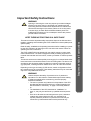
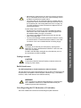
Power Availability
GXT2 10000T230
User Manual
10kVA
230V
50/60Hz
Table Of Contents
Important Safety Instructions ...................................................................... 1
1 Introduction and System Description ........................................................ 5
1.1 Device Overview..............................................................................................................6
2 Unpacking the UPS and Site Preparation ................................................. 7
2.1 Inspection .........................................................................................................................7
2.2 Required Setup Equipment...............................................................................................7
2.3 Unpacking ........................................................................................................................7
2.4 Storage..............................................................................................................................8
2.5 Handling ...........................................................................................................................8
2.6 Environmental Conditions................................................................................................8
2.7 Access required ................................................................................................................8
2.8 Floor/Rack Loading..........................................................................................................8
2.9 Inventory List ...................................................................................................................9
2.10 Clearance........................................................................................................................9
2.11 Repacking the UPS.........................................................................................................9
3 Installation.................................................................................................. 11
3.1 Electrical preparations....................................................................................................11
3.2 Installation Data .............................................................................................................12
3.3 Current Table and Suggested Cable Sizes......................................................................16
3.4 Neutral Connection ........................................................................................................17
3.5 External Protection and Isolating Devices .....................................................................17
3.6 Installation of Differential Protection Devices...............................................................18
3.7 External Electrical Connections .....................................................................................18
3.8 Connecting Mains and Load ..........................................................................................19
3.9 Terminal Blocks for UPS ...............................................................................................19
3.10 Connecting Power Cables ............................................................................................19
3.11 External Tower Batteries..............................................................................................20
3.12 Connecting an External Battery Extension ..................................................................20
3.13 Battery Precautions ......................................................................................................21
3.14 Configuration Program................................................................................................22
3.14.1 GXT2-10000T230 Configuration Program Features ......................................22
3.14.2 What You Will Need ......................................................................................22
4 Operation.................................................................................................... 23
4.1 Normal Operating...........................................................................................................23
4.1.1 Block diagram ...................................................................................................23
4.2 Control Panel..................................................................................................................24
4.2.1 Controls and Messages .....................................................................................24
4.2.2 Setup Parameter 53 of LCD Main Menu ..........................................................29
4.2.3 Warning Indicators ...........................................................................................29
4.2.4 Fault Indicators .................................................................................................29
4.3 Pre-startup ......................................................................................................................31
4.4 UPS Startup Procedure - Single Block...........................................................................32
4.5 UPS Shutdown Procedure - All Ratings ........................................................................33
4.6 Maintenance Bypass Procedure .....................................................................................33
4.7 Return from Maintenance Bypass Procedure.................................................................34
4.8 Maintenance Switch, Off position..................................................................................34
4.9 Functional Test...............................................................................................................35
4.10 Emergency Switch Device ...........................................................................................35
4.11 Remote Emergency Power Off ...................................................................................36
4.12 Self-Tests......................................................................................................................37
4.12.1 Lamp Test .......................................................................................................37
4.12.2 Battery Test .....................................................................................................37
5 Maintenance ............................................................................................... 39
5.1 Testing, replacement and disposal of batteries...............................................................39
5.1.1 Easy Battery Replacement ................................................................................39
5.2 Storage............................................................................................................................40
5.3 Cleaning .........................................................................................................................40
6 Interfaces .................................................................................................... 41
6.1 Communications Interface Port......................................................................................41
6.2 Relay Contacts................................................................................................................41
6.2.1 Pin 11 - Remote Shutdown on Battery .............................................................43
6.2.2 Pin 16 - Any Mode Shutdown ..........................................................................43
6.3 UPS Intelligent Communications...................................................................................44
7 Troubleshooting ......................................................................................... 45
8 Options........................................................................................................ 47
8.1 External Battery Cabinets...............................................................................................47
8.2 Additional Battery Charger ............................................................................................47
8.3 Optional Interfaces .........................................................................................................48
8.4 Battery Run Times .........................................................................................................48
9 Product Warranty Registration ............................................................... 49
Important Safety Instructions
WARNING
!
Opening or removing the cover may expose you to lethal voltages
within this unit even when it is apparently not operating and the
input wiring is disconnected from the electrical source. Observe all
cautions and warnings in this manual. Failure to do so may result
in serious injury or death. Refer all UPS and battery service to
qualified service personnel. Do not attempt to service this product
yourself. Never work alone.
This manual contains important safety instructions that must be followed when
installing, operating and maintaining the GXT2-10000T230 uninterruptible power
system (UPS).
Read all safety, installation and operating instructions before installing or operating the UPS. Adhere to all warnings on the unit and in this manual. Follow all
operating and user instructions.
The GXT2-10000T230 is not intended for use with life support or other designated critical devices. The UPS is designed for data processing equipment. If
uncertain the intended use for this UPS, consult your dealer or Liebert representative.
This device serves as an uninterruptible power supply for connected loads. Maximum load must not exceed that shown on the UPS rating label. The device is in
compliance with all relevant safety regulations concerning information technology equipment, including electronic machines for use in an office environment.
Depending on the type and rating of UPS device, certain configurations of battery extensions may be connected. These battery extensions may be connected
only to the compatible basic UPS unit...
WARNING
!
Liebert considers the safety of personnel to be of paramount
importance. For this reason it is essential that procedures relating
to safety be studied before commencing work and properly
adhered to thereafter.
• The user or operator may intervene in the operation of the UPS
provided that the instructions laid out in “Notes Regarding the
EU Declaration of Conformity” on page 3 are strictly adhered
to.
• The installation of the UPS, described in “Installation” on
page 11, may only be carried out by qualified technical personnel.
• Even when all switches and interrupters are open, hazardous
voltages are present within the UPS; any operation that
requires protective panels to be opened or removed may be
carried out by Liebert authorized technical personnel only.
1
Important Safety Instructions
KEEP THESE INSTRUCTIONS IN A SAFE PLACE
CAUTION
!
Important Safety Instructions
2
Carefully read the following safety notices! Failure to observe the
instructions may endanger your life, your health, the reliability of
your device and the security of your data.
• Transport the unit only in suitable packaging (protected against
jolts and shocks).
• If the equipment is moved from a cold environment to the operating room, condensation may occur. Before you switch on the
equipment, it must be absolutely dry. An acclimatization period
of at least two hours is required.
• The equipment must be installed in accordance with the environmental conditions specified in “Environmental Conditions”
on page 8 and in “Environmental Data” on page 12.
• The UPS should not be supplied with > IT (Impedance a Terre)
electrical power systems (IEC 364-ELECTRICAL
INSTALLATION OF BUILDINGS).
• Even with all switches in the “OFF” position(see “Control Panel”
on page 24) the UPS is not isolated from the mains. To isolate
completely from the mains, the power cables must be disconnected.
• In case of interruption of the mains voltage, the integrated battery maintains the power supply to the user equipment.
• Lay all cables so that nobody can stand on them or trip over
them. When connecting the UPS to the power supply, follow
the instructions in “Unpacking the UPS and Site Preparation”
on page 7.
• Make sure that no objects (e.g., pins, necklaces, paper clips,
etc.) get inside the device.
• In emergencies (e.g., damaged case, controls or power cables,
penetration of liquids or foreign matter), switch off the device
and contact the appropriate customer service representative.
• Do not connect equipment that will overload the UPS (e.g.,
laser printers or vacuum cleaners) or demand DC-current (e.g.,
half-wave rectifiers).
• When cleaning the unit, follow the instructions in “Maintenance”
on page 39.
• The sum of the leakage currents (protective conductor current)
of the UPS and the connected devices exceeds 3.5 mA for all
ratings of the UPS. Earth connection is essential before connecting supply.
• Data transmission lines should not be connected or disconnected during a thunderstorm.
• Remote Emergency Power Off (REPO) input is located on the
rear of the unit (see “Emergency Switch Device” on page 35
and “Terminal Blocks for UPS” on page 19). When this connection is open, the logic circuit will immediately shut down the
UPS output.
• An Emergency Switching Device (E.S.D.) must be fitted downstream of the UPS for the wiring installation safety to comply
with the European Harmonized Document HD384-4-46 S1.
!
• Maintenance bypass switch is for the use of service personnel
only. It is located under the rear cover. Open the safety cover to
operate the maintenance bypass switch.
• The Tower UPS may be connected either to 3-phase mains or
single-phase mains. Therefore the right input terminals have to
be connected (see “Connecting Mains and Load” on page 19).
The UPS autosensing mode ensures that it adapts to the connected mains supply.
Important Safety Instructions
Further safety notes for GXT2-10000T230
• Do not connect more than four GXT2-240TBATTCE battery
extensions to the GXT2-10000T230. This also applies when
the additional battery charger is connected.
• The vents for air intake and outlet at the front and rear side
must not be obstructed.
• The sum of the leakage currents (protective conductor current)
of the UPS and the connected devices exceeds 3.5 mA. Earth
connection of the unit is essential before connecting supply.
CAUTION
!
The supply to the load may be interrupted by opening all the
switches or by turning the Maintenance Switch on the rear of the
UPS to the Off position.
DO NOT USE WATER to extinguish any fires that may occur in
the area where the UPS is installed.
Leakage currents
CAUTION
!
Connect the protection earth (PE) safety conductor before connecting any other cables.
Radio Interference
The GXT2-10000T230 is a Radio Interference Class A Product.
The UPS device may cause radio interference. Do not place it near devices that
are particularly susceptible to electromagnetic interference (e.g., transmitters,
receivers, radar, metal detectors and antitheft devices).
WARNING
!
This is a product for restricted sales distribution to informed partners. Installation restrictions or additional measures may be
needed to prevent radio interference.
Notes Regarding the EU Declaration of Conformity
The GXT2-10000T230 conforms to the following European directives:
3
73/23/EEC
Directive of the council for adaptation of the legal regulations of the member
states regarding electrical equipment for use within specific voltage limits,
modified by directive 93/68/EEC.
89/336/EEC
Directive of the council for adaptation of the legal regulations of the member
states regarding electromagnetic compatibility, modified by directive 91/263/
EEC.
Conformity is established through compliance with the following standards:
EN 62040-1-1
EN 62040-2
Important Safety Instructions
Additional information regarding adherence to these directives is included in the
appendices NSR and EMC of the EU Declaration of Conformity.
If required, the EU Declaration of Conformity may be requested from Liebert.
4
1 Introduction and System Description
Congratulations on your purchase of the Liebert UPStation GXT2-10000T230.
This system provides conditioned power to microcomputers and other sensitive
electronic equipment.
The UPStation GXT2-10000T230 is a compact, on-line UPS. An on-line UPS
continuously conditions and regulates its output voltage whether utility power is
present or not. It supplies connected equipment with clean sinewave power.
Sensitive electronic equipment operates best from sinewave power.
For ease of use, the UPStation GXT2-10000T230 features an LCD display for
comprehensive user indications and programmable controls. It also provides
self-diagnostic tests.
The UPStation GXT2-10000T230 has an interface port for communication
between the UPS and a network server or other computer system. This port provides detailed operating information including voltages, currents and alarm status to the host system when used in conjunction with Liebert’s MultiLinkTM
software.
!
Figure 1-1
CAUTION
This UPS may only be operated by qualified personnel.
UPStation GXT2-10000T230 control panel
Liebert
UPStati o n GXT
ESC
BYPASS
FAULT
UPS ON
BATTERY
5
Introduction and System Description
Upon generation, AC power is clean and stable. However, during transmission
and distribution it is subject to voltage sags, spikes and complete power failure
that may interrupt computer operations, cause data loss and damage equipment. The UPStation GXT2-10000T230 protects equipment from these disturbances.
1.1 Device Overview
The GXT2-10000T230 is available at various nominal power ratings.
The following table provides an overview of the various versions of the device:
Table 1-1
Overview of UPS devices and batteries
Type
UPS with integrated battery
Battery cabinet
Figure 1-2
Model #
GXT2-10000T230
GXT2-240TBATTCE
GXT2-10000T230 front and rear views
Introduction and System Description
1.Control panel
2.Liquid Crystal Display
3.Ventilation Louvers
4.Control keys
Liebert
UPSta ti on GXT
1
2
Liebert
UPSt at i on GXT
ESC
4
Nominal power
10000 VA / 7000 W
240 VDC
BYPASS
FAULT
UPS ON
BATTERY
3
5 6 7
5. Intellislot port (covered)
6. REPO contacts
7. Communications port 1
8. Parallel port (Reserved for future use)
9. Maintenance Bypass Switch (behind cover)
10.Bypass source input circuit breaker
11.Input breaker for three phase source
12.Removable sheet panel (2nd charger board
can be inserted here)
13.Hardwire input and output connector terminal
block
14.External battery connector
15.Cooling fans
16.Relay Contacts
6 Device Overview
8
16
15
ON
ON
OFF
OFF
ON
OFF
ON
OFF
OFF
M3
OFF
OFF
60A
OFF
30A
30A
9
10
11
0
Bypass Source
Input Breaker
Input Breaker for
Three Phase Source
60A/250V
60A/30A/30A/250V
OPTIONAL
EXT BATTERY
240V
40A
14
13
Main 1 Input~
L1
L2
L3
Main 2 Input~
N
N
Ouput~
L
N
S
12
2 Unpacking the UPS and Site Preparation
2.1 Inspection
2.2 Required Setup Equipment
The following tools are required to set up your UPS:
• pallet jack
• utility knife or scissors
• star head screwdriver
2.3 Unpacking
Take care when removing the packaging to avoid damaging the UPS. Check all
packaging to ensure that no items are accidentally discarded. Remove the packaging in the sequence shown below.
Figure 2-1
Unpacking
Inspection 7
Unpacking the UPS and Site Preparation
Upon receiving your GXT2-10000T230, examine the packaging for any signs of
mishandling or damage. While removing the packaging materials, inspect the
UPS for damage. If any damage is noted, notify your local Liebert representative
and carrier. Any damage or missing parts must be reported to the supplier within
eight days of delivery.
2.4 Storage
If the UPS will not be installed immediately, store the unit indoors in a clean and
dry area. Protect all the equipment, including its batteries, from extreme temperature, high humidity, spills and other damaging conditions. Refer to the table
below for permissible storage environmental conditions.
Table 2-1 Storage conditions
Unpacking the UPS and Site Preparation
Temperature limits
Batteries ONLY
0oC to +40oC
(32-104oF)
Temperature limits
UPS without batteries
-25oC to +55oC
(-13oF to +131oF)
from 0% to 90%, NONCONDENSING
Relative humidity
2.5 Handling
The equipment must be kept upright at all times and handled with care. It may be
damaged if dropped or subjected to severe impact.
2.6 Environmental Conditions
The GXT2-10000T230 must be installed vertically, on a level and even surface
and in an area protected from extreme temperatures, water, humidity and the
presence of conductive powder or dust (see “Environmental Data” on page 12).
Do not stack units; do not place any objects on top of a unit.
• The functional temperature range of the UPS is 0oC to 40oC (32-104oF)
• The ideal ambient temperature range is 15oC to 25oC (59-77oF)
• The battery life is defined at 20oC. Each increment of 10oC above 25oC
(increment of 18oF above 77oF) reduces the expected life by 50%.
2.7 Access required
The area must have sufficient space for installation procedures and for routine
maintenance. Access doors must be sufficiently large to permit passage of the
UPS.
2.8 Floor/Rack Loading
Ensure that the floor where the UPS/batteries will be installed will support the
unit’s weight (see Table 3-2 for the unit’s weight).
8 Storage
2.9 Inventory List
2.10 Clearance
The UPS is fitted with wheels for ease of movement over short distances. You
must leave 300 centimeters around the side and rear of the unit to allow a flow of
air and to provide access for any routine maintenance that may involve removal
of the panels.
Figure 2-2
Clearance
2.11 Repacking the UPS
To repack the UPS, proceed as follows:
1. Do not pack the equipment until at least six hours have elapsed since the last
recharge.
2. Make sure to re-use the original packing material to ship the UPS.
Inventory List 9
Unpacking the UPS and Site Preparation
• The GXT2-10000T230 comes with the following:
- one jumper for common feeding (connect mains and reserve)
- user manual
- multi-link CD
- Configuration program CD
- RS232 cable
- Four rubber bumpers to be used if adding a GXT2-240TVBATT next to
the UPS.
3 Installation
3.1 Electrical preparations
Before you begin installation, the input source must be isolated and secured to
prevent reconnection during installation. The input circuit breaker on the rear of
the UPS must be in the Off position.
Warning
!
• Installation may be carried out only by qualified technicians,
conforming to applicable safety standards.
• Electric shock hazard: Even when the unit is disconnected from
the mains, hazadous voltage may still be supplied by the battery. Both poles should be disconnected before carrying out
maintenance work inside the UPS.
Installation
For electrical installation, the nominal current rating of the source must be
observed. The UPS is not suitable for connection to 16A subdistribution systems.
Electrical preparations 11
3.2 Installation Data
Table 3-1
Environmental Data
0oC to +40oC
(32-104oF)
Ambient Temperature
Relative Humidity
(w/o Condensing at 20oC)
Max. Altitude
(w/o derating)
Cable inlet
Air inlet
Air outlet
Table 3-2
90%
1000 m a.s.l.
bottom of rear side
at the front and right sides
at the rear
Technical Data
Specification
Value
Rectifier
GXT2-10000T230
230VAC Single Phase (L, N, G)
Nominal input voltage (VAC)
Installation
230/400 Three Phase (L1, L2, L3, N, G)
Single phase or three phase,
automatic detection
176-276V for 1X1
Input phases (VAC)
Input voltage
304-478V for 3X1
50/60 Auto selection
Output frequency equals input frequency. When the input is nominal 50 or
60Hz ± 5%. Beyond ± 5% range, inverter
free runs at nominal frequency.
Nominal frequency (Hz)
Frequency tolerance
Maximum input power (Nominal Input Voltage, R Full Load)
Float(kVA)1
8.0
Recharge (kVA)2
Power factor (at nominal V, with R
full load)
Input current distortion (with R full
load) THDi3
8.3
Inrush current (A) (typical)
60A
Single Phase Input: 0.97
Three Phase Input: 0.95
Single Phase Input: < 5%
Three Phase Input: < 31%
Battery charger
Battery nominal voltage (V DC)
240
Battery charger input voltage range
100-276
(V AC)
Output voltage (V)
Multi stage charging method.
12 Installation Data
Table 3-2
Technical Data
Charging time to 90% capacity in
inverter mode (hr.)
5
Charger output current (ADCaver)
(Amps)
Standard: 1.2A (1 Charger Board with
Internal Batteries)
Option: 4.0A (internal option)
Inverter
Load peak factor without derating
(lpk/lrms)
10
7
0.7
105 - 125%
126 - 150%
150 - 300 (± 50)%
160 A peak
Installation
Nominal power rating @ 40°C
(kVA)
Nominal active power rating (kW)
Power factor
Overload
• for 1 minute (%)
• for 10 seconds (%)
• for approximately 2 secs (RCD
load) then transfer to bypass
and and an audible alarm
Short circuit current for 5 cycles
(typical)
Output voltage rating (Vac)
Output frequency (Hz)
Voltage regulation over input voltage and battery voltage range with
load between 0% and 100% of rating
Output frequency stability with
mains synchronism (%)
Stability with internal quartz oscillator (%)
Frequency Variation Rate (Hz/sec)
Output Voltage Distortion THD-V
(%)
220, 230, 240
50/60, auto selection
± 2%
± 5%
< 0.05%
<1
Full Resistive Load < 3%
Full RCD Load < 8%
≤3
Static switch
Nominal frequency (Hz)
Frequency tolerance (%)
Voltage tolerance (V)
Out-of-phase switching time (ms) in
case of inverter fault and bypass is
out if tolerance
50 / 60 auto selection
Same as Input, ± 5%
176 - 255
No transfer
Overload
Over load > 100%
Audible alarm
Installation Data 13
Table 3-2
Technical Data
In-phase switching time - direct/
conditioned (ms)4
Installation
condition/direct (ms)
UPS data
25% of load (%)
50% of load (%)
75% of load (%)
100% of load (%)
Maximum noise level at 1 meter
front-side (dBA) normal mode and
battery mode
Degree of protection
Dimensions
Height (mm)
Width (mm)
Depth (mm)
Color
Weight with integrated batteries
(kg)
0.5
0.5
87
91
92
92
≤ 50
IP20
800
300
675
Black
110
Battery
Optimum battery temperature (°C)5
Power output (kW)
Recommended no. of cells
End of discharge (VDC)
Battery type
Battery number
Discharging time (minutes)
Auto battery missing detection
Ext. Battery Cabinet:
Battery type
Battery number (pcs.)
Height (mm)
Width (mm)
Depth (mm)
Color
Weight with integrated batteries
(kg)
14 Installation Data
15 - 25
8.5
120
200
YUASA:
REW 45-12
(12V / 45W / 9Ah)
20
5
Yes
1Set / 2Set
YUASA NP7-12 12V7AH
40 / 80
800
300
675
Black
162
Table 3-2
Technical Data
Performance EN 62040-3
Dynamic characteristics
Step load response
Load 0% to 100% to 0%
Load 20% to 100% to 20%
VFI - S S - 1 1 1
+/- 5% maximum, returns to static regulation within 200 ms.
+/- 3% maximum, returns to static regulation within 200 ms.
Startup Operation
1
Maximum input power (normal V, R full load)
float (kVA) = [Pout (KW)/efficiency] / input_power_factor
Example for the 10kVA float (kVA) = (7,0/0,91)/0,95 = 8100VA
2
Recharge (kVA) = [(Pout (KW)/efficiency)+Pbattchargerinput]/input_power_factor
Example for the 10kVA Pbattchargerinput = (2.5*268)/efficiency=(2.5*268)/0,9=744W
recharge (kVA) = [(7,0 (KW)/0,91)+744]/0,95 = 8880VA
3 THDi measure method is applied to EN61000-3-2, 1995
4 In-phase switching time direct / conditioned means time line (bypass) transferring to inverter
5
The expected battery life is defined at 20°C. For every increment of 10°C, above 20°C, the expected
life is halved
Installation Data 15
Installation
Input AC < 100VAC or greater than
UPS will not start
280 VAC
Input >176 or less than 276
UPS start enabled
+/- 5% maximum, returns to static reguLoad 0% to 100% to 0%
lation within 200 ms.
3.3 Current Table and Suggested Cable Sizes
The following table indicates the currents and recommended sizes of the connecting cables in accordance with regulations IEC-287 and DIN VDE 0298
1. PVC-insulated copper cables (@ 70oC) (158oF).
2. Air temperature surrounding the conduits should not be greater than 30oC
(86oF).
NOTE
Should there be any variation in the conditions, it will be necessary to
verify whether the cable dimensions satisfy the requirements of IEC287 and DIN VDE 0298. In cases where the cables are so long that
they cause a drop in voltage of >3%, a larger size must be used.
Table 3-3
Connection data
Description
Installation
Connector size
Max input current
Input cable size
(and neutral)
Max output current
Output cable size
(and neutral)
Earth cable size
Unit
UPS power rating
kVA
10 - 1/1
10 - 3/1
mm2
Arms
10
10
56
56
mm2
10
10
Arms
56
56
mm2
10
10
mm2
10
10
When the UPS is in Bypass mode, the entire output current of the UPS is passed
through the phase L1 and Neutral cables. To simplify connection data, no distinction has been made between phase L1 and phases L2 and L3. The cable
sizes are defined for the maximum current carried by the output cables.
WARNING
!
Particularly sensitive equipment may be susceptible to interference. To prevent this, Liebert suggests:
• Mains input, output and external battery cables to the UPS in
earthed, metal conduits, or
• Use shielded cables
Routing of cables (e.g. power supplies, communication or data
lines) to other equipment, should be kept separate from that of
UPS cables.
16 Current Table and Suggested Cable Sizes
3.4 Neutral Connection
The installation of the UPS does not affect the existing Neutral system.
The Neutral system may be affected if the UPS is operating with the Neutral
switched upstream.
3.5 External Protection and Isolating Devices
External devices for the protection of cables and for isolating the UPS external to
the UPS must be installed upstream of the equipment. Select and configure the
isolating device according to the table below.
• Such devices must be either curve C automatic circuit breakers or type GL/
GG fuses.
• Disconnecting devices must be provided in building installations and other
locations.
WARNING
The following label must be displayed on all switching devices
installed in the same electrical system as the UPS, even when
they are located at a distance from the area.
ENSURE THAT THE UNINTERRUPTIBLE POWER SYSTEM IS
ISOLATED BEFORE WORKING ON THIS CIRCUIT.
Table 3-4
Input
Fuse
Breaker
Tower power rating (phases in/out)
10 - (1/1)
10 - (3/1)
63 Amps
63 Amps
63 Amps
63 Amps
Output
Fuse
Breaker
63 Amps
63 Amps
Protection
Description
63 Amps
63 Amps
This table indicates the protection devices (circuit breakers and fuses) that must
be installed for the protection of both the cables and the equipment.
NOTE
If an external battery cabinet is present it should be located next
to the UPS unit.
• When such an option is supplied by Liebert it comes complete
with protection devices and correctly-sized cables.
• When batteries are sourced from other suppliers, you should
contact Customer Support Technical Service for correct sizing
of protection devices and interconnection cables.
Neutral Connection 17
Installation
!
3.6 Installation of Differential Protection Devices
To avoid spurious operation, differential protection devices must be:
• rated at differential current NOT LESS THAN 100mA
• a SELECTIVE type (delayed intervention)
• Type A
'
LOAD
Figure 3-3
Standard configuration -- differential breaker
3.7 External Electrical Connections
Installation
Remove the protective panel on the rear of the UPS to access the external electrical connections (see figure below). Once the cables have been connected they
must be passed through the cable clamps that will hold them in position. Connect the earth cable first.
!
WARNING
Ensure that the UPS is isolated before removing panels.
Figure 3-4
Side view
NOTE
Once installation has been completed, fix the UPS in position by
screwing the stabalizing plates underneath the unit firmly to the
floor.
18 Installation of Differential Protection Devices
3.8 Connecting Mains and Load
Connect the mains supply to the input terminals of the UPS. If the GXT210000T230 is supplied by single-phase mains, connect the live phase to input
L1.
3.9 Terminal Blocks for UPS
The three-position maintenance switch includes the output breaker.
L1
L1
L2
L3
Main 2 Input~
N
Figure 3-5
L
N
Ouput~
L
N
Parallel
Connection
S1
S2
Parallel Connection
(Reserved for future use)
Hardwire terminals
3.10 Connecting Power Cables
1.
2.
3.
4.
5.
6.
Open the UPS input breaker.
Open the UPS output breaker.
Set the maintenance switch to position BPS (Bypass).
Remove the terminal area safety cover from the rear UPS panel.
Connect loads to the output terminals.
Connect the mains to the corresponding input terminals (see Figure 3-5).
• If the reserve input is to be supplied separately, connect reserve line to the
Mains 2 terminals.
• If the UPS is supplied by a common mains, connect a jumper between terminal L1 (mains 1) and L (reserve/Mains 2).
Connecting Mains and Load 19
Installation
Main 1 Input~
3.11 External Tower Batteries
One or more battery cabinets may be connected to the GXT2-10000T230. A
cable to connect the battery cabinet and the GXT2-10000T230 is supplied with
each battery cabinet. Plug this cable into the battery cabinet and UPS battery
sockets -- slotted fittings on each and ensure that the connection is properly
made. If your UPS has an integrated battery, a compensating current may occur
during connection.
BATTER Y C ONNECTOR
240V
40A
BATTER Y C ONNECTOR
240V
40A
ON
ON
OFF
OFF
ON
OFF
ON
OFF
OFF
M3
OFF
OFF
60A
OFF
30A
30A
0
Bypass Source
Input Breaker
Input Breaker for
Three Phase Source
60A/250V
60A/30A/30A/250V
OPTIONAL
EXT BATTERY
240V
40A
Main 1 Input~
L1
Installation
Figure 3-6
L2
L3
Main 2 Input~
N
N
Ouput~
L
N
S
GXT2 10000T230 with External Battery Cabinet
3.12 Connecting an External Battery Extension
NOTE
External battery extensions can be replaced during normal operation of the UPS (hotswappable). However, the batteries must NOT
be changed when the UPS is in the status “Battery Mode operation”.
The unit checks the battery voltage (a beep is heard) once more and stays in
bypass till a constant battery voltage is present.
CAUTION
!
Battery maintenance must be carried out by authorized personnel
observing the necessary precautions.
20 External Tower Batteries
• The batteries installed in the UPS and within the battery extensions may
contain electrolyte. Under normal conditions, the containers are dry. A
damaged may leak electrolyte which can cause skin and eye irritation.
Should this happen, wash the affected area with plenty of water and seem
immediate medical attention.
• Do not open or damage batteries. The released electrolyte is toxic.
• Voltage is always present on the battery contacts.
• Even when discharged, a battery has the capacity a high short circuit current which, in addition to causing damage to the battery itself and associated cables, may expose the operator to the risk of burns. The following
precautions should be observed when working with batteries:
• Remove watches, rings and other metal objects.
• Use tools with insulated handles.
• The voltage of a single cell of a battery is not dangerous. However a number of cells or battery blocks, connected in series, can produce hazardous
voltages.
• The battery cabinet must not be kept in storage or not used for periods
exceeding six months (at 20°C) without being recharged (having been
charged to 100% at the beginning of any such period). If this period is
exceeded, it is essential that the batteries be recharged (which requires the
UPS to be switched on). If these conditions are not met, the battery performance can no longer be guaranteed. We recommend recharging the batteries at least once every four months.
• Since new batteries often do not provide full capacity after the initial
charge, it may be necessary ti carry out a number of discharge/recharge
cycles before optimum performance is reached.
• When replacing batteries, replace with the same type and number of batteries and battery packs.
• In order to protect the environment, batteries must be disposed of in accordance with local laws concerning the safe disposal of toxic and harmful
waste.
• Do no not dispose of batteries in a fire. The batteries may explode.
Battery Precautions 21
Installation
3.13 Battery Precautions
3.14 Configuration Program
The final step of installation may require custom configuration of your UPS using
the enclosed configuration program. Some configuration settings may be
changed only while the UPS is off. These should be set before the UPS is put
into full-time use.
For most users operating with 230VAC, the factory default settings will be adequate.
3.14.1 GXT2-10000T230 Configuration Program Features
• Select one of the three L-N output voltages to match local voltage.
• Enable/disable auto-restart.
• Select frequency converter operation with a fixed output frequency of 50 or
60 Hz.
• Set the ‘Low battery warning’ alarm time from 2 to 30 minutes.
• Enable/disable auto-battery test.
• Set auto-battery test frequency to 7, 14, 21 or 28 days.
• Specify the number of external battery cabinets connected to the UPS to
adjust the remaining run time calculations reported by the system software.
Installation
3.14.2 What You Will Need
In addition to the GXT2-10000T230, you will need the configuration program CD
and serial cable (beige or tan, 3-wire: GND, TX, RX; straight through 2-2, 3-3,
5-5) included in the UPS accessory pack. You must be running Windows 95® or
later on your computer.
22 Configuration Program
4 Operation
4.1 Normal Operating
4.1.1 Block diagram
The GXT2-10000T230 consists of several main components:
• 2 mains supplies (mains and reserve)
• Rectifier/booster, inverter and charger
• Electronic bypass
• 2 input breakers
• 3 position maintenance bypass switches
• TVSS filter
• Integrated battery (expandable)
• Additional charger (optional)
Electronic Bypass
N
L
N
Re c t i f i e r /
Booster
S2
S1
N
L1
L2
L3
L
L 2 ,L3: a t 1 0 k VA
device only
Inverter
N
M aintenance
swi tch
(OFF)
(UPS)
(BYPASS)
Maintenance
switch
TVSS
Backfeed
Protection
logic
Additional
Charger
Ext. Battery
Figure 4-1
10kVA TOWER
Overview of UPS tower
Normal Operating 23
Operation
L
Load
Ma i n s 1
Ma i n s 2 ( R e s e r v e )
Maintenance Bypass
4.2 Control Panel
The display text is shown as a 10 kVA UPS.
Liebert
UPStation GXT
1
2
8
ESC
3
BYPASS
7
6
FAULT
UPS ON
4
5
BATTERY
Figure 4-2 Control Panel
1.LCD
2.Enter key
3.Menu Up / Down keys
4.Fault LED
5.Battery LED
6.UPS On LED
7.Bypass LED
8.Escape key
4.2.1 Controls and Messages
Lighted LEDs
Operation
LED Indicator
LED Color
Description
UPS ON
Green
UPS is online and operating normally
BYPASS
Amber
Load is supplied by the mains via automatic
bypass
BATTERY
Amber
Load is supplied by the battery
FAULT
Red
An error has occurred within the UPS
Flashing LED:
When the BYPASS LED is flashing, the mains is out of tolerance
!
CAUTION
Do not switch off the UPS or switch from online to
bypass whilst in this status, otherwise load will no
longer be supported.
The following displays the menu structure that can be accessed through the control panel. Press the Menu Up or Menu Down buttons to scroll through each
menu. Press Enter to choose an entry.
24 Control Panel
Menu entry
0. START
WINDOW
Menu entry
1. SYSTEM
STATUS
Operation
Figure 4-3
System block, menu structure
Display
10kVA UPS
Self testing please wait
Wait about 6 sec
Display
10kVA UPS
UPS: “UPS mode/Warning table/Fault table” menu
All UPS mode/Warning table of Fault table will alternate once a second
Control Panel 25
Menu entry
Display
Control
Status
2. MAIN MENU
Setup
Logging
About
Menu entry
Display
Turn UPS to ONLINE
31
Turn UPS ON/OFF
Turn UPS to BYPASS
Turn UPS to shutdown
Turn UPS to no output
Operation
3. CONTROL
MENU
32
Reset fault
33
Buzzer control
34
26 Control Panel
Manual batt test
Reset fault
No fault now
Alarm ON
Alarm OFF
341
10 Seconds test
342
X Minutes test
343
Test till batt low
344
Cancel batt test
345
Test report
4. STATUS
MENU
Display
Measure value
Unit
L1 Input Voltage
V
L2 Input Voltage (only
10kVA UPS)
V
L3 Input Voltage (only
10kVA UPS)
V
Input Freq
0.1Hz
Output Volt
V
Output Freq
0.1Hz
Output Load
%
Output current
A
Output Watt
W
Output VA
VA
Battery Volt
V
Batt capacity
%
Back Up
Min, sec
RunTime
day:hr:min:sec
Operation
Menu
UPS ID
Plus BUS (Booster)
V
Minus BUS (Booster)
V
Control Panel 27
Menu
Display
Setting (level 1)
Setting item
5. SETUP
MENU
Setting (level 2)
51
Buzzer
alarm
Disable/Enable
52
Output
voltage
220/230/240 V
53
Battery
pack
1-31
54
Battery
test
541
Batt Test
Time
1-99 min
542
Batt Test
Period
7-180 day
543
Manual/
Auto test
Manual/Auto
Operation
55
DC start
Disable/Enable
56
UPS
address
0-31
57
Series no. 00000-99999
58
Language English
Display
6. LOGIN
MENU
61
Event and time2
62
Clear event log
Display
Type of UPS
7. ABOUT..
Internet IP
MENU
Software version
1
For more information about setup parameter 53 or battery packs see “Setup
Parameter 53 of LCD Main Menu” on page 29.
2
A maximum of four fault event records will be stored.
28 Control Panel
4.2.2 Setup Parameter 53 of LCD Main Menu
Paramter
Integral battery
No. of external
battery cabinets
No. of 12V battery blocks
in sum
1
YES
0
20
2
YES
1
60
3
YES
2
100
4.2.3 Warning Indicators
If a warning indicator appears, the UPS continues to operate. The warning message alternates with UPS mode once a second.
Warning
Cause
Corrective Steps
1
Batt. under volt.
N/A
2
Utility failure
N/A
3
L2 or L# failure
Check L2, L3 input fuse
4
Over temp. 65
Reduce load
4.2.4 Fault Indicators
If a fault occurs, the UPS automatically switches to BYPASS mode. Only in the
case of a battery disconnection fault will the original operating mode be maintained. The fault message alternates with UPS mode once a second, the red
fault LED lights up on the control panel and the buzzer sounds continuously. If a
fault occurs oriceed as follows:
Buzzer alarm operation - The buzzer alarm can be switched on or off.
Clear Fault - Present fault condition can be reset if fault condition is cleared,
either automatically or by the user.
Fault information - A maximum of 4 faults can be displayed in this window. All
fault displays include:
• The nature of the event
• The time of the event
Control Panel 29
Operation
The warning indicators are described below:
Display faults - The fault indicators are as follows:
Fault
Cause
Corrective Steps
Operation
1
DC BUS fault
Call customer service
2
Inverter fault
Call customer service
3
Over heating
Reduce load
4
Batt. over volt.
Call customer service
5
Batt. mode overload
Reduce load
6
Output overload
Reduce load
7
Output short
Call customer service
8
Fan lock fault
Call customer service
9
Batt. disconnect
Check battery connector
10
Charger failure
Call customer service
11
ESD activated
N/A
12
Parallel fault
Call customer service
13
Internal fault
Call customer service
14
Output failure
Call customer service
30 Control Panel
4.3 Pre-startup
Before switching on the UPS and supplying the load, ensure the following:
• The ventilation grilles are unobstructed
• The earth connection is in place
• The ‘consumer’ breakers are in the OFF (0) position
• The UPS rear panel breakers are in the OFF (0) position
!
WARNING
As soon as the UPS is connected to input power, the
output sockets are live, even if the UPS is not yet
switched on.
Once recharging has been completed, the UPS is ready for use.
NOTE
You may experience problems with the electrical supply if you do
not If follow these instructions.
Pre-startup 31
Operation
!
WARNING
Do not connect any devices that may overload the
UPS or draw DC current.
4.4 UPS Startup Procedure - Single Block
1. Ensure all switches and circuit breakers upstream of the UPS are closed.
2. Ensure mains connections are secured at the UPS input. UPS requires twin
supplies or one supply and one bridge. If the UPS is supplied from one mains
only, mains connectors have to be fixed to the terminals section Mains 1. The
jumper must be fixed as follows:
From L1 - mains 1 to L - mains 2
Operation
3. Switch both Input breakers (mains 1 and mains 2/reserve) to ON (I). The LCD
displays ‘Self testing, please wait’ (see “Controls and Messages” on
page 24).
4. Wait at least 30 seconds until the output voltage has stabilized (the yellow
LED is lit). The LCD displays ‘BYPASS MODE’. Then turn the Maintenance
Switch to UPS.
5. Check setup menu 5, check and adjust if necessary parameters for language,
voltage and battery pack(s) (see ‘“System block, menu structure” on page 25’
for more information). The default language is English.
6. Close any external switches connecting the load (if present).
7. Press the Menu button, select Control and press OK.
8. Select Turn UPS ON/OFF and press OK. The LCD will display ‘Turn UPS to
ONLINE’.
9. Press OK to switch on the inverter.
!
WARNING
If the load indication is greater than 100%, then the
energy demand from the connected load exceeds
the power rating of the UPS. In addition to the a
warning on the front panel, a beep (once a second)
will sound.
32 UPS Startup Procedure - Single Block
4.5 UPS Shutdown Procedure - All Ratings
NOTE
Carrying out this procedure will interrupt the supply to load.
1. Press the Menu button, select Control and press OK.
2. Select Turn UPS ON/OFF and press OK.
The LCD displays ‘Turn UPS to Bypass’.
3. Press OK to switch off the inverter.
4. Open any external switches connecting the load (if present).
5. Switch both input switches to the Off Position.
6. Ensure all switches and circuit breakers upstream of the UPS are open.
7. Ensure that all LEDs on the control panel are not lit.
The UPS is now shut down.
1. Press the Menu button, select Control and press OK.
2. Select Turn UPS ON/OFF and press OK.
The LCD displays ‘Turn UPS to BYPASS’.
3. Press OK to switch off the inverter.
4. Remove the safety cover from the Maintenance switch and switch the UPS to
BYPASS.
NOTE
At this point the load is no longer protected against interruptions
and disturbances of the mains supply.
5. Switch output and input switches to the Off position.
6. The UPS is now switched off, all LEDs are off and the load is supplied directly
from the mains.
UPS Shutdown Procedure - All Ratings 33
Operation
4.6 Maintenance Bypass Procedure
4.7 Return from Maintenance Bypass Procedure
1. Ensure all switches and circuit breakers upstream of the UPS are closed.
2. Switch both input switches to the On position.
3. Wait at least 30 seconds until the output voltage has stabilized (the yellow
LED is lit).
4. Switch the Maintenance switch from BYPASS to UPS and replace the cover.
The load is now supplied via electronic bypass.
5. Press the Menu button, select Control and press OK.
6. Select Turn UPS ON/OFF and press OK.
The LCD displays ‘Turn UPS to ONLINE’.
7. Press OK to switch on the inverter.
4.8 Maintenance Switch, Off position
Switch the maintenance switch to the Off position to disconnect the UPS output
from output distribution.
!
WARNING
Connected loads are not supplied if the Maintenance
Switch is set to the Off position.
Operation
34 Return from Maintenance Bypass Procedure
4.9 Functional Test
NOTE
Supply to the load is not guaranteed during this test. The test
should not be carried out if a critical load is connected to the UPS.
The GXT2-10000T230’s controls permit testing the UPS to ensure that the load
will be supplied in the event of a mains failure.
Before beginning, ensure that the batteries are fully charged.
Simulate a mains failure by interrupting the mains supply to the UPS. You can do
this by switching off the input power circuit breaker on the rear panel of the UPS.
If the mains supply to the GXT2-10000T230 is protected by an external circuit
breaker, that circuit breaker may be opened to interrupt the mains supply and
simulate a power failure.
When the interval between the audible signals decreases to one second, the
UPS has battery reserve energy to supply the load for a maximum of two more
minutes. After two minutes, the GXT2-10000T230 will automatically shut down.
If the batteries do not supply the load during the simulation, refer to “Troubleshooting” on page 45. To end the simulated mains failure, restore the input
power supply to the UPS. The UPS is now ready for operation.
NOTE
The batteries must be recharged before the complete emergency
supply period is again available.
4.10 Emergency Switch Device
For safety reasons, an Emergency Power Off switch must be installed to shut
down the UPS immediately. To do so, follow these steps:
1. Remove the connections between the ESD terminals on the rear of the UPS.
2. Connect an emergency switch (that will be closed under normal operating
conditions and held open mechanically when activated).
Once the emergency situation causing the switch to open has been resolved,
open all UPS switches (Input, Output and Battery) and restart the GXT210000T230 as described in “UPS Startup Procedure - Single Block” on page 32.
Functional Test 35
Operation
The GXT2-10000T230 is operating properly and the batteries are charged if:
• An audible signal is heard at four-second intervals
• The UPSOn LED indicator turns off
4.11 Remote Emergency Power Off
The UPS is equipped with an Emergency Power Off circuit. A factory-installed
jumper allows the UPS to operate without an external shut-off switch.
If a Remote Emergency Power Off switch is required, a switch with normally
closed contacts must be used.
Connect the switch contacts to the UPS by removing the factory-installed jumper
as shown.
Operation
36 Remote Emergency Power Off
4.12 Self-Tests
4.12.1 Lamp Test
NOTE
This test involves putting the GXT2-10000T230 into bypass mode.
The load is not protected against any mains disturbance or interruptions while the UPS is in bypass mode.
1. With the GXT2-10000T230 connected to the mains, press the Menu button,
select Control and press OK.
Select Turn UPS ON/OFF and press OK.
The LCD will show ‘Turn UPS to BYPASS’.
2. Press OK to switch the inverter to Bypass mode.
A system confirmation beep will sound.
4.12.2 Battery Test
During the test a beep will sound as though the device is operating in battery mode.
1. Press the Menu button.
2. Select SETUP and press OK.
3. Select BATT TEST and press OK.
A system confirmation beep will sound and the load will be supplied by the
battery.
If the test is successful, the BATT LED will stop flashing and the UPS will return
to Line mode. If the UPS circuitry detects a battery malfunction, the system will
display an alarm (see “Controls and Messages” on page 24)
See below for battery test report messages:.
Menu entry
Display
NoTest InProgress
Test in progress
Test OK!
Battery test
report
Test fail
Test inhibit
Test stop by user
Test autonomy
Test unknown
Self-Tests 37
Operation
NOTE
5 Maintenance
5.1 Testing, replacement and disposal of batteries
The UPS does not require maintenance by the user. When the batteries expire,
they must be replaced by the appropriate customer service representative. For
servicing, replace batteries with the same type and number of batteries or battery packs that were installed at the factory. For the battery type, see “Technical
Data” on page 12.
Disposal of the UPS and batteries should be carried out by a certified disposal
company - observe all local regulations and laws. Exhausted accumulator batteries are classified as harmful toxic waste and as such the law demands that they
be disposed of by an authorized recycling centre.
The Liebert power protection customer service centre is fully equipped to deal
with such batteries, in accordance with the law and with the greatest respect for
the environment.
The battery test(see “Battery Test” on page 37) should be run periodically (every
six to twelve months) to ascertain the general condition of the batteries and to
ensure maximum run time.
5.1.1 Easy Battery Replacement
Open the front panel as shown below. Ensure that a certified service engineer is
present to replace the batteries.
1. Open the battery tray DC connectors as shown
2. Remove the battery trays from the cabinet
3. Replace the old batteries with a new set. Replacement batteries must be the
same type installed at the factory
4. Reconnect the battery cables
Figure 5-1
Removing front panel and unlocking battery trays
Testing, replacement and disposal of batteries 39
Maintenance
The typical battery life cycle is three to five years, at an ambient temperature of
25°C, but is also dependent on the frequency and duration of mains failures.
DC connectors
Maintenance
Figure 5-2
Disconnecting battery tray and battery packs
5.2 Storage
For extended storage at ambient temperatures cooler that 25°C (77°F), the batteries should be charged for five hours once every four months. At higher storage temperatures. Liebert recommends charging batteries for five hours every
two months.
After five hours, disconnect from the mains supply or switch off the input miniature circuit breaker of the UPS. Then remove the UPS connections in the opposite sequence to that described in “Installation” on page 11.
Record the battery charging date in the vicinity of the UPS, for example. on its
packaging.
5.3 Cleaning
1. Do not clean the UPS with scouring powder or solutions that may dissolve
plastic.
2. Do not allow liquid to get inside the UPS.
3. Make sure that the air vents on the UPS are not obstructed. Remove dust
from the air vents with a vacuum cleaner.
4. Clean the outside of the UPS by wiping the housing with a dry or slightly damp
cloth.
40 Storage
6 Interfaces
6.1 Communications Interface Port
The GXT2-10000T230 has a standard DB-9 serial port female connector located
on the rear of the unit. Several signals are provided on this port and are assigned
as follows:
DB-9 Pin
Assignment Description
2
UPS TxD (typically RS-232 levels)
3
UPS RxD (typically RS-(232 levels)
5
Common
Pin Assignment
6
1
7
2
8
3
9
4
5
10
20
9
19
8
18
7
17
6
16
5
15
4
14
3
13
2
12
1
11
Relay Contacts Pin Information
Pin
Function
Operation
1
UPS Fault
Closed if no UPS failiure
2
UPS Fault
Closed if UPS fails
3
Summary Alarm1
Closed if SUMMARY ALARM occurs
Communications Interface Port 41
Interfaces
6.2 Relay Contacts
Relay Contacts Pin Information
Pin
Function
Operation
4
Summary Alarm1
Closed if no alarm conditions occur
5
Signal Ground (for UPS Any
Mode Shutdown)
6
Common - Low Battery
7
Low battery
Closed if battery is OK
8
Low Battery
Closed if LOW BATTERY warning
occurs
9
JP01
Allows all 3 common relays to be tied
together
10
Interfaces
11
UPS Battery Mode Shutdown Active when connected to pin 5
12
On UPS
Closed if UPS power in on (inverter).
13
On Battery
Closed if battery power is on (utility failiure)
14
Common - UPS Fault, Summary Alarm, On UPS, On Battery, On Bypass
15
Common - UPS Fault, Summary Alarm, On UPS, On Battery, On Bypass
16
UPS Any Mode Shutdown Turn UPS output OFF when connected
(short to pin 5)
to pin 5
17
On battery
Closed if battery power is not on (Status: OK)
18
On Bypass
Closed if BYPASS is on
19
JP02
Allows all 3 common relays and the
Low Battery to be tied together 2
20
1A
•
•
•
•
summary alarm occurs in any of the following situations :
Utility power is outside the acceptable range (voltage and/or frequency)
UPS is in BYPASS MODE (load is not on inverter power)
UPS battery is LOW (<2 minutes of battery power remaining)
UPS fault has occured.
2
This jumper should be removed if there is any external voltage source that
may, intentionally or inadvertently, be connected to the relay contacts.
42 Relay Contacts
6.2.1 Pin 11 - Remote Shutdown on Battery
1. This pin is functional only when the UPS is in battery mode. If the UPS is
being powered by the mains, Pin 11 will ignore any signal on this pin.
2. Pin 11 requires a ground signal to shut down. A signal for 1.5 seconds or
greater is required to signal a shutdown. Signals for less than 1.5 seconds will
be ignored. After Pin 11 receives a shutdown signal for 1.5 seconds, the command cannot be cancelled.
3. A battery shutdown signal on Pin 11 will NOT cause an immediate shutdown.
A shutdown signal will start a two minute shutdown timer. The timer cannot be
stopped. After two minutes, the UPS will shut down.
4. If the mains power returns during the two minute timer countdown, the shutdown timer will continue until the end of two minutes and the UPS will turn off.
The UPS must remain off for at least ten seconds, even if AC input power
returns before the UPS turns off. This serves to reset and restart the server.
Whether the UPS turns back on when the power is restored depends on the
auto-restart setting and whether it is enabled or disabled. If the auto-restart is
disabled, the UPS will not restart after performing the two minute shutdown
delay.
1.
2.
3.
4.
This pin will disable the UPS output power, both inverter and bypass.
Pin 16 requires a ground signal to shutdown.
An Any Mode Shutdown signal on Pin 16 will cause an immediate shutdown.
The UPS must be restarted from the front control panel after the ground signal
is removed.
Relay Contacts 43
Interfaces
6.2.2 Pin 16 - Any Mode Shutdown
6.3 UPS Intelligent Communications
The GXT2-10000T230 is equipped with one Intellislot to provide advanced communication and monitoring options.
The Intellislot port closer to the corner of the UPS chassis is the serial card slot.
This Intellislot port is isused for the OCWEBCARD and the USBCARD.
Interfaces
Liebert's MultiLink software continually monitors the UPS and can shut down
your computer orserver in the event of an extended power failure.
MultiLink can also be configured for use without the serial cable when the Intellislot SNMP/Web card is installed in the UPS. Additionally, MultiLink can be configured to coordinate shutdown across the network with other computers running
MultiLink when you purchase a MultiLink License Kit. For more information about
the Intellislot SNMP/Web Card and MultiLink license Kits, visit our Web-site
(www.liebert.com) or contact your local dealer or Liebert representative.
Several optional cards are available for use in the Intellislot port of the GXT210000T230. The Intellislot SNMP/Web Card provides SNMP and Web-based
monitoring and control of the UPS across the network.
NOTE
The OCWEBCARD DB9 serial port cable should be used only for
the initial card setup. Remove the cable after setup is complete.
CAUTION
!
To maintain safety (SELV) barriers and for electromagnetic compatibility, signal cables should be segregated and run separate
from all other power cables, where applicable.
44 UPS Intelligent Communications
7 Troubleshooting
If any technical problems should occur, check the following before contacting
Liebert technical support:
1. Is the mains voltage present at the UPS input?
2. Has the input fuse blown or have the circuit breakers tripped?
3. Has the UPS startup procedure been followed correctly?
When contacting Liebert technical support, have the following information to
hand:
• Device model number
• Serial number (from the nameplate)
• Exact description of the problem (what loads are being operated, does the
problem occur regularly or sporadically, etc.)
For descriptions of the indicators mentioned in the following table, see ‘Controls
and Messages’.
Table 7-1 Troubleshooting - errors and corrective action
Possible cause
Mains switched off
No display
No alarm
(UPS switched off)
UPS on LED does not
light up, alarm beeps
sound at intervals
UPS on LED does not
illuminate when mains
voltage present, audible
alarm active at intervals
FAULT LED illuminates, alarm sounding
constantly
No mains voltage
present
Input fuse blown or
input circuit breaker
tripped
No mains voltage
present
Solution
Switch on main
breaker
Have mains inspected
by a qualified
technician
Replace with fuse of
same type or switch on
circuit breaker. If the
problem persists, contact technical support.
Troubleshooting
Problem
UPS operation control
panel
Replace with fuse of
Input fuse defective or same type or switch on
input circuit breaker
circuit breaker. If the
tripped
problem persists, contact technical support
Contact technical
UPS error
support
Decrease ambient
Overheating
temperature
45
Table 7-1
Troubleshooting - errors and corrective action
Problem
Autonomy less than
specified
‘OVERLOAD’ message
displayed
Troubleshooting
No communication
between UPS and PC
46
Possible cause
Solution
The fuse switch of the
Contact technical
battery extension (s) is
support.
‘OPEN’.
Charge batteries (see
‘Batteries’) and test
Batteries are not fully
backup time. If the
charged
problem persists, contact technical support.
Contact technical
Batteries are defective
support
Charging device is
Contact technical
defective
support
Overload at UPS out- Reduce load to the
put
permissible value
Check whether the
correct cable has been
Wrong serial connec- used (standard
modem/null modem
tion cable
cables are not permissible)
Check whether other
software/service is
Interface on the PC is
accessing the
being used by another
interface on the PC; try
process or is defective
selecting a different
serial interface
Interference on the
Lay cable differently/
data cable
Reinstall cabling
8 Options
8.1 External Battery Cabinets
To extend UPS autonomy in the event of mains interruption, optional external
battery cabinets are available. The cabinets have the same dimensions, color
scheme and design as the GXT2-10000T230.
For technical data about external battery cabinets see “Technical Data” on
page 12.
For connection notices see “Connection data” on page 16.
8.2 Additional Battery Charger
An additional battery charger is available to support the GXT2-10000T230 in
case of large battery applications. This board must be installed only if external
battery cabinets are used.
ON
ON
OFF
OFF
ON
OFF
ON
OFF
OFF
M3
OFF
OFF
60A
Options
Installation must be carried out by a qualified technician.
OFF
30A
30A
0
Bypass Source
Input Breaker
Input Breaker for
Three Phase Source
60A/250V
60A/30A/30A/250V
OPTIONAL
EXT BATTERY
240V
40A
Main 1 Input~
L1
L2
L3
Main 2 Input~
N
N
Ouput~
L
N
S
Second battery
charger may be
installed behind panel
Figure 8-1
Additional battery charger location
The charger kit comprises of the following:
• Charger board
• Charger input and output cabling
• Top metal plate and handle
• Mounting material and screws
• Installation guide (English)
For installation information, refer to the Installation Guide.
When the additional charger is installed, the UPS battery calculation is deactivated.
External Battery Cabinets 47
8.3 Optional Interfaces
Refer to “Interfaces” on page 41 for details.
8.4 Battery Run Times
Options
Typical battery run
times for the GXT210000T230
Load %
10%
20%
30%
40%
50%
Internal battery
84
41
26
18
14
Internal battery + 1
external battery
cabinet
291
171
95
69
53
Internal battery + 2
external battery
cabinets
541
282
206
131
98
1 external battery
cabinet
215
89
56
40
31
2 external battery
cabinets
452
241
142
95
74
Typical battery run
times for the GXT210000T230
Load %
60%
70%
80%
90%
100%
Internal battery
11
9
7
6
5
Internal battery + 1
external battery
cabinet
42
35
29
26
23
Internal battery + 2
external battery
cabinets
79
66
56
49
43
1 external battery
cabinet
24
20
17
14
13
2 external battery
cabinets
59
49
41
36
32
NOTE
Approximate discharge times are in minutes and at 77°F (25°C)
with a 100% resistive load.
48 Optional Interfaces
Power Availability
GXT2 10000T230
User Manual
The Company Behind the GXT2
With over a million installations around the globe,
Liebert is the world leader in computer protection
systems. Since its foundation in 1965, Liebert has
developed a complete range of support and protection systems for sensitive electronics.
•
Environmental systems - close control air conditioning from 1 to 60 tons
•
Integrated systems that provide both environmental and power protection in a single, flexible
package
•
Monitoring and control - from systems of any
size or location, on-site or remote
•
Service and support through more than 100 service centers around the world and a 24/7 Customer Response Center
While every precaution has been taken to ensure
the accuracy of the information presented in this
manual, Liebert Corporation assumes no responsibility and takes no liability for damages resulting
from the use of this information or for any errors or
omissions.
© 2006 Liebert Corporation
All rights reserved throughout the world. Specifications are subject to change without notice.
® Liebert and the Liebert logo are registered trademarks of Liebert Corporation. All names referred to
are trademarks or registered trademarks of their
respective owners.
SL-23441 (12/05) Rev. 0
Technical Support/Service
Web Site
www.liebert.com
Monitoring
800-222-5877
[email protected]
Outside the US: 614-841-6755
Single phase UPS
800-222-5877
[email protected]
Outside the US: 614-841-6755
Three-Phase UPS
800-543-2378
[email protected]
Environmental Systems
800-543-2778
Outside the United States
614-888-0246
Locations
United States
1050 Dearborn drive
P.O. Box 29186
Columbus, OH 43229
Italy
Via Leonardo Da Vinci 8
Zona Industriale Tognana
35028 Piove Di Sacco (PD)
+39 049 9719 111
Fax: + 39 049 5841 257
Asia
7/F, Dah Sing Financial Centre
108 Gloucester Road, Wanchai
Hong Kong
852 25722201
Fax: 852 28029250