1
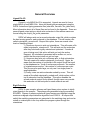
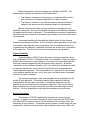
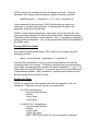
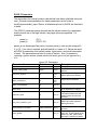
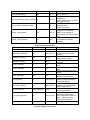
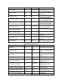
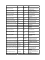
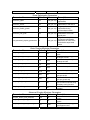
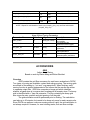
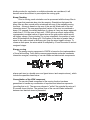
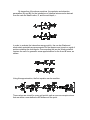
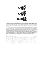
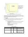
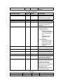
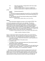
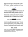
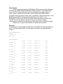
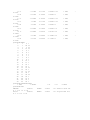
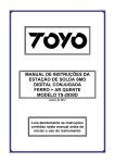
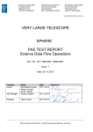
DOCK 5.4 User Manual
Irwin D. Kuntz
Demetri T. Moustakas
P. Therese Lang
© University of California 2006
Last updated March 2006
General Overview
Ligand File I/O
Currently, only MOL2 file I/O is supported. Ligands are read in from a
single MOL2 or multi-MOL2 file. Atom and bond types are assigned using the
DOCK 4 atom/bond typing parameter files (vdw.defn, flex.defn, flex_table.defn).
More information about all of these files can be found in the Appendix. There are
several ligand output options, which write molecules to files whose names are
formed using the output_file_prefix parameter:
DOCK will always write out a scored molecules output file, which contains
the best scoring pose for each molecule in the database. This will create a file
called outputprefix_scored.mol2. Beyond this option, there are several other
levels of sampling output:
1) Users can choose to write out orientations. This will create a file
called outputprefix_orients.mol2. This will write out the molecules
after they have been rigidly oriented and optimized. If anchor &
grow is being used, this option will write out only the anchor
fragment. All orientations generated will be written out, so be
careful that the output does not get too huge.
2) Users can also write out conformers prior to final optimization.
This will create a file called outputprefix_confs.mol2. Again, be
aware that the number of molecules in the output file will be equal
to the database size * the # of anchors per molecule * the number
of orientations per anchor * the number of conformers per cycle.
This file can grow quite large, so only use it on single poses or
small databases.
3) Finally, users can write molecules ranked by score. This will
create a file called outputprefix_ranked.mol2, which writes out the
top N molecules from the database. This option disables the
scored molecule output file by default, though users can override
this and write out the best pose for each molecule as well.
Rigid Orienting
DOCK 5 uses receptor spheres and ligand heavy atom centers to rigidly
orient ligands in the receptor. The spheres are generated using the accessory
SPHGEN. Cliques of receptor spheres & ligand centers are identified using the
maximum subgraph clique detection algorithm from DOCK 4. All cliques that
satisfy the matching parameters are generated in the matching step, and can be
sorted or ordered prior to the loop where the program cycles through the
orientations.
Both automated and manual matching are available in DOCK5. The
sphere/center matches are determined by 2 parameters:
1) The distance tolerance is the tolerance in angstroms within which a
pair of spheres is considered equivalent to a pair of centers
2) The distance minimum is the shortest distance allowed between 2
spheres (any sphere pair with a shorter distance is disregarded)
Manual matching will create as many matches as possible given the
specified parameters, and sort the matches according to the RMS error between
the spheres and centers in the match. The matches are provided as orientations
until either the max_orients # of orientations are reached, or the end of the match
list is reached.
Automated matching will start with the default values for the distance
tolerance and distance minimum. A list of matches will be generated, and if the #
of matches is less than the # max_orientations, then the distance tolerance is
increased and the matching is repeated until there are at least max_orientations
in the match list. Then the list is sorted, and orientations are generated.
Ligand Flexibility
Ligand flexibility in DOCK 5 uses the anchor-and-grow algorithm, which
was introduced in DOCK 4. Rotatable bonds (not contained in rings) are used to
partition the molecule into rigid segments, from which all anchors that meet the
criteria are selected beginning with the largest anchor segment. All anchor
orientations (or the starting orientation only, if no orienting is selected) are used
as starting configurations onto which the first flexible layer is appended and
conformationally expanded. The total population of conformers is then reduced
to the number specified by num_confs_per_cycle, and the process is repeated
until the last layer is reached.
The conformer generator class now integrates score optimization in the
anchor & grow algorithm. The anchors can be rigidly optimized, the final
conformations can be rigidly, torsionally, or completely optimized, and the
partially grown conformers can be completely optimized. The anchor & grow
steps use whichever scoring function the user selects as the primary scoring
function. The final minimization step uses the secondary scoring function.
Scoring Functions
This release of DOCK5 implements a hierarchical scoring function
strategy. A master score class manages all scoring functions that DOCK uses.
Any of the DOCK scoring functions can be selected as the primary and/or the
secondary scoring function. The primary scoring function is used during the rigid
minimization, and anchor & grow steps, which typically make many calls to the
scoring function. The secondary scoring function is used in the final
minimization, scoring, and ranking of the molecules. If no secondary scoring
function is selected, the primary scoring function is used as the secondary.
This release contains continuous molecular mechanics based scoring
(vdw + columbic terms only), grid-based molecular mechanics scoring, contact
scoring and bump filtering as implemented in DOCK 4. Scoring grids are created
using the GRID program. DOCK also contains GB/SA scoring, as implemented
in SDOCK. Scoring grids for the GBSA code are calculated using the
accessories nchemgrid_GB and nchemgrid_SA.
This release also includes an internal energy scoring function, which is
used during the anchor & grow flexible search. This function computes the
Lennard-Jones and columbic energy between all ligand atom pairs, excluding all
1-2, 1-3, and 1-4 pairs. This energy is not included in the final reported score.
Score Optimization
Score optimization is implemented using a simplex minimizer based on
the DOCK 4 minimizer. Users can choose to minimize the rigid anchors,
minimize during flexible growth, and minimize the final conformation. The anchor
minimization is always done rigidly; also, if no flexible growth is being done, this
step will minimize the entire molecule. The minimization during the flexible
growth is a complete (torsions + rigid) minimization. The final minimization can
be rigid or torsions only, or complete. When the simplex “shrinks” enough so that
the highest and lowest points are within the scoring tolerance or if the number of
requested minimizer steps is reached, the minimizer terminates.
Using DOCK
Installing DOCK
1. Save file for appropriate operating system to hard drive.
2. Uncompress the archive into a folder called dock5/ in a directory of your
choice.
a. For windows systems, a Zip file is provided
b. For *nix systems, a gzipped archive is provided
3. All DOCK 5 binaries are installed in dock5/bin/
The dock5 directory contains the following subdirectories:
bin/
demo/
installation/
parameters/
src/
utilities/
accessories/
grid/
GBSA_Grids/
Compiling DOCK (if required)
DOCK comes with platform specific compiled binaries. You should not need to
compile the code or accessories unless you have made changes to the source
code, or are planning to run DOCK on a platform for which we do not distribute
binaries.
Building DOCK: (all platforms)
From the dock5 directory:
cd config/
./configure gnu
make
DOCK with mpi function is built upon an mpi library. The MPICH library is
provided freely by Argonne National Labs (http://wwwunix.mcs.anl.gov/mpi/mpich/). The MPI library needs to be installed and running
on the system if the MPI features are to be used. Once MPI is installed, you
need to define MPICH_HOME as an environment variable.
Building MPI-DOCK (all platforms):
From the dock5 directory:
cd config/
./configure gnu.parallel
make
NOTE: MPI-DOCK 5.4 has been compiled with MPICH-1.2.7 on all supported
platforms (MPICH-1.2.5 for WinXP).
Running DOCK
For Windows Users:
DOCK and its accessories must be run using a Linux-like
environment like Cygwin (http://www.cygwin.com/). When you
install your emulator, make sure to also install compilers and unix
shells (“Devel” for Cygwin).
DOCK must be run command line from a standard unix shell. It reads a
parameter file containing field/value pairs using the following command:
dock5/bin/dock5 -i parameter.in [-v1] [-v2] [-o outputfile.txt]
If the parameter file does not exist, DOCK will generate one using your
responses to the parameter questions. If the parameter file exists, any
parameter values found will be read.
DOCK 5 outputs the job parameters to the screen at the start of the job, and
prints summary information for each molecule processed. Additional summary
information will be included in future releases. The –v1 flag prints a histogram of
sphere matching information. The –v2 flag prints details about the breakdown of
the GB/SA terms.
Running DOCK in Parallel
If you have installed the MPI library, DOCK can be run in parallel using the
following command:
mpirun –np # dock5.mpi -i parameter.in –o outputfile.txt
Note that that parallezation is set up to have a single Master node with the
remaining nodes act as slaves. The Master node performs file processing and
input/output, whereas the slaves perform the actual calculations. If –np = 1, the
code defaults to non-MPI behavior. As a result, there will be minimal difference
in performance between 1 and 2 processors. Improved performance will only
become evident with more than 2 nodes.
Running the Demo
DOCK 5.4 includes two demonstration files that are designed to test your
installation. These demos must also be run command-line.
For DOCK: (all platforms)
From the dock5 directory:
cd demo
./script_clean
./script_demo
For MPI-DOCK: (all platforms)
From the dock5 directory:
cd demo
./script_clean
./script_mpi_demo
NOTE: MPI-DOCK will be run on 4 processors for the demo
DOCK 5 Parameters
The parameters for several common calculations have been optimized using test
sets. General recommendations for these parameters can be found in
dock5/recommended_input. Below, all available options for DOCK are described
in detail.
The DOCK 5 parameter parser requires that the values entered for a parameter
exactly match one of the legal values if any legal values are specified. For
example:
param_a
param_b
[5] ():
[5] (0 5 10):
param_a can be assigned any value, however param_b can only be assigned 0,
5, or 10. If no value is entered, both will default to a value of 5. Below are listed
all DOCK 5 parameters, their default values, legal values, and a brief description
of each. The parameters are listed in order of function. Also, for questions
requiring a yes/no answer, please use the full word (yes or no) as opposed to y
or n.
Parameter Name
Ligand I/O Parameters
Default
Values Description
ligand_atom_file
database.mol2
string
ligand_outfile_prefix
output
string
limit_max_ligands
no
write_orientations
no
write_conformations
no
yes, no
initial_skip
0
int
calculate_rmsd
no
yes, no
use_rmsd_reference_mol
no
yes, no
rmsd_reference_filename
ligand_rmsd.mol2
string
rank_ligands
no
yes, no
bool
(yes,
no)
bool
(yes,
no)
The ligand input filename
The prefix that all output files
will use
The maximum # of ligands that
will be read in from a library
Flag to write orientations
Flag to write conformations
The # of molecules to skip over
at the beginning of a library
Flag to perform an RMSD
calculation between the final
molecule pose and its initial
structure.
Specify reference structure for
RMSD calculation (default is
starting structure)
File containing RMSD reference
structure
Flag to enable a ligand topscore list. These ligands will be
written to outfile_ranked.mol2,
and outfile_scored.mol2 will be
max_ranked_ligands
500
int
scored_conformer_output_override
no
yes, no
num_scored_conformers_written
1
int
cluster_conformations
yes
yes, no
cluster_rmsd_threshold
2.0
float
empty by default
The # of ligands to be stored in
the top score list
This flag causes all ligands to
be written to
outfile_scored.mol2, even when
rank_ligands is true
The # of scored poses for each
ligand printed to
output_scored.mol2
Flag to enable clustering of fully
minimized conformations
(NOTE: Only available if
num_scored_confomers_written
> 1)
The cutoff to determine whether
conformations should be
clustered
Parameter Name
Orient Ligand Parameters
Default
Values
Description
orient_ligand
yes
bool (yes, no)
automated_matching
yes
bool (yes, no)
distance_tolerence
0.25
float
distance_minimum
2.0
float
nodes_minimum
3
int
nodes_maximum
10
int
receptor_site_file
receptor.sph
string
max_orientations
500
int
critical_points
no
bool (yes, no)
chemical_matching
no
bool (yes, no)
chem_match_tbl
chem_match.tbl
string
use_ligand_spheres
no
bool (yes, no)
ligand_sphere_file
ligand.sph
string
Flexible Ligand Parameters
Flag to orient ligand to spheres
Flag to perform automated
matching instead of manual
matching
The distance tolerance applied
to each edge in a clique
The minimum size for an edge
in a clique
The minimum # of nodes in a
clique
The maximum # of nodes in a
clique
The file containing the receptor
spheres
The maximum # of orientations
that will be cycled through
Flag to use critical point sphere
labeling to target orientations
to particular spheres
Flag to use chemical “coloring”
of spheres to match chemical
labels on ligand atoms
File defining the legal chemical
type matches/pairings
Flag to enable a sphere file
representing ligand heavy
atoms to be used to orient the
ligand. Typically used for
macromolecular docking
Ligand spheres
Parameter Name
Default
Values
flexible_ligand
yes
bool (yes, no)
ag_conf_search
yes
bool (yes, no)
min_anchor_size
40
int
num_anchor_orients_for_growth
100
int
number_confs_for_next_growth
100
int
use_internal_energy
yes
bool (yes, no)
internal_energy_att_exp
6
int
internal_energy_rep_exp
12
int
internal_energy_dielectric
4.0
float
use_clash_overlap
no
bool (yes, no)
clash_overlap
0.5
float
Parameter Name
Description
Flag to perform ligand
conformational searching
Flag to use the anchor & grow
algorithm to search ligand
conformations
The minimum # of heavy
atoms for an anchor segment
The maximum number of
anchor orientations promoted
to the conformational search
The maximum number of
conformations carried forward
in the anchor & grow search
Flag to add an internal energy
term to the score during the
conformational search
VDW attractive exponent
VDW repulsive exponent
Dielectric used for electrostatic
calculation
Flag to check for overlapping
atom volumes during anchor
and grow
Percent of overlap allowed
before a clash is declared
Ligand Scoring Parameters
Default
Values
Description
bump_filter
yes
bool (yes,
no)
bump_grid_prefix
grid
string
max_bumps
2
int
score_molecules
yes
bool (yes,
no)
contact_score_primary
no
bool (yes,
no)
contact_score_secondary
no
bool (yes,
no)
contact_score_cutoff_distance
4.5
float
contact_score_clash_overlap
0.75
float
contact_score_clash_penalty
50
int
contact_score_grid_prefix
grid
string
Flag to perform bump filtering
The prefix to the grid file(s)
containing the desired bump
grid
The maximum allowed # of
bumps for a molecule to pass
the filter
Enables scoring of molecules
Flag to perform contact
scoring as the primary
scoring function
Flag to perform contact
scoring as the secondary
scoring function
The distance threshold
defining a contact
Contact definition for use with
intramolecular scoring
The penalty for each contact
overlap made
The prefix to the grid files
receptor.mol2
string
6
int
12
int
4.0
float
containing the desired cnt
grid
Flag to perform grid-based
energy scoring as the primary
scoring function
Flag to perform grid-based
energy scoring as the
secondary scoring function
Scalar multiplier of the vdw
energy component
Scalar multiplier of the
electrostatic energy
component
The prefix to the grid files
containing the desired nrg
grid
Flag to perform continuous
non-grid based scoring
Flag to perform continuous
non-grid based scoring
File that contains receptor
coordinates
VDW L-J potential attractive
exponent
VDW L-J potential repulsive
exponent
Dielectric constant for
electrostatic term
1
float
Scalar multiplier of vdw
energy component
grid_score_primary
yes
bool (yes,
no)
grid_score_secondary
yes
bool (yes,
no)
grid_score_vdw_scale
1
float
grid_score_es_scale
1
float
grid_score_grid_prefix
grid
string
continuous_score_primary
no
continuous_score_secondary
no
cont_score_rec_filename
cont_score_att_exp
cont_score_rep_exp
cont_score_dielectric
cont_score_vdw_scale
cont_score_es_scale
bool (yes,
no)
bool (yes,
no)
1
float
gbsa_pairwise_score_primary
no
bool (yes,
no)
gbsa_pairwise_score_secondary
no
bool (yes,
no)
gbsa_pairwise_gb_grid_prefix
gb_grid
string
gbsa_pairwise_sa_grid_prefix
sa_grid
string
gbsa_pairwise_vdw_grid_prefix
grid
string
gbsa_pairwise_screen_file
screen.in
string
gbsa_pairwise_solvent_dielectric
78.300003
float
Scalar multiplier of
electrostatic energy
component
Toggles whether or not to
use GB/SA scoring as the
primary scoring function
Toggles whether or not to
use GB/SA scoring as the
secondary scoring function
The path to the pairwise GB
grids
The path to the SA grids
The path to the dock4 nrg
grids, used for the vdw
portion of the GB/SA
calculation
GB parameter file for
electrostatic screening. Its
located in the parameters dir
by default
The value for the solvent
dielectric
Score Optimization Parameters
Default
Values
Description
Parameter Name
minimize_ligand
yes
bool (yes, no)
minimize_anchor
yes
bool (yes, no)
minimize_flexible_growth
yes
bool (yes, no)
minimize_final_pose
yes
bool (yes, no)
use_advanced_simplex_parameters
no
bool (yes, no)
Parameter Name
Flag to perform score
optimization
Flag to perform rigid
optimization of the anchor
Flag to perform complete
optimization during
conformational search
Flag to perform
minimization of the final
ligand pose
Flag to use a simplified set
of common minimization
parameters for each of the
minimization steps listed
above
Basic Simplex Minimizer Parameters
Default Values
Description
simplex_max_cycles
simplex_score_converge
simplex_cycle_converge
simplex_trans_step
simplex_rot_step
simplex_tors_step
simplex_anchor_max_iterations
simplex_grow_max_iterations
simplex_final_max_iterations
simplex_random_seed
1
int
0.1
float
1.0
float
1.0
float
0.1
float
10.0
float
500
int
500
int
0
int
0
int
Maximum # of minimization
cycles
Exit cycle at when energy
converges at cutoff
Exit minimization when cycles
converge at cutoff
Initial translation step size
Initial rotation step size
Initial torsion angle step size
Maximum # of iterations per
cycle per anchor
Maximum # of iterations per
cycle per growth step
Maximum # of iterations per
cycle for entire molecule using
secondary scoring function
Seed for random number
generator
Advanced Simplex Minimizer Parameters
Parameter Name
Default Values
Description
simplex_anchor_max_iterations
simplex_anchor_max_cycles
simplex_anchor_score_converge
simplex_anchor_cycle_converge
50
int
1
int
0.1
float
1.0
float
Maximum # of minimization
cycles
Maximum # of minimization
cycles
Exit cycle at when energy
converges at cutoff
Exit minimization when cycles
simplex_anchor_trans_step
simplex_anchor_rot_step
simplex_anchor_tors_step
1.0
float
0.1
float
10.0
float
converge at cutoff
Initial translation step size
Initial rotation step size
Initial torsion angle step size
NOTE: Repeat for minimization of each layer (simplex_grow_xxx) and final minimization
(simplex_final_xxx)
Parameter Name
Atom & Bond Typing Parameters
Default
Legal
Description
atom_model
all
string (all, united)
vdw_defn_file
vdw.defn
string
flex_defn_file
flex.defn
string
flex_drive_file
flex_drive.tbl
string
chem._defn_file
chem.defn
string
Choice of all atom or united
atom models
File containing vdw
parameters for atom types
File containing bond definition
parameters
File containing conformational
search parameters
File containing chemical label
(pharmacophore) definitions
ACCESSORIES
GRID
Author: Todd Ewing
Based on work by Elaine Meng and Brian Shoichet
Overview
GRID creates the grid files necessary for rapid score evaluation in DOCK.
Two types of scoring are available: contact and energy scoring. The scoring grids
are stored in files ending in *.cnt and *.nrg respectively. When docking, each
scoring function is applied independent of the others and the results are written
to separate output files. GRID also computes a bump grid which identifies
whether a ligand atom is in severe steric overlap with a receptor atom. The bump
grid is identified with a *.bmp file extension. The file containing the bump grid
also stores the size, position and grid spacing of all the grids.
The grid calculation must be performed prior to docking. The calculation
can take up to 45 minutes, but needs to be done only once for each receptor site.
Since DOCK can perform continuum scoring without a grid, the grid calculation is
not always required. However, for most docking tasks, such as when multiple
binding modes for a molecule or multiple molecules are considered, it will
become more time efficient to precompute the scoring grids.
Bump Checking
Prior to scoring, each orientation can be processed with the bump filter to
reject ones that penetrate deep into the receptor. Orientations that pass the
bump filter are then scored and/or minimized with any of the available scoring
functions. A bump is based on the sum of the van der Waals radii of the two
interacting atoms. The user specifies what fraction of the sum is considered a
bump. For example, the default definition of a bump is if any two atoms approach
closer than 0.75 of the sum of their radii. GRID stores an atomic radius which
corresponds to smallest radius of ligand atom at the grid position which would
still trigger a bump. During docking, for a given orientation, the position of each
atom is checked with the bump grid. If the radius of the atom is greater than or
equal to the radius stored in the bump grid, then the atom triggers a bump. To
conserve disk space, the atom radius is multiplied by 10 and converted to a short
unsigned integer.
Energy scoring
The energy scoring component of DOCK is based on the implementation
of force field scoring. Force field scores are approximate molecular mechanics
interaction energies, consisting of van der Waals and electrostatic components:
75
where each term is a double sum over ligand atoms i and receptor atoms j, which
include the quantities listed below.
Generalization of the VDW component
The van der Waals component of the scoring function has been
generalized to handle any combination of repulsive and attractive exponents
(providing that a> b). The user may choose to "soften" the potential by using a 69 Lennard-Jones function. The general form of the van der Waals interaction
between two identical atoms is presented:
where ε is the well depth of the interaction energy, R is the van der Waals
radius of the atoms, and coefficients C and D can be determined given the two
following boundary conditions:
at
at
Application of these boundary conditions to the above equation yields an
expression of the van der Waals interaction with a generalized Lennard-Jones
potential.
The consequence of using a different exponent for the repulsive term is
illustrated in Figure 1. Notice that the well position and depth are unchanged, but
that the repulsive barrier has shrunk by about a 0.25 Angstrom.
Figure 1: Distance dependence of the Lennard-Jones Function
Precomputing potentials on a grid
By inspection of the above equations, the repulsion and attraction
parameters (Aij and Bij) for the interactions of identical atoms can be derived
from the van der Waals radius, R, and the well depth, ε.
In order to evaluate the interaction energy quickly, the van der Waals and
electrostatic potentials are precomputed for the receptor and stored on a grid of
points containing the docking site. Precomputing the van der Waals potential
requires the use of a geometric mean approximation for the A and B terms, as
shown:
Using this approximation, the first equation can be rewritten:
Three values are stored for every grid point k,each a sum over receptor atoms
that are within a user defined cutoff distance of the point:
These values, with trilinear interpolation, are multiplied by the appropriate ligand
values to give the interaction energy. GRID calculates the grid values and stores
them in files. The values are read in during a DOCK run and used for force field
scoring.
The user determines the location and dimensions of the grid box using the
program SHOWBOX. It is not necessary for the whole receptor to be enclosed;
only the regions where ligand atoms may be placed need to be included. The box
merely delimits the space where grid points are located, and does not cause
receptor atoms to be excluded from the calculation. Besides a direct specification
of coordinates, there is an option to center the grid at a sphere cluster center of
mass. Any combination of spacing and x, y, and z extents may be used.
Contact Scoring
Contact scoring in GRID incorporates the scoring performed with the DISTMAP
program developed by Shoichet and Bodian. The score is a summation of the
heavy atom contacts (every atom except hydrogen) between the ligand and
receptor. A contact is defined as an approach of two atoms within some cutoff
distance (usually 4.5 Angstroms). If the two atoms approach close enough to
bump (as identified with the bump grid) then the interaction can be penalized by
an amount specified by the user. The distance dependence of the contact score
is represented in Figure 2.
Figure 2. Distance dependence of contact score function
The attractive score in GRID is negative and a repulsive score is positive. This
switch of sign is necessary to allow the same minimization protocol to be used for
contact scoring as implemented for energy scoring.
Running GRID
GRID must be run command line from a standard unix shell. It reads a
parameter file containing field/value pairs using the following command:
grid -i grid.in [-stv] [-o grid.out]
-i input_file (Input parameters extracted from input_file, or grid.in if
not specified)
-o output_file (Output written to output_file, or grid.out if not
specified)
-s Input parameters entered interactively
-t Reduced output level
-v Increased output level
Parameter Name
General Parameters
Default Value
compute_grids
grid_spacing
no
0.3
bool (yes, no)
float
Flag to compute scoring grids
The distance between grid
points along each axis.
output_molecule
no
bool (yes, no)
Flag to write out the
coordinates of the receptor into
a new, cleaned-up file. Atoms
are resorted to put all residue
atoms together. Terminal
SYBYL capping groups are
Description
merged with the terminal
residues.
Parameter Name
Scoring Parameters
Default Value
Description
contact_score
contact_cutoff_distance
no
4.5
bool (yes, no)
float
chemical_score
energy_score
energy_cutoff_distance
no
no
10
bool (yes, no)
bool (yes, no)
float
atom_model
u
string (u, a)
attractive_exponent
6
int
repulsive_exponent
12
int
distance_dielectric
yes
bool (yes, no)
dielectric_factor
bump_filter
4.0
no
float
bool (yes, no)
bump_overlap
0.75
float
Flag to construct contact grid
Maximum distance between
heavy atoms for the interaction
to be counted as a contact
Flag to construct chemical grid
Flag to perform energy scoring
Maximum distance between
two atoms for their contribution
to the energy score to be
computed
Flag for how to model of
nonpolar hydrogens
u = United atom model.
Hydrogens attached to
carbons are assigned a
zero VDW well-depth
and
the partial charge is
transferred to the
carbon.
a = All atom model.
Hydrogens attached to
carbons have regular
VDW well-depth and
partial charge is not
modified.
Exponent of attractive LennardJones term for VDW potential
Exponent of repulsive LennardJones term for VDW potential
Flag to make the dielectric
depend linearly on the distance
Coefficient of the dielectric
Flag to screen each orientation
for clashes with receptor prior
to scoring and minimizing
Amount of VDW overlap
allowed. If the probe atom and
the receptor heavy atom
approach closer than this
fraction of the sum of their VDW
radii, then the position is
flagged as a bump.
0 = Complete overlap allowed.
1 = No overlap allowed
File Input
Value
Parameter Name
Default
receptor_file
receptor.mol2
bool (yes, no)
Description
Receptor coordinate file.
box_file
site_box.pdb
float
vdw_definition_file
vdw.defn
string
Partial charges and atom
types need to be present.
File containing SHOWBOX
output file which specifies
boundaries of grid
VDW parameter file.
File Output
Value
Parameter Name
Default
score_grid_prefix
grid
string
receptor_out_file
receptor_out.mol2
string
Description
Core file name of grids (file
extension will be appended
automatically)
File for cleaned-up receptor
when output_molecule set
NCHEMGRID_GB and NCHEMGRID_SA
Author: Xiaoqin Zou
Overview
The NCHEMGRID_GB and NCHEMGRID_SA programs create the GB and SA
receptor grids for use with DOCK 5's GB/SA scoring function.
Input
Both programs require that an INCHEM file be created in the working
directory, which contains the parameters to control the program. The INCHEM
parameters for both the NCHEMGRID_GB and NCHEMGRID_SA programs are
detailed below:
For NCHEMGRID_GB:
receptor.pdb
cavity.pdb
parameters/prot.table.ambcrg.ambH
parameters/vdw.parms.amb
box.pdb
0.4
2
1
8.0 8.0
78.3 78.3
solvent,cavity
2.3 2.8
output_prefix
1
; receptor pdb file
; cavity pdb file
; charge parameter file
; VDW parameter file
; box pdb file
; grid spacing in angstroms
; es type: GB
; es scale for ff scoring
; cutoff for es and outer box
; dielectric of
; bumping distances
; output grid prefix name
; pairwise calculation
NOTE: The cavity.pdb file should be an empty file. This feature is not frequently
used. However, the parameter must still be passed. The pairwise calculation
value must also always be 1.
For NCHEMGRID_SA:
receptor.pdb
pararameters/prot.table.ambcrg.ambH
parameters/vdw.parms.amb
box.pdb
0.4
1.4
2
8.0
output_prefix
; receptor pdb file
; charge parameter file
; VDW parameter file
; box pdb file
; grid spacing in angstroms
; probe radius for SA
; scoring type: SA
; cutoff for SA calculations
; output grid prefix name
SPHGEN
Author: Irwin D. Kuntz
Modified by: Renee DesJarlais, Brian Shoichet
Overview
SPHGEN generates sets of overlapping spheres to describe the shape of
a molecule or molecular surface. For receptors, a negative image of the surface
invaginations is created; for a ligand, the program creates a positive image of the
entire molecule. Spheres are constructed using the molecular surface described
by Richards (1977) calculated with the program dms (www.cgl.ucsf.edu). Each
sphere touches the molecular surface at two points and has its radius along the
surface normal of one of the points. For the receptor, each sphere center is
“outside” the surface, and lies in the direction of a surface normal vector. For a
ligand, each sphere center is “inside” the surface, and lies in the direction of a
reversed surface normal vector. Spheres are calculated over the entire surface,
producing approximately one sphere per surface point. This very dense
representation is then filtered to keep only the largest sphere associated with
each receptor surface atom. The filtered set is then clustered on the basis of
radial overlap between the spheres using a single linkage algorithm. This creates
a negative image of the receptor surface, where each invagination is
characterized by a set of overlapping spheres. These sets, or “clusters,” are
sorted according to numbers of constituent spheres, and written out in order of
descending size. The largest cluster is typically the ligand binding site of the
receptor molecule. The program showsphere writes out sphere center
coordinates in PDB format and may be helpful for visualizing the clusters.
Input
rec.ms
R
X
#molecular surface file
#sphere outside of surface (R) or inside surface (L)
#specifies subset of surface points to be used (X=all points)
0.0
4.0
1.4
#prevents generation of large spheres with close surface
contacts (default=0.0)
#maximum sphere radius in Angstroms (default=4.0)
#minimum sphere radius in Angstroms (default=radius of
probe)
rec.sph
#clustered spheres file
NOTES:
1) The input file names and parameters are read from a file called INSPH,
which should not contain any blank lines or the comments (denoted by #)
from above.
2) The molecular surface file must include surface normals. SPHGEN
expects the Fortran format
(A3, I5, X, A4, X, 2F8.3, F9.3, X, A3, 7X, 3F7.3).
Output
Some informative messages are written to a file called OUTSPH. This
includes the parameters and files used in the calculation. The spheres
themselves are written to the clustered spheres file. They are arranged in
clusters with the cluster having the largest number of spheres appearing first.
The sphere cluster file consists of a header followed by a series of sphere
clusters. The header is the line “DOCK 3.5 receptor_spheres” followed by a color
table. The color table contains color names (format A30) each on a separate line.
As SPHGEN produces no colors, the color table is simply absent.
The sphere clusters themselves follow, each of which starts with the line
cluster n number of spheres in cluster i
where n is the cluster number for that sphere cluster, and i is the number of
spheres in that cluster. Next, all spheres in that cluster are listed in the format
(I5, 3F10.5, F8.3, I5, I2, I3) where the values correspond to, respectively,
• The number of the atom with which surface point i (used to generate the
sphere) is associated.
• The x, y,and z coordinates of the sphere center.
• The sphere radius.
• The number of the atom with which surface point j (second point used to
generate the sphere) is associated.
• The critical cluster to which this sphere belongs.
• The sphere color. The color is simply an index into the color table that was
specified in the header. Therefore, 1 corresponds to the first color in the
header, 2 for the second, etc. 0 corresponds to unlabeled.
The clusters are listed in numerical order from largest cluster found to the
smallest. At the end of the clusters is cluster number 0. This is not an actual
sphere cluster, but a list of allof the spheres generated whose radii were larger
than the minimum radius, before the filtering heuristics ( i.e. allowing only one
sphere per atom and using a maximum radius cutoff) and clustering were
performed. Cluster 0 may be useful as a starting point for users who want to
explore a wider range of possible clusters than is provided by the standard
SPHGEN clustering routine. The program creates three temporary files:
temp1.ms, temp2.sph, and temp3.atc. These are used internally by SPHGEN,
and are deleted upon completion of the computation. For more information on
sphere generation and selection, go to the demo.
SHOWBOX
Author: Elaine Meng
SHOWBOX is an interactive program that allows visualization of the location and
size of the grids that will be calculated by the program grid, using any graphics
program that can display PDB format. The user is asked whether the box should
be automatically constructed to enclose all of the spheres in a cluster. If so, the
user must also enter a value for how closely the box faces may approach a
sphere center (how large a “cushion” of space is desired) and the sphere cluster
filename and number. If not, the user is asked whether the box will be centered
on manually entered coordinates or a sphere cluster center of mass. Depending
on the response, the coordinates of the center or the sphere cluster filename and
number are requested. Finally, the user must enter the desired box dimensions
(if not automatic) and a name for the output PDB-format box file.
SHOWSPHERE
Authors: Stuart Oatley, Elaine Meng, Daniel Gschwend
SHOWSPHERE is an interactive program; it produces a PDB-format file of
sphere centers and an MS-like file of sphere surfaces, given the sphere cluster
file and cluster number. The surface file generation is optional. The user may
specify one cluster or “all,” and multiple output files will be generated, with the
cluster number appended to the end of the name of each file. The input cluster
file is created using SPHGEN. SHOWSPHERE requests the name of the sphere
cluster file, the number of the cluster of interest, and names for the output files.
Information is sent to the screen while the spheres are being read in, and while
the surface points are being calculated.
SPHERE_SELECTOR
Author: P. Therese Lang
SPHERE_SELECTOR will take the ouput from SPHGEN and select all spheres
with a user-defined radius of a target molecule. The target molecule can be
anything (ie known ligand, receptor residue, ect) as long as it is in proper MOL2
format. The required input for sphere_selector is:
USAGE: sphere_selector <sphere_cluster_file.sph> <set_of_atoms.mol2>
<radius>
Please note that above order of input files must be maintained for the program to
work.
APPENDIX 1: Parameter File Formats
Overview
The parameter files contain atom and bond data needed during DOCK
calculations. The definition (*.defn) files contain atom and bond labeling data.
The table (*.tbl) files contain additional data for chemical interactions and flexible
bond torsion positions. They may be edited by the user.
Atom Definition Rules
The definition files use a consistent atom labeling convention for which an
atom in virtually any chemical environment can be identified. The specification of
adjacent atoms is nested using the elements listed below.
•
•
•
Each element must be separated by a space.
If more than one adjacent atom is specified, then ALL must be
present (i.e. a boolean AND for rules within a line).
If a label can have multiple definition lines, then any ONE of
them must be satisfied for inclusion (i.e. a boolean OR for rules
on different lines).
Element
atom type
( )
[ ]
integer
Example
C.2 ( 2 O.co2 )
.3 [ 3 H ]
Atom Definition Elements
Function
Specifies partial or complete atom type. A partial
specification is more general (i.e. "C" versus "C.3"). An
asterisk (*) specifies ANY atom type.
Specifies atoms that must be bonded to parent atom.
Specifies atoms that must NOT be bonded to parent
atom.
Specifies the number of an atom that must be bonded.
Example Definitions
Explanation
A carboxylate carbon.
Any sp3 hybridized atom that is not attached to
three hydrogens.
C. [ O. ] [ N. [ 2 O.2 ] [ 2 C. ] ]
Any carbon not attached to an oxygen or a
nitrogen (unless the nitrogen is a nitro or
tertiary nitrogen).
vdw.defn
This file contains atom labels and definitions for van der Waals atom typing.
• The following data types are associated with each atom: VDW
radius, VDW well-depth, flag for heavy atom, number of
attached atoms.
• Some labels are used only for the united-atom model, some for
only the all-atom model, and some for either.
• A label may have multiple definitions.
Sample Entries from vdw.defn
_____________________________________
name Carbon_sp/sp2
atom_model either
radius 1.850
well_depth 0.120
heavy_flag 1
valence 4
definition C
_____________________________________
name Carbon_All_sp3
atom_model all
radius 1.800
well_depth 0.060
heavy_flag 1
valence 4
definition C.3
_____________________________________
name Carbon_United_CH3
atom_model united
radius 2.000
well_depth 0.150
heavy_flag 1
valence 4
definition C. ( 3 H )
_____________________________________e
chem.defn
This file contains labels and definitions for chemical labeling.
• Nothing in addition to a label is assigned to an atom.
• A label may have multiple definition lines.
Sample Entries from chem.defn
______________________________________________________
__
name hydrophobic
definition C. [ O. ] [ N. [ 2 O.2 ] [ 2 C. ] ] ( * )
definition N.pl3 ( 3 C. )
definition Cl ( C. )
definition Br ( C. )
definition I ( C. )
definition C.3 [ * ]
________________________________________________________
name donor
definition N. ( H )
definition N.4 [ * ]
________________________________________________________
name acceptor
definition O. [ H ] [ N. ] ( * )
definition O.3 ( 1 * ) [ N. ]
definition O.co2 ( C.2 ( O.co2 ) )
definition N. [ H ] [ N. ] [ O. ] [ 3 . ] ( * )
definition O.2 [ * ]
________________________________________________________
chem_match.tbl
This file contains the interaction matrix for which chemical labels can form an
interaction in matching.
• The labels must be identical to labels in chem.defn.
• The table flag indicates the beginning of the interaction table.
• Compatible labels are identified with a one, otherwise a zero.
Sample of chem_match.tbl
label null
label hydrophobic
label donor
label acceptor
label polar
table
1
1
1
1
0
1
1
0
0
1
1
0
1
1
nual Parameter Files
1
flex.defn
This file contains labels and definitions for flexible bond identification.
• The drive_id field corresponds to a torsion type in the
flex_drive.tbl file.
• The minimize field is a flag for whether the bond may be
minimized.
• Two definition lines must be present. Each definition
corresponds to an atom at either end of the bond.
Sample Entries from flex.defn
________________________________________
name sp3-sp3
drive_id 3
minimize 1
definition .3 [ 3 H ] [ 3 O.co2 ]
definition .3 [ 3 H ] [ 3 O.co2 ]
________________________________________
name sp3-sp2
drive_id 4
minimize 1
definition .3 [ 3 H ] [ 3 O.co2 ]
definition .2 [ 2 H ] [ 2 O.co2 ]
________________________________________
name sp2-sp2
drive_id 2
minimize 0
definition .2 [ 2 H ] [ 2 O.co2 ]
definition .2 [ 2 H ] [ 2 O.co2 ]
________________________________________
flex_drive.tbl
This file contains torsion positions assigned to each rotatable bond when the
flexible docking parameter is used in DOCK.
• The drive_id field corresponds to each torsion type.
• The positions field specifies the number of torsion angles to
sample.
• The torsions field specifies the angles that are sampled.
Sample Entries from flex_drive.defn
_________________________________________
drive_id 2
positions 2
torsions 0 180
_________________________________________
drive_id 3
positions 3
torsions -60 60 180
_________________________________________
drive_id 4
positions 4
torsions -90 0 90 180
_________________________________________
APPENDIX 2: Molecular File Formats
Tripos MOL2 format
Overview
This format is used for general molecule input and output of DOCK. This
format has the advantage of storing all the necessary information for atom
features, position, and connectivity. It is also a standardized format that other
modeling programs can read.
Specification
Of the many record types in a MOL2 file, DOCK recognizes the following:
MOLECULE, ATOM, BOND, SUBSTRUCTURE and SET. In the MOLECULE
record, DOCK utilizes information about the molecule name and number of
atoms, bonds, substructures and sets. In the ATOM record DOCK utilizes
information about the atom names, types, coordinates, and partial charges. In the
BOND record, DOCK utilizes the atom identifiers for the bond. In the
SUBSTRUCTURE record, DOCK records the fields, but does not utilize them.
The SET records are entirely optional. They are used only in special
circumstances, like when the use wants to define the anchor for flexible docking.
Please refer to Sybyl documentation for additional information.
Example
This example file illustrates all the elements of the MOL2 file read and written by
dock. It includes optional SET records which are used by the ligand flexibility
routines.
@<TRIPOS>MOLECULE
example
23
23
1
GAST_HUCK
@<TRIPOS>ATOM
1 C
0.0529
2 H
0.0571
3 C
0.0242
4 C
0.0319
5 H
0.0598
6 H
0.0598
7 N
0.3075
8 H
0.1243
9 C
0.0136
10 H
0.0390
11 H
0.0390
12 H
0.0390
13 C
0.0529
14 H
0.0571
0
2
1.2300
0.7100
0.0000 C.ar
1 ABC
2.1620
1.2490
0.0000 H
1 ABC
0.0000
1.4200
0.0000 C.ar
1 ABC
0.0000
2.9060
0.0000 C.3
1 ABC
-0.5150
3.2700
0.8920 H
1 ABC
-0.5150
3.2700
-0.8920 H
1 ABC
1.3680
3.3900
0.0000 N.3
1 ABC
1.8480
3.0500
0.8320 H
1 ABC
1.3680
4.8410
0.0000 C.3
1 ABC
0.8530
5.2050
0.8920 H
1 ABC
0.8530
5.2050
-0.8920 H
1 ABC
2.3990
5.2050
0.0000 H
1 ABC
-1.2300
0.7100
0.0000 C.ar
1 ABC
-2.1620
1.2490
0.0000 H
1 ABC
-
-
-
-
-
15 C
-1.2300
-0.7100
0.0000 C.ar
1 ABC
0.0471
16 H
-2.1620
-1.2490
0.0000 H
1 ABC
0.0655
17 C
-0.0000
-1.4200
0.0000 C.ar
1 ABC
0.0547
18 C
1.2300
-0.7100
0.0000 C.ar
1 ABC
0.0471
19 H
2.1620
-1.2490
0.0000 H
1 ABC
0.0655
20 C
-0.0000
-2.7800
0.0000 C.2
1 ABC
0.2555
21 O
-0.0850
-3.5030
0.9750 O.2
1 ABC
0.3604
22 O
0.1090
-3.2660
-1.2480 O.3
1 ABC
0.2944
23 H
0.1010
-4.2400
-1.1490 H
1 ABC
0.2522
@<TRIPOS>BOND
1
1
2 1
2
1
18 ar
3
1
3 ar
4
3
13 ar
5
3
4 1
6
4
6 1
7
4
5 1
8
4
7 1
9
7
8 1
10
7
9 1
11
9
12 1
12
9
11 1
13
9
10 1
14
13
14 1
15
13
15 ar
16
15
16 1
17
15
17 ar
18
17
20 1
19
17
18 ar
20
18
19 1
21
20
21 2
22
20
22 1
23
22
23 1
@<TRIPOS>SUBSTRUCTURE
1 ABC
1 GROUP
0 A
****
0 ROOT
@<TRIPOS>SET
ANCHOR
STATIC
ATOMS
<user>
**** Anchor atom set
6 1 3 13 15 17 18
RIGID
STATIC
BONDS
<user>
**** Rigid bond set
6 2 3 4 15 17 19
-
-
-