1
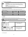
.
CONTENTS
1
1.1
1.2
1.3
INTRODUCTION ..................................................................................................... 4
General ...........................................................................................................................................4
Graphic Marking of Instructions .....................................................................................................4
AMENDMENTS TO THE MANUAL ...............................................................................................4
2
3
TYPE IDENTIFICATION OF BLOWERS ................................................................ 5
SAFETY INSTRUCTIONS ...................................................................................... 5
3.1
Requirements for Qualification of Personnel (COMPANIES) ........................................................5
3.1.1 General .....................................................................................................................................5
3.1.2 Installation .................................................................................................................................5
3.1.3 Maintenance and Troubleshooting ...........................................................................................5
Safe Installation Principles .............................................................................................................6
Personal Protection Equipment......................................................................................................6
Marking ...........................................................................................................................................6
3.4.1 General .....................................................................................................................................6
3.4.2 Name Plates .............................................................................................................................6
3.4.3 Safety symbols .........................................................................................................................6
3.4.4 Other symbols ...........................................................................................................................7
Prohibited use ................................................................................................................................7
Regulations and Standards ............................................................................................................7
3.6.1 Engineering Regulations and Standards ..................................................................................7
3.6.2 Operating Regulations and Standards .....................................................................................7
3.2
3.3
3.4
3.5
3.6
4
5
5.1
5.2
6
6.1
6.2
7
USE ......................................................................................................................... 7
DESCRIPTION AND FUNCTION............................................................................ 8
General ...........................................................................................................................................8
ROTARY BLOWER ........................................................................................................................8
TECHNICAL SPECIFICATIONS............................................................................. 8
BASIC DIMENSIONS AND WEIGHT.............................................................................................8
TECHNICAL SPECIFICATIONS ....................................................................................................9
INSTALLATION CONDITIONS............................................................................... 9
7.1
7.2
7.3
7.4
7.5
General ...........................................................................................................................................9
CONDITIONS OF THE ENVIRONMENT .......................................................................................9
POSITION OF THE BLOWER .......................................................................................................9
Vibrations .......................................................................................................................................9
Suction part ..................................................................................................................................10
7.5.1 Filtration ..................................................................................................................................10
7.5.2 Air Intake .................................................................................................................................10
7.6
Discharge Part ..............................................................................................................................10
7.6.1 Check Valve ............................................................................................................................10
7.6.2 Relief Valve .............................................................................................................................10
7.6.3 Combined Relief and Start-up Valve ......................................................................................10
7.6.4 Discharge Silencer..................................................................................................................10
7.7
POWER UNIT ..............................................................................................................................10
7.8
Piping Connection ........................................................................................................................11
8
HANDLING, TRANSPORT AND STORAGE ........................................................ 11
8.1
8.2
Delivery Contents .........................................................................................................................11
Handling .......................................................................................................................................11
8.2.1 General ...................................................................................................................................11
8.2.2 Stacking or Forklift Trucks ......................................................................................................11
8.2.3 Crane ......................................................................................................................................11
8.3
Transport ......................................................................................................................................11
8.4
Storage .........................................................................................................................................12
9
9.1
9.2
9.3
9.4
INSTALLATION AND COMMISSIONING ............................................................ 12
General .........................................................................................................................................12
Transport to Place of Installation ..................................................................................................12
INCORPORATION IN THE FINAL DEVICE ................................................................................12
First Start-Up ................................................................................................................................13
10 OPERATION PROCEDURE ................................................................................. 14
10.1
10.2
General .........................................................................................................................................14
Operating Checks.........................................................................................................................14
2/19
11 MAINTENANCE AND REPAIRS .......................................................................... 14
11.1
11.2
11.3
General ......................................................................................................................................... 14
Maintenance Plan ........................................................................................................................ 15
Maintenance Procedures ............................................................................................................. 15
11.3.1 General Principles .................................................................................................................. 15
11.3.2 Safety...................................................................................................................................... 15
11.3.3 General Check ........................................................................................................................ 15
11.3.4 Oil Charge for Rotary Blower .................................................................................................. 16
11.4
Failures and Troubleshooting....................................................................................................... 17
11.4.1 Summary of Failures .............................................................................................................. 17
11.5
Spare Parts .................................................................................................................................. 17
11.5.1 General ................................................................................................................................... 17
12 SERVICING .......................................................................................................... 17
13 DISASSEMBLY AND DISPOSAL ........................................................................ 18
14 CONDITIONS FOR ACCEPTANCE OF REPAIRS UNDER WARRANTY ........... 18
3/19
1 INTRODUCTION
1.1 GENERAL
This manual will provide you with a thorough acquaintance with an uncompleted machine (a blower) and ensure
its safe and trouble-free installation and operation.
Compliance with this manual during the entire service life of this blower will ensure that during the installation
and the subsequent use of the blower the safety rules will be observed at a level that corresponds to the
currently applicable safety standards and regulations and correct technical practice.
This manual is not intended to deal with either the hazards or the risks resulting from the improper installation or
utilisation of the blower for unintended purposes, nor any hazards and risks that might arise from specific local
conditions. Protection against these dangers and risks must be included in the local operating and safety
regulations.
It is necessary to become familiarised with this manual prior to the installation of the blower. Do not carry out
these activities before careful studying this direction and understanding all the instructions included.
Read this manual carefully prior to using the blower and in the case of any uncertainty contact the
KUBÍČEK VHS, s.r.o. company or an authorised service agent.
1.2 GRAPHIC MARKING OF INSTRUCTIONS
Very important instructions and warnings in this direction for use are marked in the following manner:
Non-observance of these instructions could cause risk to persons or to property.
Forbidden activities.
Non-observance of these instructions could cause damage to the equipment.
Other important instructions.
1.3 AMENDMENTS TO THE MANUAL
Any amendment to this manual may be made only by KUBÍČEK VHS, s.r.o. or based on the written consent of
the company.
4/19
2
TYPE IDENTIFICATION OF BLOWERS
The individual types, variants and sizes of the unit are designated using a code according to the following chart:
3D
..
..
..
the type of rotary blower used (three-lobe)
mode (without designation – overpressure, B – under pressure, with extra
suction)
size of the rotary blower, defined according to the input shaft diameter in
mm.
width of rotary blower housing defined using (A, B, C, S) code
3 SAFETY INSTRUCTIONS
3.1 REQUIREMENTS FOR QUALIFICATION OF PERSONNEL (COMPANIES)
3.1.1 General
To adequately ensure personal safety and the subsequent trouble-free operation of the blower, individual
activities related to the assembly and the subsequent usage of the blower must be carried out only by persons
(companies) with the relevant expertise.
- For the assurance of security it is important to ensure that individual functions are
executed by
persons (companies) with the requisite competences.
3.1.2 Installation
Installation of the uncompleted machinery can be carried out only by persons who fulfil the following
requirements:
•
relevant professional qualifications for the installation of machinery
•
relevant experience with the installation of machinery
•
familiarity with this direction for use.
Installation can be ordered from the KUBÍČEK VHS, s.r.o. company or from an authorised service
representative.
3.1.3 Maintenance and Troubleshooting
Only persons complying with the following requirements are allowed to service and troubleshoot the unit in the
extent specified in section 11 of this direction:
•
physical and mental qualification to carry out the specified activities
•
proven familiarity with this manual
•
familiarity with generally valid and local operating and safety regulations
•
authorized by the keeper of the unit for these activities.
5/19
3.2
SAFE INSTALLATION PRINCIPLES
-
prior to the installation of the blower, familiarise yourself thoroughly with the contents
of this manual
Cary out only those activities, to which you are authorized by your superior.
When installing the unit, observe generally valid and local operating and safety
regulations.
Use generally valid safety procedures only.
Always use the prescribed personal protective equipment.
-
3.3 PERSONAL PROTECTION EQUIPMENT
Utilisation of personal protective equipment must be as defined by local operational and safety regulations. The
anticipated range of personal protective equipment to be utilised is defined in the following table:
Installation of the blower:
Danger
Protected part
Protective equipment
scratching, bumping
upper limbs
protective gloves
Danger
Protected part
Protective equipment
burns from hot surfaces
upper limbs
protective gloves
Maintenance of the blower:
3.4 MARKING
3.4.1 General
The blower is equipped with identification marking (rating plates) and safety marking.
Keep these markings legible and restore them if damaged.
3.4.2 Name Plates
Name plate sized 45 x 30 mm
placed on the blower housing
3D..19.., 3D..28..,
Name plate sized 75 x 30 mm
placed on the blower housing
3D..38.., 3D..45.., 3D..55..,
3D..60.., 3D..80.., 3D..90..,
3D..100..,
3.4.3 Safety symbols
6/19
Symbol
Meaning
marking of suspension
(lifting eye, holes)
3.4.4 Other symbols
Symbol
Meaning
sense of rotation of blower rotor
3.5
PROHIBITED USE
-
do not use the blower to transporting of combustible and/or explosive gases
do not use the blower to transport of mixtures of air and combustible substances
never use the blower in premises with potential presence of
air and combustible substances on the suction side
never use the blower when connected to piping, air reservoir (air chamber) etc.
with overpressure below the maximum permissible operating pressure of the unit
never use the blower when connected to a reservoir without its own
protection against excess over the max. operating pressure
3.6 REGULATIONS AND STANDARDS
3.6.1 Engineering Regulations and Standards
The blower has been designed and manufactured in accordance with the following standards and regulations:
•
Decree of the Government No. 176/2008 Coll., laying down technical requirements of machinery
(corresponding with the directive 2006/42/EC)
•
ČSN EN 1012-1 Compressors and vacuum pumps – Safety requirements. Part 1: Compressors
•
ČSN EN 1012-2 Compressors and vacuum pumps – Safety requirements. Part 1: Vacuum pumps
3.6.2 Operating Regulations and Standards
The manufacturer of the final unit is required to prepare a manual for the final unit in the extent required by the
Directive 2006/42/EC. During operation of the final unit it is necessary to comply with this manual and with all
the regulations and standards applicable in the country of the operator of the final unit, in particular in regard to:
•
work safety
•
operation of machineries
•
operation of electric equipment.
4 USE
The blower is designed for the transportation and compression of air or of other non-aggressive, noncombustible and non-explosive gases without mechanical additives. Any use for gases other than air must be
discussed with the manufacturer.
The blower must be operated under conditions stated in section 7 without exceeding maximum values stated on
the blower name plate. The quantity of medium corresponds to the blower speed and back-pressure in the
discharge piping (for overpressure see the catalogue). The air quantity can be controlled only by changing the
speed of the blower – electric motor. Throttle regulation of suction or discharge is impermissible!
7/19
5 DESCRIPTION AND FUNCTION
5.1 GENERAL
These are blowers that operate in overpressure and under-pressure modes.
5.2 ROTARY BLOWER
The blower serves as an overpressure (under-pressure) source. This is a Roots blower with three-lobe rotary
pistons (rotors). The shafts of rotary pistons are placed in rolling bearings and the mutual positions of rotors are
controlled by gearing. The bearings and gearings are lubricated with oil. The working area of pistons is not
lubricated. The suction and discharge flange of the blower is connected to the suction and discharge part of the
blower unit, the input shaft to the drive unit.
1) suction flange
2) discharge flange
3) input shaft
6 TECHNICAL SPECIFICATIONS
6.1 BASIC DIMENSIONS AND WEIGHT
type
DN/PN
a
b
c
e
f
h
Ø
l
m
kg
mm
3D19S
50/16
162 126
328
203
26
216
19
40
28
3D19A
50/16
172 136
348
203
26
216
19
40
34
3D19B
50/16
182 146
368
203
26
216
19
40
36
3D19C
50/16
202 166
408
203
26
216
19
40
40
3D28A
50/16
214 151
435
258
34
264
28
70
62
3D28B
80/16
236 172
478
258
34
264
28
70
69
3D28C
80/16
276 214
560
258
34
264
28
70
80
3D38B
100/16 272 204
561
297
42.6
320
38
85
109
3D38C
100/16 322 254
661
297
42.6
320
38
85
125
3D45B
150/16 320 239
664
360
53.3
360
45
105
164
3D45C
150/16 376 295
776
360
53.3
360
45
105
193
3D55B
150/16 375 282
757
430
67.5
400
55
100
270
3D55C
200/10 445 352
897
430
67.5
400
55
100
325
3D60B
200/10 455 336
941
534
84
500
60
150
480
3D60C
250/10 543 425 1118
534
84
500
60
150
550
3D80B
250/10 523 405 1108
652
106
630
80
180
755
3D80C
300/10 638 520 1338
652
106
630
80
180
980
3D90B
300/10 640 510 1375
770
135
630
90
225 1242
3D90C
400/10 793 664 1682
770
135
630
90
225 1575
800
100 225 2150
3D100B 400/10 782 702 1709 1000 167.5
3D100C 500/10 917 837 1979 1000 167.5 1000 100 225 2605
8/19
6.2 TECHNICAL SPECIFICATIONS
Basic technical specifications of blowers are available at www.kubicekvhs.cz, on the name plate and in
purchase contract.
Never use the blower at speeds (n2max) and pressure difference (∆pmax) exceeding the
value stated on blower name plate.
Use the blower within the parameters set by the purchase contract only.
The catalogue value of the volumetric flow Q must be in the range of
-
±10% for blowers 3D..19..
±7% for blowers 3D..28.., 3D..38.., 3D..45.., 3D..55.., 3D..60..
±5% for blowers 3D..80.., 3D..90.., 3D..100..
7 INSTALLATION CONDITIONS
7.1 GENERAL
To ensure proper installation and reliability of the blower on long-term basis, the following conditions, as
described below must be followed with regard to:
•
ambient conditions
•
position of the blower
•
vibration
•
suction part
•
discharge part
•
drive unit
7.2 CONDITIONS OF THE ENVIRONMENT
The blower can be operated only within a defined environment.
Environment classification according to ČSN EN 60 721-3-3
3K3, 3Z1,3B1, 3S1
Environment classification according to ČSN EN 60 079-10
no danger
Temperature
(-20 - + 40)°C
Relative humidity
(30 to 80) %
Sea-level altitude
max. 1000 m asl
7.3 POSITION OF THE BLOWER
The blower must be installed:
•
•
with the discharge flange on top
in a level position; unevenness max. 1mm/1m
7.4 VIBRATIONS
Facilities intended for blower installation must possess sufficient rigidity. Vibration of the operating equipment
must not exceed the following limits:
electric power
vibration capacity speed
(mm/s)
up to 15 kW
(15 – 75) kW
above 75 kW
7.10
11.2
18.0
9/19
7.5 SUCTION PART
7.5.1 Filtration
The air intake by the blower must not contain oversize particles. For this reason, a filtration system must be
installed on the side of the suction flange. For proper operation of the blower it is recommended to use the filter
class in accordance with EN 779 G3. The pressure drop on new (clean) filtration shall not exceed 2kPa. During
operation, it is recommended to clean or replace the filter in the event of a pressure drop exceeding 5kPa.
7.5.2 Air Intake
Installation of the blower as part of the final equipment must not restrict the airflow. The temperature of the input
air should not exceed 40°C.
The blower must not be used in environments in which the possibility is not excluded of
drawing a combination of air and combustible substances into the suction side.
7.6 DISCHARGE PART
7.6.1 Check Valve
If it is essential to prevent the backflow of air from the piping connected through the blower to the discharge
when the device is idle or after it has been shut down; a check valve can be installed behind the discharge
section. Backflow may occur in the following situations:
•
multiple blowers connected into a single piping system
•
the connected piping impossible to de-pressurize
7.6.2 Relief Valve
Each blower must be protected with a relief valve from exceeding the maximum permissible working pressure.
When the pressure is exceeded (e.g. after the connected discharge piping is closed), the valve opens and air
can escape into the atmosphere.
The relief valve designed to protect the blower must not, at the same time, serve as a
protection against exceeding the maximum allowable working pressure in the parts
connected to the blower.
7.6.3 Combined Relief and Start-up Valve
The relief valve can be replaced with a combination relief and start-up valve. This valve also serves as safety
valve (see 7.6.2) and makes starting of the unit possible when there is permanent pressure in the connected
piping (i.e. start to back-pressure) at the same time . The valve permits the initial start-up of the blower with
release into the open atmosphere (thereby specifically protecting the motor against initial overload caused by
back pressure).
The combined relief and start-up valve, designed to protect the blower, must not at the
same time serve as the protection against exceeding the maximum allowable working
pressure in the parts that are connected to the blower.
7.6.4 Discharge Silencer
It is appropriate to install the pipe silencer behind the discharge section of the blower. This reduces noise in the
final equipment and, in addition, volume pulsations in the pipeline.
7.7 POWER UNIT
The power unit providing the power for the blower is recommended to be assembled with the electric motor and
the belt gear. The design of electric motor mounting should prevent overloading the bearings by radial and axial
forces.
10/19
7.8 PIPING CONNECTION
When designing the pipeline connected to the blower it is necessary to observe the following principles:
•
the diameter of the pipe should not be smaller than the diameter of the outlet / inlet device (ØD/DN)
•
when designing the piping it is necessary to take into account the air temperature t2 with regard to the
material used
and its dilation
•
the piping at the location designated for the connection of the blower must terminate with a flange
corresponding to the flange
on the blower
•
connected pipes must be anchored properly in order to withstand the static and dynamic load of the
installed
blower
8
HANDLING, TRANSPORT AND STORAGE
8.1 DELIVERY CONTENTS
The delivery includes:
•
the blower
•
this user manual
All parts of the consignment are placed on a common shipping pallet.
8.2 HANDLING
8.2.1 General
The blower can be handled using a stacking or a forklift truck or a crane. The unit is attached to the shipping
pallet using nails or wood screws. Before removing the unit from the pallet, remove the shipping container and
the pallet anchoring.
8.2.2 Stacking or Forklift Trucks
The pallet can be handled in a way common for handling of pallets. When handling the actual blower, without
the pallet, it is prohibited to do so with a stacking or forklift truck.
Be careful when handling the unit as it is not balanced and can therefore tip over.
8.2.3 Crane
For handling the blower, when using a crane (i.e. suspension), it is recommended to attach lifting eyes to the
flange of the blower (the suction flange) using bolts. Also, with regard to occupational safety, there are other
possible methods of suspension.
-
When handling, observe generally valid and local safety regulations applicable to
the use of crane.
Do not lash the blower by its input shaft
The blower may be handled in a horizontal position only (with the discharge
flange downwards)
8.3 TRANSPORT
The unit can be transported in a covered cargo space, using common means of land or air transport. Always
use a shipping pallet for delivering the blower to the loading area, and lock the air blower to prevent its
movement.
11/19
Never lay the blower on its side. The blower may be placed or handled in a horizontal
position only (with the pallet underneath it).
8.4 STORAGE
On a short-term basis, the blower can be stored in a closed area protected from the direct effects of weather.
For long-term storage (more than 1 month), it is necessary to store the unit in a closed dry area with permanent
temperature, humidity and suitable class of climatic conditions 1K2 according to ČSN EN 60 721-3-1.
If the storage of the blower is to last for longer than one year, we recommend the protection of the compression
area of the blower with suitable preservatives, based on preservative oils. Treat surfaces of the other parts of
the blower with suitable anti-corrosion agents.
9 INSTALLATION AND COMMISSIONING
9.1 GENERAL
The installation of the blower includes:
•
transportation of the blower to the location for its installation
•
incorporation in the final device
•
oil charge check
•
first start
•
test run under testing conditions (pressure, speed, verification of functions of safety elements).
9.2 TRANSPORT TO PLACE OF INSTALLATION
During transportation the handling instructions defined in Section 8.3. must be observed
9.3 INCORPORATION IN THE FINAL DEVICE
Installation should be carried out in the following manner:
•
Align the discharge flange of the blower with the flange of the discharge piping (any other means of
attachment of the blower
must be consulted with the manufacturer)
•
Fasten the blower to the piping using screws
•
Align the suction section of the blower with the piping for the air intake and fasten it using screws
•
Check that the blower is mounted horizontally on the device (max. deviation 1mm per 1m)
12/19
Dimensions of the fastening screws
type
DN/PN
number
of
strength
of
thread
torque
3D16C
32/16
4
8.8
M16
156 Nm
3D19A
50/16
4
8.8
M16
156 Nm
3D19B
50/16
4
8.8
M16
156 Nm
3D19C
50/16
4
8.8
M16
156 Nm
3D28A
50/16
4
8.8
M16
156 Nm
3D28B
80/16
8
8.8
M16
156 Nm
3D28C
80/16
8
8.8
M16
156 Nm
3D38B
100/16
8
8.8
M16
156 Nm
3D38C
100/16
8
8.8
M16
156 Nm
3D45B
150/16
8
8.8
M20
156 Nm
3D45C
150/16
8
8.8
M20
314 Nm
3D55B
150/16
8
8.8
M20
314 Nm
3D55C
200/10
8
8.8
M20
314 Nm
3D60B
200/10
8
8.8
M20
314 Nm
3D60C
250/10
12
8.8
M20
314 Nm
3D80B
250/10
12
8.8
M20
314 Nm
3D80C
300/10
12
8.8
M20
314 Nm
3D90B
300/10
12
8.8
M20
314 Nm
3D90C
300/10
12
8.8
M20
314 Nm
3D100B
400/10
16
8.8
M24
549 Nm
3D100C
500/10
20
8.8
M24
549 Nm
9.4 FIRST START-UP
The priority for the first start-up is to check whether the blower has been properly installed and is operable.
Before starting the unit, check that:
•
there is an appropriate quantity of the oil charge (correct level height) in the rotary blower (see section
10.2)
•
All fittings in the connected piping are open.
•
Screw connections are checked.
After the checking, turn the unit shortly on and immediately off (within 1 sec.) and during the running-out phase
check that the sense of rotation of the driving shaft of the rotary blower corresponds to the arrow on the blower.
If it is not the case, the unit is connected incorrectly and it is necessary to change connection of electric wires in
the terminal block of the electric motor.
If the sense of rotation corresponds to the arrow on the blower, turn on the unit and check that:
•
The unit operation is even (the rotary blower should make a mono sound free of any bangs, the belt
gear should run smoothly and free of any vibrations)
•
The air does not leak from any parts of the equipment
•
The stated maximum levels of vibration for the actual equipment or of the connected piping are not
exceeded
•
The value on the overpressure gauge corresponds to the nominal pressure difference stated on the name
plate of blower
The testing operation may not commence if the conditions described above are not met.
13/19
10 OPERATION PROCEDURE
10.1 GENERAL
The blower is designed for long-term full-time operation. Its operation henceforth includes only operational
checks.
10.2 OPERATING CHECKS
When the blower is permanently in operation as a component of the final device, check at least once daily that:
•
The unit operation is even (the rotary blower should make a mono sound free of any bangs, the belt gear
should run smoothly and free of any vibrations)
•
There are no vibrations on the unit or the connected piping.
•
There is no visible oil leak from the blower.
•
The data on under-pressure gauge (suction) and the value shown on overpressure gauge (discharge)
comply with technical specification of the contract (it is recommended to highlight the relevant gauge
value, e.g. using a red marking pen).
In the case of a unit with speed control, it is requisite to read the value at the nominal speed.
•
No unusual behaviour occurs that did not occur during previous checks.
Apart from the daily checking described above, the unit must be checked daily for potential drop of oil charge
below the minimum level. When checking, proceed in the following way:
•
•
Turn off the unit.
wait for approx. 1 minute (time required for oil level stabilisation) and check, whether the oil level is
visible through both oil gauges and located between minimum and maximum limits. The minimum and
maximum are determined by the top and bottom edges of the circular aperture in oil gauge mirror.
1)
Oil Gauge
-
It is not permissible to operate the equipment if the above-mentioned conditions are
not met.
Turn off the unit and contact your superior.
11 MAINTENANCE AND REPAIRS
11.1 GENERAL
Maintenance of the blower consists only of checking, exchanging or refilling of the oil charge.
14/19
11.2 MAINTENANCE PLAN
The maintenance plan is specified in the following table:
Interval
Month
3
months
Yea
r
x
x
general inspection
x
Activity
Procedure
checking the blower
oil charge check
see 11.3.3
see 11.3.4
oil charge replacement
see 11.3.4
Other
after the first 500 hours of
operation, subsequently in
accordance with the operating
conditions
Oil change interval depending on operating conditions:
1. The first oil change after 500 hours of operation
2. The second oil change during warranty period and further changes after every 2 000
hours (i.e. 3 months of continuous operation). Any failure to comply with such interval
will result in reduction or restriction of the blower warranty.
If the blower does not complete 2 000 hours of operation within a specific year, the oil
change will be performed 1x a year.
3. The manufacturer recommends oil change in the maximum interval of
3 000 hours after the expiry of warranty (i.e. 4 months of continuous operation). If the
blower does not complete 3 000 hours of operation within a specific year, the oil
change will be performed 1x a year.
Every oil change will be followed by replacement of gaskets under inlet and discharge
caps. Blower series 3D38 and above require replacement of gaskets under inlet caps
only.
11.3 MAINTENANCE PROCEDURES
11.3.1 General Principles
During the maintenance works, proceed in the following way:
•
Do the maintenance activities in accordance with the maintenance plan and procedures specified below.
•
If the procedures are not specified in detail, use common procedures used for maintenance of machinery
and units.
11.3.2 Safety
During the maintenance works, observe instructions given in section 3, use common safety procedures (before
starting the maintenance e.g. turn off or disconnect the electrical equipment) and the below mentioned
maintenance instructions and procedures.
11.3.3 General Check
Check the general condition of the unit, especially that:
•
The unit operation is even (the rotary blower should make a mono sound free of any bangs, the belt
gear should run smoothly and free of any vibrations)
•
The air does not leak from any parts of the equipment
•
There are no vibrations on the unit itself or the connected piping.
•
No screw joints are loosened
•
The value on the overpressure manometer corresponds to the nominal pressure difference ∆p specified
on the blower
15/19
•
The oil does not leak from the rotary blower.
•
The surface temperature of the rotary blower does not exceed 130°C
If the above-described conditions are not complied with, contact the KUBÍČEK VHS, s.r.o.
company or another authorised service organisation.
11.3.4 Oil Charge for Rotary Blower
The rotary blower is equipped with two individual oil charges. The volume of the charges and their type are
specified in the table below. The blowers are filled with fully synthetic oil SAE 5W/40 (DYNAMIC PRIMA 5W/40)
as standard. When changing the oil use the same type or an equivalent type of oil.
Each of the individual oil charges is equipped with an oil gauge and a fill and a drain opening and is closed with
plugs. For 3D38 and larger types the drain openings are equipped with plugs with a drain valve and a drain
hose with a hose screw joint.
Oil Level Check
Turn off the unit (time to stabilize the oil level is about 1 minute) and check that the oil level is in the specified
range. (the minimum and maximum level is defined by the lower and upper edges of the circular hole in the oil
gauge mirror). If that is not the case, refill or drain the oil.
The oil level may not drop below the defined minimum because this would create a risk of reduced lubrication
and consequent damage to the blower. If the oil level is over the defined maximum, the oil can leak from the
blower through de-aerating holes and get into the compression space of the blower.
Type of blower unit
Total quantity of oil charge
3D19
about 045 l
3D28
approx. 0.7 l
3D38
approx. 1.0 l
3D45
approx. 1.3 l
3D55
approx. 2.4 l
3D60
approx. 4.3 l
3D80
approx. 9.0 l
3D90
approx. 11.5 l
3D100
approx. 18 l
Specification of equivalent oils
Oil type synthetic motor oil
Viscosity class
Performance levels, approval
0
2
Kinematic viscosity at 100 C (mm /s)
0
2
Kinematic viscosity at 40 C (mm /s)
0
3
Density at 15 C (g/cm )
0
Solidification point ( C)
Recommended oil types
Dynamic PRIMA (5W/40)
and its equivalents
ACEA C3-04, ACEA A3/B4-04, APISM/CF, MB229.31, BMW
Longlife-04, VW 502 00/505 00, VW 505 01, Porsche GL
SAE 5W-40
ACEA C3-04, ACEA A3/B4-04, APISM/CF, MB229.31,
BMW Longlifwe-04, VW 502 00/505 00, VW 505 01,
Porsche GL
14.5
87.9
0.851
-42
Oil Change
When replacing, proceed in the following way:
•
Turn off the unit.
•
Unscrew the fill plug.
16/19
•
For types 3D..19.., 3D..28.. unscrew the drain plug and drain the oil
•
For types 3D..38.., 3D..45.., 3D..55.., 3D..60.., 3D..80.., 3D..90.., 3D..100.., fitted with plugs
and drain valves , unscrew the lid, connect the drain union hose and drain the oil. (After the cap nut of
the drain hose has been connected and screwed on, the plug valve will open.)
•
For types 3D..19.., 3D..28.. screw on and tighten the drain plug (remember to check
the sealing)
•
For types 3D..38.., 3D..45.., 3D..55.., 3D..60.., 3D..80.., 3D..90.., 3D..100.., disconnect the drain hose
with screw coupling, fir the lid and tighten it lightly.
•
Refill the oil slowly through the fill hole until the oil level in the oil gauge reaches
approx. the minimum of the defined range.
•
wait for approx. 2 min., check the oil level and refill the oil if need so that the oil level
in the oil gauge is in the specified range.
•
Check the drain plug for leakage.
•
Screw on and tighten the fill plug.
- Always change both oil charges.
- It is inadmissible to fill the blower with the oil under the minimum level of the defined
range
in the oil gauge.
- Always fill the blower with the oil so that the oil level is in the oil gauge
in the defined range.
1) fill plug
2) oil gauge
3) fill plug
Dispose of the used oil in accordance with the valid legal regulations.
11.4 FAILURES AND TROUBLESHOOTING
11.4.1 Summary of Failures
Failures of the blower may be remedied only by KUBÍČEK VHS or by another authorised person.
The user may perform these activities only if agreed by the manufacturer.
11.5 SPARE PARTS
11.5.1 General
Spare parts are supplied only to authorised persons, unless the Contract states otherwise.
12 SERVICING
Where necessary, servicing can be ordered from the KUBÍČEK VHS, s.r.o. company or from another authorised
service organisation. When ordering, always specify the type and serial number of the unit. The service is
always recorded in the Service book.
17/19
13 DISASSEMBLY AND DISPOSAL
There are no special removal and disposal procedures. Use common procedures used for removal and disposal
of machines and units.
14 CONDITIONS FOR ACCEPTANCE OF REPAIRS UNDER WARRANTY
1. The claimant must prove
a)
the implementation of checks in accordance with the maintenance plan and at the intervals specified.
2. Defect origin assessment – The guarantee does not apply to defects caused by:
a)
b)
c)
d)
e)
f)
Natural disaster.
Local breakdown.
Suction of air with inadequate quantity of solid particles.
Machine flooding due to back pressure of liquid.
Defect of another product.
Improper installation into the final unit.
3. Claims for repairs under warranty will be void should any of the following
provisions have been infringed:
a)
The equipment that is the subject of the claim may be dismantled only by the manufacturer or another authorised
person.
The user may dismantle the device with consent of its manufacturer only.
b) The equipment may be operated only in accordance with the parameters specified in the purchase contract or
according to other
parameters that have been approved by the manufacturer in writing.
c) The unit may be operated only in environment specified in this manual.
4. Warranty Period
The length of the warranty period is defined in the purchase contract.
18/19
Notes:
19/19
Notes:
20/19
.