1
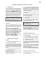
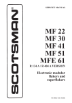
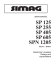
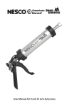
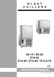
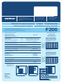
GB
Via del Lavoro, 9 C.P. 172
I - 31033 Castelfranco Veneto (TV)
ITALY EU
Tel. +39 0423 738452
Fax +39 0423 722811
[email protected]
www.castelmac.it
Fabbricatori di ghiaccio granulare Ice flakers Flockeneisbereiter
Machines à glace en grains Fabricadores de hielo in escamas
F200
I MODELLI E LE SPECIFICHE POSSONO ESSERE CAMBIATI IN QUALUNQUE MOMENTO SENZA PREAVVISO
MODELS AND SPECIFICATIONS ARE SUBJECT TO BE CHANGED WITHOUT NOTICE
WIR BEHALTEN DAS RECHT VOR JEDERZEIT ANDERUNGEN DER MODELLE UND DER TECHNISCHEN ANGABEN VORZUNEHMEN
LES MODELES ET CARACTERISTIQUES DES APPAREILS PEUVENT ETRE CHANGES SANS PREAVIS
LOS MODELOS Y LAS ESPECIFICACIONES PODRAN MODIFICARSE EN CUALQUIER SIN PREVIO AVISO
Produzione di ghiaccio in 24 ore fino a
Ice produced for 24 hours up to
Eisproduktion in 24 Stunden bis zu
Production de glace en 24 h jusqu’à
Produccion de hielo en las 24 horas hasta
kg. 200
aria
air
Luft
air
aire
RAFFR. AD ACQUA / WATER
COOLED / WASSERGEKÜHLT
REFR. A EAU / REFR. A AGUA
o acqua: consumo n. 50 litri per ora*
or water: consumption n. 50 litres per hour*
oder Wasser: Verbrauch n. 50 liter pro Stunde*
ou eau: consommation n. 50 litres par heure*
o agua: consumo n. 50 litros para hora*
Potenza assorbita / Absorbed power / Leistungsaufnahme
Puissance absorbée / Potencia Absorbida
W 760
Refrigerante / Refrigerant / Kältemittel / Réfrigérant / Refrigerant
R 404a
Attacco entrata acqua / Water iniet connection / Anschluss für Wasserzufluss
Prise entrée d’eau / Conexión entrada agua
Attacco scarico acqua / Water output connection / Anschluss für Wasserabfluss
Prise écoulement d’eau / Conexión desague
Alimentazione monofase/Single phase input/
Einphasige Spannung/Alimentation monophase
Alimentación monofásica
Temperatura acqua/Water temperature
Wassertemperatur/Température eau
Temperatura agua
Temperatura ambiente
Ambient temperature
Raumtemperatur
Température ambiante
Températura ambiente
Raffreddamento unità condensatrice
Condensing unit cooling
Kondensatoreinheit
Refroidissement de l’unité de condensation
Refrigeración de la unidad condensadora
3/4” Gas
mm. Ø 20
Deposito da abbinare / Bin to be used
D101 - D201
Carrozzeria / External structure
Ausfühnrung / Carrosserie / Carroceria
inox
Peso netto / Net weight / Netto Gewcht
Poids net / Peso neto
Kg. 49
32°
172
169
161
155
21°
186
183
175
169
15°
193
190
182
175
10°
200
197
189
183
kg
kg
kg
kg
RAFFREDDAMENTO AD ARIA
AIR COOLED - LUFTGEKÜHLT
REFR. A AIR - REFR. A AIRE
Temperatura acqua/Water temperature
Wassertemperatur/Température eau
Temperatura agua
Temperatura ambiente
Ambient temperature
Raumtemperatur
Température ambiante
Températura ambiente
a richiesta
on request
Lieferbar auf Wunsch
sur demande
según pedido
°C
10°
21°
32°
38°
Prod. ghiaccio in 24 h/Ice prod. per 24 h
Eisprod. in 24 h/Prod. de glace en 24 h
Prod. de hielo en 24 h
220V-240V - 50 Hz
Alimentazione voltaggi speciali:
Extra voltages:
Andere Spannungen:
Alimentation voltages spéciaux:
Otros voltajes especiales:
°C
10°
21°
32°
38°
32°
172
194
141
125
21°
186
178
155
139
15°
193
185
162
146
10°
200
192
169
153
kg
kg
kg
kg
Prod. ghiaccio in 24 h/Ice prod. per 24 h
Eisprod. in 24 h/Prod. de glace en 24 h
Prod. de hielo en 24 h
con temperatura acqua 15 °C
with water temperature 15 °C
mit Wassertemperatur 15 °C
avec température eau 15 °C
con temperatura agua 15 °C
560
533
WATER OUTLET
SCARICO ACQUA
WATER OUTLET - WATER COOLED ONLY
SCARICO ACQUA - SOLO PER RAFFREDDAMENTO AD ACQUA
WATER INLET - WATER COOLED ONLY
ENTRATA ACQUA - SOLO PER RAFFREDDAMENTO AD ACQUA
WATER INLET
ENTRATA ACQUA
CORD SET
CAVO DI ALIMENTAZIONE
F200 01/2008
45
188
83
354
Dimensioni
Dimensions
Masse
Dimensions
Dimensiones
296
525
(*)
PRODUZIONE DI GHIACCIO
ICE PRODUCTION
EIS PRODUKTION
PRODUCTION DE GLACE
PRODUCICON DE HIELO
GB
GENERAL INFORMATION AND INSTALLATION
A.
INTRODUCTION
This manual provides the specifications and
the step-by-step procedures for the installation,
start- up and operation, maintenance and
cleaning for the ICEMATIC F80C-F125CF120-F200-SF300-SF500-SFN1000 Modular
Icemakers. The Electronic Flakers and Superflakers are quality designed, engineered and
manufactured. Their ice making systems are
thoroughly tested providing the utmost in
flexibility to fit the needs of a particular user.
NOTE. To retain the safety and performance
built into this icemaker, it is important that
installation and maintenance be conducted
in the manner outlined in this manual.
Storage Bin
Since the F series Modular Flakers do not have
their own attached ice storage bins, it is necessary to use an auxiliary bin as detailed herebelow:
D101 in combination with F120-F200
D201 with its companion NKF201 Top Cover in
combination with F120 - F200 - SF300 - SF500
D310 with its companion NKF310 Top Cover in
combination with F120 - F200 - SF300 - SF500
B50 in combination with SF300 - SF500
D500 with its companion NKF500 Top Cover in
combination with SF300 - SF500
D700 with its companion NKF700 Top Cover in
combination with SF500 - SFN1000
4. On models F120, F200, SF300 and SF500
remove the top and front panel while on model
SFN1000 remove top and sides panels of the unit
and inspect for any concealed damage. Notify
carrier of your claim for the concealed damage
as stated in step 2 above.
5. Remove all internal support packing and
masking tape.
6. Check that refrigerant lines do not rub
against or touch other lines or surfaces, and that
the fan blades move freely.
7. Check that the compressor fits snugly onto
all its mounting pads.
8. See data plate on the rear side of the unit
and check that local main voltage corresponds
with the voltage specified on it.
CAUTION. Incorrect voltage supplied to
the icemaker will void your parts
replacement program.
9. Remove the manufacturer’s registration
card from the inside of the User Manual and fillin all parts including: Model and Serial Number
taken from the data plate.
Forward the completed self-addressed registration card to ICEMATIC/SCOTSMAN factory.
Storage bin (D101 - D201 - D310)
1. Follow the steps 1, 2 and
unpack the storage bin.
3 above to
2. Unloose the two bolts and remove the protection plate from the drain fitting on model D310.
B.
UNPACKING AND INSPECTION
3. Carefully lay it down on its rear side and fit
the four legs into their sockets.
Icemaker
1. Call your authorized ICEMATIC Distributor
or Dealer for proper installation.
2. Visually inspect the exterior of the packing
and skid. Any severe damage noted should be
reported to the delivering carrier and a concealed
damage claim form filled in subjet to inspection of
the contents with the carrier’s representative
present.
3. a) Cut and remove the plastic strip securing
the carton box to the skid.
b) Cut open the top of the carton and remove the
polystyre protection sheet.
c) Pull out the polystyre posts from the corners
and then remove the carton.
4. Remove all internal support packing and
masking tape as well as the plastic ice cube
deflector which is not used with the SCOTSMAN
Modular Flakers.
5. Remove the manufacturer’s registration
card from the inside of the User Manual and fillin all parts including: Model and Serial Number
taken from the data plate.
Forward the completed self-addressed registration card to ICEMATIC/SCOTSMAN factory.
Storage bin (B 1025 S - B 1350 S)
1. Follow the steps 1, 2 and
unpack the storage bin.
3 above to
11
GB
2. Lay carefully down the bin on its back to
protect the finish and remove the bolts holding
the shipping skid to the bin.
3. Screw-in the legs into the corresponding
tapped holes in the bin bottom and tighten to seat
the legs well against the bin bottom.
4. Connect the water drain line to the 1" female
drain fitting located in the bottom of the bin.
CAUTIONS. Avoid excessive tightening
force when connecting to this fitting.
Do not apply excessive heat if any
sweating of the fittings is necessary. Heat
conduction through the metal may melt
the threads in the plastic drain.
5. On model D700
only insert the longer
side of each plastic inspection window in the
upper track of the corresponding opening and
push it to force the window to enter into its seat.
3. On D201 and D310 Storage Bin inspect
its top mounting gasket which should be flat with
no wrinkles, to provide a good sealing when the
Top Cover is installed on top of it.
4. Place the NKF201-NKF310 Top Cover on
top of Storage bin using care not to wrinkle or
tear the gasket.
5. On the D500 and D700 Storage Bin
unloose the screws securing the S.S. Top
Cover to the storage bin and remove it.
6. Lay out on the bin top the plan of the ice
machine as it will be located on the bin and cut an
opening in the bin top for the ice drop area; cover
the edges of the opening with vinyl tape.
7. Install the gasket-on the bin top-around ice
drop opening of the bin top; apply sealant along
the inside of the gasket.
8. Position and install the four aluminium front
to rear stiffeners (U shaped) paying attention to
the guideline shown on the drawing.
CUT GASKET HERE
STIFFENER
BIN WALL GAKET
C.
LOCATION AND LEVELLING
WARNING. This Modular Flaker and
Superflaker is designed for indoor
installation only. Extended periods of
operation at temperature exceeding the
following limitations will constitute
misuse under the terms of the ICEMATIC
Manufacturer’s Limited Warranty resulting
in LOSS of warranty coverage.
1. Position the storage bin in the selected
permanent location.
Criteria for selection of location include:
a) Minimum room temperature 10°C (50°F)
and maximum room temperature 40°C (100°F).
b) Water inlet temperatures: minimum 5°C
(40°F) and maximum 35°C (90°F).
c) Well ventilated location for air cooled
models (clean the air cooled condenser at
frequent intervals).
d) Service access: adequate space must
be left for all service connections through the rear
of the ice maker. A minimum clearance of 15 cm
(6") must be left at the sides of the unit for routing
cooling air drawn into and exhausted out of the
compartment to maintain proper condensing
operation of air cooled models.
2. Level the Storage Bin Assy in both the left
to right and front to rear directions by means of
the adjustable legs.
12
TOP SHELL
NOTE. Bin wall gasket must be cut to clear
the stiffener ends as shown on drawing.
Do not put any stiffeners crossing the ice
drop opening.
9. Install the bin top in its position onto the bin
top by:
- place the rear side of top against rear edge
of the bin
- lower the front of the top onto the stiffeners
- re-fit the screws previously removed as
per step 5
10. Install the Modular Flaker or Superflaker
onto the Top Cover of storage bin pay attention
to match the ice chute with the Bin Top opening.
Installation of lift door catch (D500)
On the Storage Bin D500 when the ice maker
is installed flush with the bin front it is required to
mount the lift door catch as detailed herebelow.
1. Open all the way the lift door in the upright
position then place the door catch on the front
face of the ice maker and tape it in place.
GB
2. Drill two 3 mm holes in correspondance of
the catch mounting holes.
advisable to consider the installation of an
appropriate water filter or conditioner.
3. Remove the tape and fasten the catch
using the two self-tapping screws supplied.
WATER SUPPLY - WATER COOLED MODELS
D.
ELECTRICAL CONNECTIONS
See data plate for current requirements to
determine wire size to be used for electrical
connections. All ICEMATIC icemakers require
a solid earth wire.
All ICEMATIC ice machines are supplied from
the factory completely pre-wired and require only
electrical power connections to the wire cord
provided at the rear of the unit.
Make sure that the ice machine is connected to
its own circuit and individually fused (see data
plate for fuse size).
The maximum allowable voltage variation should
not exceed -10% and +10% of the data plate
rating. Low voltage can cause faulty functioning
and may be responsible for serious damage to
the overload switch and motor windings.
NOTE. All external wiring should conform to
national, state and local standards and
regulations.
The water cooled versions of ICEMATIC Ice
Makers require two separate inlet water supplies,
one for the water making the flaker ice and the
other for the water cooled condenser.
Connect the 3/4" GAS male fitting of the water
inlet, using the flexible hose supplied to the cold
water supply line with regular plumbing fitting and
a shut-off valve installed in an accessible position
between the water supply line and the unit.
WATER DRAIN
The recommended drain tube is a plastic or
flexible hose with 18 mm (3/4") I.D. which runs to
an open trapped and vented drain. When the
drain is a long run, allow 3 cm pitch per meter
(1/4" pitch per foot).
Install a vertical open vent on drain line high point
at the unit drain connection to ensure good
draining.
The ideal drain receptacle is a trapped and vented
floor drain.
Check voltage on the line and the ice maker’s
data plate before connecting the unit.
WATER DRAIN - WATER COOLED MODELS
E.
Connect the 3/4" GAS male fitting of the condenser
water drain, utilizing a second flexible hose to the
open trapped and vented drain.
This additional drain line must not interconnect to
any other of the units drains.
WATER SUPPLY AND DRAIN
CONNECTIONS
GENERAL
When choosing the water supply for the ice flaker
consideration should be given to:
a) Length of run
b) Water clarity and purity
c) Adequate water supply pressure
Since water is the most important single ingredient
in producting ice you cannot emphasize too
much the three items listed above.
Low water pressure, below 1 bar may cause
malfunction of the ice maker unit.
Water containing excessive minerals will tend to
produce scale build-up on the interior parts of the
water system while too soft water (with too lo
contents of mineral salts), will produce a very
hard flaker ice.
NOTE. The water supply and the water drain
must be installed to conform with the local
code. In some case a licensed plumber and/
or a plumbing permit is required.
F.
1. Is the unit in a room where ambient
temperatures are within a minimum of 10°C (50°F)
even in winter months?
2. Is there at least a 15 cm (6") clearance
around the unit for proper air circulation?
3.
WATER SUPPLY
Connect the 3/4" GAS male of the water inlet
fitting, using the food grade flexible hose supplied
to the cold water supply line with regular plumbing
fitting and a shut-off valve installed in an
accessible position between the water supply
line and the unit.
If water contains a high level of impurities, it is
FINAL CHECK LIST
Is the unit level? (IMPORTANT)
4. Have all the electrical and plumbing
connections been made, and is the water supply
shut-off valve open?
5. Has the voltage been tested and checked
against the data plate rating?
6. Has the water supply pressure been checked
to ensure a water pressure of at least 1 bar (14
psi).
13
GB
7. Have the bolts holding the compressor down
been checked to ensure that the compressor is
snugly fitted onto the mounting pads?
Manual and been instructed on the importance of
periodic maintenance checks?
8. Check all refrigerant lines and conduit lines
to guard against vibrations and possible failure.
11. Has the Manufacturer’s registration card
been filled in properly? Check for correct model
and serial number against the serial plate and
mail the registration card to the factory.
9. Have the bin liner and cabinet been wiped
clean?
10. Has the owner/user been given the User
12. Has the owner been given the name and
the phone number of the authorized ICEMATIC
Service Agency serving him?
G. INSTALLATION PRACTICE
1.
2.
3.
4.
5.
6.
7.
8.
9.
10.
Hand shut-off valve
Water filter
Water supply line (flexible hose)
3/4" GAS male fitting
Power line
Main switch
Drain fitting
Vented drain
Vented drain
Open trapped vented drain
WARNING. This icemaker is not designed for outdoor installation and will not function in
ambient temperatures below 10°C (50°F) or above 40°C (100°F).
This icemaker will malfunction with water temperatures below 5°C (40°F) or above 35°C
(90°F).
14