1
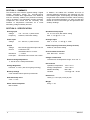
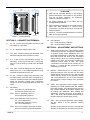
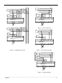
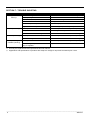
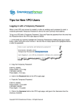
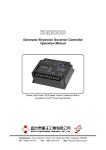
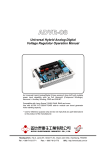
ADVR-16 Universal Hybrid Analog-Digital Voltage Regulator Operation Manual Self Excited 16 Amp Analog / Digital Voltage Regulator for use in 170 510 Vac brushless generators with paralleling compatibility Headquarters : No.3, Lane 201, Chien Fu St., Chyan Jenn Dist., Kaohsiung, TAIWAN Tel : + 886-7-8121771 Fax : + 886-7-8121775 URL : http://www.kutai.com.tw SECTION 1 : SUMMARY The ADVR-16 is an advance (Hybrid Analog / Digital Voltage Regulator) design for general-purpose isochronous stand alone applications. The ADVR-16 uses an extremely reliable CPU (Central Processing Unit) in its design. This eliminates complex analogue components and circuits that are inherently over sensitive to temperature anomalies, as a result eliminating voltage instability and drift. In addition, we added over excitation and loss of sensing shutdown protections, with matching U/F, O/E LED indicator lights. Consequently, this AVR prevents the generator from excitation overload, with its resulting exciter and regulator damage. It is easy to install and flexible for use in both shunt type and generators with auxiliary windings. SECTION 2 : SPECIFICATION Sensing Input Voltage 170 510 Vac, 1 phase 2 wire Frequency 50/60 Hz, DIP switch setting Quadrature Droop Input CT 1A / 5A > 5VA, DIP switch setting Max. +/- 7% @ P.F +/- 0.5 Power Input Voltage Analogue Input Max. +/- 5 Vdc +/- 10% @ +/- 3 Vdc Output Voltage Current 60 300 Vac, 1 phase 2 wires Under Frequency Protection (Factory Presets) Resistance Max. 90 Vdc @ power input 240 Vac Continuous 16A Intermittent 20A for 10 secs. ≧ 5 ohms Fuse Spec. Slow blow 6.35 x 32mm 16A / 500V External Voltage Adjustment +/- 5% 2K ohms 1 watt potentiometer Voltage Regulation Less than +/- 0.5% ( with 4% engine governing ) Build Up Voltage 5 Vac residual volts at power input terminal Soft Start Ramp Time 2 sec. +/- 10% Static Power Dissipation Max.10 watts 50/60 Hz, DIP switch setting Over Excitation Protection Max. DCV 95% 20 secs. Voltage Thermal Drift Less than 3% at temperature range -40 to +70 ˚C Environment Operation Temperature Storage Temperature Relative Humidity Vibration -40 to +70 ˚C -40 to +85 ˚C Max. 95% 3.3 Gs @ 100 2K Hz Dimensions 162.0 (L) x 112.0 (W) x 43.0 (H) mm Weight 535 g +/- 2% ___________________________________________________________________________________________ 2 ADVR-16 112.0 88.0 43.0 18.3 ATTENTION 1. AVR can be mounted directly on the engine, genset, switchgear, control panel, or any position that will not affect operation. For dimension reference, please see Figure 1. 162.0 138.0 ADVR-16 2. All voltage readings are to be taken with an average-reading voltmeter. 3. Secure all wiring connection. Do not install AVR at a place with high vibrations to prevent loose connections. For safety do not touch the heat sink while in operation. 5.2 Unit : mm Figure 1 4. Terminal:“Fast-On” terminals 6.35mm (1/4 inch) & With 4mm crimping terminal. Outline Drawing SECTION 3 : CONNECTION TERMINAL 3.1 P1, P2:Power Input Terminals from 60 to 300 Vac 50/60 Hz -16A rated. 3.2 F+, F-:Maximum Output current 16A. 3.3 VS1, VS2:Voltage sensing input terminals, Volts selected using DIP SW1 for 220V or 440V. 3.4 K, L:Load Current Compensation (Droop), CT secondary current input selected by using DIP SW 1A or 5A (If droop not used leave terminals open). 3.5 VR1, VR2:External Voltage trim use, 2K ohms 1 watt trimmer for +/- 5% voltage adjustment. Keep terminals shorted when not in use. 3.8 LED Indicator U/F:Under Frequency Indicator O/E:Over Excitation Indicator SECTION 4 : ADJUSTMENT AND SETTING 3.6 3.7 A1, A2:Analogue Voltage Input terminals used for Power Factor correction from a external PLCThe PLC controls provides a DC voltage signal to adjust the generator voltage. Max. Adjustment range is +/- 5 Vdc. Keep terminals open when not used. 4.1 TRIM works together with a bias voltage applied to terminals A1 and A2. This signal is supplies by an external Power Factor Paralleling PLC. Use the TRIM potentiometer to adjust the DC voltage input that controls the level of the generator’s output voltage. When set counter-clockwise the control level is zero, and if moved clockwise the maximum control range is 10%. The signal connected to A1 and A2 can be unipolar (0,+) or bipolar (+,). Check with the manufacture of the Paralleling control PLC. 4.2 DROOP:Select switch K or L pending on the secondary current of the CT that you are using. Voltage droop works when the CT and the AVR senses that the output of the generator voltage and current waveforms are out of synch and the AVR droops the output voltage of the generator to correct it. 4.3 STAB:If the generator output voltage oscillate, adjusting the STAB potentiometer will stabilize the output voltage, over adjustment will result in high voltage variation when load is applied. Use an analog type multimeter when making this adjustment. Connect the meter to terminals F+ and F- and slowly adjust STAB potentiometer to the point when the pointer stops moving. 4.4 VOLT:Move to set the generator output voltage. Set DIP Switch 1 to the generator working voltage. DIP Switch SW1:OFF 220 Vac (170 to 260 Vac) ON 440 Vac (340 to 510 Vac) SW2:OFF CT Secondary Input 1A ON CT Secondary Input 5A SW3:OFF Generator Frequency 60 Hz, 52 61 Hz Adjustment ON Generator Frequency 50 Hz, 42 51 Hz Adjustment SW4:OFF Over excitation protection enabled Set SW1 to OFF (220V) for use from 170 to 260 Vac ON Over excitation protection disabled Set SW1 to ON (440V) for use from 340 to 510 Vac ___________________________________________________________________________________________ ADVR-16 3 When using and external VR set it to the central position and adjust the AVR VOLT trim to the rated voltage. 5.2.2 “DANGER” When the AVR is working never touch or ground the heat sink on the AVR. The AVR heat sink is an electrically live terminal. A warning sticker is in place on top of the heat sink. NOTE If the external VR is not used, short terminal VR1 and VR2. 4.5 U/F:Under Frequency protection setting. At 50 Hz U/F factory set at 45 Hz At 60 Hz U/F factory set at 55 Hz To adjust the U/F setting, select the correct system frequency, start engine and adjust engine speed to the required U/F frequency (for example 55 Hz or 45 Hz), slow adjust U/F potentiometer until the U/F red LED turn ON, returning the engine speed to normal turn the LED off. Function of the Under Frequency trim pot: 4.5.1 During start up or shutdown, the engine speed changes going over or under its rated RPM (Hz). This AVR has an Under Frequency circuit to protect the AVR and exciter; you do not need to disconnect the AVR when idling the engine. 4.5.2 If load is higher than the generator’s capacity, the Under Frequency activates, reducing the generator’s voltage preventing generator overload. 4.6 Over Excitation Protection: 4.6.1 This AVR has over Excitation Protection preventing the generator from working under unusually high excitation. Excitation Protection includes generator overload, accident removal of sensing wires, and incorrect voltage setting. When problems occur, the AVR will gradually shutdown the excitation voltage to the minimum residual voltage. If the O/E LED turn ON and stays ON, you need to reset the AVR by shutting the engine for 10 seconds. When working the generator in parallel this protection is not required, the user can disable this function by switching DIP switch SW4 to ON position, vice versa. SECTION 5 : NOTICE OF USE 5.1 Installation Notice:(Refer to Figure 2 and 4). 5.1.1 Only, a trained professional can Installation, calibrate and inspections this AVR. 5.1.2 Install this AVR inside the generator enclosure away from moisture, corrosion and from any easy to reach area. 5.2 Generator Operation Notice: 5.2.1 During operation, the temperature on the surface of the AVR can reach higher the 60 ˚C / 140 ˚F. SECTION 6 : FIELD FLASHING When the regulator is installed correctly but the generator is failed to generate power. Besides carbon brushes were worn out, here are two possible causes below. 6.1 The polarity of field is inverse Solution:Exchange the connection of F+ and F-. 6.2 The residual voltage is less than 5 Vac, Solution 1: 6.2.1 Shut down generator, disconnect the wiring between AVR and generator then flash the field. Flashing duration = 3 seconds. (See wiring in Figure 2) Resistor 3 – 5 ohms for full wave AVR Resistor 5 – 10 ohms for half wave AVR Warning!! Over field flashing may damage the field winding of generator. 6.2.2 Restart generator and measure the residual voltage by AC Voltmeter, if it is still less than 5 Vac, repeat the previous process, after several times, the residual voltage still cannot be built, Kutai EB500 is strongly recommended, see Figure 2. R G ~ S T Field FR SW - V ~ Figure 2 F+ + BATT. Manual Field Flash WARNING Overly field flashing may damage the AVR or generator excitation winding. Please make sure you have read and understand the contents of the instruction manual prior to installation. Incorrect wiring connection may result in irreversible damage to the product and other equipments. ___________________________________________________________________________________________ 4 ADVR-16 R R S GEN S T GEN T N N Field Field P2 P1 F+ F- L K VS2 P2 P1 F+ F- VS1 L K VS2 VS1 A1 A2 ADVR16 ADVR16 VR1 VR2 A1 VR1 VR2 A2 EXT. VR EXT. VR R Figure 4 S 220V Connection GEN T R N S GEN T Field N P2 P1 F+ F- L K VS2 VS1 A1 A2 Field ADVR16 ADVR-16 VR1 VR2 P2 P1 F+ F- L K VS2 VS1 A1 A2 ADVR16 VR1 VR2 EXT. VR EXT. VR Figure 3 Paralleling Connection Figure 5 380 / 480V Connection Field R S GEN T N Aux. Winding 60~300v P2 P1 F+ F- L K VS2 VS1 A1 A2 ADVR16 VR1 VR2 EXT. VR Figure 6 Auxiliary Winding ___________________________________________________________________________________________ ADVR-16 5 SECTION 7 : TROUBLE SHOOTING SYMPTOM Voltage does not build up Low output voltage Over output voltage Output voltage unstable (Hunting) POSSIBLE CAUSES Residual voltage below 5 Vac SOLUTIONS Reference from section 6. Field Flashing F+, F- polarity reversed F+ and F- reverse the connection F+, F-, P1, P2, VS1, VS2 not connected Reference from Figure 4 and 5 connection Burnt fuse Change fuse 16A 500V Ext. Switch (Breaker) not turned on Switch on (ON) Engine RPM under speed Increase engine speed / frequency above 25 Hz Poor adjustment is made Read start procedure carefully and adjust again U/F protection activated Increase generator speed U/F activated / Incorrect voltage selection Read user’s manual to select correct voltage Poor adjustment is made Read start procedure carefully and adjust again Incorrect voltage selection Read user’s manual to select correct voltage Poor adjustment is made Read start procedure carefully and adjust again Field voltage requirement lower the rang of regulator Inquire our distributor to solve ※ Use only the replacement fuses specified in this user manual. ※ Appearance and specifications of products are subject to change for improvement without prior notice. ___________________________________________________________________________________________ 6 ADVR-16