1
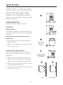
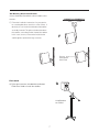
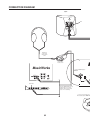
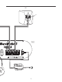
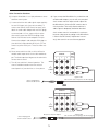
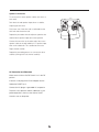
User Manual
3
TABLE OF CONTENTS
Introduction ................................................................4
INTRODUCTION
Carton Contents..........................................................5
Thanks for choosing the MicroWorks II Multimedia
Setup Options..........................................................6-7
Speaker System. It features the finest drivers, precision
Connection Diagram ..............................................8-9
internal crossover and amplifier circuitry and an ele-
Positioning Your Speakers ..................................10-11
gant enclosure design.
Connections ........................................................12-15
Operation and Final Adjustment ..............................16
The main left and right speakers feature magnetic
Specifications ..........................................................17
shielding, allowing placement near any sensitive electronic devices.
The Product Development Team at Cambridge
SoundWorks believes there is no better combination of
audiophile-level attention to detail and reasonable cost.
Inspecting For Damage
Examine the speaker system carefully for shipping
damage. If there is any, do not install or use the system. Return the speaker to the store where you made
the purchase or call Cambridge SoundWorks at:
1-800 FOR-HIFI (1-800-367-4434) for assistance.
After Unpacking
Store the shipping carton and packing material for
future transport needs.
QUICK SETUP
If you have connected amplified subwoofer/satellite
systems before, the Connection Diagram on pages 8-9
may be all you need to get set up and operating.
4
CARTON CONTENTS
A) Two Satellite Loudspeakers
B) Desktop Stands,Thumb screws (installed on satellites)
B
A
C) Wallmount hardware, Self-adhesive Feet
D) Hook and Loop fastener (for volume control, if not
used on Desktop Stand)
E) One Subwoofer/Amplifier Loudspeaker
F) Power Adapter (AC to AC)
G) Volume On/Off Control
H) 2 Satellite Connection Cables (2-meters)
C
No.10 screws and
plastic anchors
Rubber Feet
D
E
F
Green to signal source
G
Blue to subwoofer
H
5
SETUP OPTIONS
Cambridge SoundWorks, Inc. supplies screws and plastic
anchors for convenience, but it is the speaker purchaser’s
responsibility to insure that any speaker mounting or
placement is secure, stable and reliable. Cambridge
SoundWorks assumes no responsibility for damage to its
products or any damage to property resulting from speaker
A
positioning or placement.
SUBWOOFER/AMPLIFIER
The Subwoofer/Amplifier requires no assembly.
SATELLITES
Desktop Placement
Each satellite is shipped with a Desktop Stand installed.
You can also mount the Volume Control to a Desktop Stand
(see page 12).
Shelf Placement (or other flat surface) without the
Desktop Stand
B
A) Desktop Stand Removal: unscrew the thumbscrew to
release the satellite.
B) Apply the soft, self-adhesive feet to the bottom surface
Apply Feet to
Bottom for Flat
Surfaces
of each satellite, as shown.
Wall Mounting With Supplied Hardware
C
Note: Use the “hook and loop” fastener to secure the
volume control to a convenient flat surface if not using the
Apply Feet to Back
for Wall Mounting on
Screwhead
Desktop Stand
C) Apply the soft, self-adhesive feet to the back of the
satellite as shown. The feet provide mounting stability
and protect the finish of both the wall and the satellite.
D) Install the No.10 screw and anchor in the wall so that its
D
E
screwhead protrudes about 3/8 inch.
E) Adjust the screw so each satellite can be hung with just
a small amount of pressure.
Install
6
Mount Speaker
Wall Mounting With A Swivel Bracket
Contact Cambridge SoundWorks about available swivel
brackets.
F) Follow the installation instructions for your particular mounting bracket to attach it to a flat surface. If
desired, you can install the whole bracket/satellite
assembly inverted. This places the bracket above
the satellite, concealing it when viewed from below.
In this case, remove, invert and re-install the the
F
satellite grille to position the logo correctly.
Remove, Invert
and Replace
Grille Panel
Floor Stands
G
G) Follow the instructions included with the Newton
ST300 Floor Stands to install the satellites.
Using Speakers
on a Stand
7
CONNECTION DIAGRAM
Right
Speaker
RED
Headphones
connect to the
Volume On/Off
control
MicroWorks II
Volume Control
MusicWorks
Connect the blue miniplug to
INPUT A.
AUDIO OUT
Computer sound card
Insert the green miniplug into your
primary music source’s stereo
minijack output (a sound card, a
stereo TV or a Cambridge
Connect a second sound source
with a variable output to INPUT B.
Portable
Playe
8
Left
Speaker
RED
MicroWorks II
Subwoofer
Input Panel
RED
RED
R
-
R +
-
L
+
Music
er
9
POSITIONING YOUR SPEAKERS
SUBWOOFER/AMPLIFIER
Place the Subwoofer cabinet on the floor, preferably
near a wall. Do not place it on a desktop or shelf.
For the most efficient bass performance, place the
subwoofer near a corner. If the subwoofer is placed
away from the intersection of two room surfaces, the
maximum bass output will be reduced.
Use the Bass Level control to adjust the bass output to
your desired balance. Recommended Bass control
settings for each type of location are shown.
Maximum Bass Output
Moderate Bass Output
Least Bass Output
Suggested
Bass Control
Compensation
SATELLITES
Desktop Placement
The Desktop Stands improve the sound for both
a standing or seated listener.
MusicWorks
Position the satellites so they form a 45 degree
angle from your listening position.
45 ˚
10
le
ang
le
ang
45 ˚
POSITIONING THE SATELLITES
Wall Placement
(Swivel brackets available separately)
Avoid facing a satellite parallel to a nearby wall (within
6-8 inches). The reflected sound from the wall
A
degrades the sound coming directly from the satellite
(diagram A).
Try to position wall-mounted satellites so both are
approximately at your ear level while sitting or slightly
OK
higher. Make sure the speakers form at least a 20degree angle with your listening position. An angle
greater than 55 degrees sounds like two separate
speakers, rather than forming a continuous image of
sound between the two speakers (diagram B).
Too
Close
When using the speaker for video sound, place the
Too
Close
satellites relatively close to the left and right side of the
television monitor, forming no more than a 45 degree
angle with your listening position (diagram C).
B
MAXIMUM RECOMMENDED DISTANCE
APART FOR HOME THEATER
RECOMMENDED DISTANCE
APART FOR STEREO
20 - 55
ANGLE
C
EAR LEVEL
OR
SLIGHTLY
HIGHER
LEVEL
WITH
CENTER
SPEAKER
45 ANGLE
POWERED
SUBWOOFER
Shelf Placement
Place the satellites as close to the edge of the shelf as
D
possible for best sound (diagram D). If the shelf is at
ear level or above, it is not necessary to use the
Desktop Stand
Flush with edge if possible
11
CONNECTIONS
Volume On/Off Control
A) If you are using the Desktop Stand, slide the
Volume Control onto the support strut on one
of the stands.
A
B) The BLUE miniplug of the Volume On/Off Control
should be inserted into the subwoofer minijack “A”
labeled “TO VOLUME CONTROL.”
Signal Connections
C) The GREEN miniplug of the Volume On/Off Control
should be connected to your primary audio program source.
INPUT B is a second audio input that blends with
INPUT A. Connect a second audio program source
here. For a source with a 3.5 mm minijack output (like
a headphone jack or line out jack on a portable CD
C
player), use a 2-meter signal cable with a 3.5 mm
MusicWorks
miniplug at each end. Other sources may need a
cable with a 3.5 mm miniplug and two RCA plugs or a
3.5 mm stereo miniplug and 3.5 mm stereo minijack.
Headphones
Insert the green miniplug into
your primary music source’s
stereo minijack output (a sound
card, a stereo TV or a
Cambridge SoundWorks
MusicWorks)
AUDIO OUT
Plug headphones with a 3.5 mm stereo miniplug into
the headphone jack of the Volume On/Off control.
Computer sound card
Using headphones mutes the main speakers and
subwoofer.
The headphone jack on the Volume On/Off Control is
a direct connection to the signal Source. Headphone
output must be controlled at the signal source. The
speaker volume control does not affect the
Connect the blue
miniplug to INPUT A.
headphone jack.
B
R
-
12
R +
-
L
+
Other Connection Situations
d) If you connect the MicroWorks II to a television with
1) Using the MicroWorks II as a high performance stereo
variable audio outputs, you can still use your televi-
television sound system.
sion's remote control to adjust overall output. Set
a) A stereo television with audio signal output typically
the MicroWorks II Volume On/Off control at the 12
has two RCA-type jacks (one red, one white). To
o'clock position. Then verify that the television's
connect the Volume On/Off Control to these jacks,
audio output is adequately loud when the televi-
obtain an audio cable adapter with two RCA plugs
sion's remote control is increased to it's maximum.
at one end and a 3.5 mm stereo minijack at the
Increase or decrease the setting on the MicroWorks
other end. Connect the GREEN miniplug of the
II Volume On/Off Control (if adjustment is neces-
Volume On/Off Control to the adapter's minijack.
sary), then stow it in an out of the way position.
Connect the adapter's red and white RCA plugs to
your television’s red and white RCA jacks. (Do not
connect to yellow RCA jacks. These are video outputs.)
b) Some stereo televisions offer a choice of fixed or
VIDEO IN
variable audio output level. Choose the variable output. The fixed output level bypasses the television’s
2
1
AUDIO
OUT
3
(VARIABLE)
remote volume control.
c) Turn off your television’s internal speakers. This
VIDEO
control could be located on the front or back
control panels of your television, or it may be an
L
(MONO)
AUDIO
R
Signal Cable
One 3.5 mm stereo minijack to two RCA plugs
Green miniplug from
Volume On/Off control
OR
VIDEO IN
1
2
AUDIO
OUT
3
(VARIABLE)
VIDEO
L
(MONO)
AUDIO
R
Minijack to minijack adapter
Green miniplug from
Volume On/Off control
13
Signal Cable
One 3.5 mm stereo miniplug to two RCA plugs
2) Using the MicroWorks II as a sound system for a
component CD player.
COMPONENT CD OUTPUT
Typically, there are two RCA-type jacks (one red,
one white) on the CD player. To connect to these
jacks, obtain a stereo signal cable with two RCA
OUT
plugs on one end and a 3.5 mm stereo minijack at
RIGHT LEFT
the other end. Connect the RCA plugs to the RCA
jacks on the player. Connect the Volume On/Off
Control green miniplug to the minijack of the
adapter.
Signal Cable
One 3.5 mm stereo miniplug to two RCA plugs
Green miniplug from
Volume On/Off control
Minijack to minijack adapter
OR
OUT
RIGHT LEFT
Signal Cable
One 3.5 mm stereo minijack to two RCA plugs
Green miniplug from
Volume On/Off control
14
Speaker Connections
To connect the 2-meter speaker cables (two wires at
each end):
Push back the red speaker input tab on a satellite,
exposing the wire hole.
Fully insert one of the wires with a red band into the
wire hole and release the tab.
Repeat the procedure with the adjacent speaker wire
and the black speaker input tab on that speaker.
Connect the two wires at the other end of that same
speaker cable to the red and black “R” speaker input
tabs on the subwoofer. This satellite becomes the
Right channel satellite.
Repeat the preceding process to connect the other
satellite (making it the Left channel satellite).
AC Connection and Placement
Make sure the Volume On/Off Control is in in the Off
position.
Insert the small plug of the Power Adapter into the
Subwoofer POWER jack.
Connect the AC plug to a grounded AC receptacle.
Place the main speakers and the subwoofer in your
preferred positions, then use the Volume On/Off
Control to turn on the power.
15
OPERATION AND FINAL ADJUSTMENT
1) Use the Volume Control or the signal source control
to vary output level.
2) Defeat or cancel any “tone control” or other sound
adjustments within your audio program source.
Portable CD players may have “bass boost” switches and many computer sound programs have
audio adjustments concealed in drop-down menus.
3) If possible, play a variety of musical CDs with good
deep bass content to judge the best setting of the
SUBWOOFER LEVEL control.
Cleaning
The painted surfaces of the satellites and subwoofers
should be wiped with a cloth or brushed clean. The
grille panel material can be vacuumed or brushed
clean.
16
SPECIFICATIONS
Analog Input:
775 millivolts for full output
10 kohms input impedance
Amplifiers:
Satellite: 20 watts continuous at 1 kHz, two channels
driven at less than .1% total harmonic distortion.
Subwoofer: 40 watts continuous at 100 Hz, one channel
driven at less than .3% total harmonic distortion.
System Frequency response:
Satellite: 150 Hz to 15 kHz, +/- 3 dB
Subwoofer: 45 Hz to 150 Hz +/- 3 dB
Drivers:
Nominal 6.5 inch subwoofer driver with 8 inch passive radiator
Nominal 3.5 inch satellite driver
AC Voltage:
120VAC, 60Hz
Dimensions (H x W x D) and Weights
Satellite (without stand)
4 1/2" x 4 3/8" x 4 7/8"
113mm x 108mm x 125mm
2 pounds, 1 ounce
916 grams
Satellite (with stand)
6 1/4" x 4 3/8" x 5 5/8"
160mm x 108mm x 143mm
2 pound, 3 ounces
988 grams
Subwoofer
11 1/8" x 10" x 10 3/4", including cables
263mm x 255mm x 275mm
12 pounds, 12 ounces
5.5 kg
17
CAMBRIDGE SOUNDWORKS, INC.
26 DARTMOUTH STREET, WESTWOOD, MA 02090
Telephone: 1-800-367-4434
Fax: 1-617-527-3194
A
Company
P81-1750